Dynamic Coordinated Shifting Control of Automated Mechanical Transmissions without a Clutch in a Plug-In Hybrid Electric Vehicle

Abstract
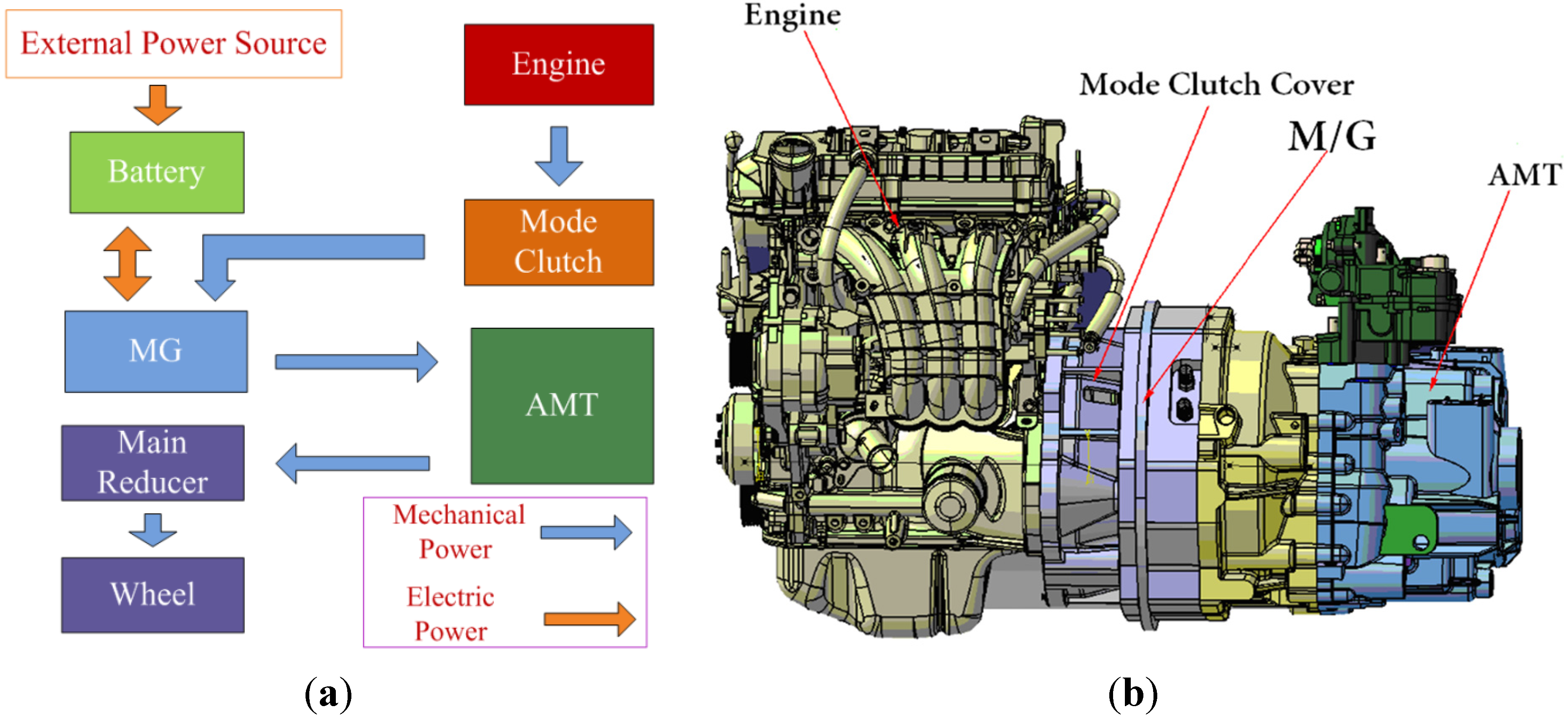
:1. Introduction
2. AMT Shifting without Clutch and Evaluation Parameters

3. Dynamic Analysis of AMT Shifting without a Clutch
3.1. Dynamic Model for AMT Shifting
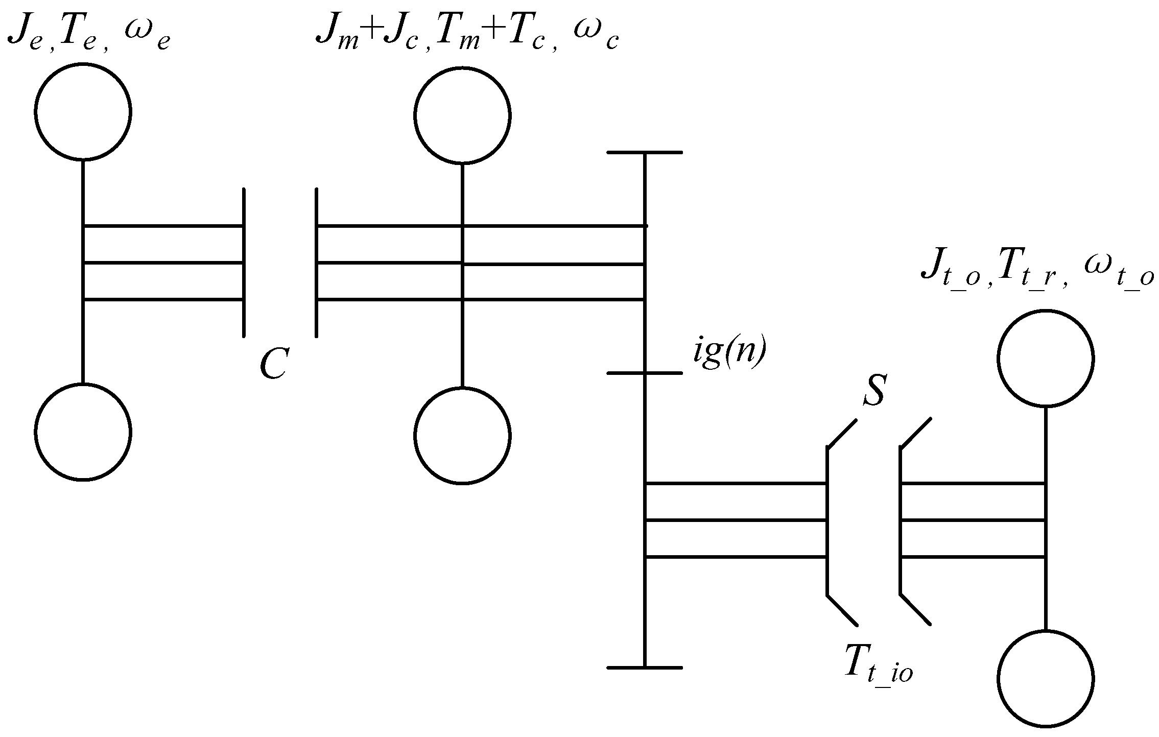
3.2. Dynamic Analysis of AMT Shifting without Clutch
3.2.1. Dynamic Analysis of Pre-Shifting
3.2.2. Dynamic Analysis after Shifting off
3.2.3. Dynamic Analysis of Synchronization
3.2.4. Shift on
3.2.5. Restoring the Engine and Motor Torque
4. Coordinated Torque Control of the Engine and Motor

5. Dynamic Coordinated Control Strategy for AMT Shifting without a Clutch
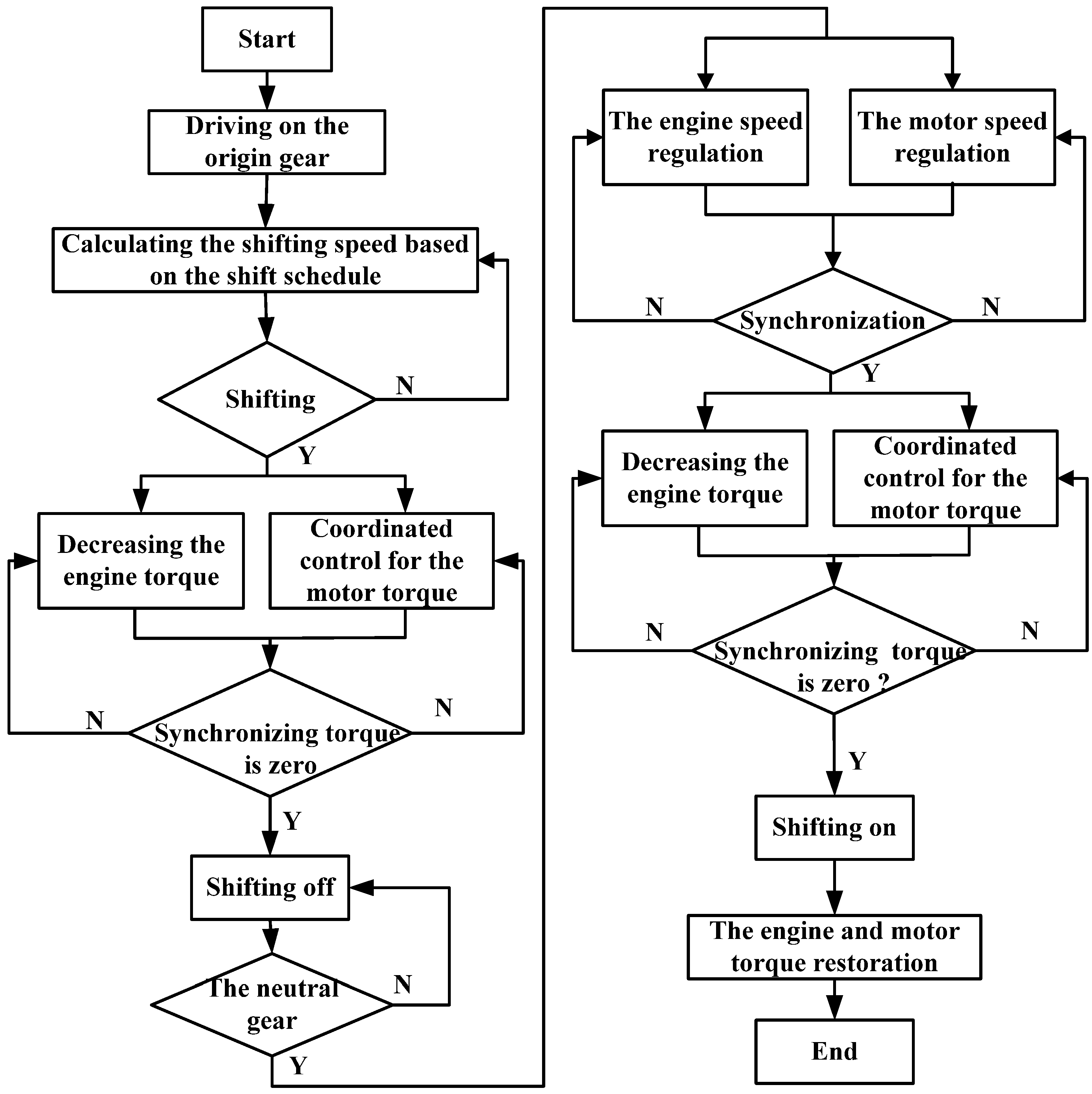
5.1. Shifting Control Flow
5.2. Control Strategy for AMT Shifting without Clutch
5.2.1. The Coordinated Control of the Engine and Motor Torque before Shifting off
- (1)
- The throttle opening is controlled to reach the threshold value αmin in which the engine operates well.
- (2)
- The operating mode of the electric machine switches from the motor to the generator when the throttle opening reaches the threshold value αmin.
- (3)
- As the throttle opening is kept constant, the engine output torque can be obtained from the curve of steady output torque and speed acquired from the engine controller.
- (4)
- Based on the above engine output torque, the total output torque of the engine and the motor is controlled to be zero by controlling the motor output torque.
- (5)
- The shifting off action can be performed soon after the total output torque of the engine and the motor becomes zero.

5.2.2. The Speed Synchronization Control
5.2.3. The Coordinated Control of the Engine and Motor Torque before Shifting on
- (1)
- After the speed synchronization, the operating mode of the electric machine switches from the motor to the generator.
- (2)
- The throttle opening is kept on the threshold value αmin, the engine output torque can be obtained from the curve of steady output torque and speed acquired from the engine controller.
- (3)
- Based on the above engine output torque, the total output torque of the engine and the motor is controlled to be zero by controlling the motor output torque.
- (4)
- The shifting on action can be performed soon after the total output torque of the engine and the motor becomes zero.
5.2.4. The Engine and Motor Torque Restoration after Shifting
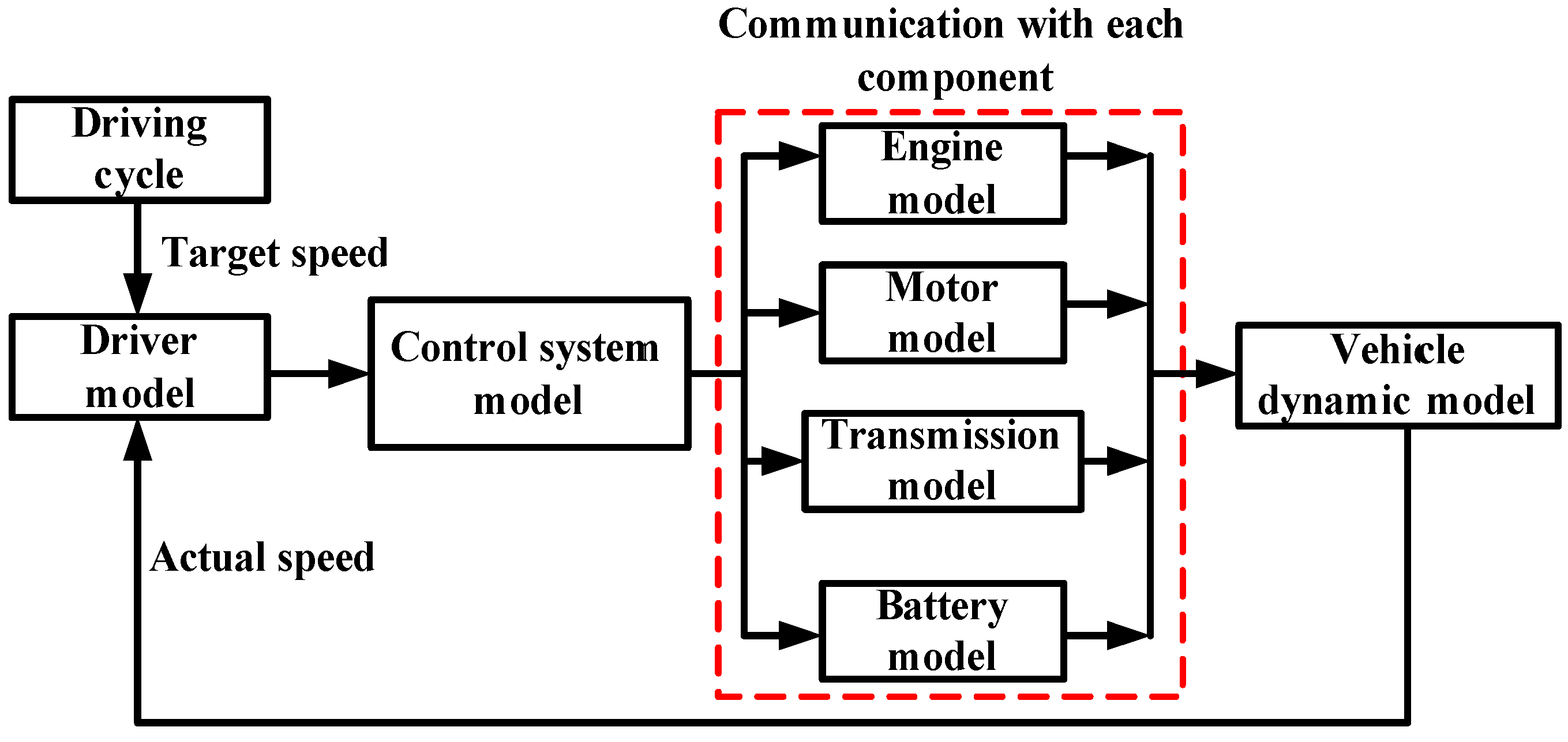
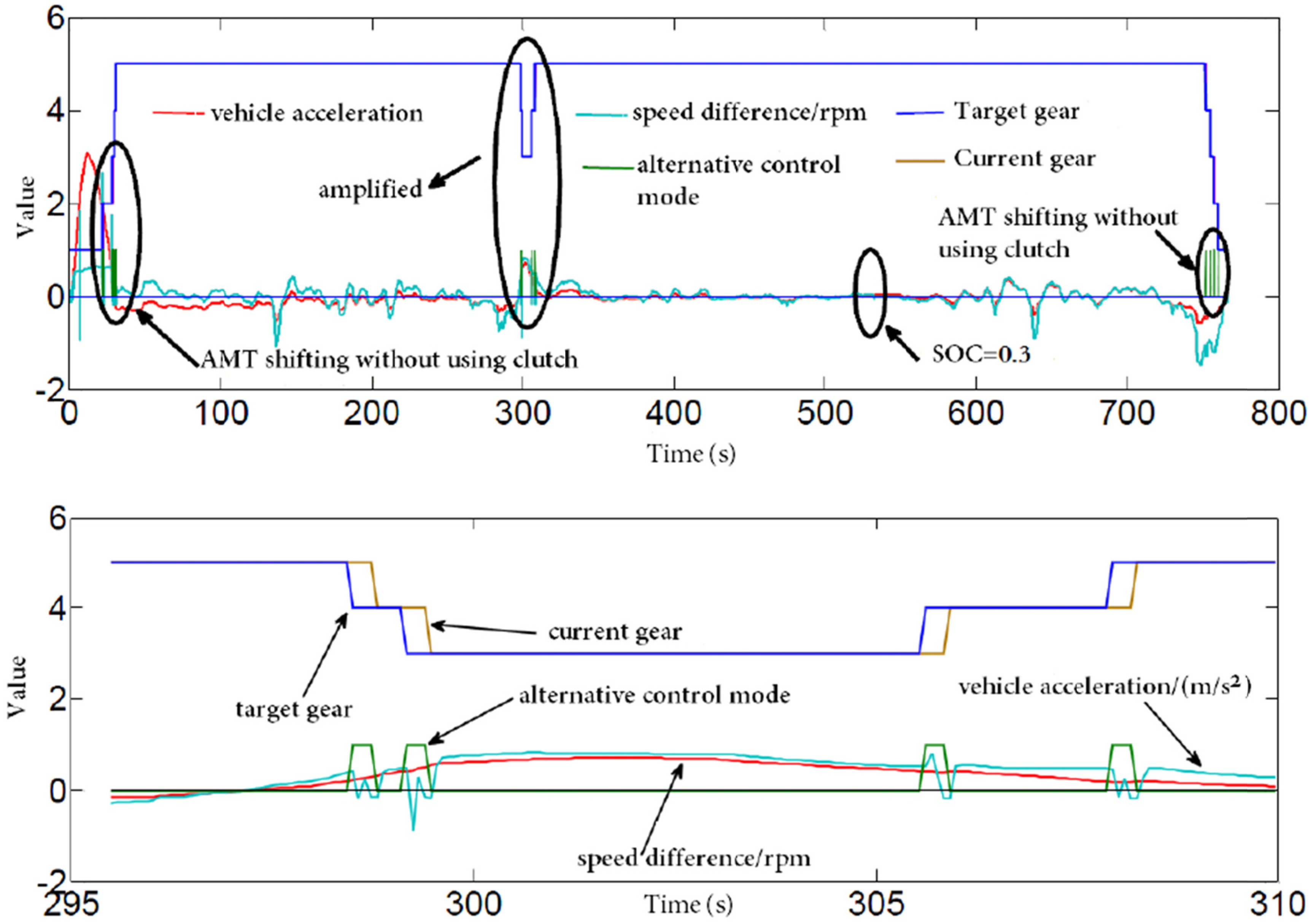
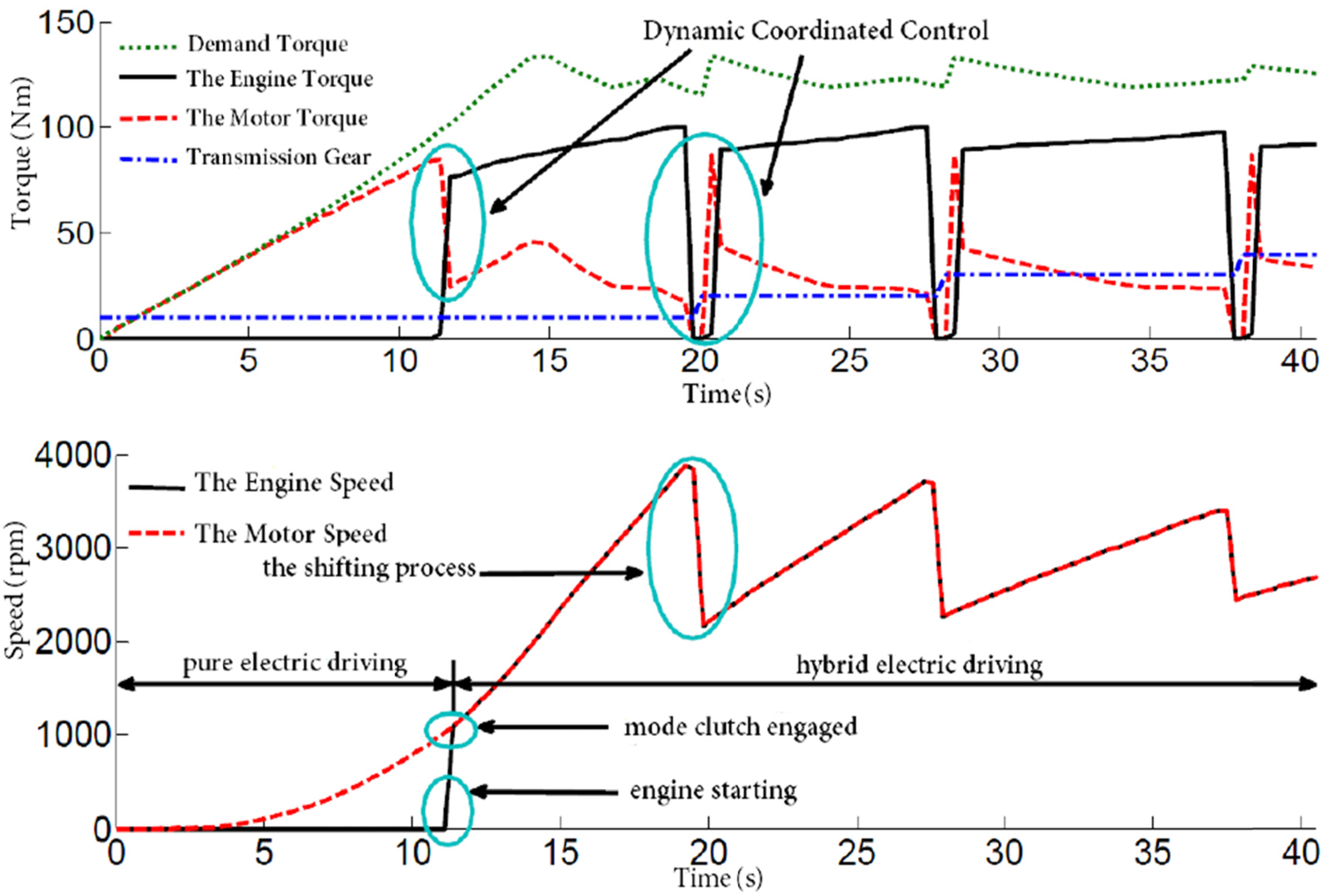
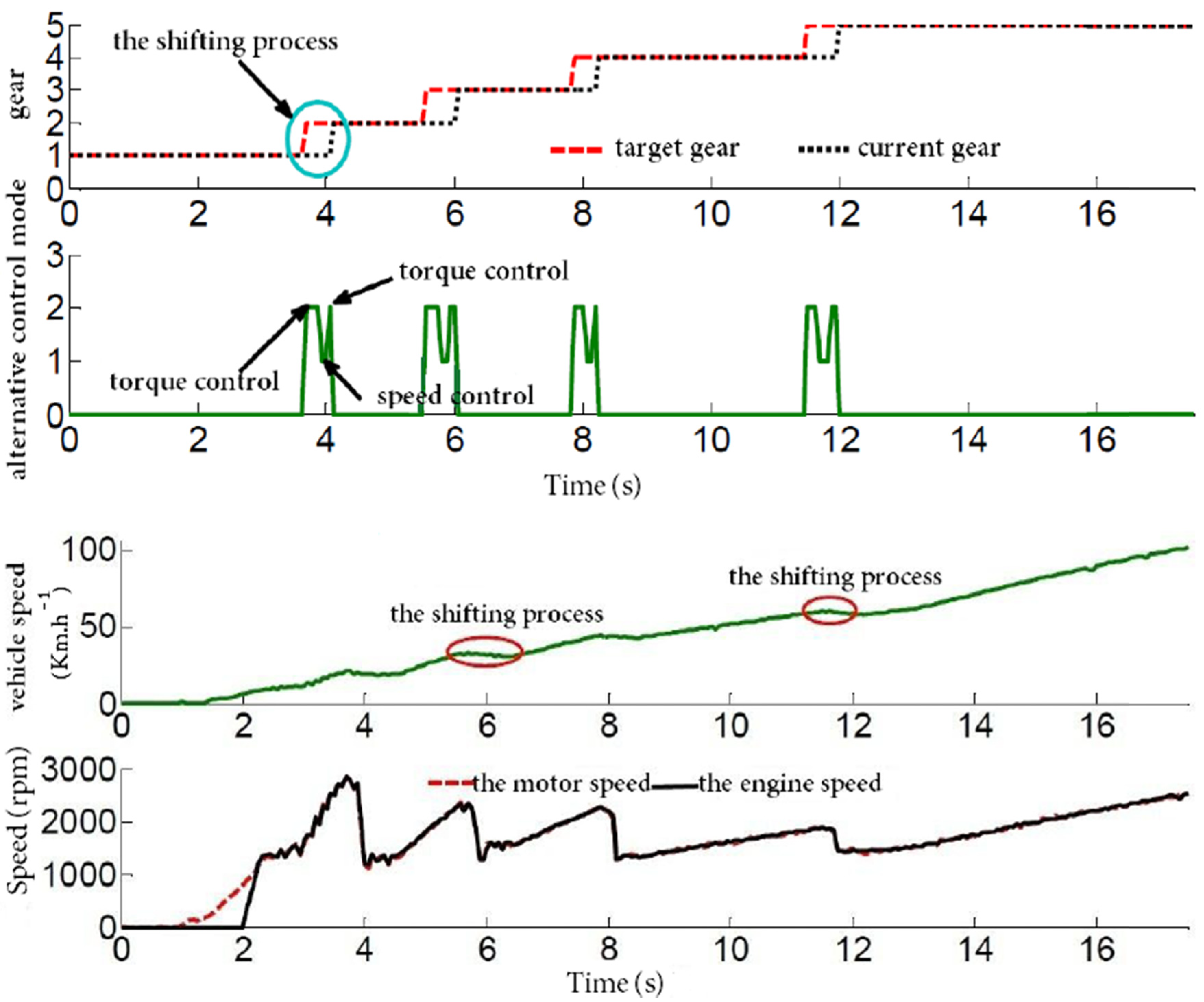
6. Simulation Analysis

| Parameters | Value |
|---|---|
| Unloaded/full load gross mass m/kg | 1320/1845 |
| Air resistance coefficient Cd | 0.36 |
| Frontal area A/m2 | 2.53 |
| Tire radius r/m | 0.299 |
| Main reducer ratio i0 | 3.894 |
| Transmission ratio (AMT-5 gears) | [3.615 2.042 1.257 0.909 0.902; 4.298] |
| Engine displacement/L | 1.124 |
| Maximum power (kW)/speed (r/min) | 58/6000 |
| Maximum torque (Nm)/speed (r/min) | 101/4000 |
| Motor | Permanent magnet synchronous motor |
| Rated/peak power (kW) | 18/35 |
| Rated/peak torque (Nm) | 86/167 |
| Battery | Lithium ion battery |
| Capacity (Ah)/Rated voltage (V) | 40/360 |


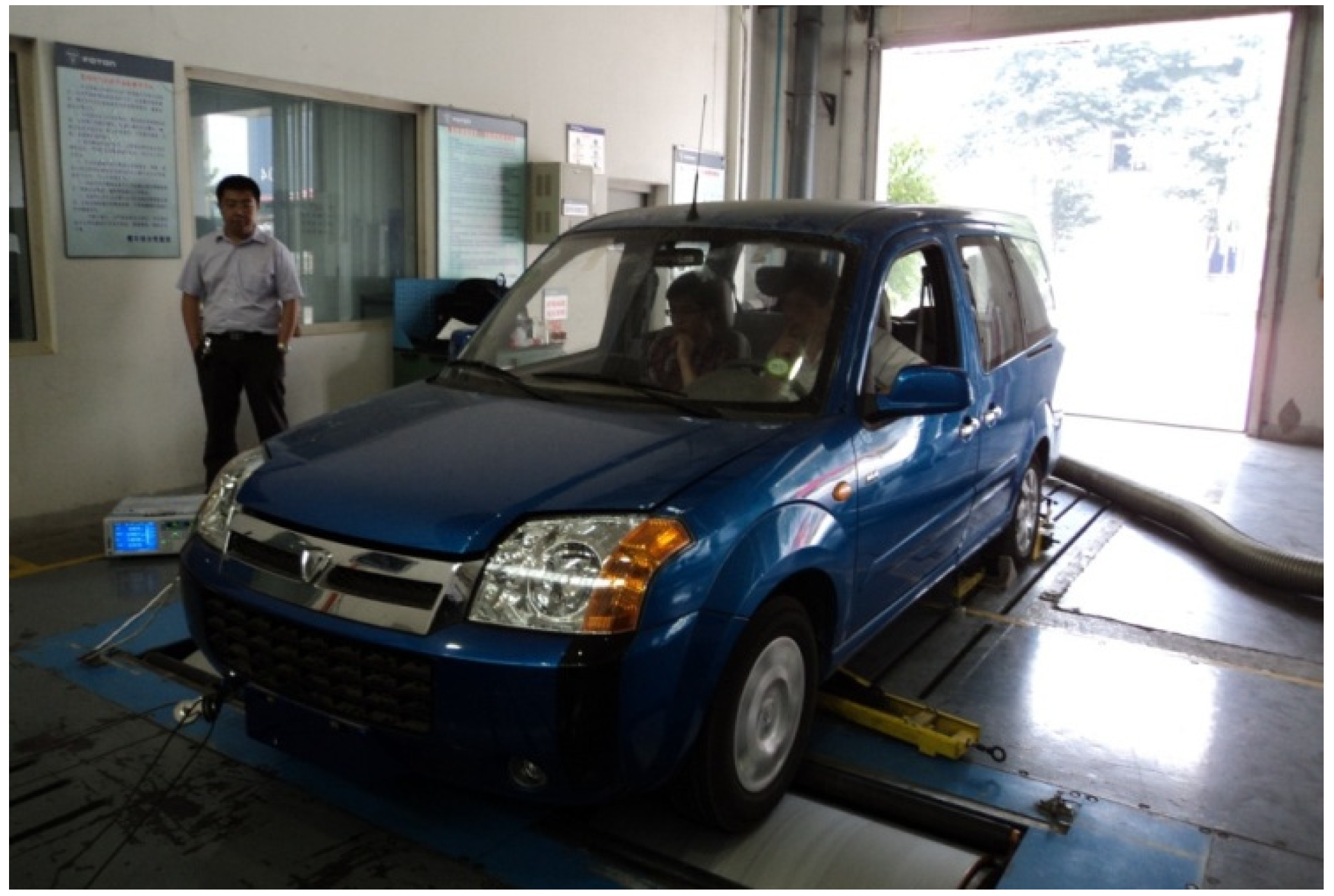
7. Real Car Test and Test Result Analysis

8. Conclusions
Acknowledgments
References
- Samaras, C.; Meisterling, K. Life cycle assessment of greenhouse gas emissions from plug-in hybrid vehicles: Implications for policy. Environ. Sci. Technol. 2008, 42, 3170–3176. [Google Scholar] [CrossRef] [PubMed]
- He, H.W.; Xiong, R.; Chang, Y.H. Dynamic modeling and simulation on a hybrid power system for electric vehicle applications. Energies 2010, 3, 1821–1830. [Google Scholar] [CrossRef]
- Xiong, R.; He, H.W.; Sun, F.C.; Zhao, K. Online estimation of peak power capability of Li-Ion batteries in electric vehicles by a hardware-in-loop approach. Energies 2012, 5, 1455–1469. [Google Scholar] [CrossRef]
- Baraszu, R.C.; Cikanek, S.R. Torque Fill-In for an Automated Shift Manual Transmission in a Parallel Hybrid Electric Vehicle. In Proceedings of the American Control Conference, Anchorage, AK, USA, 8–10 May 2002; pp. 1431–1436.
- Jo, H.S.; Park, Y.I.; Lee, J.M.; Lee, H.-D.; Sul, S.-K. A development of an advanced shift control algorithm for a hybrid vehicles with automated manual transmission. Int. J. Heavy Veh. Syst. 2000, 7, 281–298. [Google Scholar] [CrossRef]
- Liao, C.L.; Zhang, J.Z.; Lu, Q.C. Coordinated powertrain control method for shifting process of automated mechanical transmission in the hybrid electric vehicle. Chin. J. Mech. Eng. 2005, 41, 37–41. [Google Scholar] [CrossRef]
- Pettersson, M.; Nielsen, L. Gear shifting by engine control. IEEE Trans. Control Syst. Technol. 2000, 8, 495–507. [Google Scholar] [CrossRef]
- Lu, X.T.; Hou, G.Z. Introduction of the AMT control system structure and main foreign AMT products. Chin. Automob. Technol. 2004, 5, 19–22. [Google Scholar]
- Ye, M.; Qin, D.T.; Liu, Z.J. Shift performance control for mild hybrid electric vehicle equipped with automatic manual transmission. Chin. J. Mech. Eng. 2009, 45, 108–114. [Google Scholar] [CrossRef]
- Zhong, Z.; Kong, G.; Yu, Z. Shifting control of an automated mechanical transmission without using the clutch. Int. J. Automot. Technol. 2012, 13, 487–496. [Google Scholar] [CrossRef]
- Glielmo, L.; Iannelli, L.; Vacca, V. Gearshift control for automated manual transmissions. IEEE/ASME Trans. Mechatron. 2006, 11, 17–26. [Google Scholar] [CrossRef]
- Galvagno, E.; Velardocchia, M.; Vigliani, A. Dynamic and kinematic model of a dual clutch transmission. Mech. Mach. Theory 2011, 46, 794–805. [Google Scholar] [CrossRef]
- Kulkarni, M.; Shim, T.; Zhang, Y. Shift dynamics and control of dual-clutch transmissions. Mech. Mach. Theory 2007, 42, 168–182. [Google Scholar] [CrossRef]
- Lin, C.C.; Peng, H.; Grizzle, J.W. Power management strategy for a parallel hybrid electric truck. IEEE Trans. Control Syst. Technol. 2003, 11, 839–849. [Google Scholar] [CrossRef]
- Zhang, Y.; Chen, X.; Zhang, X. Dynamic modeling and simulation of a dual-clutch automated lay-shaft transmission. J. Mech. Des. 2005, 127, 302–307. [Google Scholar] [CrossRef]
© 2012 by the authors; licensee MDPI, Basel, Switzerland. This article is an open access article distributed under the terms and conditions of the Creative Commons Attribution license (http://creativecommons.org/licenses/by/3.0/).
Share and Cite
He, H.; Liu, Z.; Zhu, L.; Liu, X. Dynamic Coordinated Shifting Control of Automated Mechanical Transmissions without a Clutch in a Plug-In Hybrid Electric Vehicle. Energies 2012, 5, 3094-3109. https://doi.org/10.3390/en5083094
He H, Liu Z, Zhu L, Liu X. Dynamic Coordinated Shifting Control of Automated Mechanical Transmissions without a Clutch in a Plug-In Hybrid Electric Vehicle. Energies. 2012; 5(8):3094-3109. https://doi.org/10.3390/en5083094
Chicago/Turabian StyleHe, Hongwen, Zhentong Liu, Liming Zhu, and Xinlei Liu. 2012. "Dynamic Coordinated Shifting Control of Automated Mechanical Transmissions without a Clutch in a Plug-In Hybrid Electric Vehicle" Energies 5, no. 8: 3094-3109. https://doi.org/10.3390/en5083094