1. Introduction
Much attention has been paid to sequestration of CO
2 in saline aquifers, coal beds, and abandoned petroleum reservoirs as a way to curb atmospheric greenhouse effects [
1,
2,
3,
4,
5]. Specifically, there is interest in storing CO
2 in gas hydrates on the ocean floor [
6] as hydrates can provide a secondary storage method for CO
2 in the ocean, thereby minimizing a chance for stored CO
2 leakage [
7].
The chemistry associated with CO
2 hydrate formation is as follows: hydrates are inclusion compounds in which a hydrogen-bonded water cage confines a molecule of CO
2. Hydrate cages are held together by weak van der Waals forces that reduce the free energy of the compound, making it stable at low temperatures and high pressures [
8]. Sequestration of CO
2 as a hydrate is, therefore, an attractive method.
Ohgaki
et al. [
9] devised the idea of simultaneously storing CO
2 while extracting CH
4 from deep ocean sediments. The idea is based on the premise that replacing CH
4 gas with CO
2 is a favorable process which will maintain seafloor stability during and after the CH
4/CO
2 exchange, thus minimizing disturbance to the natural environment. Two factors contribute to this hypothesis: (1) structurally, CH
4 and CO
2 gases are similar—both are classified as structure I (sI) hydrate, which consist of two pentagonal dodecahedra (5
12) cages and six tetrakaidecahedra (5
126
2) cages [
8] and (2) hydrates of CO
2 are more thermodynamically stable than CH
4 at temperatures below 10ºC [
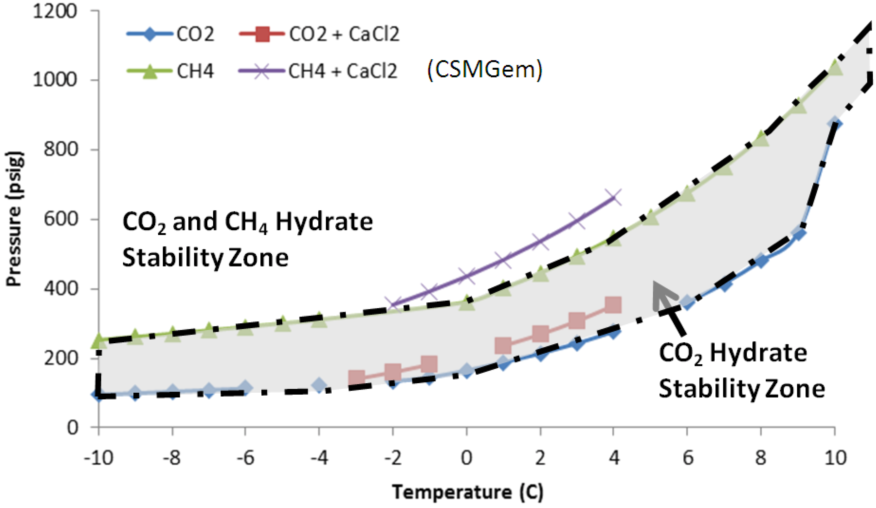
10]. The phase diagram of CO
2 and CH
4 hydrates in
Figure 1 shows the stability zones of both hydrates. As seen in Equations (1) and (2), no additional energy is needed to dissociate CH
4 hydrates, since CO
2 hydrate formation is exothermic and the heat of formation of CO
2 hydrates is enough to dissociate CH
4 hydrates, the latter releases free CH
4 [
6]:
Figure 1.
Hydrate stability curves for CO2 and CH4 gases.
Figure 1.
Hydrate stability curves for CO2 and CH4 gases.
CO
2 molecules prefer the larger 5
126
2 cages while CH
4 molecules fit easily in the smaller 5
12 cages. This way, when CO
2 is introduced into the CH
4 hydrate zone, not all of the CH
4 dissociates from its parent hydrate. Lee
et al. [
11] found that nearly 64% of methane gas could be extracted from methane hydrates of composition CH
4 6.05·H
2O. In addition, the reverse reaction, CH
4 gas replacing CO
2 in hydrates, is very slow, so the potential for reformation of CH
4 hydrates is low. CO
2, in general, is thermodynamically a better guest molecule than CH
4 [
11].
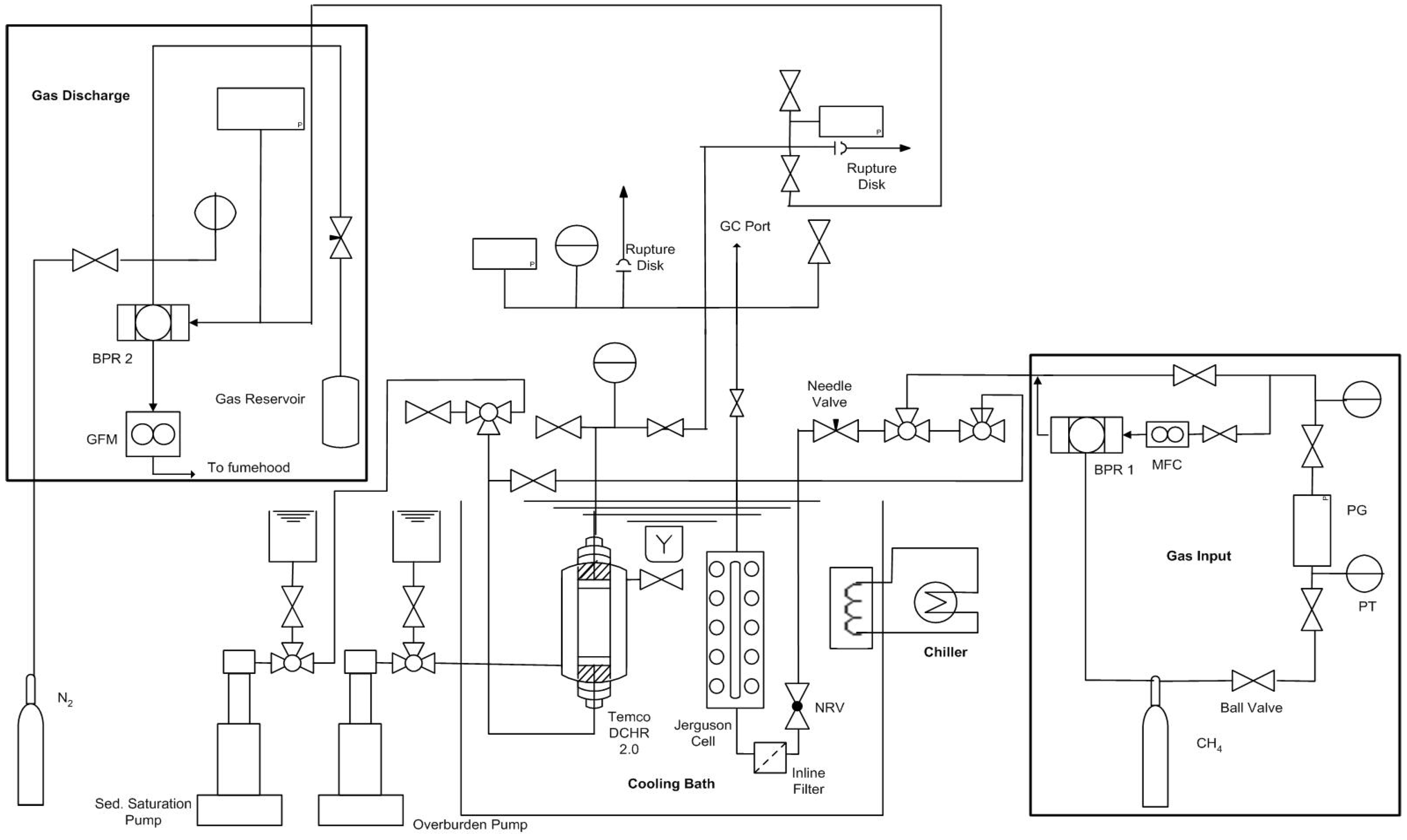
However, there are many issues that have not been addressed in previous studies. This study focused on the formation of gas hydrates on macroscale, from pure CO2 and mixed gases (CO2-CH4 mixture) in the presence of sodium dodecyl sulfate (SDS), a commonly used hydrate former. Of particular focus was quantitative hydrate formation and decomposition data collection to establish hydrate formation kinetics, P/T stability, and preferential hydrate formation in both pure and mixed gases. Since the pressure vessel in the experimental unit used was fitted with glass windows along the length, time resolved images also complemented this study. Such data would be a useful addition to the CO2/CH4 exchange data already known in literature.
3. Results and Discussion
A series of hydrate formation runs were performed to study the stability of CO
2 hydrates in a water-SDS solution at ~−1 °C.
Table 1 lists experimental Pressure/Temperature (P/T) conditions, theoretical yields, and actual percent conversions achieved.
Table 1.
Experimental Conditions and Results from Runs in the FISH unit. (Liquid volume: 75 mL of 300 ppm SDS Solution). * Recharge after Run 1.
Table 1.
Experimental Conditions and Results from Runs in the FISH unit. (Liquid volume: 75 mL of 300 ppm SDS Solution). * Recharge after Run 1.
| Run # | Gas | Texp (°C) | Charge # | Initial Pressure (psig) | Pressure Drop (∆) (psi) | Measured Conversion (%) | Theoretical Conversion (%) |
|---|
| 1 | CO2 | −1 | 1 | 425 | 132 | 30.0 | 63.6 |
| 2 | 503 | 170 | 32.8 | 69.0 |
| 2 | CO2 | −1 | * | 590 | 140 | 23.2 | 73.5 |
| 3 | CO2 | −2 | 1 | 449 | 152 | 32.8 | 67.9 |
| 2 | 512 | 44 | 8.4 | 71.7 |
| 4 | CH4-CO2 | −1 | 1 | 992 | 427 | 42.4 | 77.6 |
| (62%–38%) |
| 5 | CH4-CO2 | −1 | 1 | 1004 | 603 | 59.2 | 77.9 |
| (62%–38%) |
These high pressure and low temperature conditions resulted in CO2 hydrates that were observed from gas absorption and visual monitoring through the glass window on the cell. It is thermodynamically clear that gas hydrates formed as the system pressure decreased below the pressure that the system should have remained at for the given temperature conditions.
The volume ratio of gas/water was 1.67 in the cell. The gas/water ratio was maintained to keep experimental conditions in which water, not gas, was in excess. The steps leading to % conversion data are as follows. The first gas charging in Run 1 led to a 30% conversion of CO
2 into hydrates after about 67 h (
Figure 3).
Figure 3.
P/T versus time data plot during gas charging and hydrate formation in Run 1. Cell volume: 198 mL; Water: 75 mL; SDS: 300 ppm; Bath T: +5 °C; Actual cell T: −1 °C; Initial charging P: 425 psig (charge #1); Charge #2: 503 psig.
Figure 3.
P/T versus time data plot during gas charging and hydrate formation in Run 1. Cell volume: 198 mL; Water: 75 mL; SDS: 300 ppm; Bath T: +5 °C; Actual cell T: −1 °C; Initial charging P: 425 psig (charge #1); Charge #2: 503 psig.
After charging, the initial cell pressure drop from 425 psig to 390 psig was attributed to gas cooling inside the cell. Any further pressure drop under isothermal conditions was attributed to hydrate formation. In the case of Run 1, a total pressure drop of 132 psig was observed over a period of 55 h at −1 °C. After this time period, the cell pressure remained constant over 15 h. At this time after the first charge dropped to below 300 psig, the cell was repressurized to 503 psig at −1 °C. The pressure again dropped, this time to about 344 psig, which remained constant for over 24 h. This second charging resulted in a 33% conversion of CO
2 into hydrates. The cooling was then discontinued and the entire cell was warmed to room temperature.
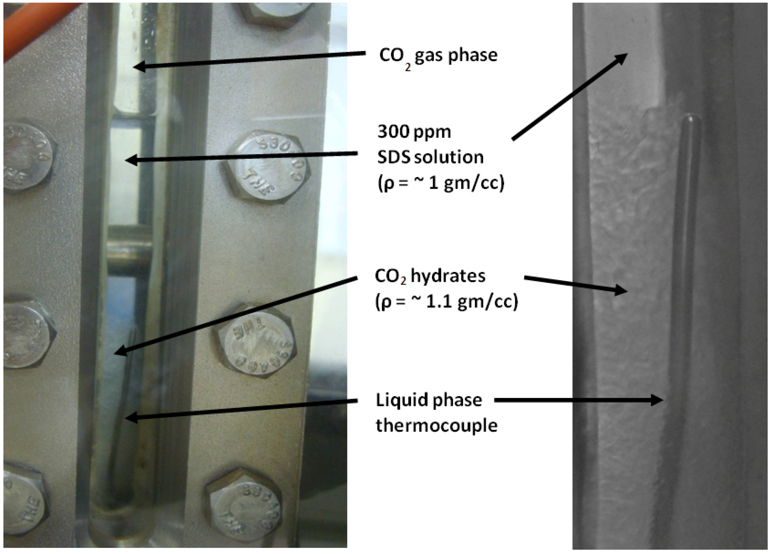
Figure 4 is an image taken after CO
2 hydrates were viewed at the bottom aqueous phase of the cell at around 96 h into the experiment.
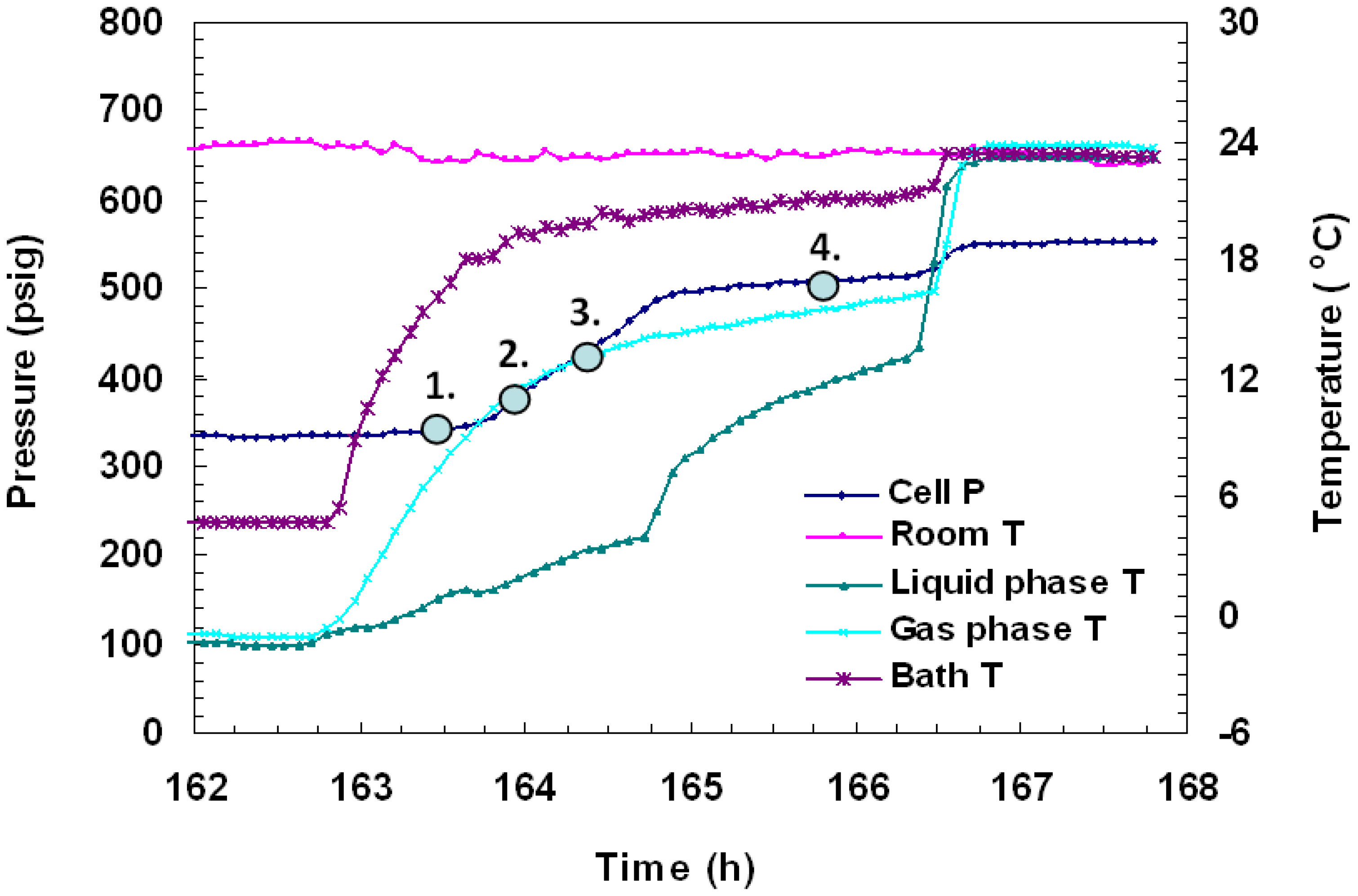
Figure 5 is a close up of formation cell P/T against time. The images shown in
Figure 6 were taken during CO
2 hydrate formation and their thermally induced dissociation. During dissociation, gas bubbles were seen to form uniformly throughout the viewing area in ice pockets as hydrates reverted back to water and CO
2 was released.
Figure 4.
CO
2 Hydrates formed during Run 1. The run conditions are shown in
Figure 3. The image on the right is a close up of the hydrates shown in the reactor on the left.
Figure 4.
CO
2 Hydrates formed during Run 1. The run conditions are shown in
Figure 3. The image on the right is a close up of the hydrates shown in the reactor on the left.
Figure 5.
P/T
versus time data plots during dissociation by thermal stimulation for Run 1. The run conditions are shown in
Figure 3.
Figure 5.
P/T
versus time data plots during dissociation by thermal stimulation for Run 1. The run conditions are shown in
Figure 3.
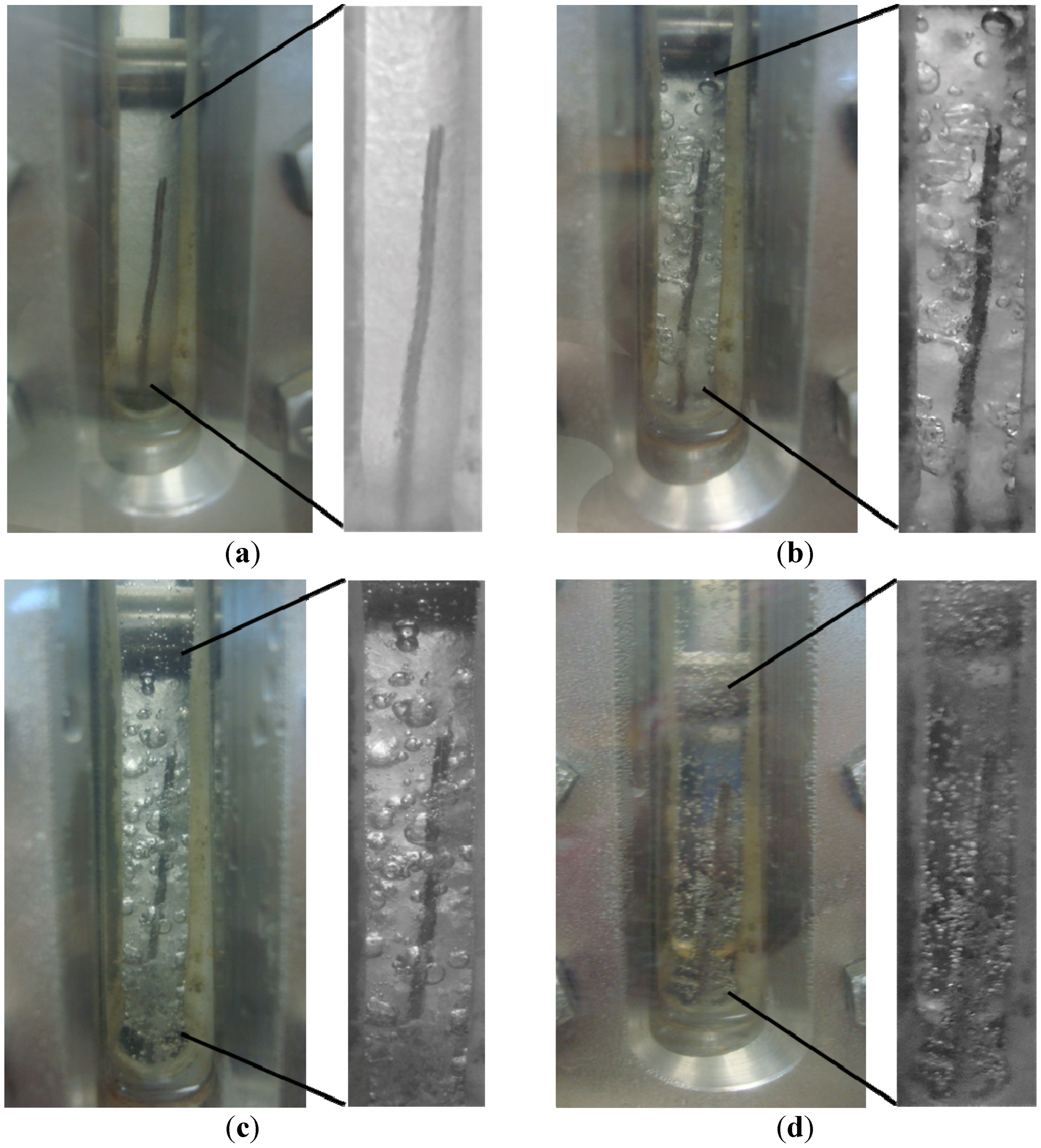
Figure 6.
Time resolved visual observations of the CO
2 hydrate phase during Run 1 at (
a) 339 psig, 5.46 °C; (
b) 369 psig, 1.62 °C; (
c) 428 psig, 12.98 °C; (
d) 508 psig, 15.28 °C. These letters correspond to the numbered P/T conditions shown in the dissociation plot of
Figure 5 where point 1 in
Figure 5 represents (a) shown below. CO
2 hydrates (density 1.1 g/cc) were observed to have an ice-like appearance in the aqueous phase at temperatures above the freezing point of a water-SDS solution.
Run 2 was performed using the same CO
2 gas and 300 ppm SDS solution that was used in Run 1. Once the cell warmed up to room temperature and all CO
2 hydrates formed during Run 1 had dissociated (no more gas evolution was observed), 40 psi of additional CO
2 gas was added to the system to thoroughly mix the gas/liquid phases inside the cell. Over nine days, the initial cell pressure of 590 psig slowly dropped to 450 psig while the cell temperature was held at −1 °C. At this time, the cell was warmed to increase the temperature to +1 °C (to melt any ice that had formed), leaving only CO
2 hydrates in the cell. A total pressure drop of 140 psig resulted in a hydrate conversion of 23%. Hydrates were observed in the cell, similar to those shown in
Figure 4 and
Figure 6 for Run 1.
Figure 7(a) shows cell the P/T against time data for the entire Run 2.
After the hydrate formation event in Run 2 was complete, the cell was depressurized. The SDS solution used in the previous run was left in the cell and used again in Run 3, and the cell was pressurized to 449 psig with fresh CO
2. After charging, the initial cell pressure drop from 449 psig to 297 psig was attributed to gas cooling inside the cell and hydrate formation. The first gas charging in Run 3 led to a 33% conversion of CO
2 into hydrates as shown in
Figure 7(b). A total pressure drop of 152 psig was observed over a period of 42 h at −2 °C. After this time period, the cell pressure remained constant over 30 h. At this time, the cell was repressurized to 512 psig at −2 °C. The initial pressure drop was due to cell cooling but once isothermal conditions were attained, the pressure drop was attributed to hydrate formation. After a total of 144 h, the temperature of the cell was raised to +2 °C to ensure hydrate rather than ice formation. When the temperature was raised above freezing, pressure continued to drop, indicating further hydrate formation until the cell warmed to room temperature. This second charging event only resulted in a hydrate conversion of 8%. Hydrates were visually observed in the cell, similar to those observed during Run1 (
Figure 4 and
Figure 6).
Figure 7.
Cell P/T versus Time data plots for: (a) Run 2 at −1 °C and 590 psig; (b) Run 3 at −2 °C and 512 psig.
Figure 7.
Cell P/T versus Time data plots for: (a) Run 2 at −1 °C and 590 psig; (b) Run 3 at −2 °C and 512 psig.
Recharging runs 1 and 3 with CO
2 showed an additional 32% and 8% gas conversion into hydrates respectively. This is expected because these were water-excess systems. Initially, 0.16 to 0.23 moles of CO
2 were charged into the cell while 4.17 moles of solution were present. The ratio for our system of gas to solution is far below the 1/6.05 mole ratio of CO
2 to water needed for full cage occupancy for CO
2 hydrates. The higher charging pressure was found to result in a higher percentage conversion during charge #2 in Run 1 though a low hydrate formation during charge #2 in Run 3 may be due to poor gas-liquid mass transfer. Hydrates are usually found to nucleate at the gas-liquid interface [
12], but there is a potential that hydrates nucleated at the gas-liquid interface and then accumulated in the aqueous phase due to density differences between the aqueous phase (1 g/cc) and the CO
2 hydrates (1.1 g/cc). Hydrates have also been hypothesized to nucleate in the aqueous phase by “local structuring” or “labile clustering” [
13].
Of the runs with CO
2 (runs 1–3), Run 2 achieved the least conversion (~23%) of CO
2 into hydrates as the solution and CO
2 gas previously used in Run 1 was reused to form hydrates. SDS used as a promoter in these runs has a tendency to precipitate out of aqueous solutions. This was confirmed in a previous study by Lee
et al. [
14] in which a high concentration of SDS under higher pressures was found to precipitate out earlier than that at lower concentrations. The least conversion observed in Run 2 may be due to the precipitation of SDS after a cumulative 17 days for runs 1 and 2. Also, in this run, SDS precipitation seems to have inhibited the hydrate memory effect. In addition, Wu and Zhang [
15] have shown that if the hydrate depleted solution reaches temperatures above 25 °C, the memory effect will not occur. During dissociation, it is possible that the temperature of the cell reached 25 °C.
After successfully forming CO
2 hydrates, runs were conducted to form hydrates from a CH
4-CO
2 mixed gas system. In Run 4, a fresh 300 ppm SDS solution was injected into the cell. The pressure was increased to 380 psig with CO
2 gas, followed by 1000 psig with CH
4 gas, thus forming a mixed gas system. Hydrates were observed in about 2 days after cooling had begun, so the initial cell pressure drop from 992 psig to 810 psig was attributed to gas cooling inside the cell at −1 °C. Any further pressure drop under isothermal conditions was attributed to hydrate formation. Upon initial formation, the cell temperature was increased to +2 °C to thaw the ice phase and confirm hydrate stability and distinguish these from the ice phase. The cell was allowed to equilibrate and pressure remained constant around 750 psig for subsequent 4 days, after which a second drop in pressure was recorded, indicating further hydrate formation. This drop can be clearly seen in the P/T
versus time plot in
Figure 8. After about 3 h of formation, the pressure remained constant for next 24 h at 565 psig, following which the cell was warmed to room temperature. A simple recorded pressure difference and change in the number of moles of gas present in the cell at the end of formation were calculated to show that 42% of the initial gas converted into hydrates, though CO
2 and CH
4 were indistinguishable.
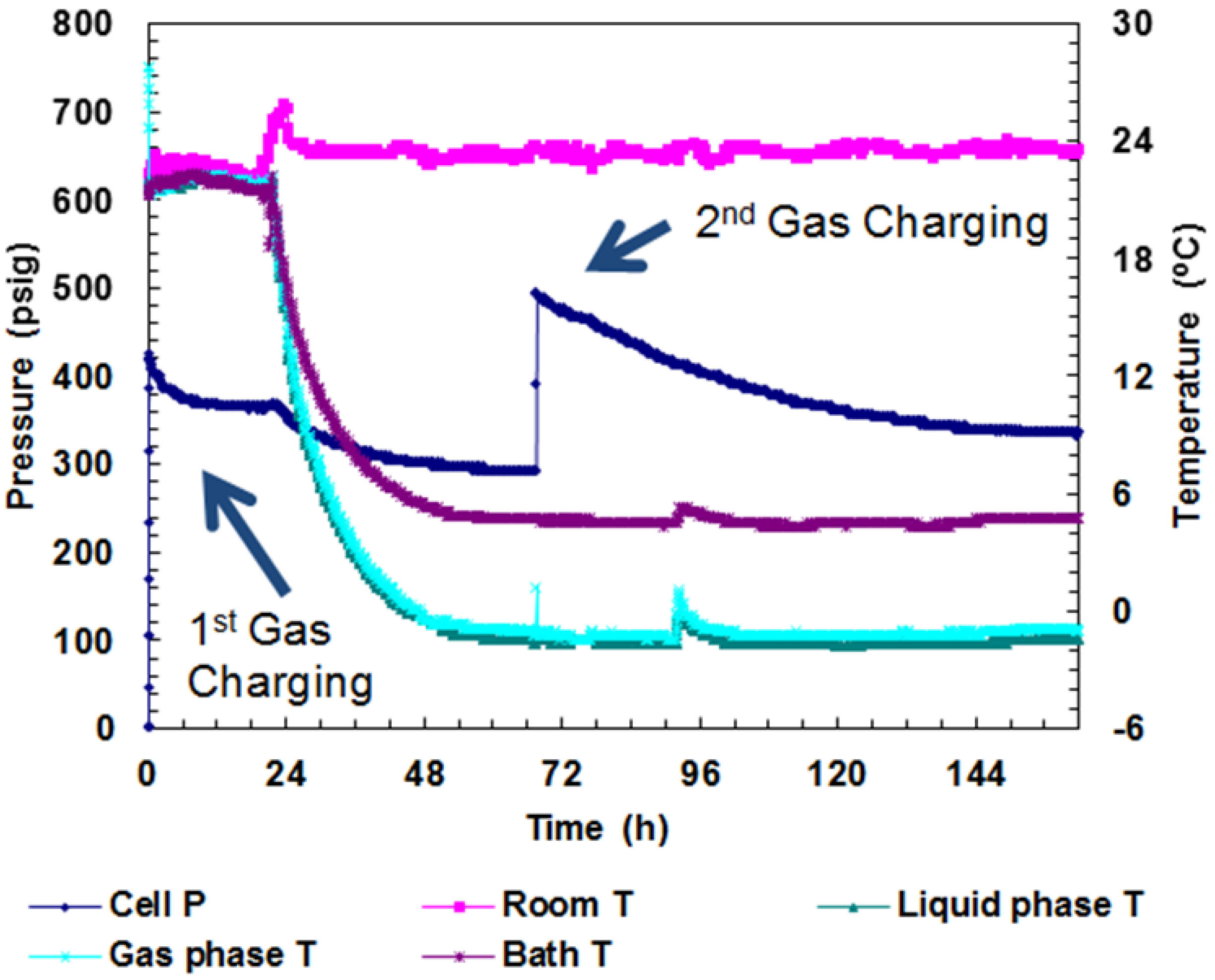
Figure 8.
A plot of P/T versus time during charging and hydrate formation in Run 4. Hydrate formation was achieved from a CH4-CO2 mixture. The embedded pink dots represent gas compositions measured by analyzing gas samples at corresponding times.
Figure 8.
A plot of P/T versus time during charging and hydrate formation in Run 4. Hydrate formation was achieved from a CH4-CO2 mixture. The embedded pink dots represent gas compositions measured by analyzing gas samples at corresponding times.
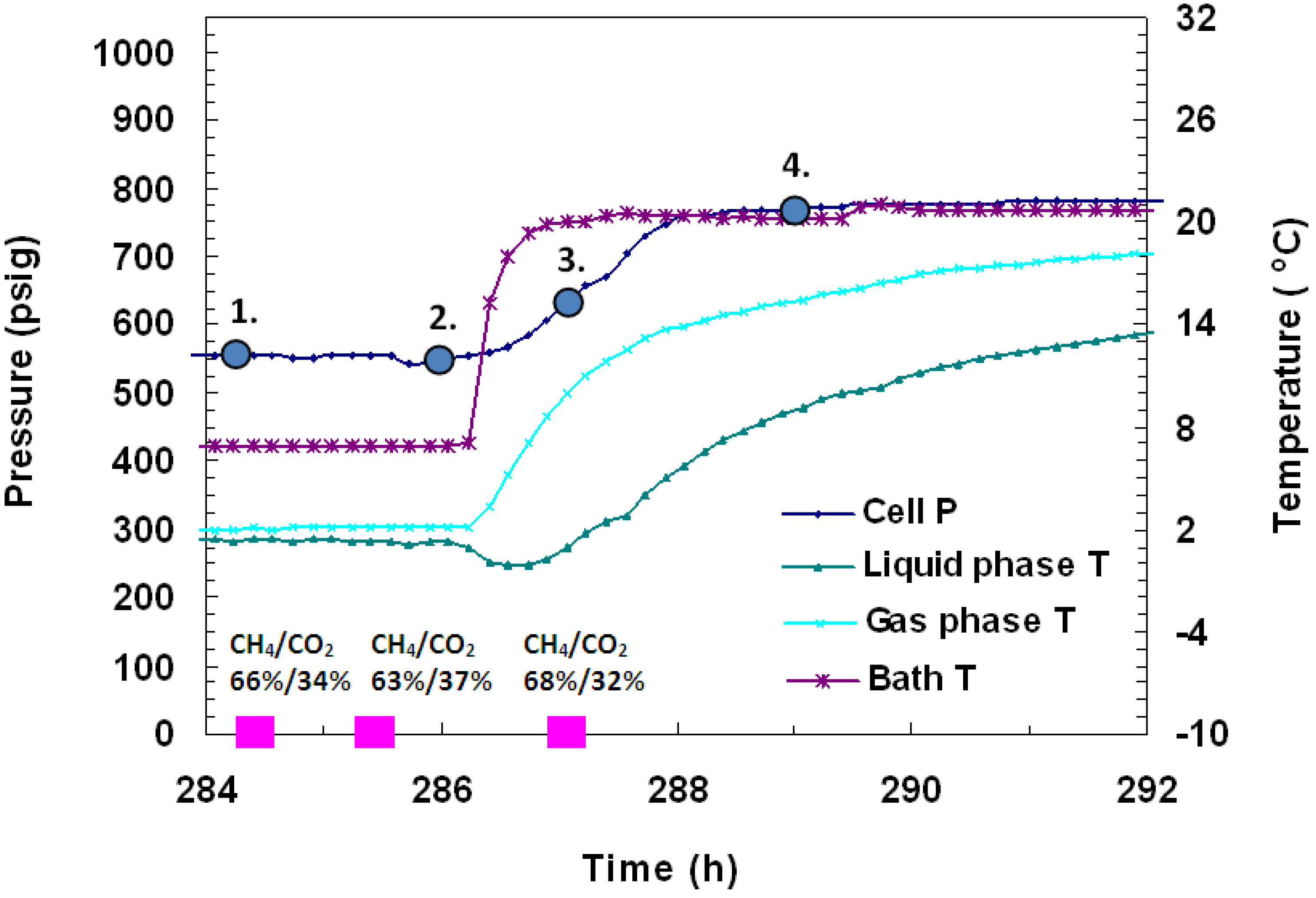
To discern the identity of hydrates, several gas samples (0.5 mL) were taken from the vessel and analyzed during formation and dissociation. The gas chromatographic (GC) data as %volume change from initial and final gas values for each gas are shown in
Figure 8 and
Figure 9. In
Figure 8, it was found that at 169 h into the experiment when cell pressure was 748 psig and cell temperature was +1 °C, the gas phase of the cell consisted of 12% CH
4 and 88% CO
2. Subsequently, 30 minutes later, under the same P/T conditions, another gas sample was taken and was found to be made up of 27% CH
4 and 73% CO
2. This indicates that initially, CH
4 hydrates form, but as formation continues in the cell, more CO
2 gas replaces CH
4 in hydrates. Following the second pressure drop, three more GC gas samples were taken in
Figure 9. The first gas sample, taken 284.5 h into the experiment at 568 psig and +1.4 °C, showed the gas composition as 66% CH
4/34% CO
2. One hour later, a sample taken at 567 psig and +1.3 °C showed the gas composition as 63% CH
4/37% CO
2. The last gas sample, taken 1.5 h after thermal stimulation had begun at 638 psig and +1 °C, showed gas as 68% CH
4/32% CO
2. Similar concentrations of CH
4 and CO
2 before and after formation were measured with GC analysis, which confirm similar relative % conversions for both gases. Embedded in
Figure 10 are images taken of the gas hydrates that formed in the vessel over time. The numbered points in
Figure 9 represent the conditions for the lettered images in
Figure 10 where point 1 in
Figure 9 corresponds to image (a) of
Figure 10.
Figure 9.
P/T against time during dissociation by thermal stimulation in Run 4. Hydrate formation was achieved from a CH4-CO2 mixture. The embedded pink dots represent gas compositions measured from gas samples analyzed in a Gow-Mac 580 series gas chromatograph.
Figure 9.
P/T against time during dissociation by thermal stimulation in Run 4. Hydrate formation was achieved from a CH4-CO2 mixture. The embedded pink dots represent gas compositions measured from gas samples analyzed in a Gow-Mac 580 series gas chromatograph.
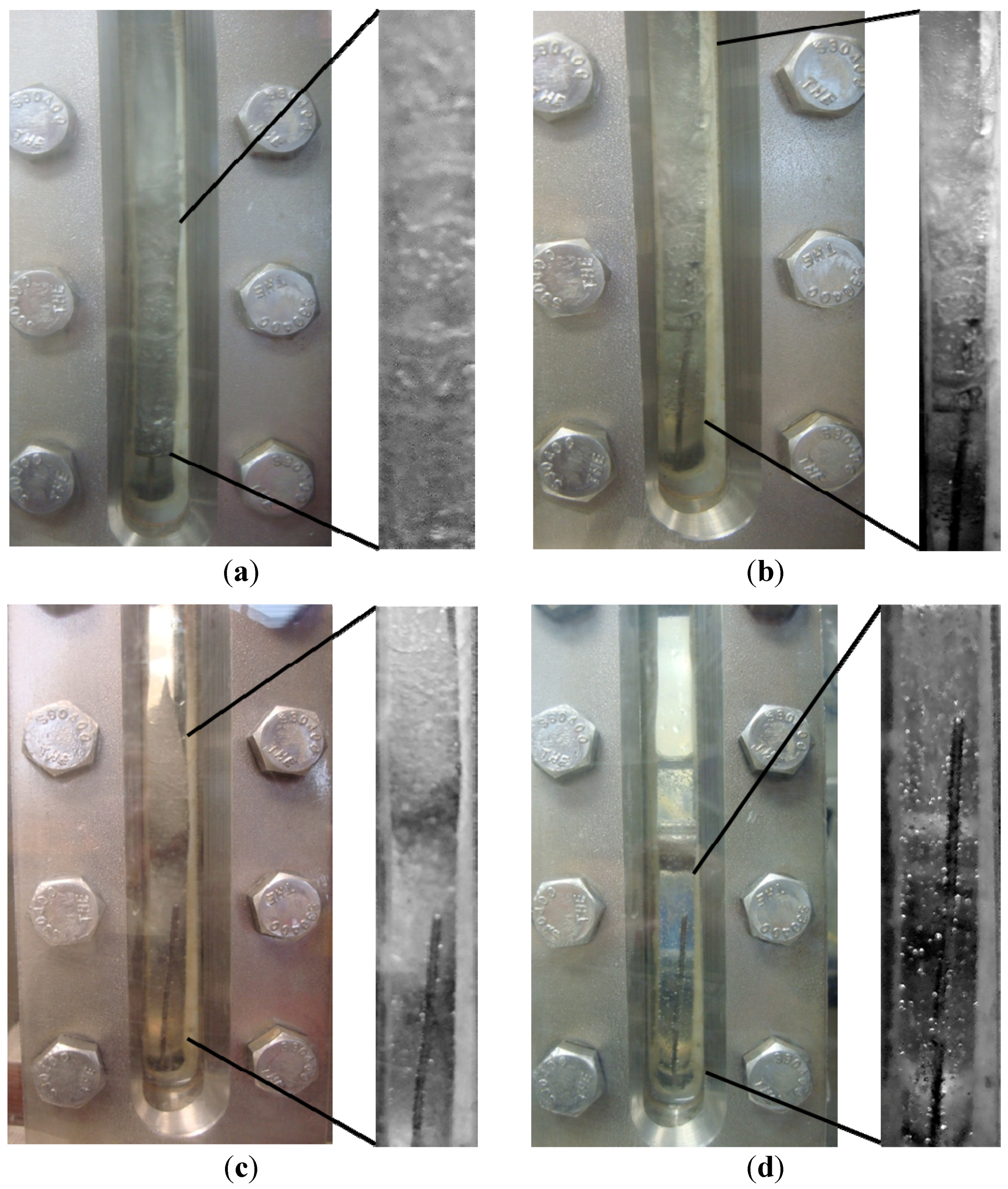
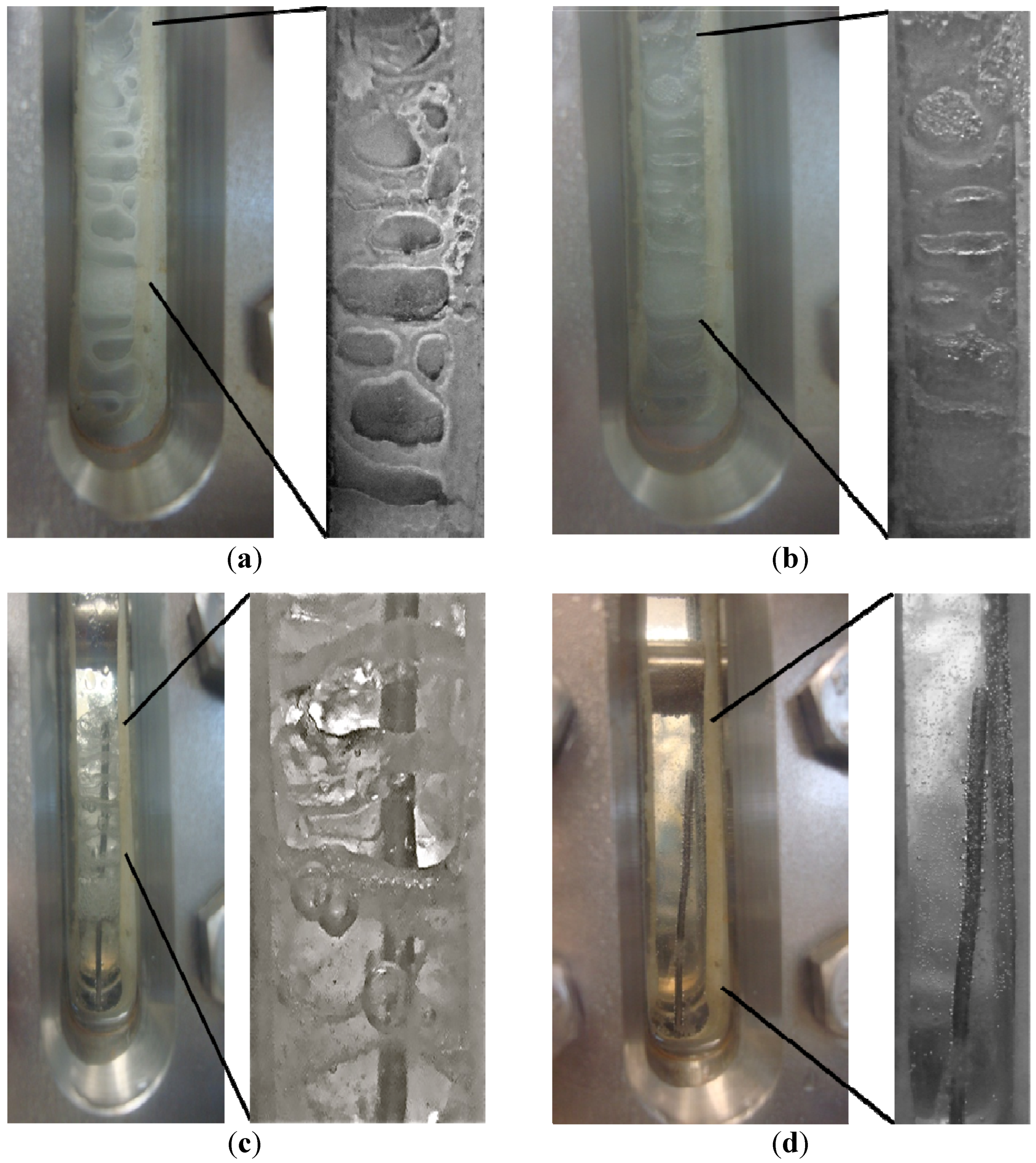
Figure 10.
Time-resolved observations of the CH
4-CO
2 hydrate formation at the end of formation and during dissociation in Run 4 at (
a) 574 psig, 1.38 °C; (
b) 559 psig, 1.34 °C; (
c) 629 psig, 0.77 °C; (
d) 770 psig, 8.92 °C. These P/T conditions correspond to the numbers shown in the dissociation plot of
Figure 9 where point 1 in
Figure 9 represents (a) shown below.
Run 5 was performed using the same procedure as described for Run 4. In this case, the cell was pressurized to 380 psig with CO
2 gas, followed by 1000 psig CH
4 gas. Hydrates formed a day after cell cooling began. As shown in
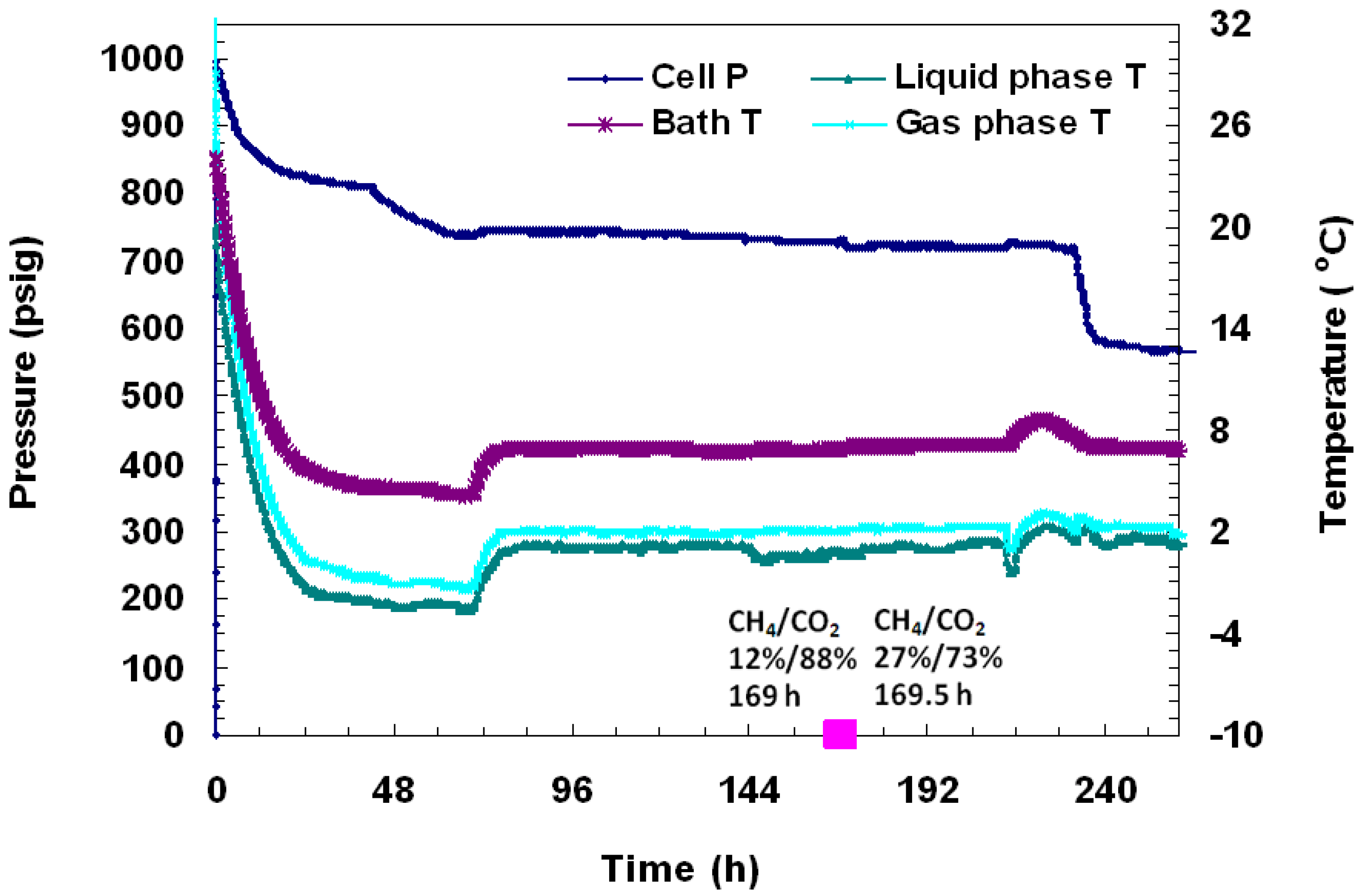
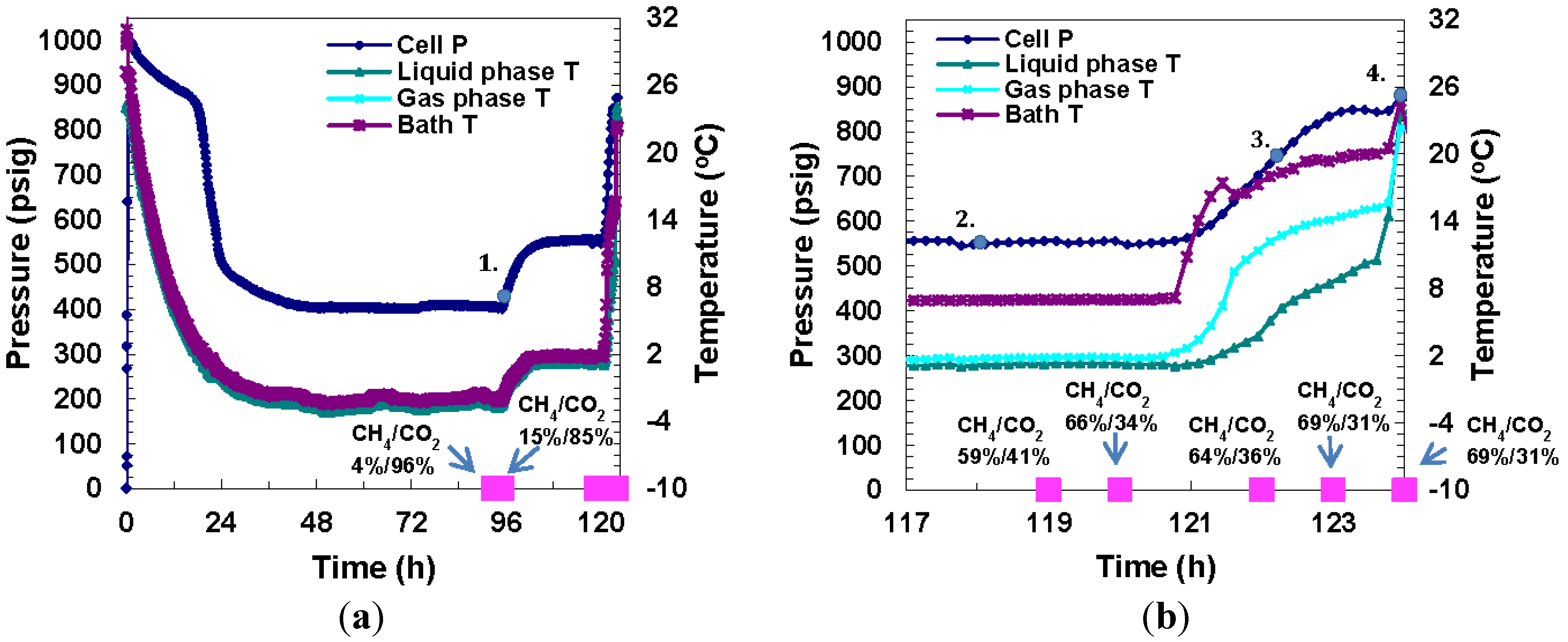
Figure 11, a pressure drop from 1004 psig to 880 psig due to cooling to −1 °C was observed over the first 24 h, followed by an abrupt pressure drop to 475 psig which was attributed to hydrate formation. A pressure of 410 psig was maintained for two days, after which the cell temperature was increased to +2 °C to confirm the presence of the hydrate phase. Once the cell was warmed above freezing, pressure remained stable at 565 psig for 24 h until the run ended. An overall gas conversion of 59% into hydrates was achieved.
Figure 11.
(a) A plot of P/T versus time during charging, formation, and dissociation from a CH4-CO2 mixture in Run 5; (b) A close-up view of hydrate dissociation by thermal stimulation. The embedded pink dots represent calculated gas compositions from gas chromatographic data.
Figure 11.
(a) A plot of P/T versus time during charging, formation, and dissociation from a CH4-CO2 mixture in Run 5; (b) A close-up view of hydrate dissociation by thermal stimulation. The embedded pink dots represent calculated gas compositions from gas chromatographic data.
As described for the previous run, several gas samples were analyzed during formation and dissociation to calculate individual % gas (CO
2 or CH
4) that converted to hydrates.
Figure 11 shows P/T
versus time plots and
Figure 12 shows images of gas hydrate formation over time for Run 5, a mixed gas system. In
Figure 11a, a gas sample was taken 94 h after the experiment had begun at 417 psig and −2.5 °C and the gas composition was measured to be 4% CH
4/96% CO
2. Two hours later, at 406 psig and −2.7 °C, the gas composition was 15% CH
4/85% CO
2. Similarly in Run 4, CH
4 hydrates were seen to form in the earlier stages of formation, and as time went by, more CO
2 hydrates formed. At this point, the cell temperature was raised to above freezing to ensure that the ice phase was not present in the cell. Five GC samples were taken prior to and during dissociation as shown in
Figure 11b, which is a close up of day five of the experiment. The gas compositions under P: 566 psig and T: +1.3 °C, at various time intervals were as follows: (1) Sample #1, Time: 119 h: 59% CH
4/41% CO
2; (2) Sample #2: Time: 120 h: 66% CH
4/34% CO
2. At this point, thermal stimulation was begun to bring about dissociation of formed hydrates. At 122 h, the temperature was 2.4 °C, the pressure increased to 644 psig and the gas analysis was: 64% CH
4/36% CO
2. At 123 h, the pressure was 811 psig at +7.7 °C and the corresponding gas analysis was: 69% CH
4/31% CO
2. At 124 h, the pressure had increased to 860 psig as the temperature increased to +10.2 °C but the gas analysis was unchanged. The numbered points in
Figure 11a and
Figure 11b represent P/T conditions in the cell when the lettered images in
Figure 12 were taken where point 1 in
Figure 11 corresponds to image (a) of
Figure 12.
The hydrate formation runs with 62% CH4/38% CO2 gas mixtures resulted in gas conversions as high as 42% and 59%. Hydrates from the CH4-CO2 mixture were found to grow uniformly throughout the cell as a massive structure. A solid structure in the form of hydrates was visually observed on the entire the viewing glass (1/2 in. × 12 in.). Dissociation was also observed randomly throughout the hydrate phase. Both CO2 hydrates and CH4 hydrates were indistinguishable in terms of morphology to the naked eye, so it is unknown if CO2 and CH4 hydrates or mixed gas hydrates formed.
It is apparent from the completed runs in the FISH unit that facile formation of both CO
2 and CH
4 hydrates was observed, under the P/T conditions used. It was found that, especially in the early stages of hydrate formation, a majority of the gas that was stored in hydrates was CH
4. Seo
et al. (2001) [
16] observed that at lower pressures, CO
2 preferentially forms hydrates. Uchida
et al. (2005) [
17] formed CH
4-CO
2 hydrates and found that when the gas phase consisted predominantly of CO
2, CH
4 preferentially forms hydrates in the early stages of hydrate formation. The observed data are consistent with these observations though merits further investigation to understand the implication in natural CH
4 hydrate reservoirs.
Figure 12.
Time resolved visual observations of the CH
4-CO
2 hydrate phase at the end of formation and during dissociation for Run 5 at: (
a) 460 psig, −1.05 °C; (
b) 564 psig, 1.24 °C; (
c) 635 psig, 2.44 °C; (
d) 848 psig, 10.25 °C. These P/T conditions correspond to the numbers shown in the dissociation plot of
Figure 11 where point 1 in
Figure 11 represents (a) shown below.

