1. Introduction
In recent years, the automotive industry has made great progress in improving engine efficiency and reducing pollutant emissions. However, on average, two thirds of the fuel energy is still wasted through the exhaust gases and the cooling liquid [
1]. Improving the use of the wasted energy, and mainly that of the exhaust gases, is therefore of great significance. There are several technologies for the recovery of the wasted energy of a combustion engine [
2]. Rankine cycle systems show a good potential for the waste heat recovery of light-duty trucks [
3,
4,
5,
6,
7] as well as passenger vehicles [
8,
9,
10,
11,
12,
13,
14]. One of the promising solutions is the steam Rankine system [
10,
11,
12,
13,
14,
15].
The performance of the Rankine cycle depends on the heat exchanger’s effectiveness as well as the pump and expander selection. The expander technology impacts the amount of mechanical power output produced by the Rankine cycle. An adequate choice of expander technology is based on its cost, targeted power output and the available room inside a vehicle. In order to choose the most suitable expander technology for a Rankine system application, a compromise has to be reached between these three criteria.
Badr
et al. [
16,
17,
18] discussed the different technologies of expansion machines for a steam Rankine cycle. Turbines, while widely used for Rankine cycles in industrial electricity production, are not appropriate for a small-scale Rankine cycle because of their low efficiency and large dimensions [
19]. Moreover, optimal turbine efficiency is achieved under steady operating conditions, whereas a vehicle operates mainly under transient conditions. Freymann
et al. [
11] tested the steam Rankine system with a two-stage impulse turbine without lubrication and reported a nominal power output of 2 kW. It seems that the internal leakages of the expansion device were reduced in comparison to the reaction turbines used in power plants. A further disadvantage of turbines is their relative cost, which increases as the size of the device decreases [
17].
Volumetric machines having a smaller size and higher efficiency than single-stage turbines are an alternative solution for a steam Rankine cycle [
20]. A Wankel machine for a heat recovery application was tested by Badr
et al. [
18]. The power output of the machine varied from 5 to 20 kW, depending on the operating conditions. However, the isentropic efficiency was very low (about 21%) with steam as the working fluid. In view of the size of the machine, it appears difficult to implement it in a vehicle.
The possibility of using vane expanders for a heat recovery application was also studied in [
17,
21,
22]. Using an organic working fluid, Badr
et al. [
17] obtained a power output of 1.8 kW, which corresponds to an isentropic efficiency of 73%. Ben-Bassat
et al. [
22] evaluated the performance of the two-stage rotary vane expander, and came to the conclusion that the 10% decrease in the expander power output was caused by both mechanical and heat losses.
Screw expanders offer a good potential for exhaust recovery by the Rankine cycle because of their compactness, and enable expansion within the two-phase zone [
17,
23]. To reduce friction losses, screw machines require lubrication. When water is used as the working fluid, the efficiency of these expanders is low because of the leakage due to the clearance between the screws and the casing [
23].
Scroll expanders are a promising technology for a Rankine cycle automotive application. Lemort
et al. [
24] tested and modelled a scroll expander and obtained a power output of 1.8 kW, which corresponds to an isentropic efficiency of about 68%. Clemante
et al. [
25] modelled a scroll expander using R245fa as the working fluid. This machine produced 1.2 kW of power output. The overall efficiency was 70%. Mathias
et al. [
26] compared a scroll expander and a gerotor machine for an automotive heat recovery application. Both machines performed well and were able to produce 2 to 3 kW of mechanical power.
If the pressure ratio on the expander is quite high, reciprocating machines are suitable. Reciprocating machines have a good isentropic efficiency (about 70%) and a good power output/size ratio. Moreover, they are more robust than scroll expanders. Demler [
27] and Badami
et al. [
28] suggested the use of a reciprocating machine for a waste heat recovery system. Endo
et al. [
13] studied an exhaust heat recovery Rankine system for an electric hybrid vehicle using a reciprocating piston expander.
This survey of Rankine cycle systems applied to passenger vehicles indicates that the reciprocating machine is the most promising technology for a waste heat recovery application. This technology is quite innovative in the automotive industry. In order to study the performance and operation of the reciprocating machine, a detailed steady-state simulation model of a piston expander is proposed in this paper. The model is validated and the performance study of the expansion machine is carried out.
2. Modelling of the Expander
The semi-empirical model of the reciprocating expander is based on the reciprocating compressor models of Winandy
et al. [
29] and Cuevas
et al. [
30]. The different modelling approaches to volumetric machines proposed by Touré [
31] were also applied to the development of the reciprocating machine steady-state model. The model was developed in the EES (Engineering Equation Solver) environment.
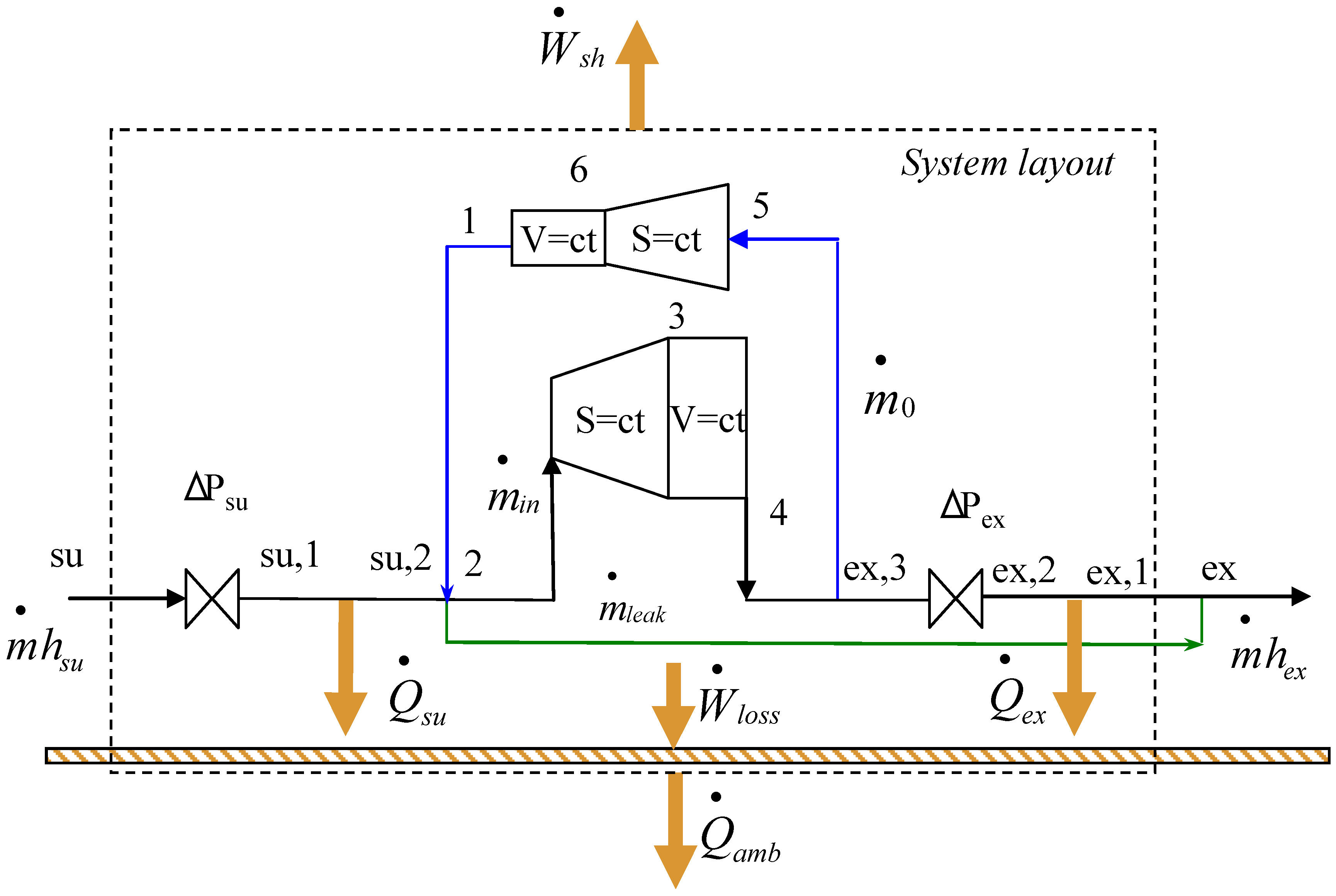
The scheme of the overall expander model is presented in
Figure 1. The model assumes that the evolution of the fluid inside the expander can be split into several consecutive steps. The fluid encounters a pressure loss during the suction process (su to su,1 on
Figure 1). It is then cooled down by contact with the metal housing of the machine (su,1 to su,2). The internal expansion process undergoes isentropic expansion (s = const) and an expansion at constant machine volume (V = const).
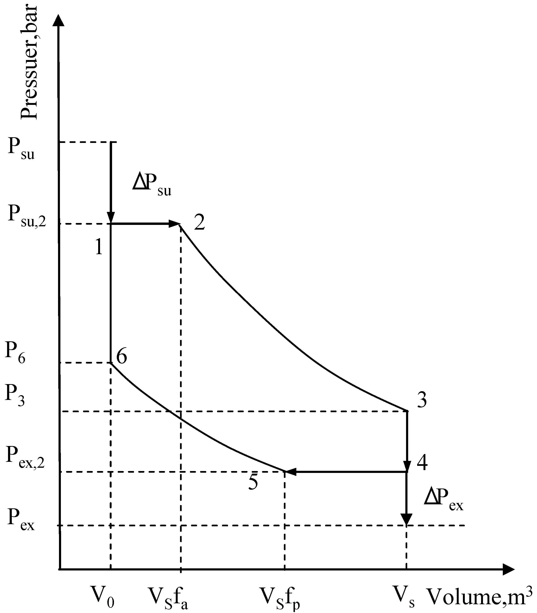
Figure 2 shows the evolution of the cylinder pressure with respect to its volume (pV diagram). This process contains under and over-expansion losses (evolution 2–3–4) as well as losses associated with the partial compression of the residual mass of fluid trapped inside the cylinders at the end of the discharge process (evolution 5–6–1). During the discharge process (
cf.,
Figure 1) the fluid is heated up by contact with the metal housing of the machine (ex,3 to ex,2) and also undergoes a pressure loss (ex,2 to ex,1). In the model, it is assumed that an internal leakage flow is directly linked from the expander supply to its exhaust (su,2 to ex).
Figure 1.
Schematic representation of the overall expander model.
Figure 1.
Schematic representation of the overall expander model.
Figure 2.
PV diagram representing the internal expansion process.
Figure 2.
PV diagram representing the internal expansion process.
In order to describe the expansion process, the following geometrical parameters of the expander were defined.
The duration of the supply
fa and exhaust
fp processes influence the mass flow rate swept by the expander. The duration of the supply process, or cut-off ratio (
fa), can vary between 0.1 and 0.25 [
28]. The volume of the admitted and residual fluids is determined in the model by Equation (1). According to the expander data provided by the manufacturer, the duration of the supply and exhaust processes can be 0.25 for a supply valve and 0.4 for an exhaust valve:
The values of the expander displacement VS and clearance volume V0 were taken from the expander manufacturer’s data. The ratio C between the clearance and the expander displacement is 0.072.
2.1. Supply and Exhaust Pressure Drops
The pressure drops within the supply and exhaust valves are computed by reference to the flow through a simple nozzle. For a compressible fluid, the stream velocity (subsonic or sonic flow) determines the pressure at the nozzle throat and depends on the critical pressure given by Equation (3):
The pressure at the throat is determined as the maximum pressure between the critical pressure
Pcrit and the exhaust pressure
Pex according to Equation (4):
The value of the perfect gas constant, gamma, is computed from Equation (5):
2.2. Mass Flow Rate
The internal mass flow rate depends on the displacement and the clearance volume of the expander and can be determined by Equation (6):
where
v2 is specific volume of the working fluid after closing of the supply valve, m
3/kg;
v6 isspecific volume of the working fluid before opening of the supply valve, m
3/kg.
During the operation of the reciprocating machine, different leakages were observed which result in an increase in the suction mass flow rate. The following equation describes the actual mass flow rate passing through the expander:
where
![Energies 05 01751 i008]()
—leakage mass flow rate, kg/s.
The leakage mass flow rate depends on the leakage area and thermodynamic parameters of the working fluid:
where
thr,leak—specific enthalpy of the fluid at the throat, J/kg;
hsu,2—initial specific enthalpy of the fluid, J/kg.
2.3. Expander Power Output
The internal power of the expander is the sum of the suction, expansion, discharge and compression mechanical powers:
where
![Energies 05 01751 i011]()
—compression work;
![Energies 05 01751 i012]()
—expansion work;
![Energies 05 01751 i013]()
—discharge work;
![Energies 05 01751 i014]()
—admission work.
The net power output depends on the value of the friction losses. The expander manufacturer provided the friction values for each value of the inner power of the expander:
2.4. Heat Transfer
The model takes into account the heat transfer between the expander housing and the working fluid, and that between the expander housing and the ambient air as well as heating-up due to mechanical losses. The thermal convection loss due to heat exchange between the expander metal housing at temperature T
w and fluid during suction can be evaluated from Equation (11):
where
AUsu—global heat transfer coefficient between working fluid and metallic envelope, W/K;
Tw—wall temperature, K.
The value of the
AUsu depends on the mass flow rate of the working fluid and is given by Equation (12) proposed by Lemort
et al. [
24]:
where
AUsu,n—nominal overall heat transfer coefficient estimated at nominal mass flow rate
![Energies 05 01751 i018]()
, W/K.
The exhaust heat losses can be described in a similar way. Heat losses to the ambient can be determined from the following equation:
where
AUamb—overall heat transfer coefficient between metallic envelope and the ambient, W/K.
Cuevas
et al. [
30] estimated the value of the
AUamb overall heat transfer coefficient.
Mechanical losses lead to the heating of the expander envelope. They are directly injected within the envelope (see
Figure 1). Thus, the thermal balance on the expander envelope enables the determination of its temperature
Tw and is given by Equation (14):
2.5. Efficiency
The performance of the expander can be assessed by its overall isentropic, volumetric and mechanical efficiencies.
The isentropic efficiency:
The volumetric efficiency:
The mechanical efficiency:
3. Validation of the Expander Model
Before evaluating the validity of the model, it must be calibrated. Calibration consists in identifying the values of the parameters that yield the minimum deviation between the performance given by the manufacturer and that predicted by the model. In the expander model, two types of parameters were identified. The geometrical parameters correspond to the displacement
Vs and clearance volume
V0. The operational parameters correspond to valve timing
i.e.,
fa and
fp, leakage
i.e.,
Aleak, suction and exhaust orifice areas
i.e.,
Asu and
Aex and overall heat transfer coefficients
i.e.,
AUsu,
AUex and
AUamb. The nominal values of these parameters are summarized in
Table 1. In order to achieve the performances given by the expander manufacturer, the operational parameters of the expander model have to be optimized.
Table 1.
Nominal parameters of the expander model.
Table 1.
Nominal parameters of the expander model.
| fa | fp | AUamb, W/K | AUex, W/K | AUsu, W/K | Aleak, m2 | dtrh,su,n, m | dthr,ex,n, m |
|---|
| 0.25 | 0.4 | 2.5 | 45 | 22.2 | 0.2386 × 10⁻⁶ | 6 × 10⁻⁶ | 11 × 10−6 |
In order to identify the optimal parameters of the expander the process proposed by Lemort
et al. [
24] was used. Thus, the values of the mass flow, the internal power output and exhaust enthalpy of the working fluid were computed by minimizing the overall error function [Equation (18)] for different operating conditions. Usually, when water is used as a working fluid, the expansion process ends at the two-phase zone. In that case, the estimation of exhaust enthalpy is needed. Experimental values were provided by the expander manufacturer:
where
![Energies 05 01751 i025]()
—mass flow rate given by the expander manufacturer, kg/s;
![Energies 05 01751 i026]()
—mass flow rate calculated by the model, kg/s;
![Energies 05 01751 i027]()
—internal power output given by the expander manufacturer, W;
![Energies 05 01751 i028]()
—internal power output calculated by the model, W;
![Energies 05 01751 i029]()
—exhaust enthalpy of the working fluid given by the expander manufacturer, J/kg;
![Energies 05 01751 i030]()
—exhaust enthalpy of the working fluid calculated by the model, J/kg.
Calibration of the expander simulation model was done at different operating conditions corresponding to the expander rotary speed varying from 500 to 6000 rpm, pressure ratio varying from 20 to 40, and fluid supply temperatures of 280, 300 and 320 °C. The values of the pressure ratio and expander supply temperature were estimated from the Rankine cycle model for exhaust gas recovery applications [
32].
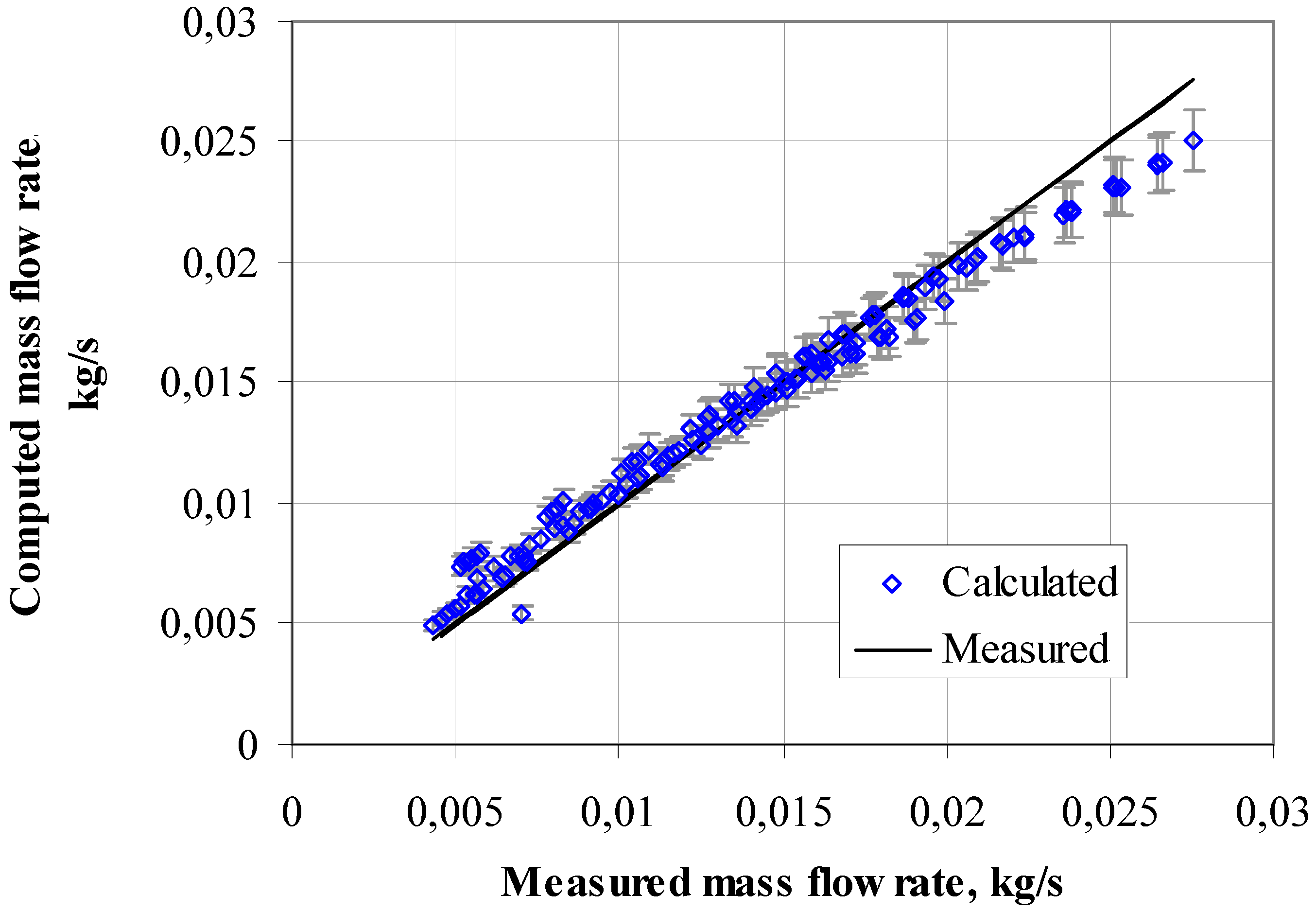
In order to observe the deviation of the computed values from the measured ones, two curves were plotted: one curve presents measured values as a function of itself; the other one presents computed values as a function of the measured one.
Figure 3 compares the evolution of the measured to the computed values of mass flow rates of the working fluid. The gray vertical line on
Figure 3 shows a deviation of 5%. It can be observed that the maximum deviation is 8%. The losses due to pressure drop at the supply nozzle influence the mass flow rate. Thus, the supply pressure drop increases with the rotation speed, causing the increase in deviation.
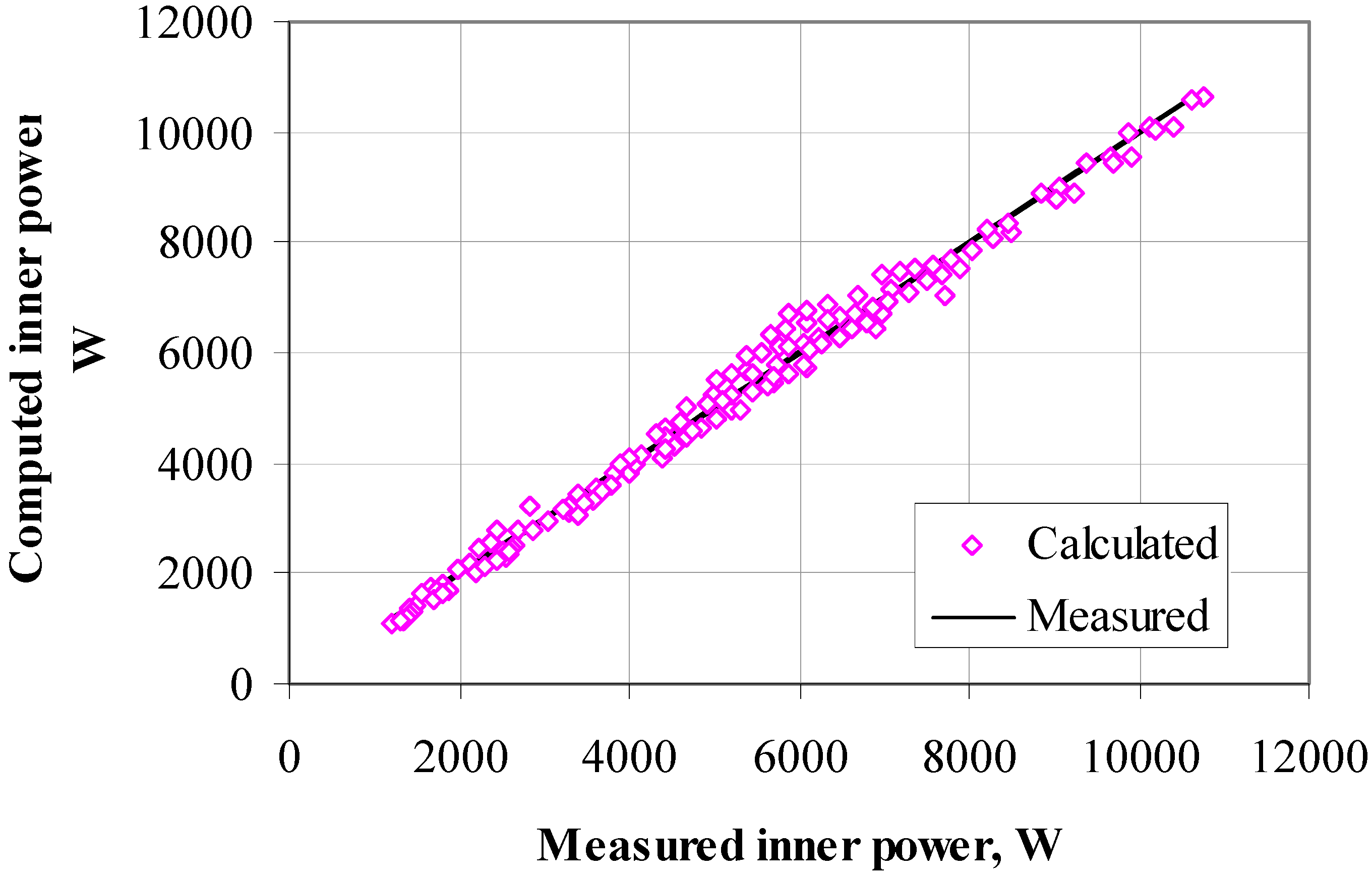
The overall error of the comparison between predicted and measured values of expander inner power output was 5.3% (
Figure 4).
Figure 3.
Comparison between calculated and measured mass flow rates of the expander.
Figure 3.
Comparison between calculated and measured mass flow rates of the expander.
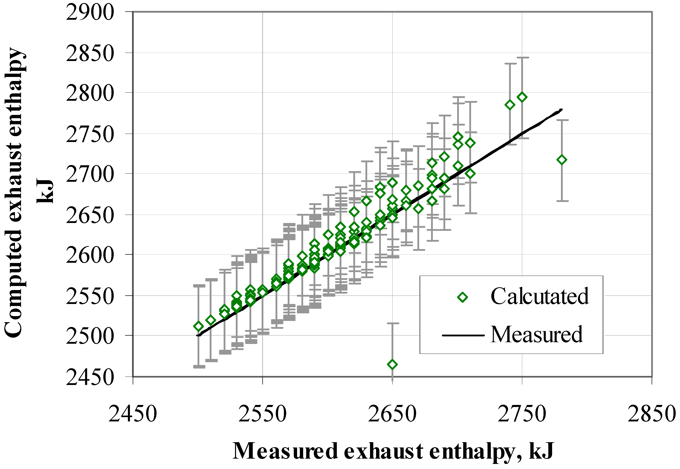
In the case of the end of the expansion process within the two-phase zone, it is necessary to evaluate the exhaust enthalpy of the working fluid. The measured specific exhaust enthalpy was computed using the exhaust temperature and steam vapor fraction data given by the expander manufacturer. It should be noted that the model overestimates the exhaust enthalpy but the overall error remains small: 0.75% (
Figure 5). In conclusion, the performance of the expander device was predicted with an overall accuracy of 4.7%.
Figure 4.
Comparison between calculated and measured internal power outputs of the expander.
Figure 4.
Comparison between calculated and measured internal power outputs of the expander.
Figure 5.
Comparison between calculated and real exhaust enthalpies of the working fluid.
Figure 5.
Comparison between calculated and real exhaust enthalpies of the working fluid.
4. Expander Analysis
The validated model was used to predict the performance of the expander under different operating conditions.
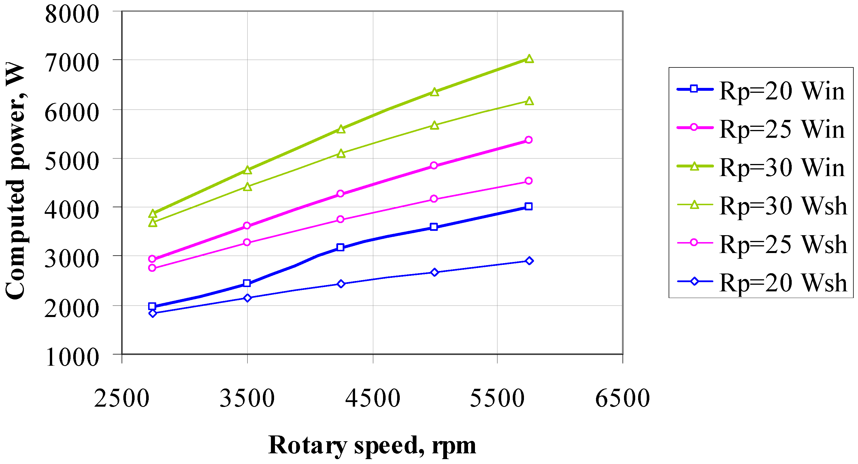
Figure 6 plots the evolution of the expander internal power output and shaft power for given values of pressure ratio and rotary speed. The increase in the expander internal power output when increasing the rotation speed can be clearly observed.
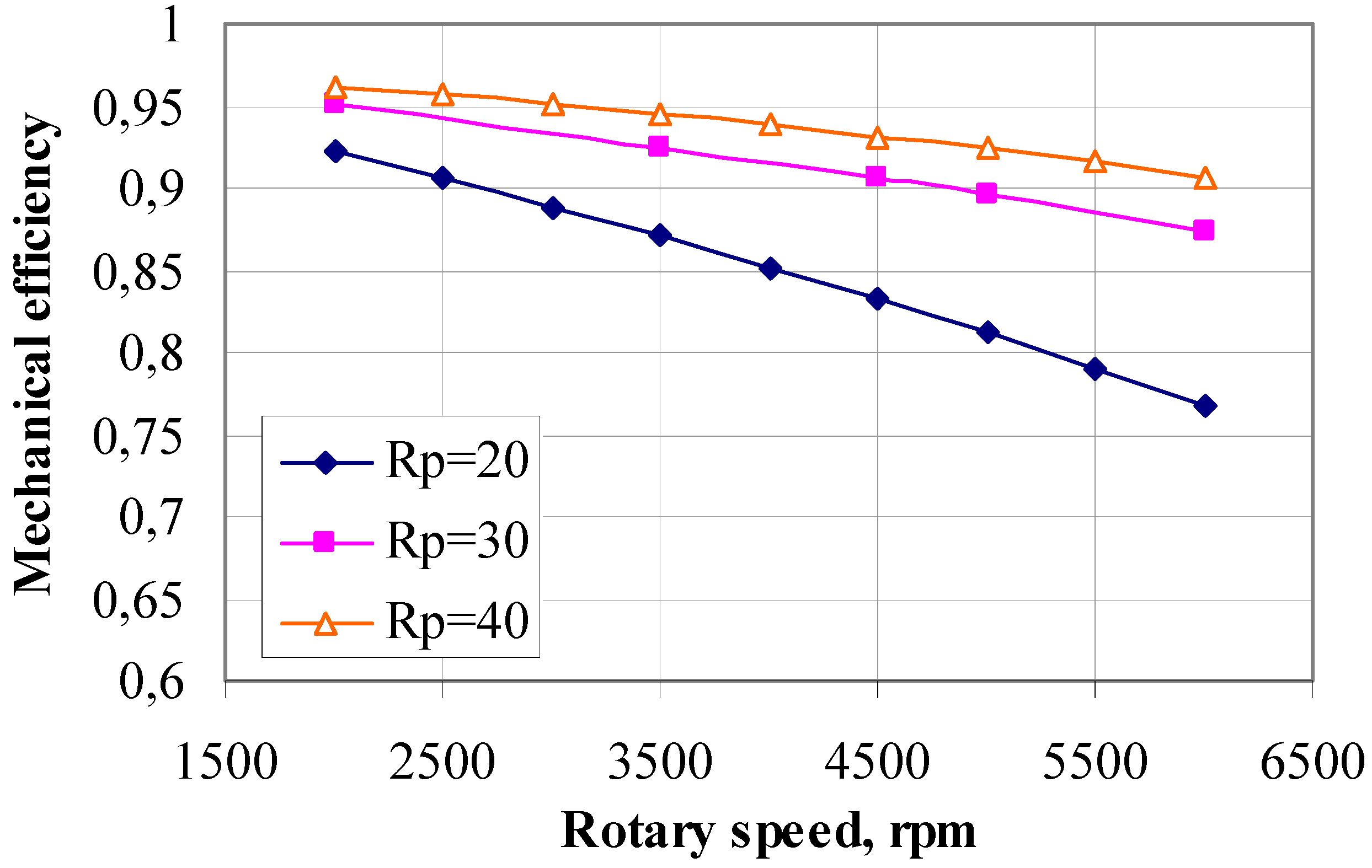
Figure 6 also shows that the higher the pressure ratio, the higher the internal power output. Depending on the operating conditions, an internal power output of 2 to 7 kW can be reached. The shaft power output also increases when the rotary speed and pressure ratio increase. This is due to an increase in the internal power output. Moreover, the difference between internal and shaft power is greater at high values of rotary speed due to mechanical losses. It is obvious that mechanical losses increase when the expander rotary speed increases. The amount of mechanical losses can be expressed by the mechanical efficiency of the expander (
Figure 7). It should be pointed out that the mechanical efficiency decreases with the rotary speed and pressure ratio.
Figure 6.
Evolution of the expander internal power output and shaft power at different pressure ratios and rotary speeds.
Figure 6.
Evolution of the expander internal power output and shaft power at different pressure ratios and rotary speeds.
Figure 7.
Evolution of the mechanical efficiency at different pressure ratios and rotary speeds.
Figure 7.
Evolution of the mechanical efficiency at different pressure ratios and rotary speeds.
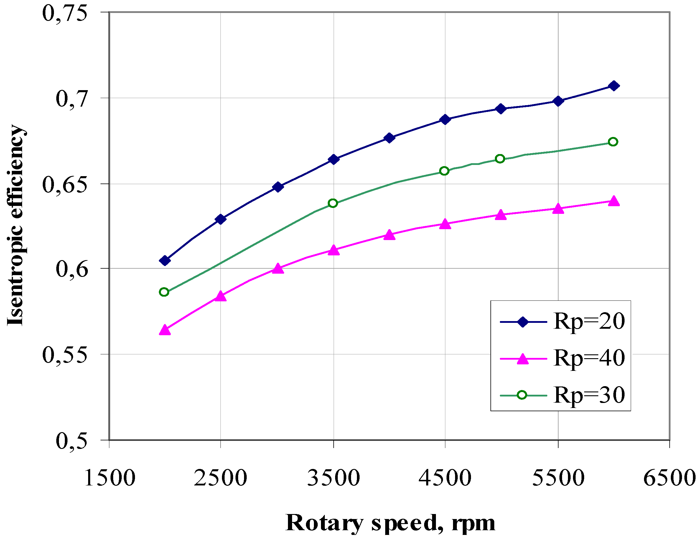
The influence of the pressure ratio and expander rotary speed on the expander efficiency was also analyzed. It can be observed from
Figure 8 that the reciprocating expander is characterized by a relatively high isentropic efficiency of 55 to 70%. The isentropic efficiency increases with the rotary speed. It can be seen from the curves in
Figure 8 that the higher the pressure ratio on the expander, the lower its isentropic efficiency. This can be explained by the power losses due to under expansion of the working fluid.
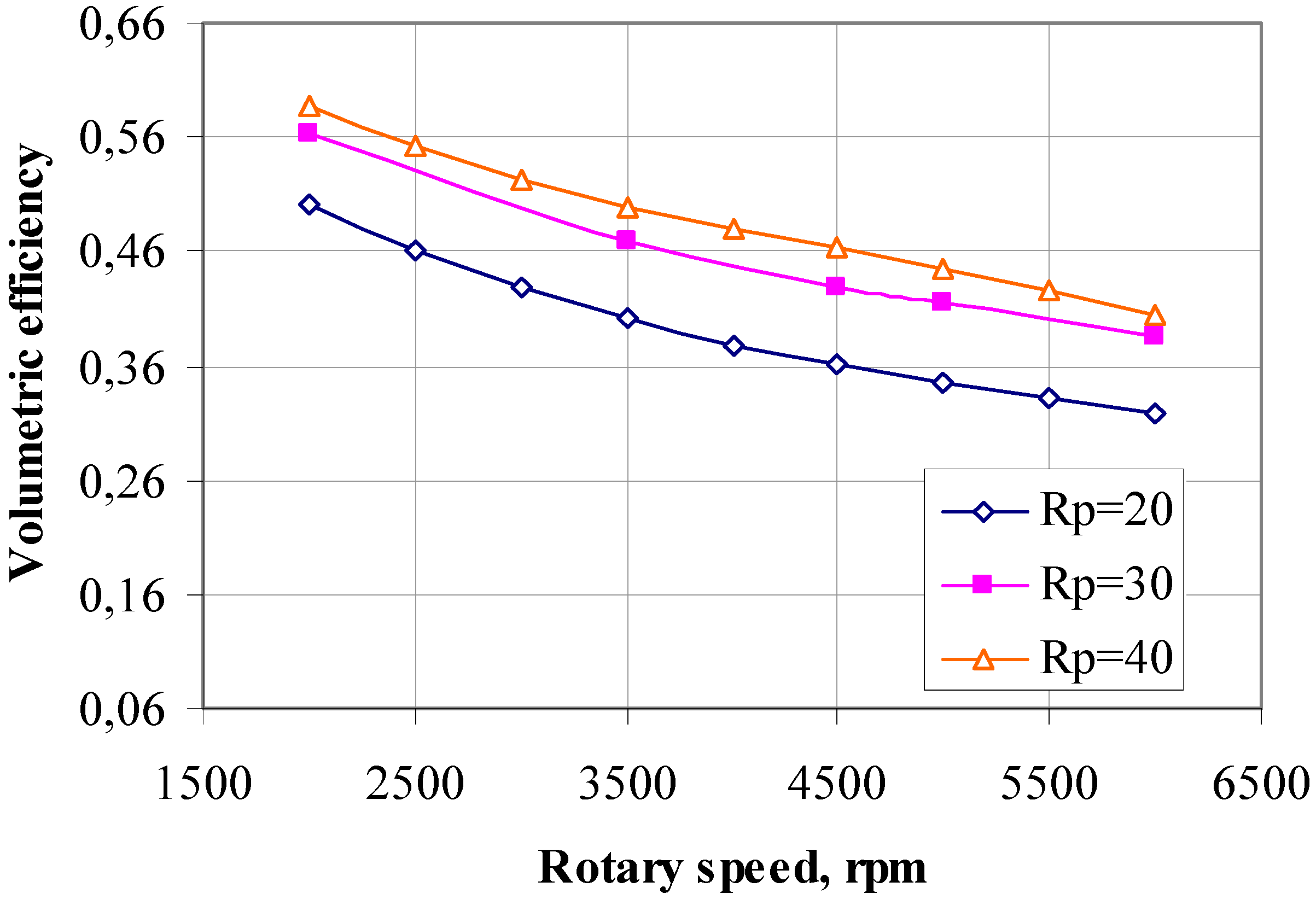
The volumetric efficiency decreases as the expander rotary speed increases (
Figure 9), due to the rapid opening and closing of the supply valve and associated pressure losses. At a constant pressure ratio, the pressure losses increase when the rotary speed increases. This increase in pressure losses influences the volumetric efficiency. It can be seen from
Figure 9 that the volumetric efficiency diminishes as the pressure ratio decreases. This can be explained by an increase in the internal leakages. It should be pointed out that the volumetric efficiency varies from 30 to 60%.
Figure 8.
Evolution of the isentropic efficiency at different pressure ratios for rotary speed.
Figure 8.
Evolution of the isentropic efficiency at different pressure ratios for rotary speed.
Figure 9.
Evolution of the volumetric efficiency at different pressure ratios and rotary speeds.
Figure 9.
Evolution of the volumetric efficiency at different pressure ratios and rotary speeds.
5. Conclusions
Among several technologies for the recovery of the wasted energy of combustion engines, the Rankine cycle system was chosen for examination. In order to optimize the performance of the heat recovery Rankine cycle for an automotive application, the choice of the expander technology is crucial. The survey of the different technologies carried out in this paper led us to the conclusion that a reciprocating machine is an adequate solution for an automotive application.
In order to understand the operation of the piston expander for an automotive waste heat recovery application, a steady-state semi-empirical model was developed. The model was validated using the manufacturer’s expander data. The model accurately predicts the mass flow rate, the power output and the exhaust specific enthalpy of the working fluid. The overall prediction error of the expander performance is 4.7%.
The validated model was used to study the performance of the reciprocating expander. The maximum power output of 7 kW can be reached at a high operating point. The lower the rotary speed and pressure ratio of the expander, the lower the power output. The evolution of the isentropic, mechanical and volumetric efficiencies at different operating conditions was also investigated. This analysis showed that the isentropic efficiency of the reciprocating expander varies from 55 to 70%. The mechanical efficiency depends on the mechanical losses and decreases as the expander rotary speed increases. The volumetric efficiency decreases as the rotary speed increases.
The study of the reciprocating expander showed that this machine could be a promising technology for a waste heat recovery application within a vehicle. In order to study the Rankine cycle performance by means of modeling, the developed expander model can easily be integrated into a Rankine cycle model because of the low computation time.


 —leakage mass flow rate, kg/s.

 —compression work;
  —expansion work;
  —discharge work;
  —admission work.


 , W/K.


 —mass flow rate given by the expander manufacturer, kg/s;
  —mass flow rate calculated by the model, kg/s;
  —internal power output given by the expander manufacturer, W;
  —internal power output calculated by the model, W;
  —exhaust enthalpy of the working fluid given by the expander manufacturer, J/kg;
  —exhaust enthalpy of the working fluid calculated by the model, J/kg.