A Review on Concepts, Applications, and Models of Aquifer Thermal Energy Storage Systems

Department of Environmental and Energy Systems Engineering, Kyonggi University, Suwon, Kyonggi 443-760, Korea
Energies 2010, 3(6), 1320-1334; https://doi.org/10.3390/en3061320
Submission received: 6 May 2010
/
Accepted: 13 June 2010
/
Published: 22 June 2010
(This article belongs to the Special Issue Geothermal Power)
Abstract
:Being a heat source or sink, aquifers have been used to store large quantities of thermal energy to match cooling and heating supply and demand on both a short-term and long-term basis. The current technical, economic, and environmental status of aquifer thermal energy storage (ATES) is promising. General information on the basic operation principles, design, and construction of ATES systems is discussed in this paper. Numerous projects in operation around the world are summarized to illustrate the present status of ATES. Hydrogeological-thermal simulation has become an integral part of predicting ATES system performance. Numerical models which are available to simulate an ATES system by modeling mass and heat transport in the aquifer have been summarized. This paper also presents an example of numerical simulation and thermohydraulic evaluation of a two-well, ATES system operating under a continuous flow regime.
1. Introduction
As the demand for energy increases, effective or enhanced energy conservation is crucial. Around the world, thermal energy storage (TES) system applications have been shown to provide economical and environmentally friendly solutions to energy problems and increasing attention has been paid to their utilization [1,2]. The basic purpose behind thermal storage is to provide a buffer to balance fluctuations in supply and demand of low temperature thermal energy. TES makes it possible to more effectively utilize new renewable energy sources (solar, geothermal, ambient, etc.) and waste heat/cold recovery for space heating and cooling. With a storage medium of various types and sizes, TES systems therefore contribute to improving energy efficiency.
Underground thermal energy storage (UTES) has been used for seasonal storage of large quantities of thermal energy to supply process cooling, space cooling, space heating, and ventilation air preheating [3]. UTES systems are usually divided into two groups. In borehole thermal energy storage (BTES) systems, also called “closed” systems, a fluid (water in most cases) is pumped through heat exchangers in the ground. In aquifer thermal energy storage (ATES) or “open” systems, groundwater is pumped out of the ground and injected into the ground by using wells to carry the thermal energy into and out of an aquifer [4].
Aquifer thermal energy storage systems utilize low-temperature geothermal aquifer resources [5,6]. Being necessary for the implementation of ATES, aquifers are underground, water-yielding geological formations, either unconsolidated or consolidated. Two hydraulically-coupled wells are normally used to separate water supply from storage. Aquifers can be discharged effectively through production wells to meet large cooling and heating demands.
An advantage of open systems is the generally higher heat transfer capacity of a well compared to a borehole. This makes ATES usually the cheapest alternative if the subsurface is hydrogeologically and hydrochemically suited for the system. Such aquifers have potential to offer an economical way of storing thermal energy for long periods of time. ATES systems have been successfully used around the world for the seasonal storage of heat and cold energy for the purpose of heating and/or cooling residential and industrial buildings and greenhouses [7,8,9,10,11].
The present work reviews basic concepts and operation regime of ATES systems. This paper attempts to summarize developments during the last four decades and current statistics on aquifer thermal energy storage around world. The review also covers a general procedure for design and construction of ATES systems. Mathematical theory on the thermo-hydrogeological modeling of ATES systems is discussed. The features of a variety of simulation codes are summarized. Finally, an example of modeling and simulation of hypothetical ATES systems for long-term heat storage operations is presented.
2. Basic Concepts and Applications
Being similar to direct use of a groundwater-geothermal system, aquifer thermal energy storage involves drilling a few wells into an aquifer for circulation of water between the storage region and the energy system. Then it can store energy whilst providing heating and cooling on a seasonal basis. The wells are separated by a critical distance to ensure that the warm and cold storage remain separate and that thermal breakthrough does not occur within one season. This critical distance is primarily a function of operational and thermohydraulic parameters involving the well production rates, the aquifer thickness, and the hydraulic and thermal properties that control the storage volume. A plant can also be made with groups of wells instead of just two wells. Multiple-well configurations have been employed where large volumes of water are required and in systems where individual well yields are low. Single-well applications have also been employed using vertical separation of hot and cold groundwater where multiple aquifers exist.
2.1. Operational Principles
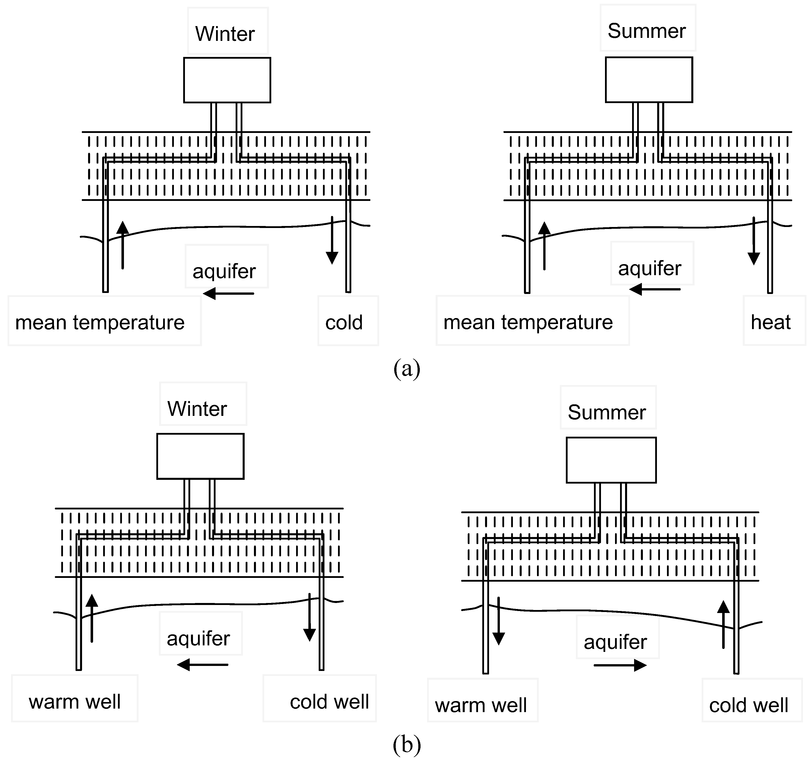
Usually, a pair of wells are pumped constantly in one direction or alternatively, from one well to the other, especially when both heating and cooling being provided. As presented in Figure 1, these two operation principles are called continuous regime and cyclic regime, respectively. The continuous regime only is feasible for plants where the load can be met with temperatures close to natural ground temperatures, and the storage part is more an enhanced recovery of natural ground temperatures. With a continuous flow, design and control of the system are much simpler and easier. Only one well or group of well needs to be equipped with pumps. A disadvantage is the limited temperature range. Cyclic flow will create a definite cold and heat reservoir around each well or group of wells. It is possible to maintain a ground volume above or below the natural ground temperature all the time. One disadvantage is a more complicated well design and control system with each well being able to both produce and inject groundwater.
Figure 1.
Basic operational regimes for aquifer thermal energy storage (a) continuous regime. (b) cyclic regime. (after Nielsen [3].)
Figure 1.
Basic operational regimes for aquifer thermal energy storage (a) continuous regime. (b) cyclic regime. (after Nielsen [3].)

2.2. History and Current Status
The deliberate storage of cold water in an aquifer for later use or ATES has a history of more than forty years. Applications of ATES in large-scale projects started in the 1960s, mostly in China. In 1965, ATES was originated in Shanghai, China where excessive groundwater extraction related to industrial cooling had resulted in significant land subsidence [12]. To rectify the subsidence problem, cold water (from surface waters) was injected into the aquifers. Subsequently, it was observed that the injected and “stored” water had maintained its cool temperature for a long period of time and was suitable for industrial cooling. By 1984, some 492 cold storage wells, supplying cold thermal energy to the industries to cool down the machinery were in use [13].
The development of ATES in North America and Europe focused on the independent storage of cold and heat energy [13]. Environmental impacts related to aquifer warming, as well as the need for both heating and cooling, called for a technology advancement that would allow the effective storage of both warm and cold energy at different times of the year. The first application in Canada of a combined heating and cooling ATES for a new building was at the Scarborough Centre building of the Government of Canada. In many areas, the natural groundwater temperature is suitable for direct cooling. For example, in Winnipeg, Manitoba, the natural groundwater temperature is 6 °C. However, the reinjection of warm waste energy may result in a gradual warming of the aquifer, ultimately leading to aquifer degradation and lower system efficiency for cooling. ATES can avoid the gradual warming of the aquifer by using the waste heat for ventilation air preheating in winter.
Numerous ATES facilities are in operation in Sweden, Germany, The Netherlands, Belgium, and some other European countries. Among the various countries applying ATES systems already, there are significant differences in the number of applications [14]. In Sweden, the number of ATES plants is over 50 and they are used for commercial and institutional buildings from small scale applications to large scale utilization in district heating and cooling [15].
Without being a booming market, more than ten ATES systems are in operation in Belgium at the end of 2005. All large scale (>500 kW) and most of them are located in the Campine due to the hydrogeological conditions [16]. Recently, there is a growing interest in the application of ATES for the heating and cooling of buildings in Denmark [14]. The first project of this kind was operational by the end of 2007. Only a few ATES projects have been installed in Germany [14].
The Netherlands are probably the technological leaders in the field. Given the good experience with aquifer storage in later projects and the fact that in the Netherlands aquifers can be found almost everywhere, in particular the application of ATES has been further developed in the Netherlands. In 2005, the number of registered ATES projects was 537. About 80% of the applications are in the commercial building sector (office blocks, hospitals and shopping centers) and the rest is for industrial and agricultural cooling. The potential contribution of cold storage to energy production in the Netherlands by 2020 is estimated to be 15 PJ. This corresponds to 500 million m3 of natural gas [17].
There is only one known ATES system installed to date in the UK [14]. Installed in 2006, the system is for a residential development in West London and has a storage capacity of 250 kW. By the end of 2007, there were a number of larger scale ATES and BTES systems under development, and the level of interest in UTES application is increasing.
More recently, the increasing use of groundwater source heat pumps for heating and cooling has stimulated ATES applications with heat pump. A groundwater source heat pump connected to a cold well and a warm well is rudimentary ATES system.
Experiences have revealed that a significant number of ATES plants have had or have operational and maintenance problems or failures [12]. The dominating reasons behind these problems are chemical changes in groundwater caused by the temperature and pressure variations associated with ATES. Examples are clogging of aquifer, mineral precipitation in well screens, and corrosion, etc. The major part of these has been solved by fairly simple measures such as proper design, materials selection and operation.
3. Design and Construction
Any ATES realization is a quite complex procedure and has to follow a certain pattern to be properly developed. Andersson [18] provided a general procedure for design and construction of ATES system.
3.1. Design Procedure
Typical design steps are as follows:
- (1)
- pre feasibility studies to describe the principal issues,
- (2)
- feasibility study to tell the technical and economical feasibility and environmental impact compared to more than one reference systems,
- (3)
- the first permit applications to local authorities,
- (4)
- definition of hydrogeological conditions by site investigations and measurements of loads and temperatures, etc on the user side,
- (5)
- evaluation of results and modeling for technical, legal, and environmental purposes,
- (6)
- final design for tender documents,
- (7)
- final permit application for court procedures.
Though the technical issues are general, the permitting procedure may vary from country to country. However, in most countries the use of ground water for energy purposes will be restricted and will be an issue for application according to different kind of actions.
3.2. Field Investigation
One essential part in developing an ATES project is to perform site investigations. The more knowledge that is obtained of the aquifer properties, the better basis for design is achieved. Some important parameters for an ATES installation are high ground porosity, medium to high hydraulic transmission rate around the boreholes, but a minimum of ground water flow through the reservoir. Ground water chemistry represents another set of parameters that must be given proper attention in order to prevent scale formation. The site investigations most commonly cover the following procedures [17]:
- (1)
- geological mapping
- (2)
- geophysical investigations
- (3)
- test drillings
- (4)
- pumping tests
The test drillings will define the stratigraphic units in the area while the geophysical investigation and geological mapping are used for extrapolation of the layers and for definition of geometry. Test drillings may be a part of the final system and can be considered as an early investment in the system. More commonly they do not fit into the final system after design because they are drilled with small dimensions. In these cases, they can still be used as observation wells. For shallow aquifers in the overburden it is common to drive slim steel pipes that are perforated in the lower meter or so. This method has proven to be an excellent way of taking samples for the design of screened production wells.
Based on the results of field investigation, a conceptual model is created and the hydraulic properties of the aquifer and its surrounding layers are derived. The final outcome will be a geological model that is more or less accurate and that can be used for the final design using simulation models. To be able to make model simulations, the loading conditions of heat and cold should be known. It is common to perform measurements on how the loads are varied at different outdoor temperatures. Such investigations that also covers supply and return temperatures in the distribution systems are often done prior to or in parallel with the underground site investigations. The results are key factors as basis for design in order to calculate flow rates and size of the ATES storage.
4. Numerical Simulations
An understanding of the thermohydraulic processes in the aquifer is essential for the proper design of an aquifer heat storage system under given conditions. The main design consideration includes the location of wells, the loading conditions (injection rate and temperature), heat losses, and thermal breakthrough time. It is also necessary to assess the consequences of uncertainties associated with the storage in underground regions without detailed investigation [19].
At present, the use of computer modeling constitutes an integral part of the prediction and evaluation of system performance in the geothermal setting [20,21]. To optimize ATES design and development, a numerical modeling based on coupled mass and energy transport theory has to be conducted to evaluate the behavior of the local subsurface geothermal system.
A number of researchers have highlighted the role of numerical modeling in the analysis of ATES systems. Molson et al. [22] used a three-dimensional finite element model to simulate groundwater flow and energy transport in an unconfined aquifer. Probert et al. [7] presented a thermodynamic evaluation of ATES projects, and listed key aquifer properties and design parameters. Based on an elementary ATES model, Rosen [23] applied second-law analysis to assess the performance of thermal energy storage systems. Chavalier and Banton [24] used the random walk resolution method to a single injection well to study the energy transfer phenomena in ATES. Tenma et al. [25] and Lee and Jeong [26] conducted two-well studies to model the underground design of TES systems. Recent simulation studies for ATES systems consider the effects of regional groundwater flow on heat transfer [27,28].
4.1. Mathematical Theory
To calculate aquifer temperatures at different locations, theoretical principles of water flow and heat transfer phenomena were applied. The coupled groundwater and heat flow are governed by the partial differential equations describing mass and energy balance in the aquifer.
The continuity of mass for water in association with Darcy’s law is expressed as:
where n is porosity [dimensionless], is density of water [ML−3], u is Darcy flux [Lt−1], t is time [t], and is source term [ML−3t−1].
The water flux is related to the gradient of pressure and gravity force through Darcy’s law:
where k is the permeability tensor; the dynamic viscosity [ML−1t−1]; p the pressure [ML−1t−2]; z the vertical depth [L], and the specific gravity (=) [ML−2t−2].
The energy balance equation is derived by assuming energy is only a function of temperature, and energy flux in the aquifer occurs only by convection and conduction. Consequently, the resulting general heat balance equation describing non-isothermal groundwater flow in a saturated porous medium can be formulated as follows:
where T is aquifer temperature [T], and are rock and water heat capacity at constant volume [ML−1t−2T−1], is thermal conductivity of the aquifer [MLt−3T−1], is enthalpy source per unit bulk volume [ML−2t−2], and is heat exchange for overburden and underburden formations [ML−2t−2]. The thermal dependence of density, viscosity, thermal conductivity, and heat capacity is not taken into consideration, as these parameters do not greatly vary in the temperature range considered in an ATES study.
The heat transfer through over- and underlying low-permeability layers is assumed to be due solely due to thermal diffusion. The heat equation is simplified to:
where is the thermal conductivity of overburden or underburden rock [MLt−3T−1]. The heat transfer equation (3), which results from the principle of energy conservation, is coupled with the flow equation from Darcy’s law (2) and the continuity equation (1).
4.2. Simulation Models
Groundwater flow and thermal energy transport in the porous media have been studied in detail in the discipline of hydrogeology. Numerical research into groundwater and heat transport has been continuing for more than a decade in North American and Europe. Numerous commercially available and public domain numerical software codes exist. Of these, focus is given to the simulation modeling both mass and heat transport in groundwater.

| Model | Creator | Numerical Scheme | Description |
|---|---|---|---|
| AQUA3D | Vatnaskil Consulting Engineers, Reykjavik, Iceland | finite-element method | developed mainly for simulation of mass transport problems, but can be adapted to model heat transport without density-dependent groundwater flow |
| HST3D | United States Geological Survey (USGS) | finite-difference method | capable of simulating mass and heat transport in variable-density groundwater flow system |
| FEFLOW | DHI-WASY GmbH, Berlin, Germany | finite-element method | capable of simulating both mass and heat transport in density-dependent groundwater flow systems |
| SUTRA-MS | United States Geological Survey (USGS) | hybrid finite-element and finite-difference method | simulated fluid movement and the transport of either energy or dissolved substances in the subsurface environment |
| THETA 3.0 | Nuclear Engineering Laboratory, Helsinki University of Technology, Finland | finite-difference method | coupled transport of fluid and energy in porous media |
| TOUGH2 | Earth Sciences Division, Lawrence Berkeley National Laboratory | integral finite difference method | simulating the coupled transport of water, vapor, non-condensable gas, and heat in porous and fractured media |
| SHEMAT | Applied Geophysics and Geothermal Energy E.ON Energy Research Center, RWTH Aachen University | finite difference method | simulating coupled flow, heat transfer, transport and chemical water-rock interaction in hydro-geothermal reservoirs in two and three dimensions |
| UTCHEM | Center for Petroleum and Geosystems Engineering, Austin, Texas, U.S.A. | finite difference method | developed mainly for modeling multiphase, multicomponent, compositional simulation of chemical flooding processes, but can be used to model heat transport |
Many simulation codes available to simulate ATES systems have their own merit. Table 1 gives a summary of available numerical models for groundwater flow and energy or solute transport in groundwater [29,30]. These models can all be used to simulate an ATES system. Reviewing numerical software codes, which can be used to model mass and/or heat transport in groundwater, Chiasson [31] suggested the following selection criterion for the model.
- (1)
- the type of boundary conditions handled by the code
- (2)
- the solution scheme employed by the code
- (3)
- verification of the code
- (4)
- cost
4.3. Simulation Example
Amongst the more sophisticated simulators, a general simulator named UTCHEM has proved to be particularly useful for modeling multiphase transport processes under non-isothermal conditions [32]. UTCHEM has been verified by comparing its ability to predict the flow of fluids through the aquifer to analytical solutions and experimental measurements.
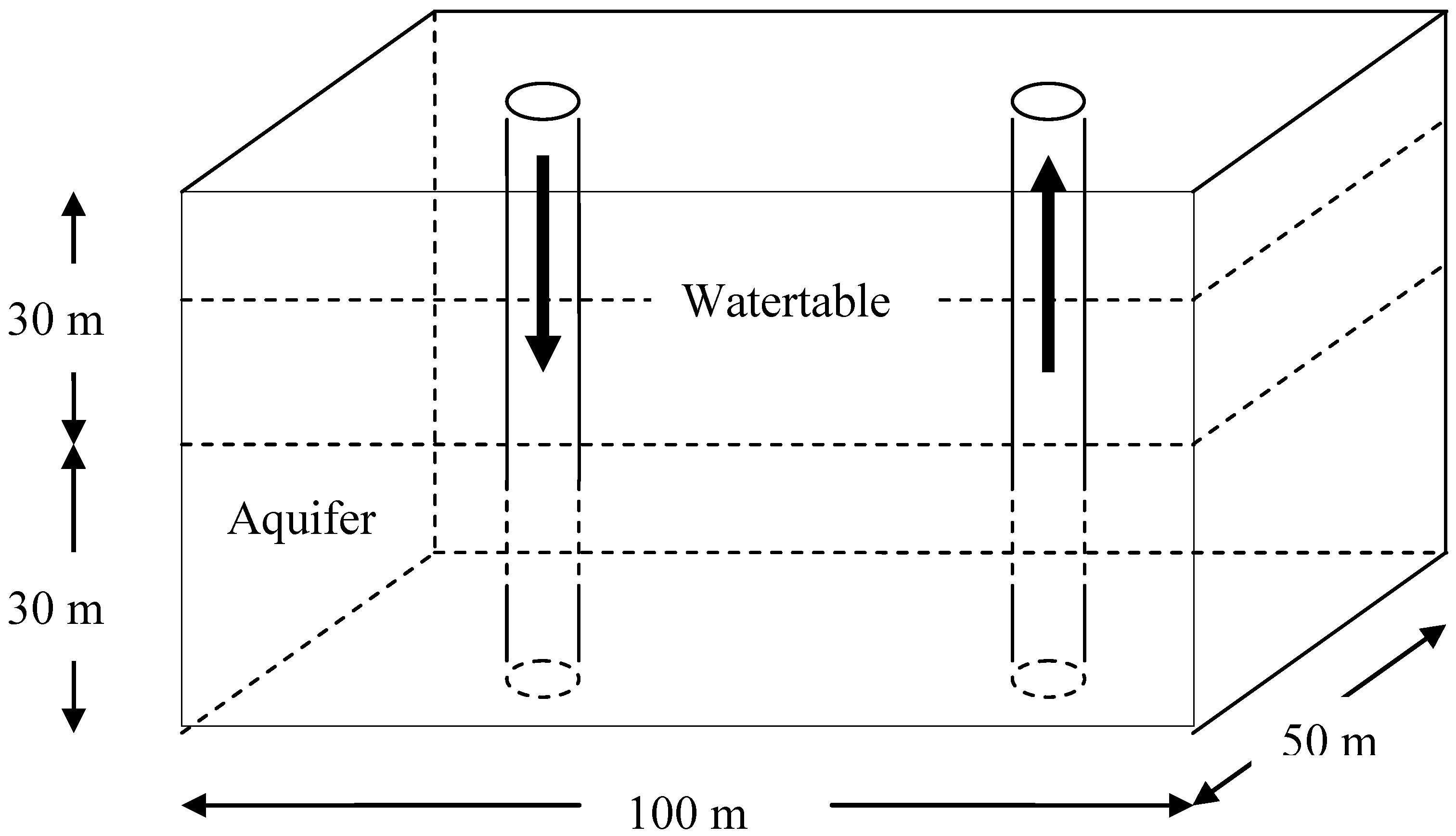
In order to estimate the parameters of an underground system, a general ATES was considered using a two-well open system (Figure 2). Two wells are situated at the center of a 2 ° 1 rectangular field. In the simulation, water was pumped into the injection well at a constant flow rate Q and temperature with the same flow rate of water recovered from the neighboring production well. In a large reservoir with repeated patterns, the flow is symmetrical around each pair of injection-injection wells. Constant pressure was applied to the left and right boundaries to induce regional groundwater flow in response to hydraulic gradient, whilst other boundaries are closed to flow. Outer boundaries are represented as adiabatic in order to simulate symmetry in an array. Heat transfer in the ATES was coupled with heat conduction and advection by the combined flow of injection water and regional groundwater. The geometry of the model is similar to that of a two-well model proposed by Tenma et al. [25].
Figure 2.
Schematic representation of simulation domain.
To assess the character of the system, the two-well model was run for continuous flow regime. Heat transfer within the aquifer was simulated by specifying constant temperature at the injection well, with the aquifer temperature initialized at . The initial temperature of the aquifer was assumed to be constant 17.5 °C through the entire aquifer and confining layers. The pressure difference between left () and right () boundaries ranged from −40 kPa to 40 kPa, with a derived regional ground flow from left to right for or right to left for . The model was run for 10 years to provide an adequate long-term assessment of thermal storage in the system.
The ATES was operated under a continuous flow regime, where water was pumped from one well (equipped with a pump) and injected via a second well. A complete energy storage cycle was composed of four periods per year to simulate the seasonal conditions. Each cycle is symmetrical for identical injection (Q > 0) and production (Q < 0) rates and duration. The thermal field and the temperature of produced water were calculated from the numerical solutions of Equation (3), at constant time interval.
Based on inferred seasonal changes in surface temperatures, injected water temperatures of 5 °C, 15 °C, 25 °C, and 15 °C were assigned for three-month periods through the model simulation. The size of the modeled two-well system is 100 m ° 50 m ° 30 m. The rates of injection (or production) of 100 m3/day correspond to 0.2688 pore volume of the aquifer, for three months.
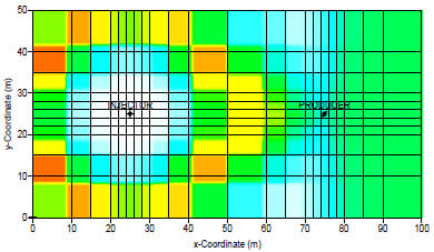
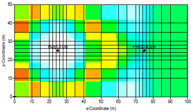
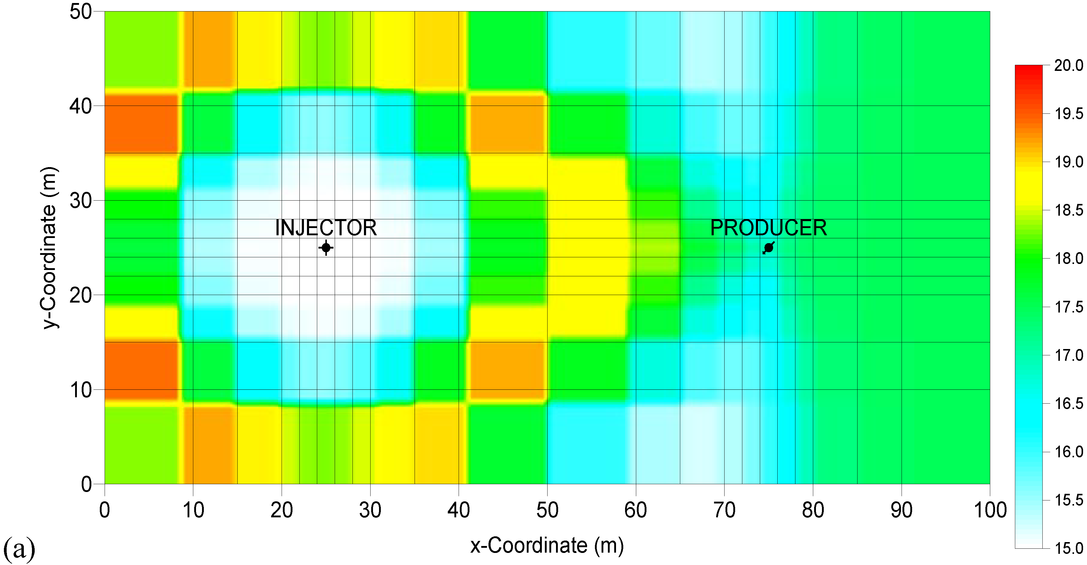
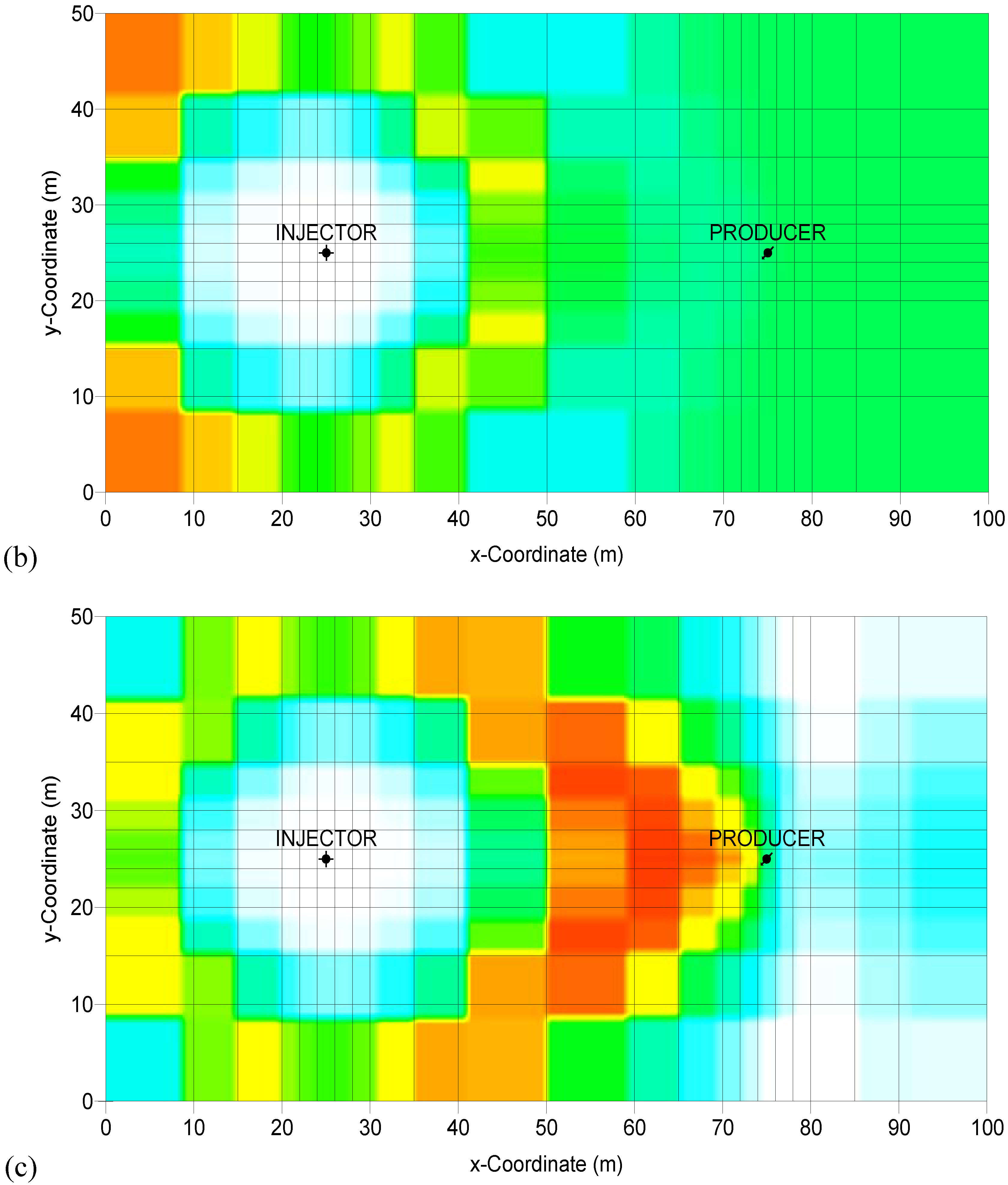
Figure 3(a–c) shows temperature distributions for numerical calculations under boundary conditions of = 0 (no regional groundwater flow), −40 (regional groundwater flow from right to left), and 40 kPa (regional groundwater flow from right to left), after 90 days of cold water injection. From the figures, there is clear evidence for groundwater flow, and influence on the thermal regime. When the direction of regional groundwater flow is same with that of the injected water, increased thermal convection moves the thermal front closer to the producing well.
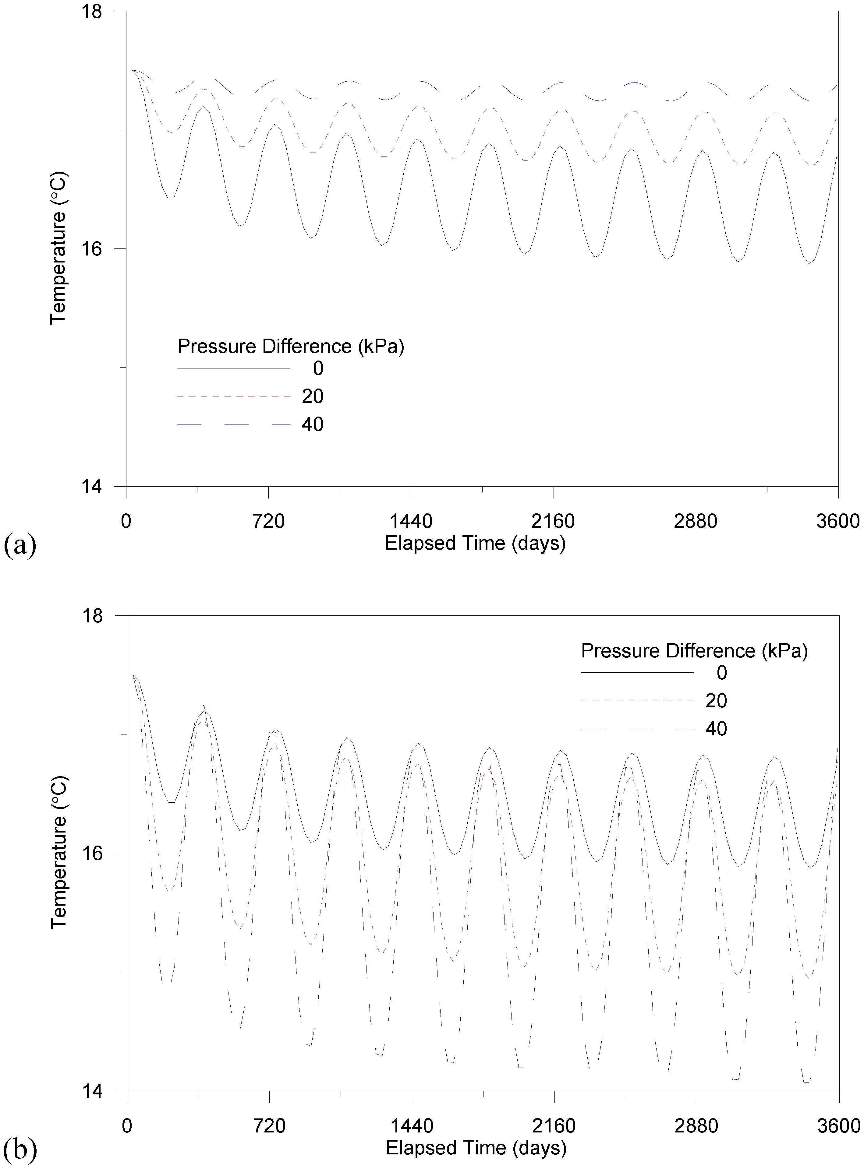
Simulation studies on heat transfer in ATES have been carried out in the absence and presence of a regional groundwater flow. The calculated temperatures of the produced water are shown in Figure 4. A small variation is most desirable, as it points to sustainable use of the aquifer in the TES system. As shown in the figure, temperature decreases in all scenarios. Whilst the temperature of the circulated fluid changes by 25–5 °C, the average temperature of the produced water eventually trends to ~15 °C, which approximates the temperature of the injected water. Due to the energy imbalance between the initial aquifer temperature (17.5 °C) and average injection temperature (15 °C), the aquifer will gradually cool. If the pressure difference is large, then the cooling process is more rapid.
Figure 3.
Temperature distribution [°C] obtained with different groundwater flow after cold water injection. (a) no groundwater flow. (b) groundwater flow from right to left ( = −40 kPa). (c) groundwater flow from left to right ( = 40 kPa).
Figure 3.
Temperature distribution [°C] obtained with different groundwater flow after cold water injection. (a) no groundwater flow. (b) groundwater flow from right to left ( = −40 kPa). (c) groundwater flow from left to right ( = 40 kPa).


The temperature of recovered water fluctuates with a quarterly year period, reflecting the change in temperature of the injected water. The temperature of water at the producing well occurs within the range of 0.94 °C to 2.60 °C for the case of (left to right groundwater flow) and 0.16 °C to 0.94 °C for the case of (right to left groundwater flow) through the ten-year period. Temperature variation can be significant, depending on the pressure difference in the aquifer, as shown in Figure 3. The range of variation for kPa is 16 times greater than that for kPa. As the net change of thermal energy is small, the groundwater flow conditions are more promising under large pressure gradient in an opposite flow direction to the injected water.
Figure 4.
Temperature of produced water obtained from simulations with different groundwater flow condition. (a) groundwater flow from right to left. (b) groundwater flow from left to right.
Figure 4.
Temperature of produced water obtained from simulations with different groundwater flow condition. (a) groundwater flow from right to left. (b) groundwater flow from left to right.

Results of this study clearly reveal that the thermal behavior of the storage system depends on the direction and velocity of the groundwater flow, which is determined by the regional pressure gradient. A flow system opposite to the direction of regional groundwater flow has positive attributes for an effective ATES, because of the small loss and little fluctuation in the extracted thermal energy. Numerical simulations have shown that the thermal front will more closely approach the producing well when the direction of regional groundwater flow is same as that of the injected water, due to increased thermal convection, and will result in a large variation in the temperature of the recovered water. Variations in temperature of the recovered water are inferred to depend on pressure differences in the ATES aquifer-groundwater system.
5. Conclusions
Aquifer thermal energy storage (ATES) systems use natural water in a saturated and permeable underground layer as the storage medium. The transfer of thermal energy is carried out by extracting groundwater from the aquifer and by reinjecting it at a modified temperature into a separate well nearby. In the present work, a brief review is presented on the concepts and applications of ATES systems.
Storage in aquifers has a quite long history and has achieved broad acceptance for heating and cooling in the energy market in many countries, though the application of ATES is quite different among the various countries. High efficiency and the environmental benefits from large savings of fossil fuel and electricity, combined with substantial profit expectations are in favor for a further growth on the market, especially for large-scale applications. Any ATES project involves a quite complex procedure and has to follow a general procedure for design and construction of ATES system
Numerical calculations were carried out to estimate the long-time thermal behavior of a two well, ATES system with under continuous operation methods. The simulated effect of various geometrical and operational parameters on aquifer thermal behavior and final producing temperature, under regional groundwater flow conditions, were studied for a 10-year, continuous injection and withdrawal system. The thermal behavior of the storage system depends on the direction and velocity of the groundwater flow, which is determined by regional pressure gradient. The hypothetical scenarios tested for the two-well ATES system in this study show hydrogeological-thermal simulation to be a valuable tool in assessing the sensitivity of various hydrological parameters in ATES, and an integral part of predicting system performance.
References
- Paksoy, H.O.; Gurbuz, Z.; Turgut, B.; Dikici, D.; Evliya, H. Aquifer thermal storage (ATES) for air-conditioning of supermarket in Turkey. Renew. Energy 2004, 29, 1991–1996. [Google Scholar] [CrossRef]
- Dincer, I.; Rosen, M.A. Energetic, exergetic, environmental and sustainability aspects of thermal energy storage systems. In Thermal Energy Storage for Sustainable Energy Consumption; Paksoy, H.O., Ed.; Springer: Dordrecht, The Netherlands, 2007; pp. 23–46. [Google Scholar]
- Nielsen, K. Thermal Energy Storage, A State-of-the-Art; NTNU: Trondheim, Norway, 2003. [Google Scholar]
- Novo, A.V.; Bayon, J.R.; Castro-Fresno, D.; Rodriguez-Hernandez, J. Review of seasonal heat storage in large basins: Water tanks and gravel-water pits. Appl. Energy 2010, 87, 390–397. [Google Scholar] [CrossRef]
- Sanner, B. Shallow geothermal energy. GHC Bullet. 2001, 22, 19–25. [Google Scholar]
- Rafferty, K. Ground water issues in geothermal heat pump systems. Groundwater 2003, 41, 408–410. [Google Scholar] [CrossRef]
- Probert, T.; Hellsröm, G.; Claesson, J. Thermohydraulic evaluation of two ATES projects in southern Sweden. In Proceedings of International Symposium on Aquifer Thermal Energy Storage, Tuscaloosa, AL, USA, 14–15 November 1994; pp. 73–81.
- Paksoy, H.O.; Andersson, O.; Abaci, H.; Evliya, H.; Turgut, B. Heating and cooling of a hospital using solar energy coupled with seasonal thermal energy storage in aquifer. Renew. Energy 2000, 19, 177–122. [Google Scholar] [CrossRef]
- Allen, D.M.; Ghomshei, M.M.; Sadler-Brown, T.L.; Dakin, A.; Holtz, D. The current status of geothermal exploration and development in Canada. In Proceedings of World Geothermal Congress 2000, Kyushu-Tohoku, Japan, 28 May–10 June 2000; pp. 55–58.
- Schmidt, T.; Mangold, D.; Muller-Steinhagen, H. Seasonal thermal energy storage in Germany. In Proceedings of ISES Solar World Congress 2003, Göteborg, Schweden, 14–19 June 2003; pp. 1–7.
- Courtois, N.; Grisey, A.; Grasselly, D.; Menjoz, A.; Noel, Y.; Petit, V.; Thiery, D. Application of aquifer thermal energy storage for heating and cooling of greenhouses in France: A pre-feasibility study. In Proceedings of European Geothermal Congress 2007, Unterhaching, Germany, 30 May–1 June 2007; pp. 1–8.
- Morofsky, E.L. ATES-energy efficiency, economics, and the environment. In Proceedings of International Symposium on Aquifer Thermal Energy Storage, Tuscaloosa, Alabama, USA, 14–15 November 1994; pp. 1–8.
- Gao, Q.; Li, M.; Yu, M.; Spitler, J.D.; Yan, Y.Y. Review of development from GSHP to UTES in China and other countries. Renew. Sustain. Energy Rev. 2009, 13, 1383–1394. [Google Scholar] [CrossRef]
- Hendriks, M.; Snijdersl, A.; Boid, N. Underground thermal energy storage for efficient heating and cooling of buildings. In I3CON Conference, Loughborough, UK, 14–16 May 2008.
- Andersson, O.; Hellström, G.; Nordell, B. Heating and cooling with UTES in Sweden—Current situation and potential market development. In Proceedings of the 9th International Conference on Thermal Energy Storage, Warsaw, Poland, 1–4 September 2003; pp. 359–366.
- Desmedt, J.; Hoes, H.; Van Bael, J. Status of underground thermal energy storage in Belgium. In 2006 Ecostock Conference, Pomona, NJ, USA, 31 May–2 June 2006.
- Paksoy, H. Underground Thermal Energy Storage—A Choice for Sustainable Future. World Energy Council Publications. Available online: htttp://www.worldenergy.org/wec-geis/publications (accessed on 9 June 2010).
- Andersson, O. Aquifer thermal energy storage. In Thermal Energy Storage for Sustainable Energy Consumption; Paksoy, H.O., Ed.; Springer: Dordrecht, The Netherlands, 2007; pp. 155–176. [Google Scholar]
- Claesson, J.; Hellström, G.; Probert, T. Simulation models for ATES. In Proceedings of International Symposium on Aquifer Thermal Energy Storage, Tuscaloosa, AL, USA, 14–15 November 1994; pp. 131–137.
- Breger, D.B.; Hubbell, J.E.; Hasnaoui, H.E.; Sunderland, J.E. Thermal energy storage in the ground: Comparative analysis of heat transfer modeling using U-tubes and boreholes. Solar Energy 1996, 56, 493–503. [Google Scholar] [CrossRef]
- O’Sullivan, M.J.; Pruess, K.; Lippmann, M.J. State of the art of geothermal reservoir simulation. Geothermics 2001, 30, 395–429. [Google Scholar] [CrossRef]
- Molson, J.W.; Frind, E.O.; Palmer, C.D. Thermal energy storage in an unconfined aquifer. 2. Model development, validation, and application. Water Resour. Res. 1992, 28, 2857–2867. [Google Scholar] [CrossRef]
- Rosen, M.A. Second-law analysis of aquifer thermal energy storage systems. Energy 1999, 24, 167–182. [Google Scholar] [CrossRef]
- Chavalier, S.; Banton, B. Modelling of heat transfer with the random walk method. Part 1. Application to thermal storage in porous aquifers. J. Hydr. 1999, 222, 129–139. [Google Scholar] [CrossRef]
- Tenma, N.; Yasukawa, K.; Zyvoloski, G. Model study of thermal storage system by FEHM code. Geothermics 2003, 32, 603–607. [Google Scholar] [CrossRef]
- Lee, K.S.; Jeong, S.J. Numerical modeling on the performance of aquifer thermal energy storage system under cyclic flow regime. Int. J. Green Energy 2008, 5, 1–14. [Google Scholar] [CrossRef]
- Nagano, K.; Mochida, T.; Ochifuji, K. Influence of natural convection on forced horizontal flow in saturated porous media for aquifer thermal energy storage. Appl. Thermal Eng. 2002, 22, 1299–1311. [Google Scholar] [CrossRef]
- Fan, R.; Jiang, Y.; Yao, Y.; Shiming, D.; Ma, Z. A study on the performance of geothermal heat exchanger under coupled heat conduction and groundwater advection. Energy 2007, 32, 2199–2209. [Google Scholar] [CrossRef]
- Deng, Z. Modeling of Standing Column Wells in Ground Source Heat Pump Systems. Ph.D. dissertation, Oklahoma State University, Stillwater, OK, USA, 2004. [Google Scholar]
- Schmidt, T.; Hellström, G. Ground Source Cooling—Working Paper on Usable Tools and Methods; COWI A/S: Kongens Lyngby, Denmark, 2005. [Google Scholar]
- Chiasson, A. Advances in Modeling of Ground-Source Heat Pump Systems. Master’s thesis, Oklahoma State University, Stillwater, OK, USA, 1999. [Google Scholar]
- Center for Petroleum and Geosystems Engineering. UTCHEM-9.0 A Three-Dimensional Chemical Flood Simulator; Uiversity of Texas at Austin: Austin, TX, USA, 2000. [Google Scholar]
© 2010 by the authors; licensee MDPI, Basel, Switzerland. This article is an Open Access article distributed under the terms and conditions of the Creative Commons Attribution license (http://creativecommons.org/licenses/by/3.0/).
Share and Cite
MDPI and ACS Style
Lee, K.S. A Review on Concepts, Applications, and Models of Aquifer Thermal Energy Storage Systems. Energies 2010, 3, 1320-1334. https://doi.org/10.3390/en3061320
AMA Style
Lee KS. A Review on Concepts, Applications, and Models of Aquifer Thermal Energy Storage Systems. Energies. 2010; 3(6):1320-1334. https://doi.org/10.3390/en3061320
Chicago/Turabian StyleLee, Kun Sang. 2010. "A Review on Concepts, Applications, and Models of Aquifer Thermal Energy Storage Systems" Energies 3, no. 6: 1320-1334. https://doi.org/10.3390/en3061320