The DFIG wind turbine configuration, which nowadays represents the mainstream configuration for large wind turbines [
6], is illustrated in
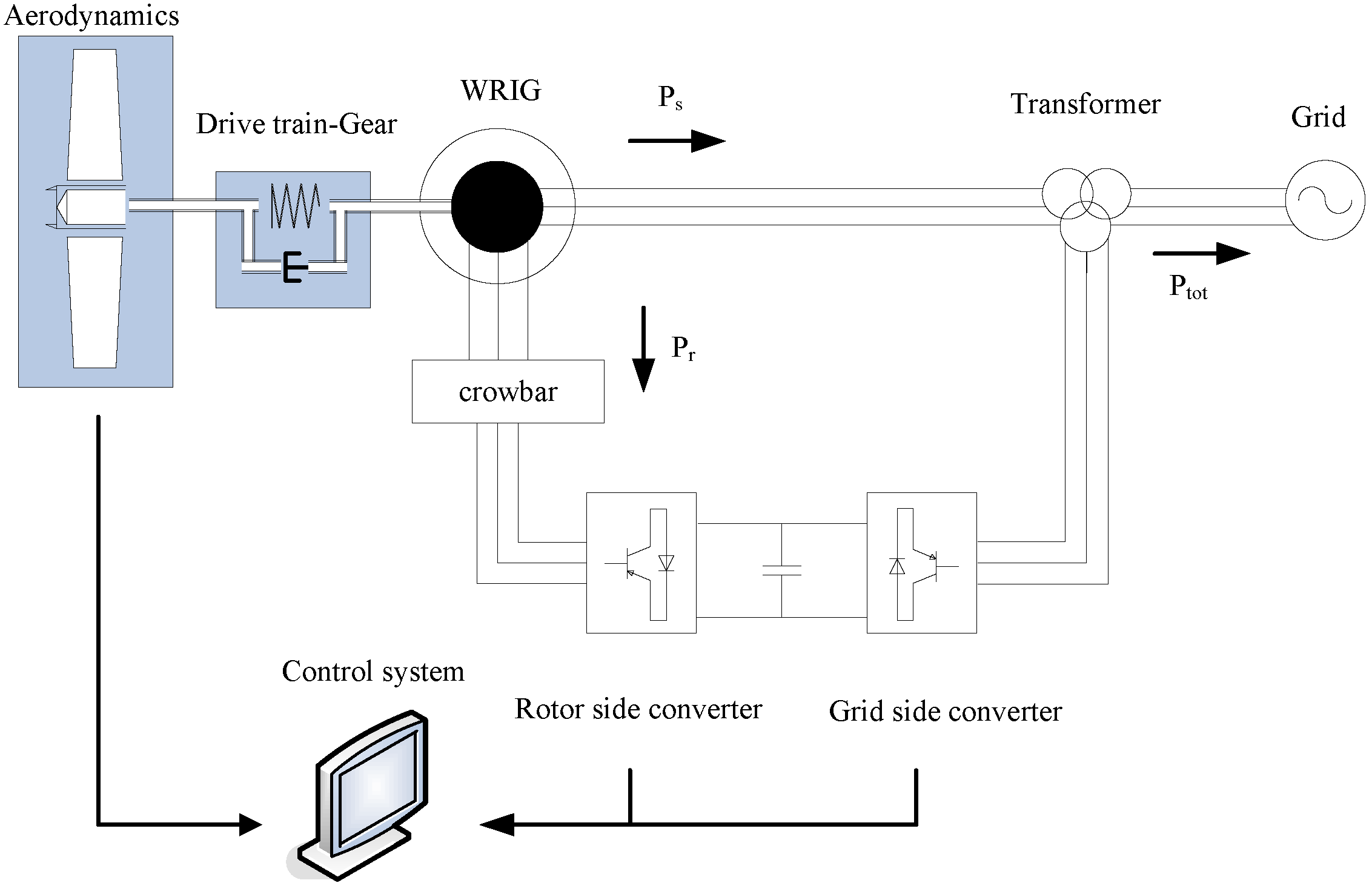
Figure 1. The main electrical components, as well as the mechanical parts and the controllers, have to be considered in the model in order to ensure a realistic response. As the model used in this study for the DFIG wind turbine configuration is described in detail in [
7], only a brief summary is presented in the following.
Figure 1.
System configuration of a DFIG wind turbine.
The DFIG system is essentially a wound rotor induction generator with slip rings, with the stator directly connected to the grid and with the rotor interfaced through a back-to-back partial-scale power converter [
8]. The converter consists of two conventional voltage source converters (rotor-side converter RSC and grid-side converter GSC) and a DC-bus.
A two-mass model is usually used to represent the drive train to illustrate the dynamic impact of wind turbines on the grid properly. A large mass for the wind turbine rotor and a small mass for the generator are thus connected by a flexible shaft characterized by stiffness and damping for the low-speed shaft. A simplified aerodynamic model, based on a two-dimensional aerodynamic torque coefficient
Cq table [
8], is typically sufficient for such studies.
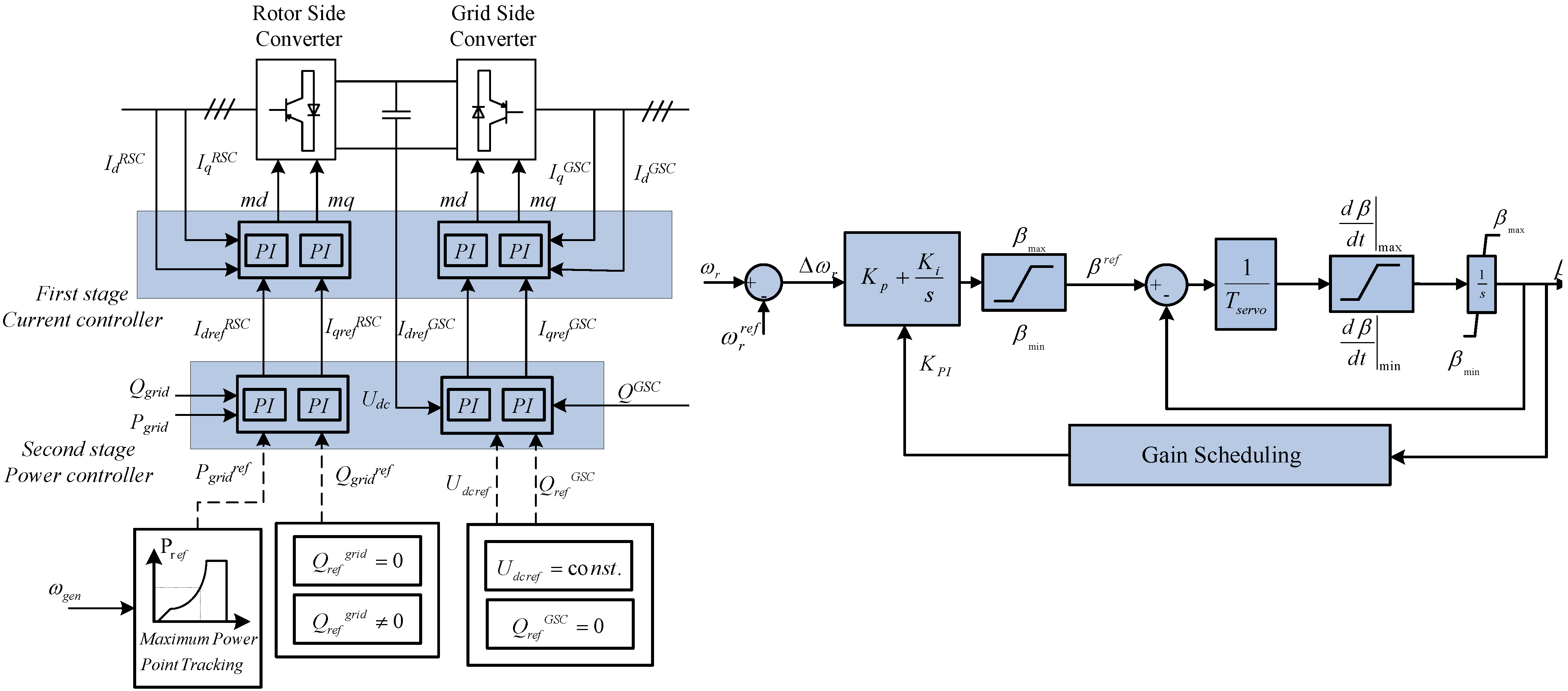
The control system consists of a pitch controller and an electrical control for the converters. The pitch control system is realized by a PI controller with antiwind-up, using a servomechanism model with limitation of both the pitch angle and its rate of change. As the pitch angle directly controls the generator speed to its reference signal, this control is able to prevent over-speeding both in normal operations and during grid faults, by limiting the mechanical power extracted from the wind and thus restoring the balance between electrical and mechanical power.
2.1. Power production regulation during normal operation
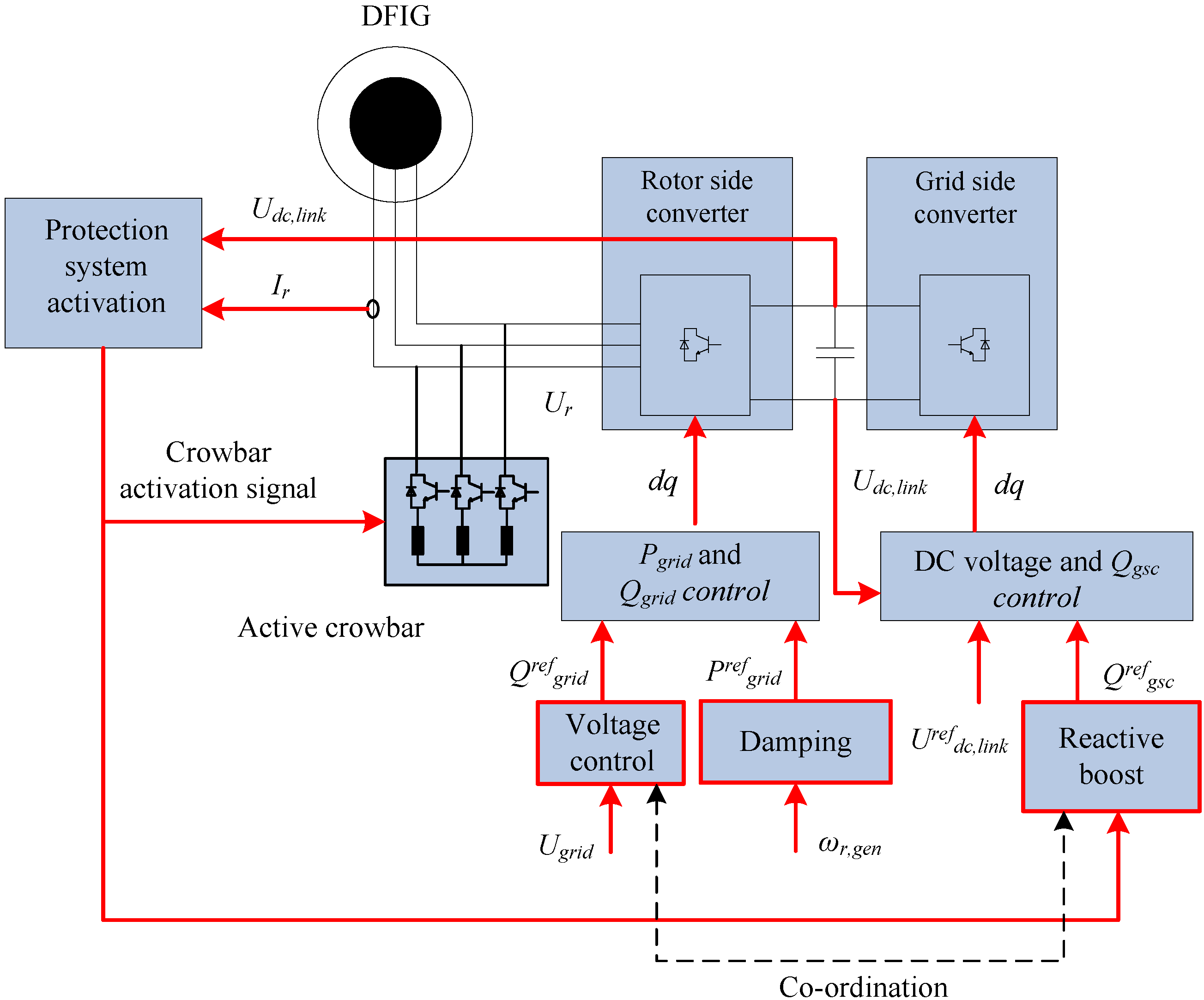
The electrical control system, depicted in
Figure 2, is essential for an effective behavior of a DFIG wind turbine during normal operation. Decoupled control of active and reactive power is applied through vector control techniques [
8], allowing for changes in the active and reactive power in the range of milliseconds. The RSC controls mainly the active and reactive power delivered to the grid, while the GSC ensures nominal voltage at the common DC-bus and a unity power factor operation of the converter. As illustrated in
Figure 2 and described in detail in [
9,
10,
11], the control of the converters is based on cascade control loops: a very fast inner current controller regulates the currents to the reference values that are specified by the outer slower power controller. The power controller implements the maximum power point (MPP) tracking strategy, which ensures power optimization at low wind speeds.
Figure 2.
Converter control and pitch control system of the DFIG wind turbine for normal operation.
Figure 2.
Converter control and pitch control system of the DFIG wind turbine for normal operation.
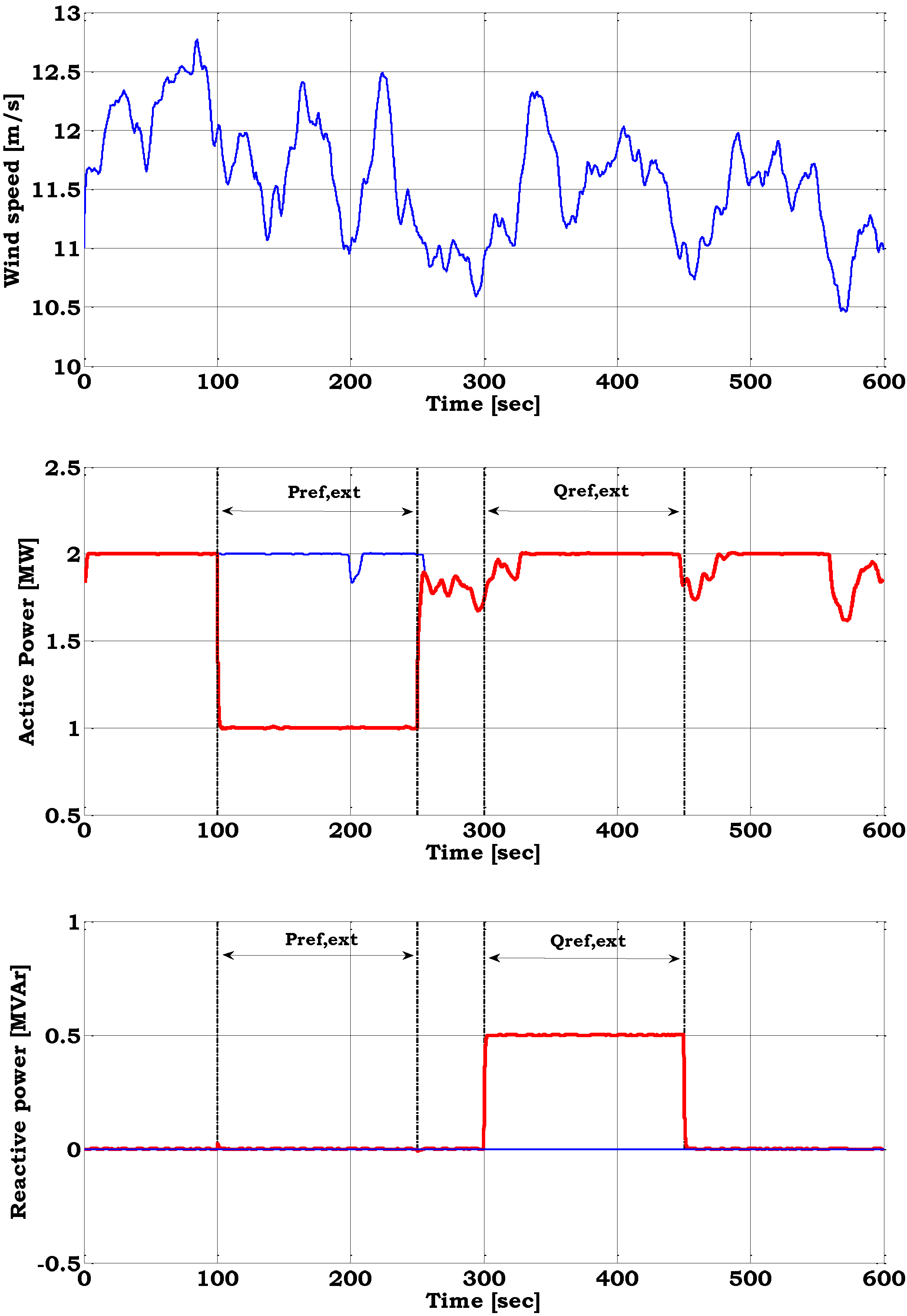
Figure 3 illustrates the ability of the variable speed wind turbine with DFIG to regulate its power production to an imposed reference value. A simulation is thus performed, where the reference power is reduced from 2 MW to 1 MW between 100 and 250 seconds and stepped back up again to 2 MW. The active and reactive power response is given for turbulent wind with a mean wind speed close to the rated. Notice that independent of the fluctuations of the wind, the active power is following its reference very well. For the first 300 s the reactive power is controlled to zero, following the unity power factor strategy. Then the reactive power reference is set to 0.5 MVar.
Figure 3 points out that the control strategy of the variable speed wind turbine model with DFIG is able to control active and reactive power independently to specific imposed values. This enhances the ability of modern wind farms to operate like conventional power plants.
Decoupled active and reactive power control enhance the DFIG operation for several requirements of power control, which are being introduced to grid codes nowadays, e.g., balance control, stop control, absolute power limitation, delta limitation, fast down regulation and ramp limitation to support system security.
Figure 3.
Stochastic wind speed, active power and reactive power during normal operation with (red line) and without (blue line) imposed reference values.
Figure 3.
Stochastic wind speed, active power and reactive power during normal operation with (red line) and without (blue line) imposed reference values.
2.2. Fault ride-through (FRT) capability
According to the fault ride-through requirements defined in most grid codes, wind turbines have to remain connected to the grid during voltage dips. The DFIG wind turbine configuration is sensitive to grid faults and requires special power converter protection, because high inrush stator and rotor currents can appear during grid faults. The protection of the converter against overcurrents, but also of the generator rotor and the dc-link against overvoltages, is ensured via the so-called crowbar. In principle, the crowbar is an external rotor impedance, coupled via the slip rings to the generator rotor. According to the strategy implemented in this survey, when the crowbar is triggered, the rotor side converter (RSC) is disabled and bypassed, and therefore the independent controllability of active and reactive power is lost. Since the grid side converter (GSC) is not directly connected to the generator windings, where the high transient currents occur, this converter is not blocked by the protection system during grid faults. When the crowbar is removed, the RSC is enabled again to control independently the active and reactive power.
In the case of a grid fault, the power reference is defined as the output of a damping controller [
7,
8]. When a fault is detected, the definition of the power reference is thus switched between the normal operation definition (
i.e., MPP) and the fault operation definition (damping controller).
Figure 4 depicts the control system applied for FRT as well as the voltage control, which will be described in the next section.
Figure 4.
Control system of the DFIG wind turbine for FRT and voltage control.
Figure 4.
Control system of the DFIG wind turbine for FRT and voltage control.
It is worth noting that during grid faults, the pitch control system is not able to damp the torsional oscillations, because of several delay mechanisms in the pitch [
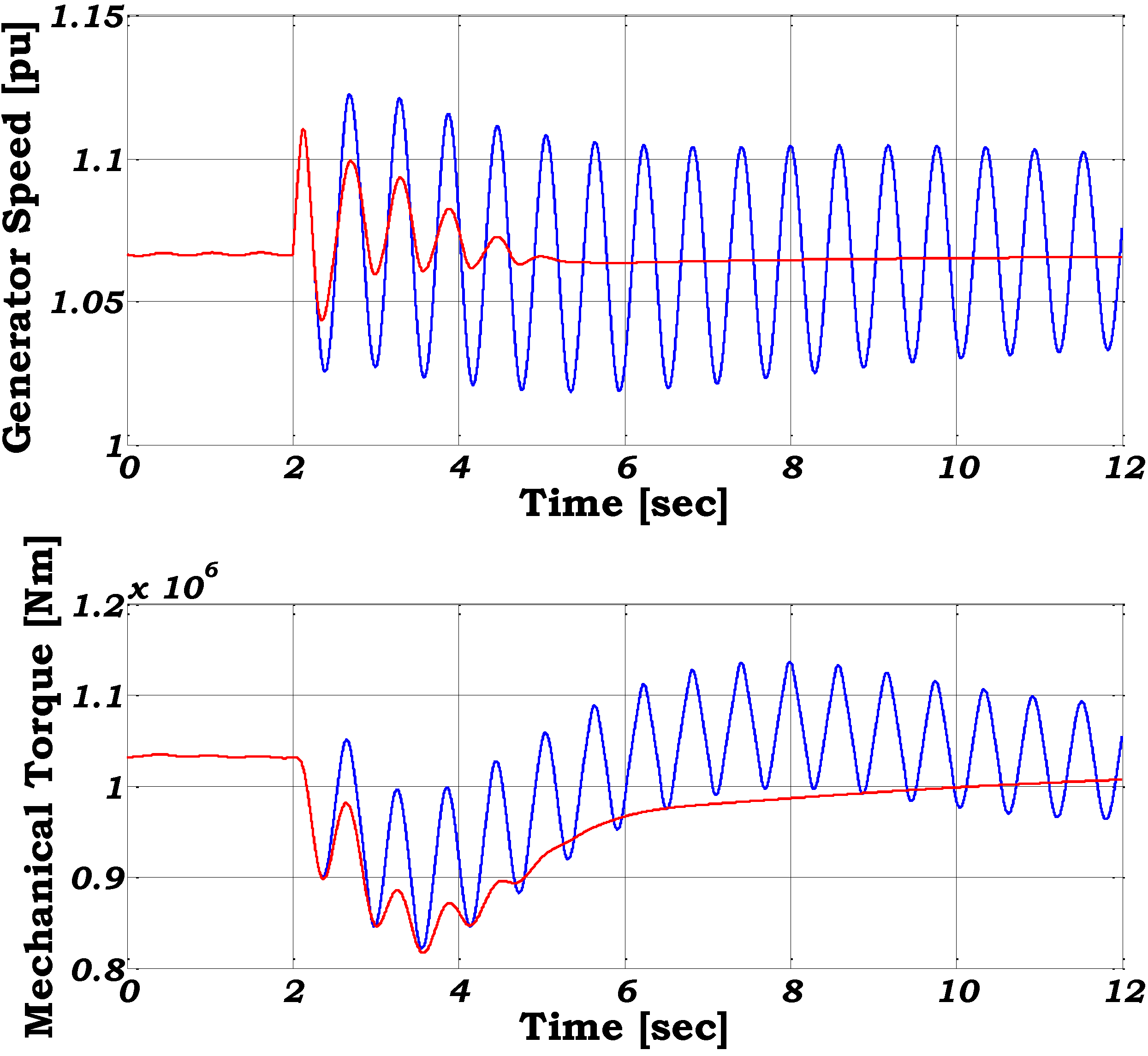
8]. The pitch control damps the slow frequency variations in the generator speed, while the damping controller is able to damp the fast oscillations in the generator speed. The effect of the damping controller both on the electrical and the mechanical parts of the turbine for a voltage dip down to 20% from the rated voltage with 100 ms duration is illustrated in
Figure 5.
The sudden drop of the voltage leads to drop in the stator and rotor flux, which result in a decrease of the electromagnetic torque. The drive train acts as a torsion spring and gets untwisted during faults and consequently the mechanical torque drops too. However, the mechanical torque drops slower than the electromagnetic torque and therefore the generator starts to accelerate. The effect of the damping controller, which acts directly on the active power reference signal, is very crucial. This controller damps actively the torsional excitations in the drive train system following the grid fault. When no damping controller is used, both the oscillations in the mechanical torque and in the generator speed remain undamped and would cause severe mechanical stress in the drive train, possibly leading to disconnection of the wind turbine by the protection system. The comparison reveals the positive effect of the damping controller on the response of the wind turbine.
Figure 5.
Generator speed and mechanical torque during voltage dip with (red line) and without damping controller (blue line).
Figure 5.
Generator speed and mechanical torque during voltage dip with (red line) and without damping controller (blue line).
2.3. Enhanced reactive power support
Wind farms are required to provide reactive power regulation like conventional power plants during power system voltage deviations. In the applied control strategy the RSC is the default reactive power source controlling the voltage at the Point of Common Coupling (PCC) during normal operation. At a fault instant,
i.e., a short circuit in the grid, the GSC is supplementing reactive power during the blocking of the RSC, which occurs when the crowbar is triggered. In this case the GSC continues its operation as STATCOM. After the removal of the crowbar the RSC starts to operate and the GSC is controlled to unity power factor as in normal operation [
12].
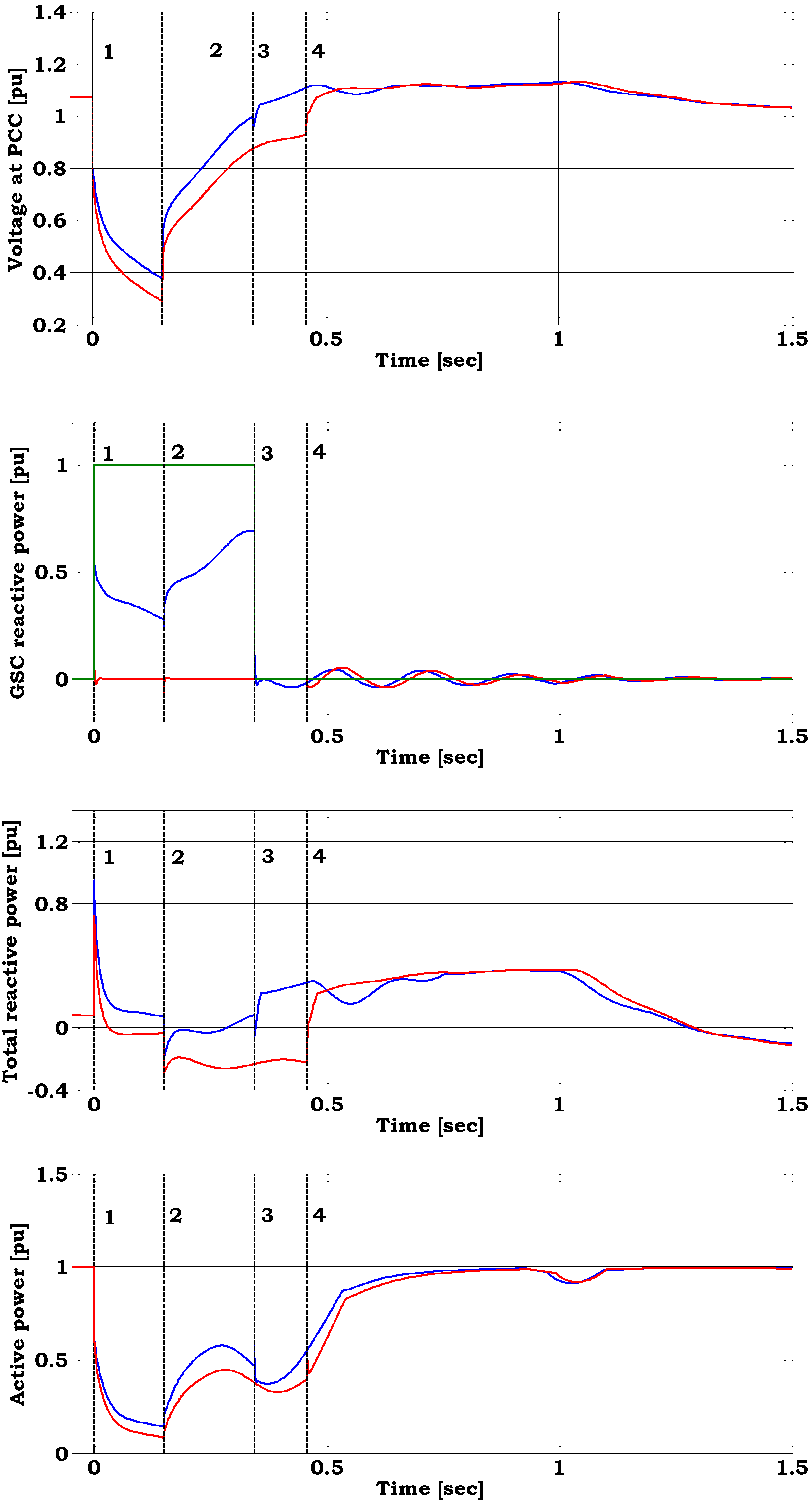
Figure 6 shows the results from a voltage dip at the terminals. The Short Circuit Ratio (SCR) calculated at the PCC is 1.9 and the R/X ratio in the PCC amounts to 0.14 [
13].
At the fault instance, the crowbar is coupled in the DFIG´s rotor circuit.
Figure 6 illustrates the response for two different control strategies: with and without reactive power boosting of the grid side converter. In the first case, during crowbar coupling the GSC contributes to reactive power supply and improves the voltage level. The reference power of the reactive power boosting for the GSC is set to 1 p.u.,
i.e., its maximum possible. Since the voltage level is significantly reduced during the fault, the grid side converter’s reactive power production capability is also reduced. Thus, the reference reactive power cannot be provided during the fault.
Figure 6.
Voltage at the Point of Common Coupling (PCC), GSC reactive power and reactive power reference (green line), total reactive power, active power when reactive power is provided (blue line) and not (red line) by the GSC – (1) fault instance, (2) fault clearance, (3) crowbar trigger off when GSC provides reactive power, (4) crowbar trigger off when GSC is reactive neutral
After fault clearing, when the voltage at the converter terminals re-establishes, the GSC is able to provide even more reactive power to the grid. Due to the reactive power demand of the generator, when the fault is cleared, the voltage does not completely recover immediately. The generator operates as a squirrel cage induction generator and has an increased magnetization demand during the voltage recovery. The generator absorbs reactive power from the grid, delaying the recovering process of the grid voltage. When the crowbar is removed and the rotor side converter is restarted, the voltage controller of the rotor side converter provides for reactive power supply re-establishing the voltage level.
2.4. Frequency-active power control
Among the ancillary services that modern wind turbines have to provide, frequency control appears as an emerging need, especially in non-interconnected power systems with increasing wind power penetration. In such power systems, load shedding regularly occurs due to large frequency deviations. Although sufficient spinning reserve by conventional units is ensured to overcome frequency problems, increasing wind power penetration is often challenging system security for non-interconnected systems.
Depending on their configuration wind turbines have a different response to frequency deviations.
Figure 7 and
Figure 8 illustrate the results from a study for an island system, Rhodes, for the case scenario when total wind power production is 28.2 MW (34%) in total 83 MW of demand [
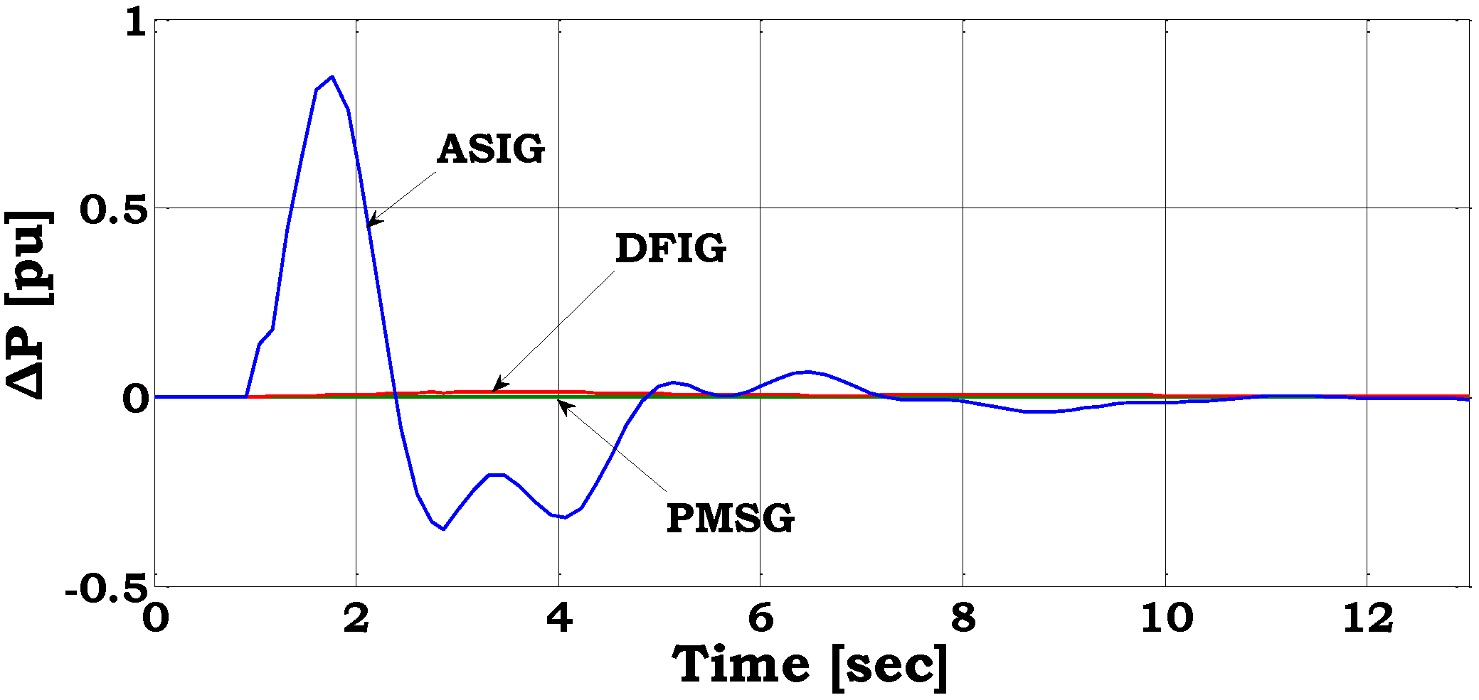
14]. The loss of the largest conventional unit in the system (21 MW) is simulated—production loss equal to 25% of the total demand. A comparison between the inertia responses of three different wind turbine configurations is given in
Figure 7 during medium wind speeds of 9–10 m/s. It is seen that the active stall induction generator (ASIG) wind turbines provide a significant dynamic response, while the response of the variable speed wind turbines—doubly fed induction generator and permanent magnet synchronous generator (PMSG)—is negligible.
Figure 7.
Change in active power production during a frequency drop for three wind turbine configurations.
Figure 7.
Change in active power production during a frequency drop for three wind turbine configurations.
As described in [
15,
16], the response of a DFIG wind turbine is very different than of ASIG wind turbines. Its inertial is mostly based on the applied control scheme acting on the converter connecting the rotor to the grid. Supplementary control attributes have been proposed in the literature in order to achieve active frequency control by variable speed wind turbines [
17,
18]. In this article two different frequency control methods are presented for the DFIG wind turbine configuration:
- ▪
Inertia Control
- ▪
Droop Control
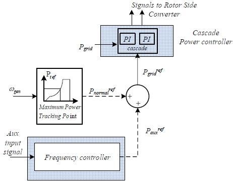
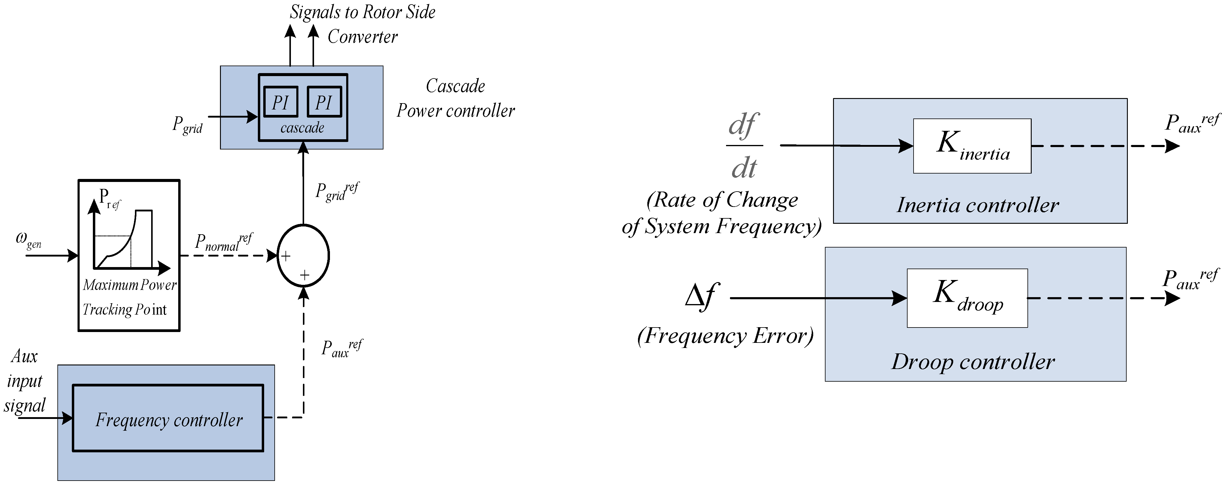
When inertia control is used, the inertial response of the DFIG is restored through an additional loop in the power reference block providing the active power reference signal to the Rotor Side Converter, (see
Figure 8). The DFIG wind turbine is ordered to adjust its power output when subjected to frequency deviations, based on the measurement of the rate of change of the frequency. This defines the additional power reference signal, which is added to the normal power reference provided by the MPP tracking controller [
14]. In droop control, the auxiliary input signal that defines the adjustment in the power production of the wind turbine is the actual error between the measured frequency of the system and the nominal frequency. This control method is similar to the primary frequency control applied to conventional generators.
Figure 8.
Frequency control scheme for the DFIG wind turbine configuration.
Figure 8.
Frequency control scheme for the DFIG wind turbine configuration.
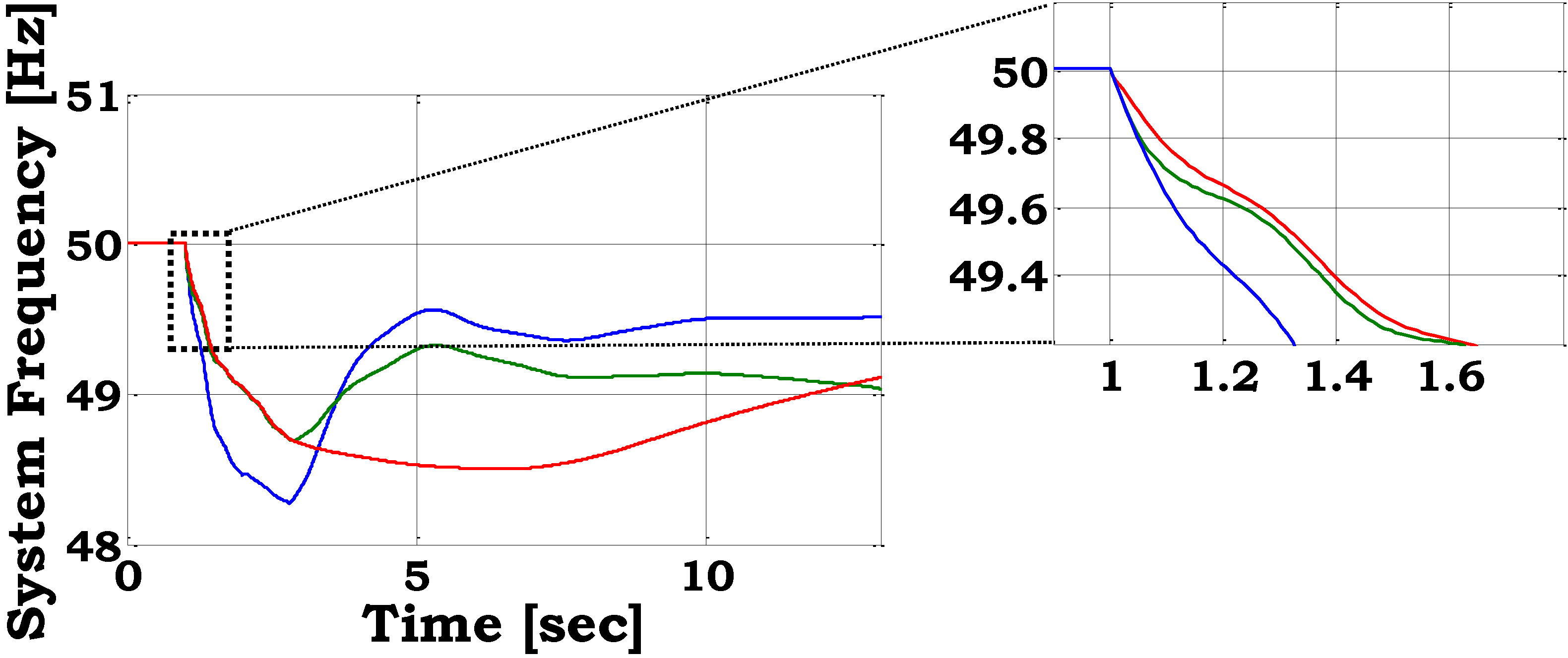
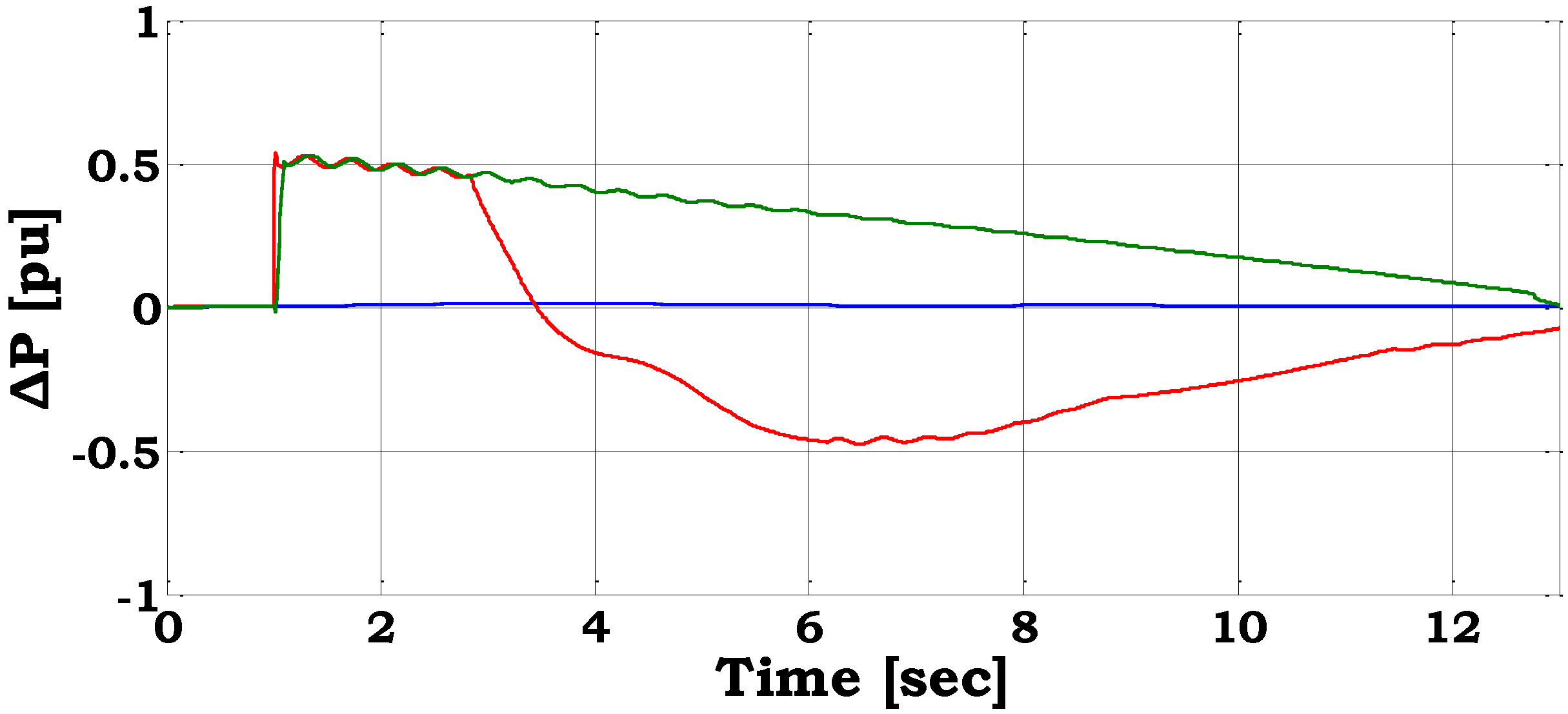
The system frequency for the different frequency control schemes implemented in wind farms equipped with DFIG wind turbines is shown. The initial frequency response during the first milliseconds after the frequency event is also illustrated for emphasis.
Figure 9.
Power system frequency and change in DFIG active power for largest unit loss—no auxiliary control (blue line), inertia control (red line), droop control (green line).
Figure 9.
Power system frequency and change in DFIG active power for largest unit loss—no auxiliary control (blue line), inertia control (red line), droop control (green line).
Notice that when no auxiliary frequency control is applied, the frequency drops below 48.5 Hz, leading to load shedding which prevents further frequency drop. In the other two cases, where the frequency control is activated in the DFIG wind farms, the load shedding is totally avoided. The optimum frequency drop in terms of minimum frequency is achieved through droop control.
The effect of auxiliary frequency control on the maximum rate of change of frequency is very crucial. As illustrated in
Figure 9, the initial rate of change of frequency is very high. The inertia of the system in this case is low because the number of the conventional generators connected to the system is reduced. The rate of change of frequency is close to 5 Hz/sec (in absolute value) when no auxiliary control is applied. Inertia control manages to reduce the rate to 3.8 Hz/sec, while droop control does not affect this rate.
Figure 9 illustrates also the change in the active power output of the wind farm during the frequency deviation for each one of the implemented methods.
