Surface-Modified Membrane as A Separator for Lithium-Ion Polymer Battery

Abstract
:1. Introduction
2. Fabrication of Separator for LIPB
2.1. General Features

| Commercially available separator membranes | |||||
|---|---|---|---|---|---|
| Celgard 2730 | Celgard 2400 | Celgard 2325 | Asahi Hipore | Tonen Setela | |
| Structure | single layer | single layer | trilayer | single layer | single layer |
| Material | PE | PP | PP-PE-PP | PE | PE |
| Thickness (μm) | 20 | 25 | 20 | 25 | 25 |
| Ionic resistivity (Ω/cm) | 2.23 | 2.55 | 1.85 | 2.66 | 2.56 |
| Porosity (%) | ~43 | ~40 | ~42 | ~40 | ~41 |
| Melting temperature (oC) | ~135 | ~165 | 135/165 | ~138 | ~137 |
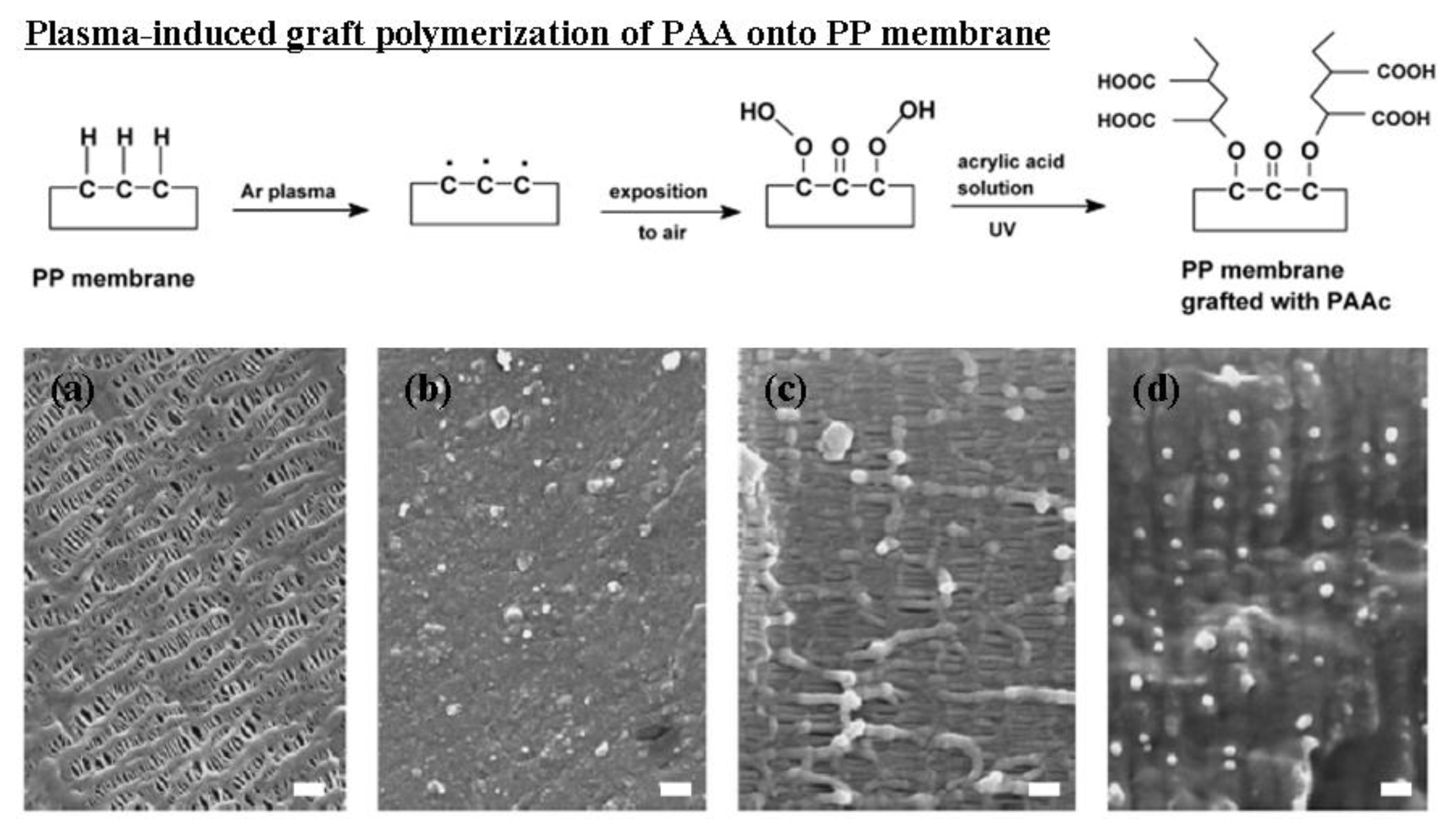
2.2. Surface Modification of Separators for LIPB

2.3. Plasma Treatment Techniques
| Plasma reactions | Gas |
|---|---|
| Cleaning | Oxygen |
| Ablation / Etching | Argon, Helium, Oxygen |
| Crosslinking | Oxygen-free noble gases such as argon and helium |
| Activation | Ammonia, Argon, Helium, Nitrogen, Tetrafluoromethane |
| Polymerization | Fluoro-monomers (Hexafluoroethylene, Perfluoroallylbenzene, Pentafluorostyrene, etc.) |
| Acrylic-monomers (Acrylic acid, Acrylonitrile, Alkyl acrylates, etc.) |

3. Plasma-Modified PE Membrane as A Separator for LIPB
3.1. General Fabrication
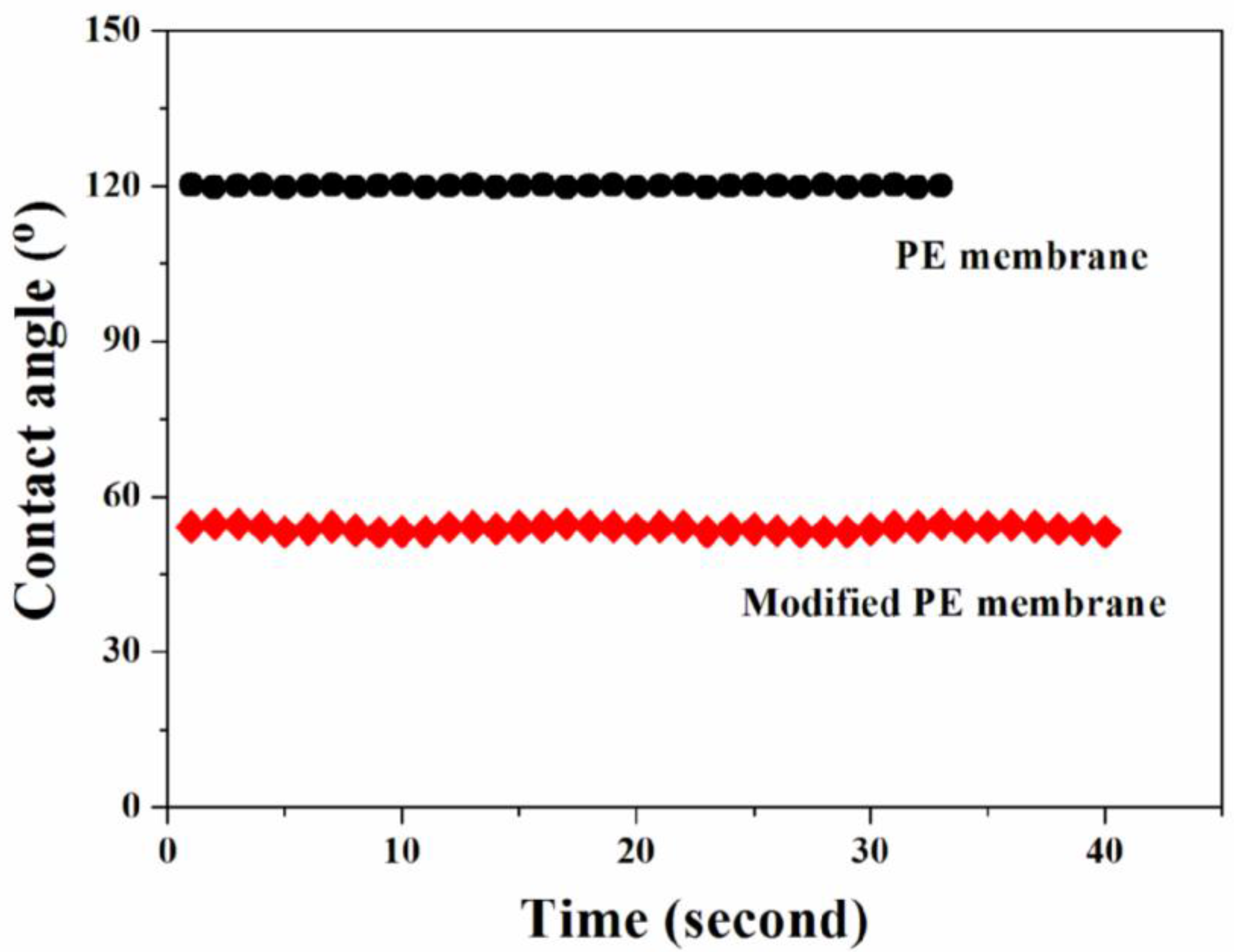
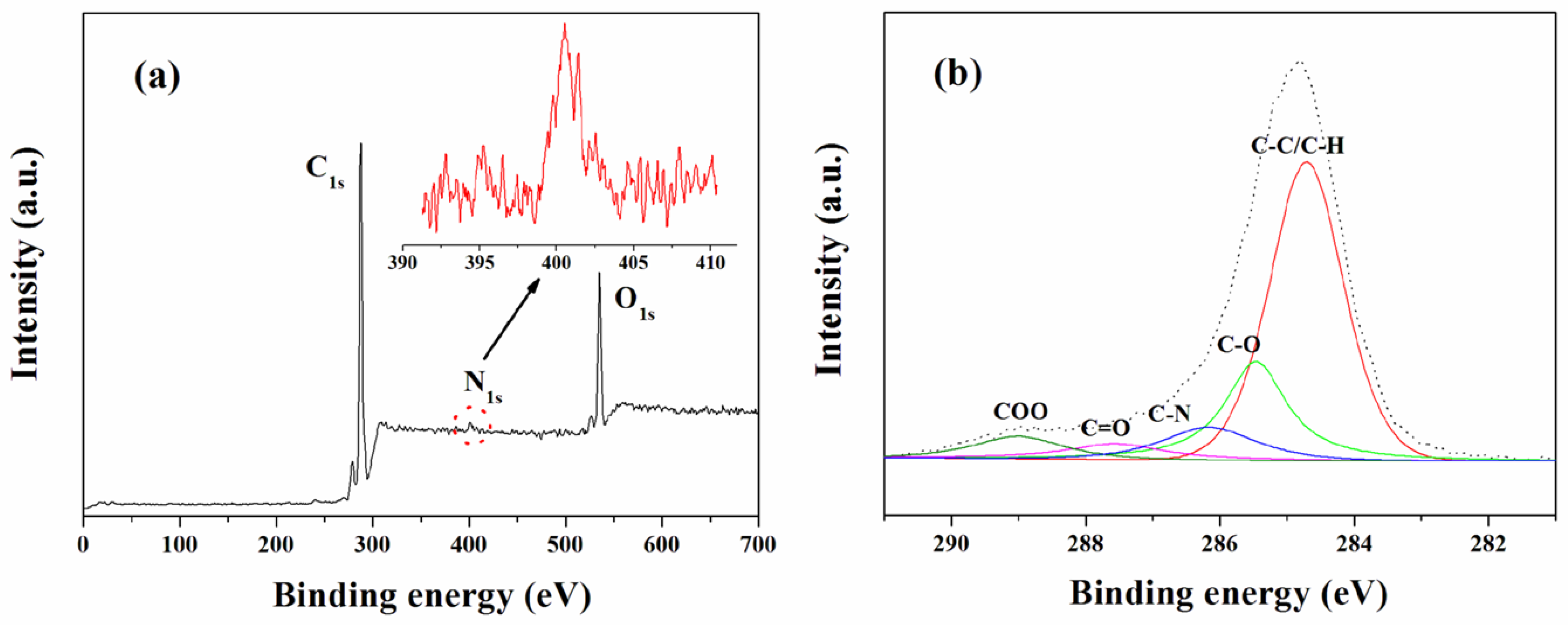
3.2. Surface Properties
| Materials | Functional groups (%) | ||||
|---|---|---|---|---|---|
| C–C/C–H | C–O | C–N | C=O | C–O–O | |
| PE membrane | 98.37 | 1.16 | - | 0.26 | 0.21 |
| Modified PE membrane | 63.77 | 17.54 | 7.55 | 5.00 | 6.14 |

| Materials | γs | γsd | γsp | Xp a |
|---|---|---|---|---|
| PE membrane | 30.3 | 28.9 | 1.4 | 0.05 |
| Modified PE membrane | 56.6 | 40.8 | 15.8 | 0.28 |
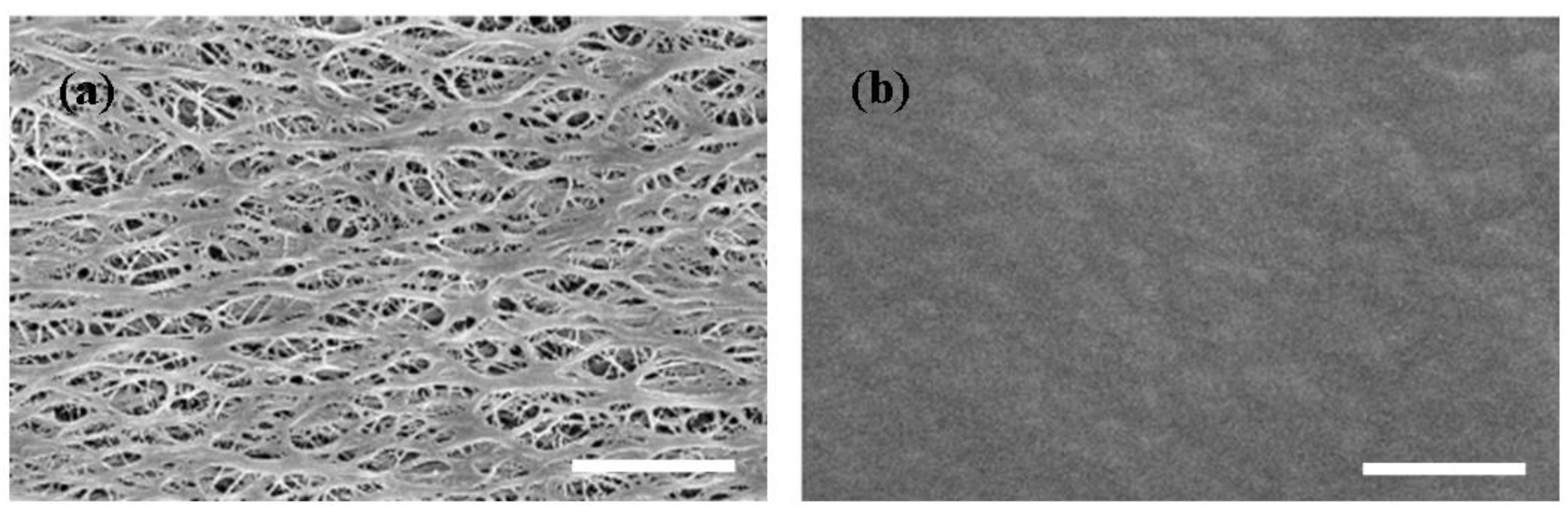
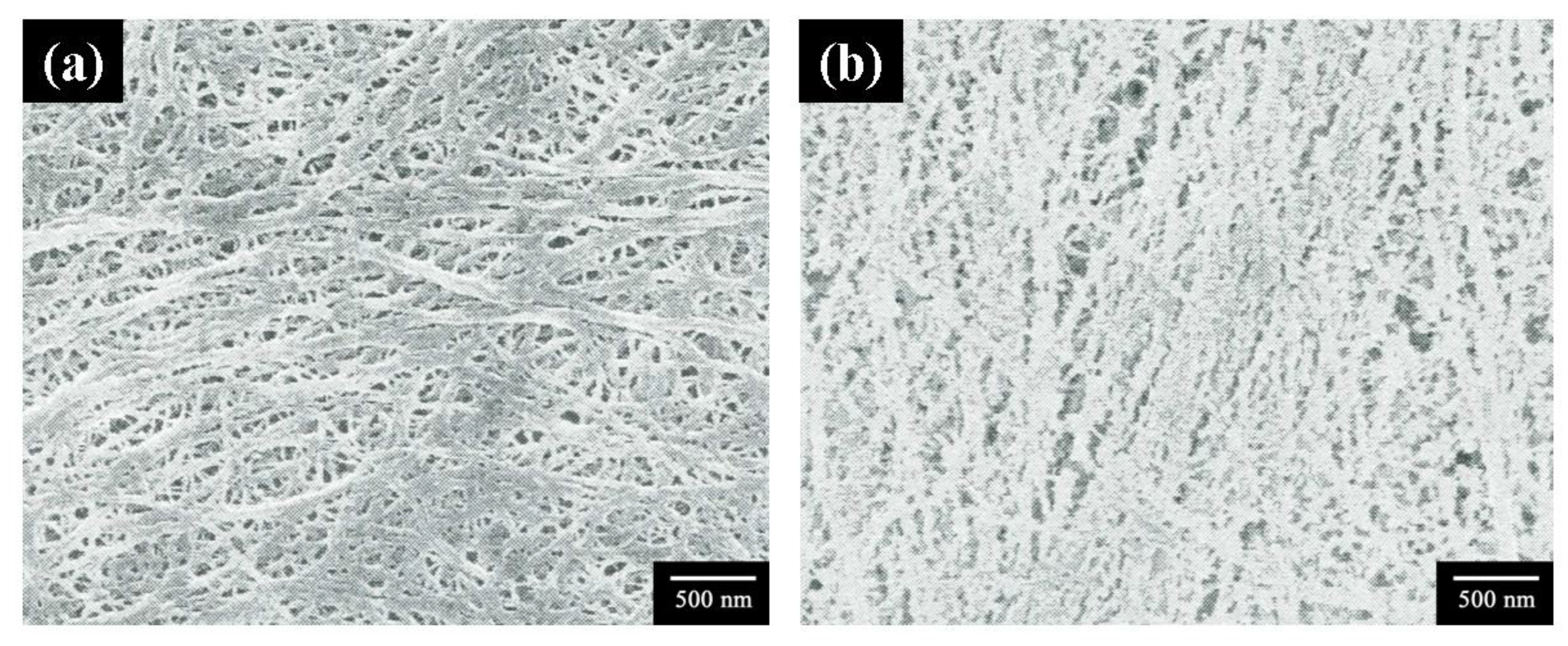
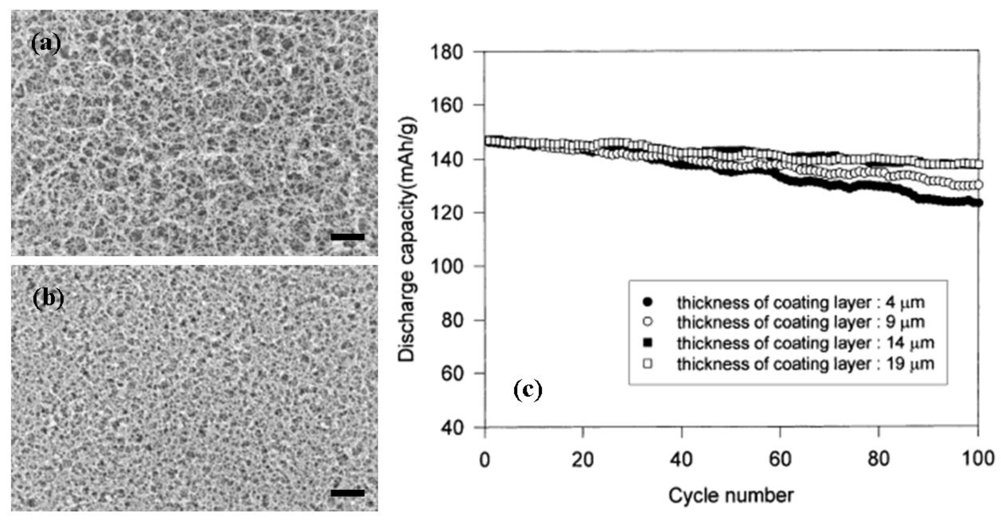
3.3. Morphology

3.4. Ionic Conductivity and Adhesion
| Materials | Ionic conductivity (mS/cm) a | Average load (N) b | Peel strength (N/m) b |
|---|---|---|---|
| PE membrane | 0.8 | 0.44 | 19.1 |
| Modified PE membrane | 1.4 | 0.52 | 22.6 |
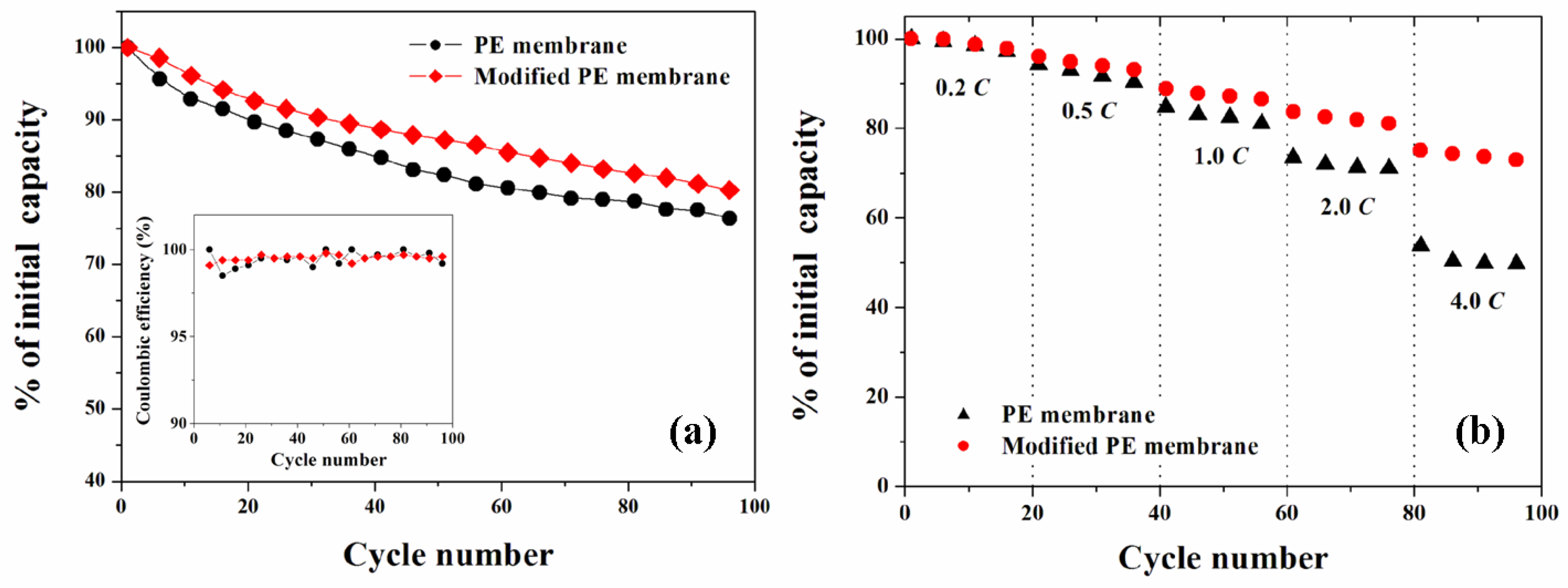
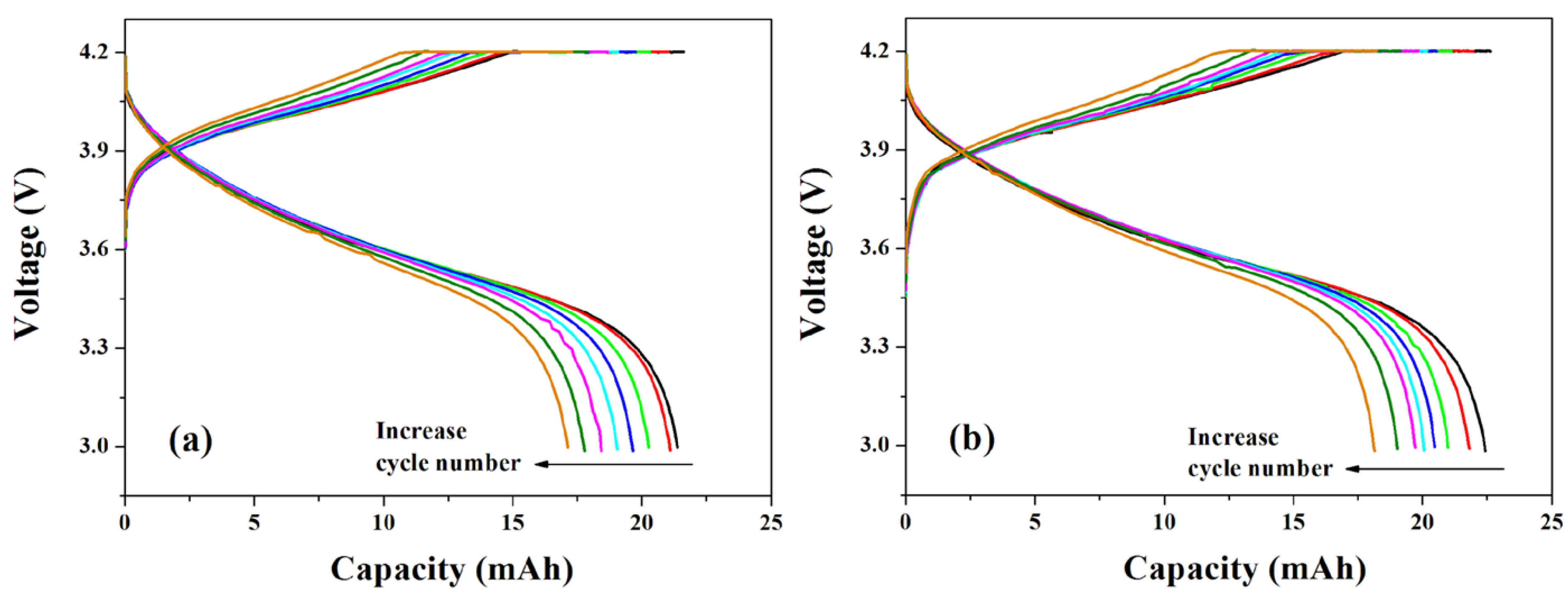
3.5. Cycle Performance of LIPB Cell

4. Concluding Remarks
References and Notes
- Scrosati, B. Applications of Electroactive Polymer; Chapman & Hall: London, UK, 1993. [Google Scholar]
- Linden, D.; Reddy, T.B. Handbook of Batteries; McGraw-Hill: New York, NY, USA, 2002. [Google Scholar]
- Besenhard, J.O. Handbook of Battery Materials; Wiley-VCH: Weinheim, DE, USA, 1999. [Google Scholar]
- Arora, P.; Zhang, Z. Battery separators. Chem. Rev. 2004, 104, 4419–4462. [Google Scholar] [CrossRef] [PubMed]
- Zhang, S.S. A review on the separators of liquid electrolyte Li-ion batteries. J. Power Sources 2007, 164, 351–364. [Google Scholar] [CrossRef]
- Wang, H.P.; Huang, H.; Wunder, S.L. Novel microporous poly(vinylidene fluoride) blend electrolytes for lithium-ion batteries. J. Electrochem. Soc. 2000, 147, 2853–2861. [Google Scholar] [CrossRef]
- Lee, Y.M.; Kim, J.W.; Choi, N.S.; Lee, J.A.; Seol, W.H.; Park, J.K. Novel separator based on PVdF and PE non-woven matrix for rechargeable lithium batteries. J. Power Sources 2005, 139, 235–241. [Google Scholar] [CrossRef]
- Croce, F.; Appetecchi, G.B.; Persi, L.; Scrosati, B. Nanocomposite polymer electrolytes for lithium batteries. Nature 1998, 394, 456–458. [Google Scholar]
- Michot, T.; Nishimoto, A.; Watanabe, M. Electrochemical properties of polymer gel electrolytes based on poly(vinylidene fluoride) copolymer and homopolymer. Electrochim. Acta 2000, 45, 1347–1360. [Google Scholar] [CrossRef]
- Huang, H.; Wunder, S.L. Ionic conductivity of microporous PDVF-HFP/PS polymer blends. J. Electrochem. Soc. 2001, 148, A279–A283. [Google Scholar] [CrossRef]
- Song, J.Y.; Cheng, C.L.; Wang, Y.Y.; Wan, C.C. Microstructure of poly(vinylidene fluoride)-based polymer electrolyte and its effect on transport properties. J. Electrochem. Soc. 2002, 149, A1230–A1236. [Google Scholar] [CrossRef]
- Saito, Y.; Stephan, A.M.; Kataoka, H. Ion conduction mechanisms of lithium gel polymer electrolytes investigated by the conductivity and diffusion coefficient. Solid State Ionics 2003, 160, 149–153. [Google Scholar] [CrossRef]
- Abraham, K.M.; Alamgir, M.; Hoffman, D.K. Polymer electrolytes reinforced by Celgard℘ membranes. J. Electrochem. Soc. 1995, 142, 683–687. [Google Scholar] [CrossRef]
- Kim, D.W.; Ko, J.M.; Chun, J.H.; Kim, S.H.; Park, J.K. Electrochemical performances of lithium-ion cells prepared with polyethylene oxide-coated separators. Electrochem. Commun. 2001, 3, 535–538. [Google Scholar] [CrossRef]
- Wang, Y.; Travas-Sejdic, J.; Steiner, R. Polymer gel electrolyte supported with microporous polyolefin membranes for lithium ion polymer battery. Solid State Ionics 2002, 148, 443–449. [Google Scholar]
- Tsuneda, S.; Saito, K.; Furusaki, S.; Sugo, T.; Makuuchi, K. Simple introduction of sulfonic acid group onto polyethylene by radiation-induced cografting of sodium styrenesulfonate with hydrophillic monomers. Ind. Eng. Chem. Res. 1993, 32, 1464–1470. [Google Scholar] [CrossRef]
- Higuchi, H.; Matsushita, K.; Ezoe, M.; Shinomura, T. Porous film, process for producing the same and use of the same. US Patent 5,385,777, 1995. [Google Scholar]
- Sogo, H. Separator for a battery using an organic electrolytic solution and method for preparing the same. US Patent 5,641,565, 1997. [Google Scholar]
- Hashimoto, A.; Yagi, K.; Mantoku, H. Porous film of high molecular weight polyolefin and process for producing same. US Patent 6,048,607, 2000. [Google Scholar]
- Fisher, H.M.; Wensley, C.G. Polypropylene microporous membrane for battery separator. US Patent 6,368,742, 2002. [Google Scholar]
- Lee, S.Y.; Ahn, B.I.; Im, S.G.; Park, S.Y.; Song, H.S.; Kyung, Y.J. High crystalline polypropylene microporous membrane, multi-component microporous membrane and methods for preparing the same. US Patent 6,830,849, 2004. [Google Scholar]
- Bierenbaum, H.S.; Isaacson, R.B.; Druin, M.L.; Plovan, S.G. Microporous polymeric films. Ind. Eng. Chem. Prod. Res. Dev. 1974, 13, 2–9. [Google Scholar] [CrossRef]
- Kim, S.S.; Lloyd, D.R. Microporous membrane formation via thermally-induced phase separation. III: Effect of thermodynamic interactions on the structure of isotactic polypropylene membranes. J. Membr. Sci. 1991, 64, 13–29. [Google Scholar] [CrossRef]
- Yu, W.C.; Dwiggins, C.F. Methods of making cross-ply microporous membrane battery separator, and the battery separators made thereby. US Patent 5,667,911, 1997. [Google Scholar]
- Yu, T.H. Trilayer battery separator. US Patent 6,080,507, 2000. [Google Scholar]
- Chandavasu, C.; Xanthos, M.; Sirkar, K.K.; Gogos, C. Preparation of microporous films from, immiscible blends via melt processing and stretching. US Patent 6,824,680, 2004. [Google Scholar]
- Yu, W.C. Continuous methods of making microporous battery separators. US Patent 6,878,226, 2005. [Google Scholar]
- Kesting, R.E. Synthetic Polymeric Membranes; John Wiley & Sons: New York, NY, USA, 1985. [Google Scholar]
- Weighall, M.J. Recent advances in polyethylene separator technology. J. Power Sources 1991, 34, 257–268. [Google Scholar] [CrossRef]
- Yen, Y.L.; Lopatin, G.; Malarkey, H.; Soane, D. Process for producing fluorocarbon membranes and membrane product. US Patent 5,032,274, 1991. [Google Scholar]
- Chung, T.S.; Foley, P.; Kafchinski, E.R. Development of poly(ethylene tetrafluoroethylene) microporous film for advanced batteries. J. Mater. Sci.-Mater. Electron. 1993, 4, 259–266. [Google Scholar] [CrossRef]
- Kim, J.J.; Kim, S.S.; Hwang, J.R.; Suh, S.B. Process for the preparation of porous polyolefin separation membranes via thermally-induced phase separation. US Patent 5,250,240, 1993. [Google Scholar]
- Takita, K.; Kono, K.; Takashima, T.; Okamoto, K. Microporous polyolefin membrane and method of producing same. US Patent 5,051,183, 1991. [Google Scholar]
- Ihm, D.W.; Noh, J.G.; Kim, J.Y. Effect of polymer blending and drawing conditions on properties of polyethylene separator prepared for Li-ion secondary battery. J. Power Sources 2002, 109, 388–393. [Google Scholar] [CrossRef]
- Taskier, H.T. Hydrophilic polymer coated microporous membranes capable of use as a battery separator. US Patent 4,359,510, 1982. [Google Scholar]
- Gineste, J.L.; Pourcelly, G. Polypropylene separator grafted with hydrophilic monomers for lithium batteries. J. Membr. Sci. 1995, 10, 155–164. [Google Scholar] [CrossRef]
- Senyarich, S.; Viaud, P. Method of forming a separator for alkaline electrolyte secondary electric cell. US Patent 6,042,970, 2000. [Google Scholar]
- Choi, S.H.; Park, S.Y.; Nho, Y.C. Electrochemical properties of polyethylene membrane modified with carboxylic acid group. Radiat. Phys. Chem. 2000, 57, 179–186. [Google Scholar] [CrossRef]
- Choi, S.H.; Kang, H.J.; Ryu, E.N.; Lee, K.P. Electrochemical properties of polyolefin nonwoven fabric modified with carboxylic acid group for battery separator. Radiat. Phys. Chem. 2001, 60, 495–502. [Google Scholar] [CrossRef]
- Ko, J.M.; Min, B.G.; Kim, D.W.; Ryu, K.S.; Kim, K.M.; Lee, Y.G.; Chang, S.H. Thin-film type Li-ion battery, using a polyethylene separator grafted with glycidyl methacrylate. Electrochim. Acta 2004, 5, 367–370. [Google Scholar] [CrossRef]
- Gao, K.; Hu, X.G.; Yi, T.F.; Dai, C.S. PE-g-MMA polymer electrolyte membrane for lithium polymer battery. Electrochim. Acta 2006, 52, 443–449. [Google Scholar] [CrossRef]
- Kim, D.W.; Noh, K.A.; Chun, J.H.; Kim, S.H.; Ko, J.M. Highly conductive polymer electrolytes supported by microporous membrane. Solid State Ionics 2001, 1, 329–337. [Google Scholar] [CrossRef]
- Eschbach, F.O.; Oliver, M. Gel electrolyte bonded rechargeable electrochemical cell and method of making same. US Patent 5,681,357, 1997. [Google Scholar]
- Hamano, K.; Shiota, H.; Shiraga, S.; Aihara, S.; Yoshida, Y.; Murai, M.; Inuzuka, T. Lithium-ion secondary battery and method of fabricating thereof. US Patent 5,981,107, 1999. [Google Scholar]
- Jeong, Y.B.; Kim, D.W. Effect of thickness of coating layer on polymer-coated separator on cycling performance of lithium-ion polymer cells. J. Power Sources 2004, 1, 256–262. [Google Scholar] [CrossRef]
- Kim, J.Y.; Kim, S.K.; Lee, S.J.; Lee, S.Y.; Lee, H.M.; Ahn, S. Preparation of micro-porous gel polymer for lithium ion polymer battery. Electrochim. Acta 2004, 5, 363–366. [Google Scholar] [CrossRef]
- Kim, D.W.; Oh, B.; Park, J.H.; Sun, Y.K. Gel-coated membranes for lithium-ion polymer batteries. Solid State Ionics 2000, 138, 41–49. [Google Scholar] [CrossRef]
- Oh, J.S.; Kang, Y.K.; Kim, D.W. Lithium polymer batteries using the highly porous membrane filled with solvent-free polymer electrolyte. Electrochim. Acta 2006, 52, 1567–1570. [Google Scholar] [CrossRef]
- Morigaki, K.; Kabuto, N.; Haraguchi, K. Manufacturing method of a separator for a lithium secondary battery and an organic electrolyte lithium secondary battery using the same separator. U.S. Patent 5,597,659, 1997. [Google Scholar]
- Liston, E.M.; Martinu, L.; Werheimer, M.R. Plasma Surface Modification of Polymers for Improved Adhesion: A Critical Review. In Plasma Surface Modification of Polymers: Relevance to Adhesion; Strobel, M., Lyons, C.S., Mittal, K.L., Eds.; VSP: Zeist, The Netherlands, 1994. [Google Scholar]
- Kaplan, S.L.; Rose, P.W. Plasma Surface Treatmen. In Coatings Technology Handbook; Tracton, A.A., Ed.; CRC Press: Boca Raton, FL, USA, 2006. [Google Scholar]
- Shishoo, R. Plasma Technologies for Textiles; Woodhead Publishing: Cambridge, UK, 2007. [Google Scholar]
- Kubota, T. Secondary battery with graft-polymerized separator. US Patent 5,270,137, 1993. [Google Scholar]
- Tsukiashi, M.; Teraoka, H.; Hata, K.; Tajima, M. Battery separator and manufacturing method thereof, and alkali secondary battery having the separator incorporated therein. US Patent 6,723,809, 2003. [Google Scholar]
- Ciszewski, A.; Gancarz, I.; Kunicki, J.; Marek, B. Plasma-modified polypropylene membranes as separators in high power alkaline batteries. Surf. Coat. Technol. 2006, 201, 3676–3684. [Google Scholar] [CrossRef]
- Ciszewski, A.; Kunicki, J.; Gancarz, I. Usefulness of microporous hydrophobic polypropylene membranes after plasma-induced graft polymerization of acrylic acid for high power nickel-cadmium batteries. Electrochim. Acta 2007, 5, 5207–5212. [Google Scholar] [CrossRef]
- Choi, S.S.; Lee, Y.S.; Joo, C.W.; Lee, S.G.; Park, J.K.; Han, K.S. Electrospun PVDF nanofiber web as polymer electrolyte or separator. Electrochim. Acta 2004, 50, 339–343. [Google Scholar] [CrossRef]
- Kim, J.Y.; Lee, Y.; Lim, D.Y. Plasma-modified polyethylene membrane as a separator for lithium-ion polymer battery. Electrochim. Acta 2009, 5, 3714–3719. [Google Scholar] [CrossRef]
- Choe, H.S.; Carroll, B.G.; Pasquariello, D.M.; Abraham, K.M. Characterization of some polyacrylonitrile-based electrolytes. Chem. Mater. 1997, 9, 369–379. [Google Scholar] [CrossRef]
- Akashi, H.; Tanaka, K.; Sekai, K. An ionic conductivity and spectroscopic study of ionic transport mechanism in fire-retardant polyacrylonitrile-based gel electrolytes for Li polymer batteries. J. Electrochem. Soc. 1998, 145, 881–887. [Google Scholar] [CrossRef]
- Svorcik, V.; Kolarova, K.; Slepicka, P.; Mackova, A.; Novotna, M.; Hnatowicz, V. Modification of surface properties of high and low density polyethylene by Ar plasma discharge. Polym. Degrad. Stab. 2006, 91, 1219–1225. [Google Scholar] [CrossRef]
- Owens, D.K.; Wendt, R.C. Estimation of the surface free energy of polymers. J. Appl. Polym. Sci. 1969, 13, 1741–1747. [Google Scholar] [CrossRef]
- Konloch, A.J. Adhesion and Adhesives: Science and Technology; Springer: Berlin, Germany, 1987. [Google Scholar]
- Novak, I.; Pollak, V.; Chodak, I. Study of surface properties of polyolefins modified by corona discharge plasma. Plasma Process. Polym. 2006, 3, 355–364. [Google Scholar] [CrossRef]
- Novak, I.; Elyashevich, G.K.; Chodak, I.; Olifirenko, A.S.; Steviar, M.; Spirkova, M.; Saprykina, N.; Vlasova, E.; Kleinova, A. Polymer matrix of polyethylene porous films functionalized by electrical discharge plasma. Eur. Polym. J. 2008, 44, 2702–2707. [Google Scholar] [CrossRef]
- Wu, S. Polymer Interface and Adhesion; Marcel Dekker: New York, NY, USA, 1982. [Google Scholar]
- Kim, S.H.; Kim, J.Y.; Kim, H.S.; Cho, H.N. Ionic conductivity of polymer electrolytes based on phosphate and polyether copolymers. Solid State Ionics 1999, 1, 63–71. [Google Scholar] [CrossRef]
- Kim, J.Y.; Kim, S.H. Ionic conduction behavior of network polymer electrolytes based on phosphate and polyether copolymers. Solid State Ionics 1999, 1, 91–99. [Google Scholar] [CrossRef]
- Kim, D.W.; Noh, K.A.; Min, H.S.; Kang, D.W.; Sun, Y.K. Porous polyacrylonitrile membrane for lithium-ion cells. Electrochem. Solid-State Lett. 2002, 5, A63–A66. [Google Scholar] [CrossRef]
- Morzilli, S.; Bonini, F.; Scrosati, B. Characteristics of the lithium electrode in organic and polymeric electrolytes. Electrochim. Acta 1987, 32, 961–964. [Google Scholar] [CrossRef]
- Aurbach, D.; Weissman, I.; Zaban, A.; Chusid, O. Correlation between surface chemistry, morphology, cycling efficiency and interfacial properties of Li electrodes in solutions containing different Li salts. Electrochim. Acta 1994, 39, 51–71. [Google Scholar] [CrossRef]
- Zhang, S.S.; Ding, M.S.; Xu, K.; Allen, J.; Jow, T.R. Understanding of solid electrolyte interface film formation on graphite electrodes. Electrochem. Solid-State Lett. 2001, 4, A206–A208. [Google Scholar] [CrossRef]
© 2010 by the authors; licensee MDPI, Basel, Switzerland. This article is an open-access article distributed under the terms and conditions of the Creative Commons Attribution license (http://creativecommons.org/licenses/by/3.0/).
Share and Cite
Kim, J.Y.; Lim, D.Y. Surface-Modified Membrane as A Separator for Lithium-Ion Polymer Battery. Energies 2010, 3, 866-885. https://doi.org/10.3390/en3040866
Kim JY, Lim DY. Surface-Modified Membrane as A Separator for Lithium-Ion Polymer Battery. Energies. 2010; 3(4):866-885. https://doi.org/10.3390/en3040866
Chicago/Turabian StyleKim, Jun Young, and Dae Young Lim. 2010. "Surface-Modified Membrane as A Separator for Lithium-Ion Polymer Battery" Energies 3, no. 4: 866-885. https://doi.org/10.3390/en3040866