Abstract
We have developed a new wind turbine system that consists of a diffuser shroud with a broad-ring brim at the exit periphery and a wind turbine inside it. The shrouded wind turbine with a brimmed diffuser has demonstrated power augmentation by a factor of about 2–5 compared with a bare wind turbine, for a given turbine diameter and wind speed. This is because a low-pressure region, due to a strong vortex formation behind the broad brim, draws more mass flow to the wind turbine inside the diffuser shroud.
1. Introduction
For the application of an effective energy resource in the future, the limitation of fossil fuels is clear and the security of alternative energy sources is an important subject. Furthermore, due to concerns for environmental issues, i.e., global warming, etc., the development and application of renewable and clean new energy are strongly expected. Among others, wind energy technologies have developed rapidly and are about to play a big role in a new energy field. However, in comparison with the overall demand for energy, the scale of wind power usage is still small; especially, the level of development in Japan is extremely small. As for the reasons, various causes are conceivable. For example, the limited local area suitable for wind power plants, the complex terrain compared to that in European or North American countries and the turbulent nature of the local wind are pointed out. Therefore, the introduction of a new wind power system that produces higher power output even in areas where lower wind speeds and complex wind patterns are expected is strongly desired.
Wind power generation is proportional to the wind speed cubed. Therefore, a large increase in output is brought about if it is possible to create even a slight increase in the velocity of the approaching wind to a wind turbine. If we can increase the wind speed by utilizing the fluid dynamic nature around a structure or topography, namely if we can concentrate the wind energy locally, the power output of a wind turbine can be increased substantially. Although there have been several studies of collecting wind energy for wind turbines reported so far [1,2,3,4,5,6,7], it has not been an attractive research subject conventionally. Unique research that was carried out intensively in the past is the examination of a diffuser-augmented wind turbine (DAWT) by Gilbert et al. [2], Gilbert and Foreman [3], Igra [4] and others around 1980. In these studies, there was a focus on concentrating wind energy in a diffuser with a large open angle, a boundary layer controlled with several flow slots was employed to realize a flow that goes along the inside surface of the diffuser. Thus, the method of boundary layer control prevents pressure loss by flow separation and increases the mass flow inside the diffuser. Based on this idea, a group in New Zealand [5,6] developed the Vortec 7 diffuser augmented wind turbine. They used a multi-slotted diffuser to prevent separation within the diffuser. Bet and Grassmann [7] developed a shrouded wind turbine with a wing-profiled ring structure. It was reported that their DAWT showed an increase in power output by the wing system by a factor of 2.0, compared to the bare wind turbine. Although several other ideas have been reported so far, most of them do not appear to be reaching commercialization.
The present study, regarding the development of a wind power system with high output, aims at determining how to collect the wind energy efficiently and what kind of wind turbine can generate energy effectively from the wind. There appears hope for utilizing the wind power in a more efficient way. In the present study, this concept of accelerating the wind was named the "wind-lens" technology. For this purpose, we have developed a diffuser-type structure that is capable of collecting and accelerating the approaching wind. Namely, we have devised a diffuser shroud with a large brim that is able to increase the wind speed from approaching wind substantially by utilizing various flow characteristics, e.g., the generation of low pressure region by vortex formation, flow entrainment by vortices and so on, of the inner or peripheral flows of a diffuser shroud equipped with a brim. Although it adopts a diffuser-shaped structure surrounding a wind turbine like the others [1,2,3,4,5,6,7], the feature that distinguishes it from the others is a large brim attached at the exit of diffuser shroud. Furthermore, we placed a wind turbine inside the diffuser shroud equipped with a brim and evaluated the power output generated. As a result, the shrouded wind turbine equipped with a brimmed diffuser demonstrated power augmentation for a given turbine diameter and wind speed by a factor of about 4–5 compared to a standard micro wind turbine.
Furthermore, for the practical application to a small- and mid-size wind turbine, we have been developing a compact-type brimmed diffuser. The combination of a diffuser shroud and a brim is largely modified from the one with a long diffuser with a large brim. The compact “wind-lens turbines” showed power augmentation of 2–3 times as compared to a bare wind turbine. The application examples for a few projects are introduced.
2. Development of a Collection-Acceleration Device for Wind (Diffuser Shroud Equipped with a Brim, Called “Wind-Lens”)
2.1. Selection of a Diffuser-Type Structure as the Basic Form
A large boundary-layer wind tunnel of the Research Institute for Applied Mechanics, Kyushu University, was used. It has a measurement section of 15 m long × 3.6 m wide × 2 m high with a maximum wind velocity of 30 m/s. Two types of hollow-structure models, a nozzle and a diffuser type, were tested (Figure 1). The distributions of wind velocity U and static pressure p along the central axis of the hollow-structure model were measured with an I-type hot-wire and a static-pressure tube. In the case of using a big hollow-structure model, paying attention to the blockage effect in the wind tunnel, we removed the ceiling and both side walls ranging 6 m in the center portion of the measurement section. Namely, we used our wind tunnel with an open-type test section to avoid the blockage effect. The smoke-wire technique was employed for the flow visualization experiment.
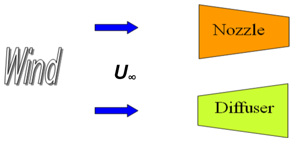
Figure 1.
Two types of hollow structures.
The experiments revealed that a diffuser-shaped structure can accelerate the wind at the entrance of the body, as shown in Figure 2 [8,9,10]. The reason is clarified through the flow visualization, as shown in Figure 3. Figure 3a,b shows the flows inside and outside the nozzle- and diffuser-type models. The flow is from left to right. As seen in the Figure 3(a), the wind tends to avoid the nozzle-type model, while the wind flows into the diffuser-type model as it is inhaled, as seen in Figure 3(b).
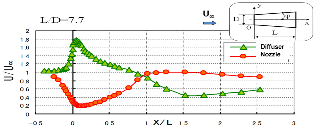
Figure 2.
Wind velocity distribution on the central axis of a hollow structure, L/D = 7.7. The area ratios μ (outlet area/inlet area) of the hollow-structure models are 1/4 and 4 for the nozzle- and diffuser-type models, respectively.
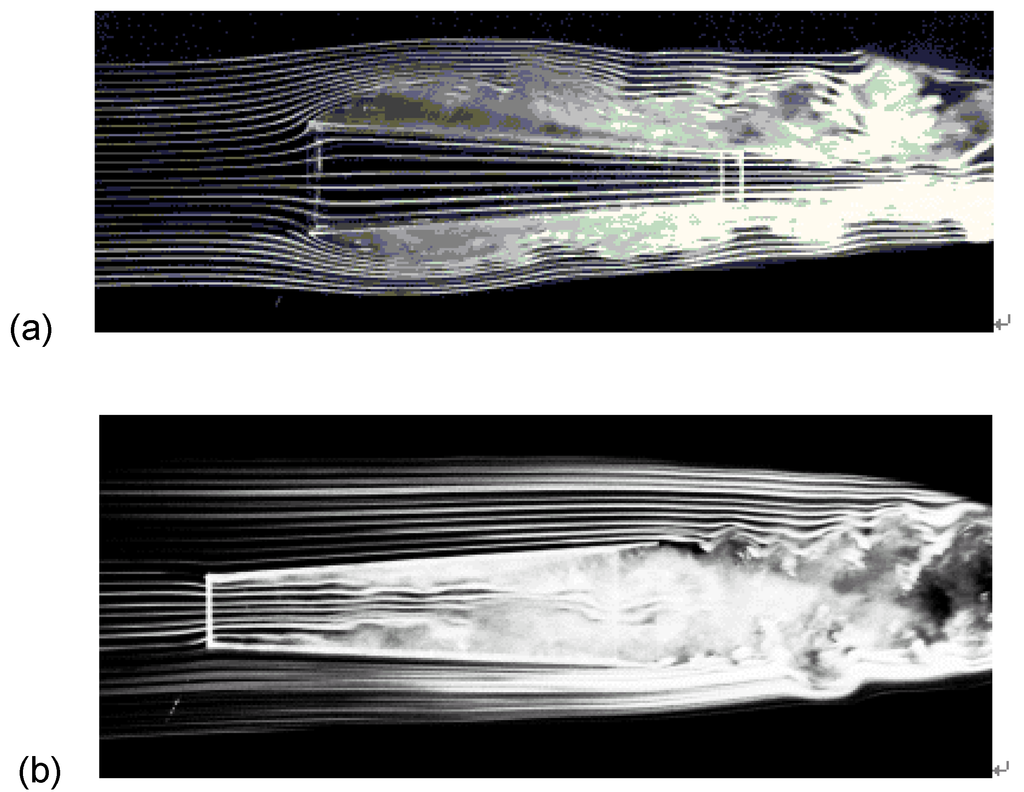
Figure 3.
Flows around nozzle- and diffuser-type models. L/D = 7.7. The smoke flows from left to right. (a) Nozzle-type model, (b) Diffuser-type model.
2.2. Idea of a Ring-Type Plate Which Forms Vortices (It is called “Brim”)
If we use a long type diffuser, the wind speed is accelerated further near the entrance of the diffuser. However, a long heavy structure is not preferable in the practical sense. Then we added a ring-type plate, called “brim”, to the exit periphery of a short diffuser. The plate forms vortices behind it and generates a low-pressure region behind the diffuser, as shown in Figure 4. Accordingly, the wind flows into a low-pressure region, the wind velocity is accelerated further near the entrance of the diffuser. Figure 5 illustrates the flow mechanism. A shrouded wind turbine equipped with a brimmed diffuser came into existence in this way. We call it the “wind-lens turbine”. Next we add an appropriate structure for entrance, called an inlet shroud, to the entrance of the diffuser with a brim. The inlet shroud makes wind easy to flow into the diffuser. Viewed as a whole, the collection-acceleration device consists of a venturi-shaped structure with a brim [8,9,10].
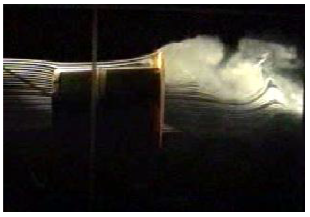
Figure 4.
Flow around a circular-diffuser model with a brim. The smoke flows from left to right. L/D = 1.5. The area ratio μ (outlet area/inlet area) of the circular-diffuser model is 1.44. Karman vortices are formed behind brim.
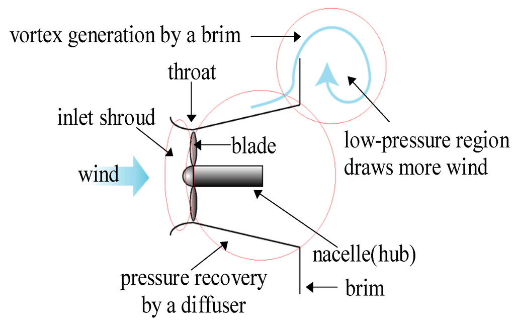
Figure 5.
Flow around a wind turbine with brimmed diffuser (wind-lens).
As for other parameters, we have examined the diffuser opening angle, the hub ratio, and the center-body length [10,11,12]. Then the optimal shape of a brimmed diffuser was found [10]. In addition, we are now examining the turbine blade shape in order to acquire higher output power. As illustrated in Figure 6, when a brimmed diffuser is applied (see also Figure 7), a remarkable increase in the output power coefficient (Cw=P/0.5ρAU3, P: output power, A: swept area of turbine blades) of approximately 4–5 times that of a conventional wind turbine is achieved in field experiment. A simple theory for the present wind-lens turbine was given by Inoue et al [13]. The output performance is decided by the two factors of the pressure discovery coefficient of the diffuser shroud and the base pressure behind it.
2.3. Characteristics of a Wind Turbine with Brimmed Diffuser Shroud
Figure 7 shows the first prototype of a wind turbine equipped with a brimmed diffuser shroud (rated power 500 W, rotor diameter of 0.7 m). The diffuser length of this model is 1.47 times as long as the diameter of the diffuser throat D (Lt = 1.47 D, for Lt, see Figure 8). The width of the brim is h = 0.5D. For the field experiment, some data are apparently significantly larger than the “wind tunnel-curve”; this is because the fluctuation in wind speed (variance component) in the field gives a higher value than the wind tunnel value at a constant wind speed. The important features of this wind turbine equipped with a brimmed diffuser shroud are as follows.
- (1)
- Four-fivefold increase in output power compared to conventional wind turbines due to concentration of the wind energy (“wind-lens” technology).
- (2)
- Brim-based yaw control: The brim at the exit of the diffuser makes wind turbines equipped with a brimmed diffuser rotate following the change in the wind direction, like a weathercock. As a result, the wind turbine automatically turns to face the wind.
- (3)
- Significant reduction in wind turbine noise: Basically, an airfoil section of the turbine blade, which gives the best performance in a low-tip speed ratio range, is chosen. Since the vortices generated from the blade tips are considerably suppressed through the interference with the boundary layer within the diffuser shroud, the aerodynamic noise is reduced substantially [14].
- (4)
- Improved safety: The wind turbine, rotating at a high speed, is shrouded by a structure and is also safe against damage from broken blades.
- (5)
- As for demerits, wind load to a wind turbine and structural weight are increased.
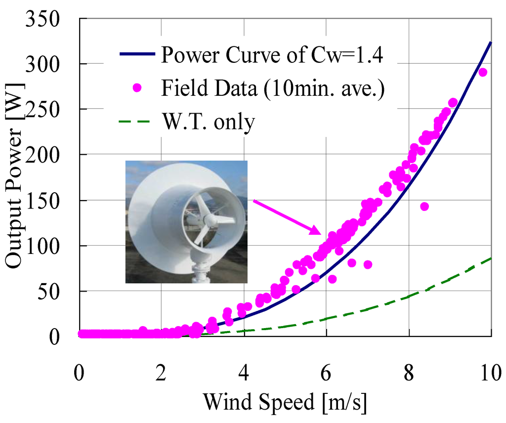
Figure 6.
Field experiment of 500 W wind turbine with wind-lens. Cw is the power coefficient.
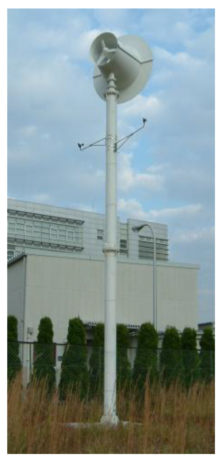
Figure 7.
500 W wind-lens turbine (rotor diameter 0.7 m).
3. Development of a Shrouded Wind Turbine with Compact Brimmed Diffuser
For the practical application to a small-size and mid-size wind turbine, we have been developing a compact-type brimmed diffuser. For the 500 W wind-lens turbine, the length of brimmed diffuser Lt is 1.47D and still relatively long as a collection-acceleration structure for wind (for Lt, see Figure 8). If we apply this brimmed diffuser to a larger wind turbine in size, the wind load to this structure and the weight of this structure becomes severe problems. Therefore, to overcome the above-mentioned problems, we propose a very compact collection-acceleration structure (compact brimmed diffuser), the length Lt of which is quite short compared to D, i.e., Lt < 0.4D. We made a couple of compact brimmed diffusers in a range of a relatively short one to a very short one of Lt = 0.1D – 0.4D. We conducted the output performance test of those wind-lens turbines with compact brimmed diffuser in a wind tunnel experiment and also carried out a field test using a prototype 5 kW type model.
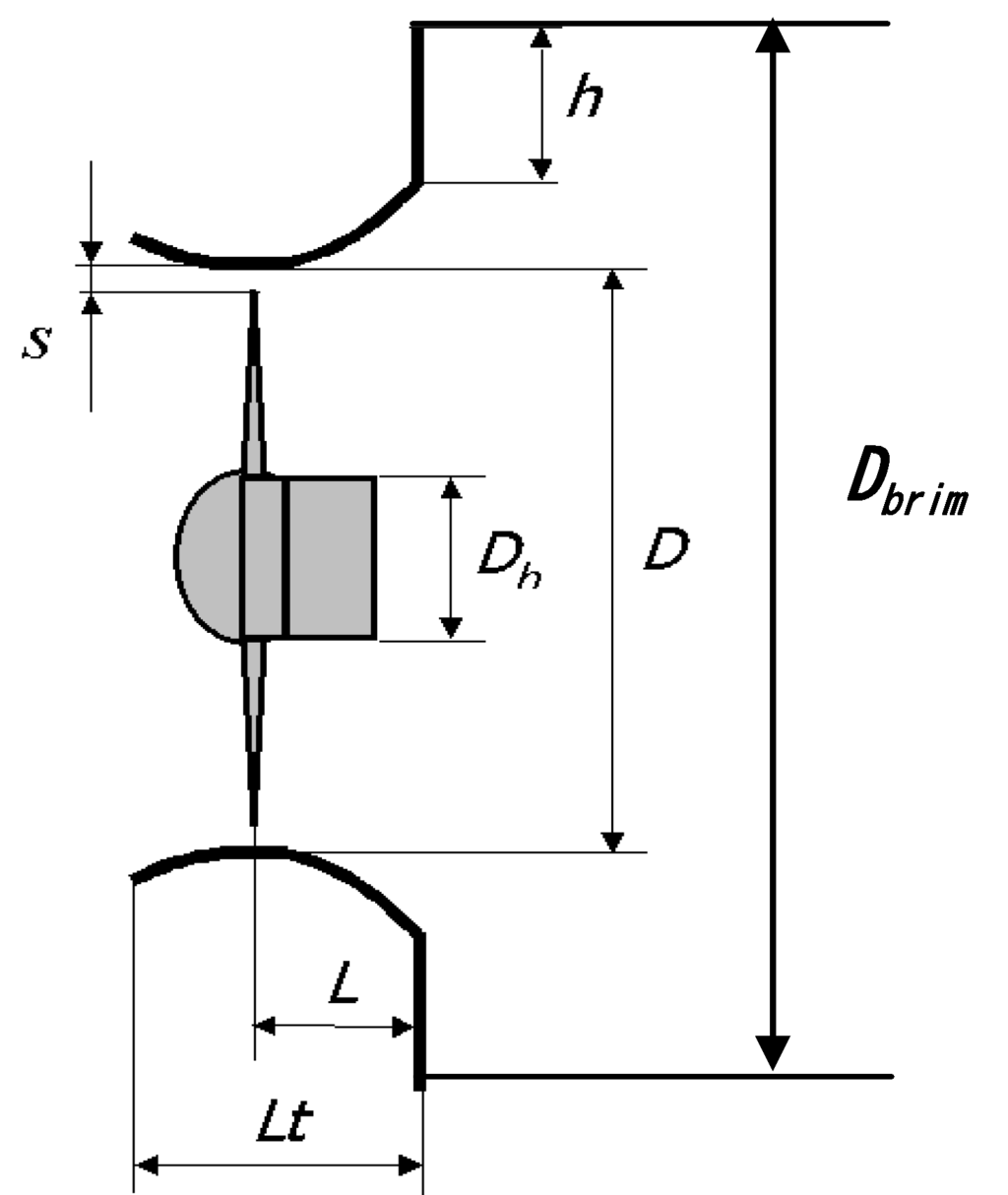
Figure 8.
Schematic of wind-lens turbine.
3.1. Experimental Method in Output Performance Test of Compact Wind-Lens Turbines
For the size of the brimmed diffuser in the present experiment, the throat diameter D is 1020 mm and the rotor diameter is 1000 mm. Figure 8 shows a schematic of a compact wind-lens turbine. We made four types of diffusers called A-, B-, C- and S-type with different sectional shapes, as shown in Figure 9. Table 1 shows the length ratios Lt /D and the area ratios μ of (exit area)/(throat area) for each diffuser model. All diffuser types show almost the same Lt /D, but show different area ratio μ. For the S-type diffuser, it has a straight sectional shape such as the 500 W prototype. For the other three types, A to C, curved sectional shapes are adopted, as shown in Figure 9. For C-type, we adopted a cycloid curve for the sectional shape. Here, the hub ratio Dh/D is 13% and the tip clearance s is 10 mm.
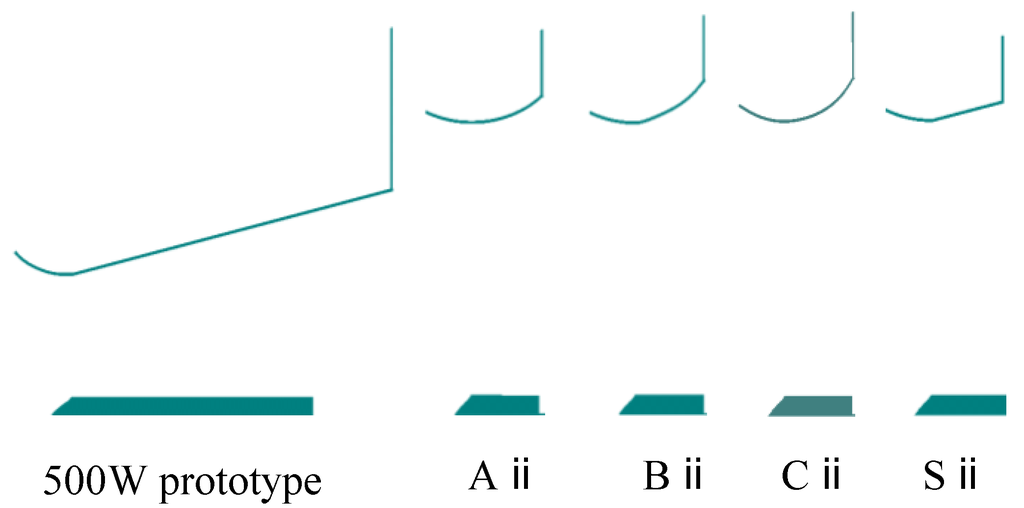
Figure 9.
Sectional shapes of wind-lens.

Table 1.
Parameters of wind-lens shapes
| Diffuser | Prototype | Aⅱ | Bⅱ | Cⅱ | Sⅱ |
|---|---|---|---|---|---|
| Lt/D | 1.470 | 0.225 | 0.221 | 0.221 | 0.225 |
| μ | 2.345 | 1.173 | 1.288 | 1.294 | 1.119 |
As for the experimental method, connecting a torque transducer (the rating 10 N∙m) to the wind turbine and in the rear of it, an AC torque motor brake, was set for the loading. We measured the torque Q(N∙m) and the rotational speed n (Hz) of the wind turbine in the condition that the turbine loading was gradually applied from zero. The calculated power output P(W) = Q × 2πn is shown as a performance curve. The shrouded wind turbine model with a compact brimmed diffuser was supported by a long straight bar from the measurement bed which was placed in the downstream and consists of a torque transducer, a revolution sensor and an AC torque motor brake, as shown in Figure 10. The approaching wind speed Uo was 8 m/s.
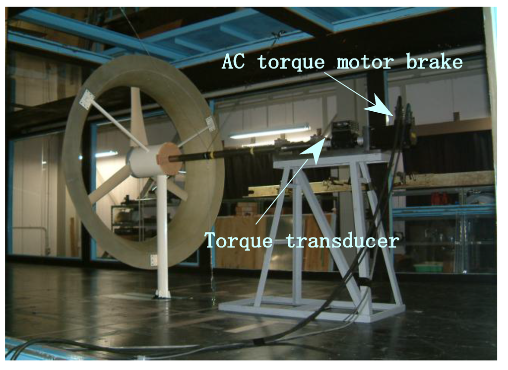
Figure 10.
Output performance test of a wind-lens turbine in a wind tunnel.
3.2. Selection of Compact Brimmed Diffuser Shape as Wind-Lens
Figure 11 shows the experimental result of the shrouded wind turbines with compact brimmed diffuser of Aii, Bii, Cii and Sii type. The height of brim is 10%, i.e., h = 0.1D. The horizontal axis shows the blade tip speed ratio λ = ωr/Uo, here ω is the angular frequency, 2πn, and r is the radius of a wind turbine rotor (r = 0.58 m). The vertical axis shows the power coefficient Cw (=P/(0.5ρU∞3A), A is the rotor swept area, πr2). The wind turbine blade with a specially designed wing-section contour was designed using a three-bladed wind turbine resulting in an optimum tip speed ratio of around 4.0. As shown in Figure 11, when a compact brimmed diffuser is applied, we have successfully achieved a remarkable increase in the output power coefficient approximately 1.9–2.4 times as large as a bare wind turbine. Namely, the Cw is 0.37 for a bare wind turbine, on the other hand, the Cw is 0.7–0.88 for a wind turbine with a compact brimmed diffuser. The experimental results shown in Figure 11 were obtained under the same wind speed and the swept area of a wind turbine.
First, we compare Aii type with Sii type in Figure 11. Both types have an almost same area ratio μ. The Cw of Aii is higher than Sii. It means that the curved sectional shape is preferable to the straight one. Furthermore, it is noted that the Bii and Cii types show higher Cw compared to Aii type. It means that if the boundary-layer flow along the inside wall of curved diffuser dose not show a large separation, Bii and Cii types, which have a larger area ratio μ compared to that of Aii, are suitable to a compact diffuser.
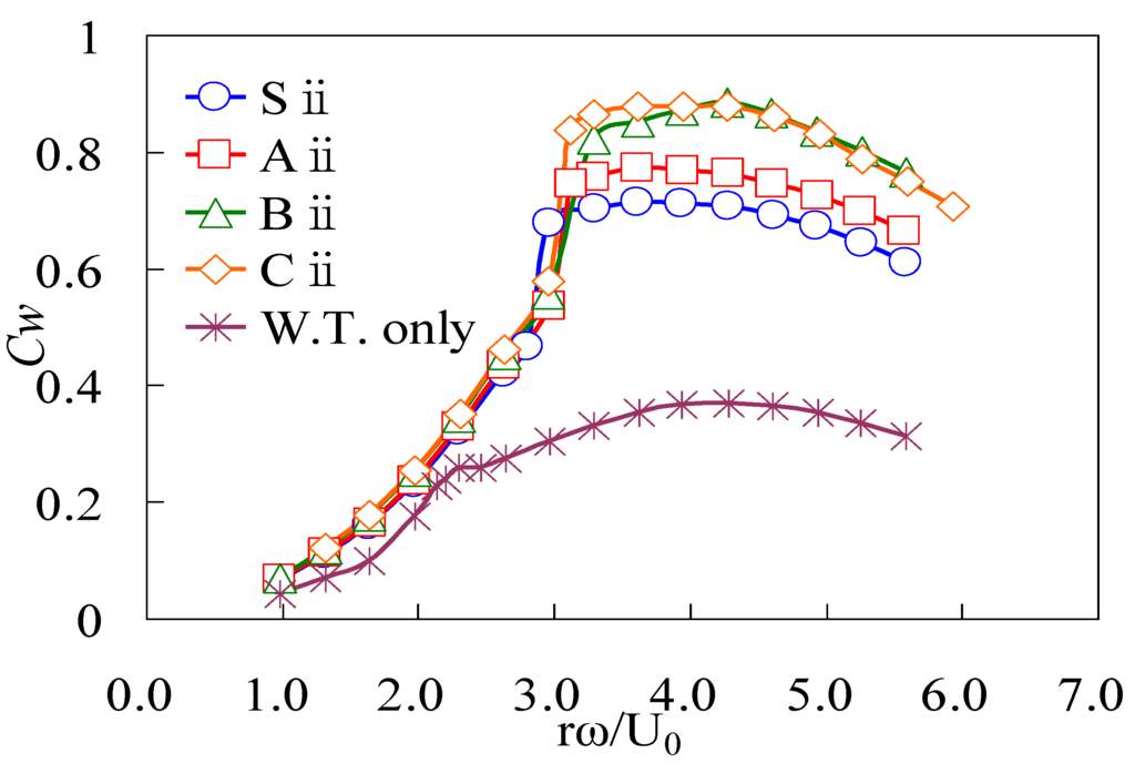
Figure 11.
Power coefficients Cw of various wind-lens turbines vs. tip-speed ratio λ = ωr/Uo. The brim height is 10%, i.e., h = 0.1D.
If we adopt the swept area A* instead of A (due to the rotor diameter), where A* is the circular area due to the brim diameter Dbrim at diffuser exit, the output coefficient Cw* based on A* becomes 0.48–0.54 for those compact wind-lens turbines. It is still larger than the power coefficient Cw (around 0.4) of conventional wind turbines. It means that the compact wind-lens turbines clearly show higher efficiency compared to conventional wind turbines, even if the rotor diameter of a conventional wind turbine is extended to the brim diameter.
3.3. Output Power of Wind-Lens Turbine with the Compact Diffuser Length
From the experimetal result shown in Figure 11, we discuss C-type diffuser as the compact collection-acceleration structure. For the next step, we investigated the length effect of the C-type diffuser on the output performance of wind-lens turbines. We prepared four kinds of C-type diffusers from C0 to Ciii, as described in Table 2. Figure 12 shows the result of output performance with the four C-type diffuser lengths. The brim height is 10%, i.e., h = 0.1D. Figure 13 also shows the variation of Cw,max with the diffuser length Lt /D, here Cw,max is the maximum value of Cw in the output performance curves as is shown in Figure 12. As expected, the Cw,max value becomes smaller as the diffuser length Lt /D becomes smaller. However, when the brim height is larger than 10%, i.e., in case of h > 0.1D, the Cw of a wind-lens turbine with C0-type diffuser shows almost two-fold increase compared to a bare wind turbine and the one with Ciii-type diffuser shows 2.6-times increase. Thus, we can expect a 2–3-times increase in output performance, even if we use a very compact brimmed diffuser as the wind-lens structure.
Table 2.
Parameters of C-type wind-lens. For C0–Ciii diffuser, see Figure 13.
| Diffuser | C0 | Cⅰ | Cⅱ | Cⅲ |
|---|---|---|---|---|
| Lt/D | 0.1 | 0.137 | 0.221 | 0.371 |
| μ | 1.138 | 1.193 | 1.294 | 1.555 |
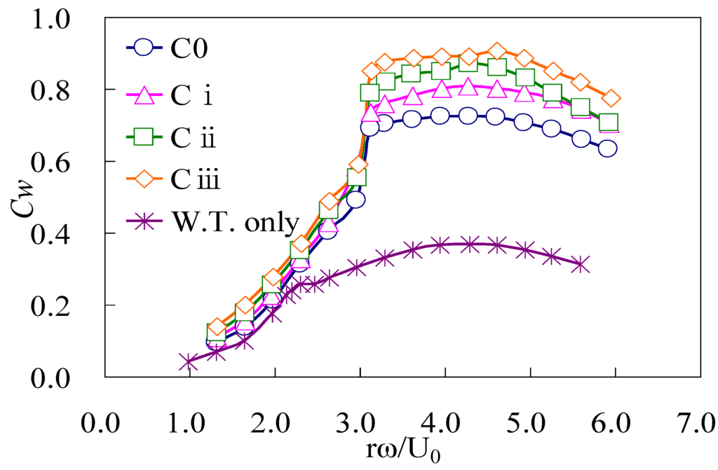
Figure 12.
Power coefficients Cw of wind-lens turbines with C-type wind-lens (h = 0.1D). For C0–Ciii diffuser, see Figure 13.
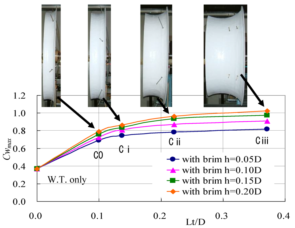
Figure 13.
Maximum power coefficient Cw,max versus C-type wind-lens length.
3.4. Field Experiment
As described above, one of the merits of wind-lens turbine is the brim-based yaw control. Namely, owing to the brim, the wind-lens turbine automatically turns to face the wind. However, for the comapct wind-lens structure, it is difficult to realize the wind-lens turbine as the upwind-type wind turbine. Therefore, we made a prototype compact wind-lens turbine as a downwind-type.
For the 5 kW downwind-type wind turbine, we selected the Cii-type diffuser (Lt /D = 0.22) as the wind-lens structure. The brim height is 10%, i.e., h = 0.1D. Here, D is 2560 mm and the rotor diameter is 2500 mm. Figure 14 shows the prototype 5 kW wind-lens turbine. We conducted a field experiment using this 5 kW wind turbine. Figure 15 shows the result of performance test on a windy day. The field data are plotted as 1 minute average data. The power curve is plotted along the Cw = 1.0 curve and the high output performance of the present wind-lens turbine is demonstrated. We obtained 2.5-times increase in output power as compared to conventional (bare) wind turbines, due to concentration of the wind energy. Adopting the reference area A*, where A* is the circular area due to the brim diameter Dbrim at diffuser exit, the output coefficient Cw* based on A* reaches 0.54 for the present compact wind-lens turbines.
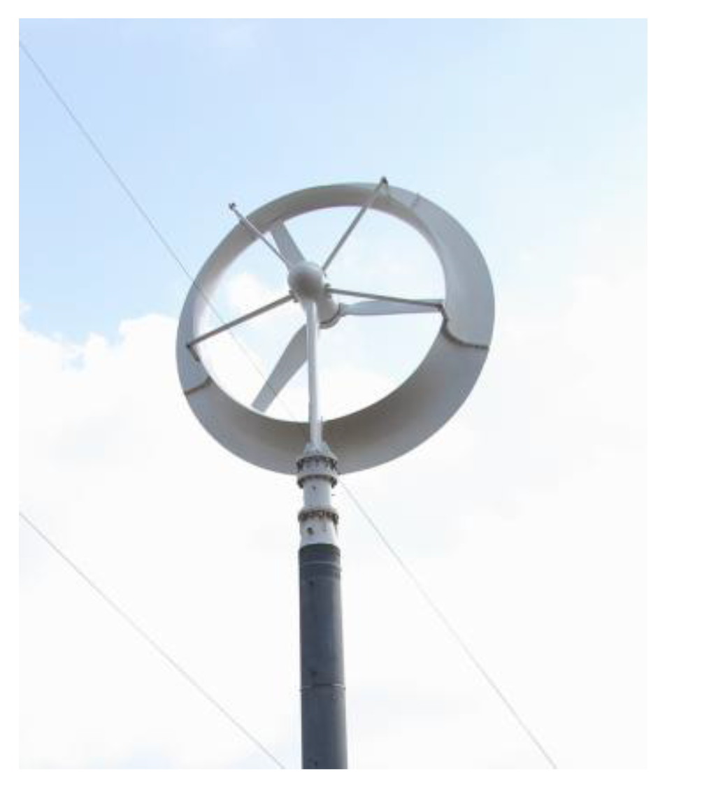
Figure 14.
5 kW wind-lens turbine (rotor diameter 2.5 m), downwind type
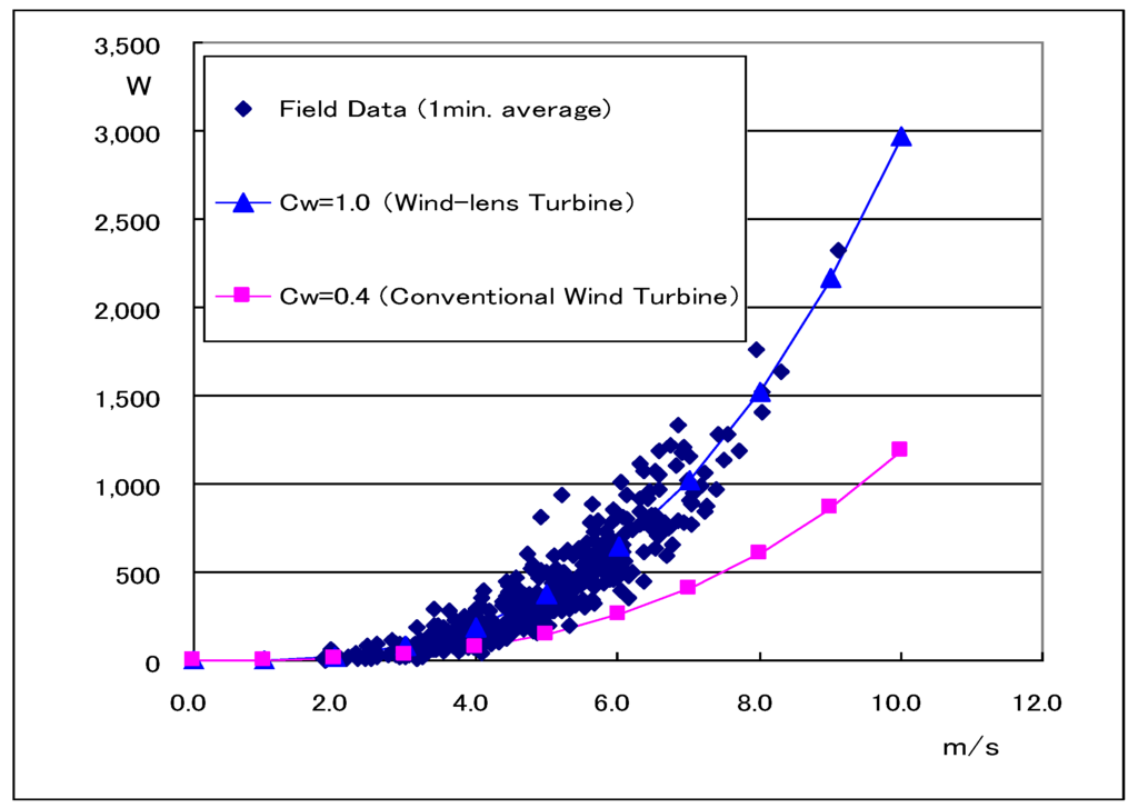
Figure 15.
Field experiment of 5 kW wind-lens turbine. Cw is the power coefficient. Cw* = 0.54, based on the brim diameter area.
4. Application of 5 kW Wind-Lens Turbines for Supplying Stable Electricity to an Irrigation Plant in China
Northwest China is an area facing deepening global environmental problems. To stop desertification and to turn the land into green land, irrigation and greenery projects began by capitalizing on the vast wind energy as a power source in the northwest, as shown in Figure 16. A small wind-lens turbine, which can be moved and installed easily, is the best means of power generation in this area without power grid infrastructure. The highly efficient wind-lens turbines offering the great small windmill performance, developed by the authors’ group, were improved, remodeled and enlarged through technological development for the application to a desert area. Six units of 5 kW wind-lens turbines were installed to build a wind farm for irrigation, and their effectiveness for the greenery project has been examined. Thus, a plant was constructed for pumping irrigation system by building a network of distributed power sources, ensuring that micro-grids will stably supply electric power by combining the network and power storage technology using batteries. This plant initiated to implement tree planting and greening the desert, and its effectiveness will be examined.
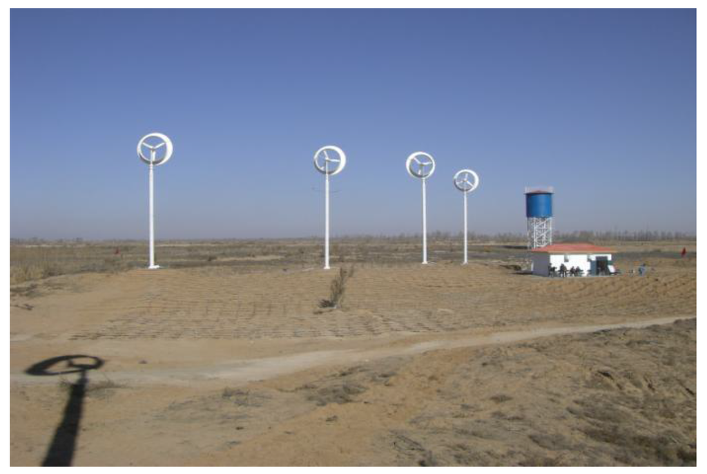
Figure 16.
An irrigation-greenery plant using wind energy (5 kW wind-lens turbine farm) in a desert area in northwest China.
5. Efficient Utilization of Wind Energy on the Seashore in an Urban City
Three 5 kW wind-lens turbines have been recently installed in a seashore park in Fukuoka city, Japan. Fukuoka city faces the sea in the north, as shown in Figure 17. Since relatively strong winds are often observed in the winter season, Fukuoka city and our Kyushu University planned to make a collaborative research to install small wind-lens turbines, examining the effectiveness as a distributed power plant. Figure 17 shows the seaside park where the wind-lens turbines were installed. North is located in the upper side in this figure. In parallel with field measurements using wind poles, to implement the micro-siting for wind turbines, we carried out a numerical simulation of wind pattern over this complex area using RIAM-COMPACT [15], which is a calculation code based on a LES turbulence model. We assume the northern prevailing wind, say, a sea breeze. Figure 18 shows the calculation domain, extending 2800 m in the north-south direction (x-direction), 3500 m in the east-west direction (y-direction) and 900 m in the vertical direction (z-direction). The inflow condition is 1/7 power law in the vertical direction. The number of grid points is 161 × 201 × 51. The grid resolution is Δx = Δy = 17.5 m in horizontal directions and Δzmin = 1 m in the vertical direction, concentrating towards the ground. The Reynolds number based on the highest building h in the calculation domain is Re = 10,000. Figure 19 shows the result of the wind pattern at a height of 15 m, which is the hub height of small wind-lens turbines. We can see the accelerated areas around the entrance of a river and decelerated areas due to the high buildings near the shoreline. Judging from this result, we selected a suitable site, which is near the entrance of the large river in the left-hand side of Figure 17. Thus, three 5 kW wind-lens turbines were installed, as seen in Figure 20.
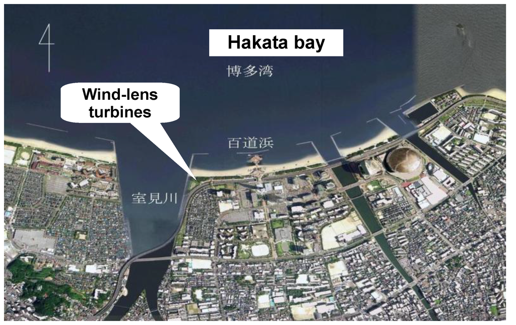
Figure 17.
Seashore in Fukuoka city, where a few rivers are seen.
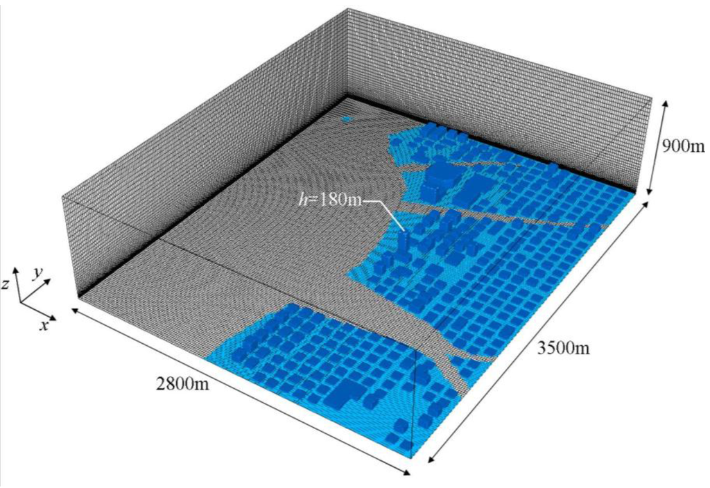
Figure 18.
Computational domain. Prevailing wind is from north along x-direction. The inflow condition is 1/7 power law. The number of grid points is 161 × 201 × 51. The grid resolution is Δx = Δy = 17.5 m in horizontal directions and Δzmin = 1 m in the vertical direction. The Reynolds number based on the highest building h is Re = 10,000 in the calculation.
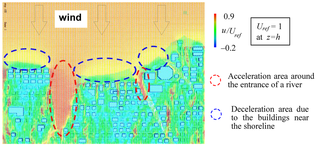
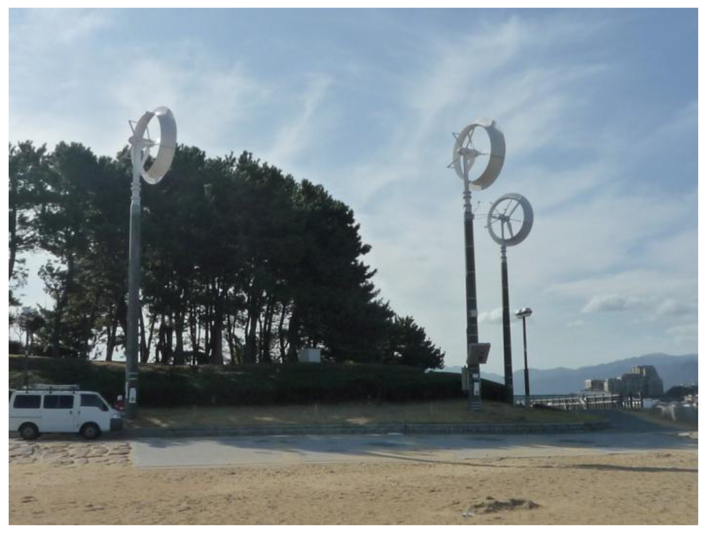
Figure 20.
5 kW Wind-lens turbines in a seashore park in Fukuoka city, Japan.
6. Conclusions
A collection-acceleration devise for wind, “the brimmed diffuser”, which shrouds a wind turbine, was developed. Significant increase in the output power of a micro-scale wind turbine was obtained. With a relatively long diffuser (Lt = 1.47D), a remarkable increase in the output power of approximately 4–5-times that of a conventional wind turbine is achieved. This is because a low-pressure region due to a strong vortex formation behind the broad brim draws more mass flow to the wind turbine inside the diffuser.
For the purpose of the practical application to a small- and mid-size wind turbine, we developed a very compact brimmed diffuser (wind-lens structure). Using this compact brimmed diffuser, we achieved two-three-fold increase in output power as compared to conventional (bare) wind turbines, due to concentration of the wind energy. We are now developing a wind-lens turbine of 100 kW at the rated wind speed of 12 m/s. The rotor diameter will be 12.8 m, which is much smaller than a conventinal wind turbine of the same rated power; two-thirds the size.
Incidentally, if we adopt the swept area A* instead of A (due to the rotor diameter), where A* is the circular area due to the brim diameter Dbrim at diffuser exit, the output coefficient Cw* based on A* becomes 0.48–0.54 for those compact wind-lens turbines. It is still larger than the power coefficient Cw (around 0.4) of conventional wind turbines. It means that the compact wind-lens turbines clearly show higher efficiency compared to conventional wind turbines, even if the rotor diameter of a conventional wind turbine is extended to the brim diameter.
For the examination of practical application, an international project and a local project using 5 kW wind-lens turbines were initiated. Six units of 5 kW wind-lens turbines were installed to build a wind farm for an irrigation plant in a desert area in northwest China, and their effectiveness for the greenery project has been examined. Three 5 kW wind-lens turbines have been recently installed in seashore in Fukuoka city, Japan, aiming at the efficient utilization of wind energy.
Acknowledgements
This work was supported by five organizations including a Grant-in-Aids for Scientific Research, No.14205139, sponsored by the Ministry of Education, Culture, Sports, Science and Technology, Japan, Environment Protection Research sponsored by the Sumitomo Fund, Fluid Machinery Research sponsored by the Harada Memorial Fund, and the Program and Project for Education and Research of Kyushu University. It was also supported by NEDO (New Energy Development Organization) of the Ministry of Economy, Trade and Industry. We gratefully acknowledge our laboratory staff, Messrs. N. Fukamachi and K. Watanabe, Research Institute for Applied Mechanics, Kyushu University, for their great cooperation in the experiments and data analysis.
References
- Lilley, G.M.; Rainbird, W.J. A Preliminary Report on the Design and Performance of Ducted Windmills; Report No. 102; College of Aeronautics: Cranfield, UK, 1956. [Google Scholar]
- Gilbert, B.L.; Oman, R.A.; Foreman, K.M. Fluid dynamics of diffuser-augmented wind turbines. J. Energy 1978, 2, 368–374. [Google Scholar] [CrossRef]
- Gilbert, B.L.; Foreman, K.M. Experiments with a diffuser-augmented model wind turbine. Trans. ASME, J. Energy Resour. Technol. 1983, 105, 46–53. [Google Scholar] [CrossRef]
- Igra, O. Research and development for shrouded wind turbines. Energ. Conv. Manage. 1981, 21, 13–48. [Google Scholar] [CrossRef]
- Phillips, D.G.; Richards, P.J.; Flay, R.G.J. CFD modelling and the development of the diffuser augmented wind turbine. In Proceedings of the Comp. Wind Engineer, Birmingham, UK, 2000; pp. 189–192.
- Phillips, D.G.; Flay, R.G.J.; Nash, T.A. Aerodynamic analysis and monitoring of the Vortec 7 diffuser augmented wind turbine. IPENZ Trans. 1999, 26, 3–19. [Google Scholar]
- Bet, F.; Grassmann, H. Upgrading conventional wind turbines. Renew. Energy 2003, 28, 71–78. [Google Scholar] [CrossRef]
- Ohya, Y.; Karasudani, T.; Sakurai, A. Development of high-performance wind turbine with a brimmed diffuser. J. Japan Soc. Aeronaut. Space Sci. 2002, 50, 477–482. (in Japanese). [Google Scholar]
- Ohya, Y.; Karasudani, T.; Sakurai, A. Development of high-performance wind turbine with a brimmed diffuser, Part 2. J. Japan Soc. Aeronaut. Space Sci. 2004, 52, 210–213. (in Japanese). [Google Scholar]
- Ohya, Y.; Karasudani, T.; Sakurai, A.; Abe, K.; Inoue, M. Development of a shrouded wind turbine with a flanged diffuser. J. Wind Eng. Ind. Aerodyn. 2008, 96, 524–539. [Google Scholar] [CrossRef]
- Abe, K.; Ohya, Y. An investigation of flow fields around flanged diffusers using CFD. J. Wind Eng. Ind. Aerodyn. 2004, 92, 315–330. [Google Scholar] [CrossRef]
- Abe, K.; Nishida, M.; Sakurai, A.; Ohya, Y.; Kihara, H.; Wada, E.; Sato, K. Experimental and numerical investigations of flow fields behind a small-type wind turbine with flanged diffuser. J. Wind Eng. Ind. Aerodyn. 2005, 93, 951–970. [Google Scholar] [CrossRef]
- Inoue, M.; Sakurai, A.; Ohya, Y. A simple theory of wind turbine with brimmed diffuser. Turbomach. Int. 2002, 30, 46–51. (in Japanese). [Google Scholar]
- Abe, K.; Kihara, H.; Sakurai, A.; Nishida, M.; Ohya, Y.; Wada, E.; Sato, K. An experimental study of tip-vortex structures behind a small wind turbine with a flanged diffuser. Wind Struct. 2006, 9, 413–417. [Google Scholar] [CrossRef]
- Uchida, T.; Ohya, Y. Micro-siting technique for wind turbine generators by using large-eddy simulation. J. Wind Eng. Ind. Aerodyn. 2008, 96, 2121–2138. [Google Scholar] [CrossRef]
© 2010 by the authors; licensee Molecular Diversity Preservation International, Basel, Switzerland. This article is an open-access article distributed under the terms and conditions of the Creative Commons Attribution license (http://creativecommons.org/licenses/by/3.0/).