
AC Distributed Winding with Low Higher Spatial Harmonics Content in Mmf Distribution


Department of Electrical Power Engineering, Power Electronics and Electrical Machines, Kielce University of Technology, Al. 1000-lecia P.P. 7, 25-314 Kielce, Poland
Energies 2023, 16(14), 5430; https://doi.org/10.3390/en16145430
Submission received: 22 June 2023
/
Revised: 14 July 2023
/
Accepted: 14 July 2023
/
Published: 17 July 2023
(This article belongs to the Special Issue Advances in the Field of Electrical Machines and Drives 2022)
Abstract
:This paper presents a new winding with a low higher spatial harmonics content. This winding enables the elimination of the fifth harmonic, as the most significant, in three-phase winding and the third harmonic in two-phase symmetrical winding. The suppression of higher spatial harmonics is particularly evident with the number of slots per pole per phase qs = 2. The winding factors for the higher spatial harmonics of the order ν = 6 k ± 1 in the case of three-phase winding, and ν = 4 k ± 1 in the case of two-phase winding, for k = 1, 3, 5, …, will be equal to zero. A two-phase measurement winding, with the number of slots per pole per phase qs = 1, was used to evaluate the higher spatial harmonics content in the magnetic field in the air gap of the machine. Experimental verification of the designed winding was carried out.
1. Introduction
The arrangement of winding in the slots of an electric machine causes a non-sinusoidal magnetomotive force distribution along the circumference of the machine. The magnetic field generated by mmf, in addition to the fundamental, also contains odd higher spatial harmonics. The higher spatial harmonics of the magnetic field induce currents of higher time harmonics in the rotor of the induction motor. As a result of the interaction of the higher harmonics of the magnetic field with the higher harmonic currents of the rotor, parasitic electromagnetic torques are generated [1,2]. In addition, the higher spatial harmonics of the stator mmf are a source of additional losses in the rotor of the squirrel-cage induction motor [3,4,5], with a consequent efficiency decrease in these machines.
In the case of synchronous machines, the non-sinusoidal distribution of the magnetic field of the excitation winding causes voltages of higher time harmonics to be induced in the phase windings of the armature, which cause distortions of the waveform of the fundamental of the phase voltage. Higher voltage harmonics cause the phase currents to be distorted as well. This has a negative impact, both on the operation of the synchronous machine itself, as well as on the operation of other electrical devices and the power supply network.
For these reasons, the armature phase winding of induction or synchronous machines should be characterised by a low higher spatial harmonics content, particularly of the low orders. To achieve this, the winding factors for higher harmonics should have small values. In practice, single-layer windings—typically in low-power motors—and double-layer windings are used [6,7,8,9]. In single-layer windings, the suppression of higher harmonics of the magnetic field is carried out by increasing the number of slots per pole per phase. This leads to an increase in the number of stator slots and, thus, a decrease in the tooth cross-section. This will cause an increase in the magnetic flux density in the stator teeth [8], resulting in an increase in the magnetising current and a decrease in the power factor. In double-layer windings, the suppression of higher harmonics of the lowest orders is possible by reducing the coil span relative to the diameter span [7,9]. In order to achieve complete elimination of a given harmonic, the absolute coil span measured in the slots must be an integer number, which is not always possible for design reasons.
The problem of eliminating higher spatial harmonics is considered in many publications. These works are mainly focused on fractional-slot concentrated windings [10,11,12,13], which are used in permanent magnet machines. The reduction of higher harmonics in an electrical machine with distributed windings is carried out by modifying the winding design [14,15,16], using varied slot pitches and different numbers of turns. This paper [17] presents the use of semi-magnetic wedges to close stator slots for the reduction of higher spatial harmonics in the magnetic field in the air gap of an induction motor.
A winding with a triangular distribution of linear turns density [18] over the span of the electrical angle 2π/m, where m is the number of stator or rotor phases, and hereafter referred to as a triangle winding, is also known in the literature. This winding is characterised by a low higher spatial harmonics content in the magnetomotive force distribution curve. However, the triangle winding does not allow for the complete elimination of higher harmonics of low orders, e.g., the fifth harmonic in the case of three-phase windings or the third harmonic in the case of two-phase windings. The modification of the triangle winding, the design of which has been patented [19], allows the elimination of any harmonic and a significant reduction of other higher harmonics.
This paper reviews the windings used in induction and synchronous machines with an integer number of slots per pole per phase. A method of analytically calculating the total winding factor for higher harmonics is presented. Particular focus has been placed on the modified triangle winding. For this winding, a method of selecting the winding design parameters to eliminate higher spatial harmonics is given. This winding has particularly good properties for the number of slots per pole per phase qs = 2. The winding parameters can then be chosen so that the winding factors for the spatial harmonics of the order ν = 6 k ± 1 in the case of three-phase winding, and ν = 4 k ± 1 in the case of two-phase winding, for k = 1, 3, 5, …, will be equal to zero. Experimental tests of the designed modified triangle winding were carried out. In order to investigate the contribution of higher spatial harmonics to the magnetic field in the air gap of a permanent magnet synchronous machine, a two-phase measurement winding was used, located in the stator slots, with the number of slots per pole per phase qs = 1.
2. Three-Phase Single-Layer Winding
Single-layer winding is a distributed winding placed in the slots of the stator core. The sides of the individual coils occupy the entire surface of the slot and are arranged in a single layer (Figure 1). The average span of the sides of one coil of a single-layer winding is equal to the pole pitch.
The individual coils are shifted relative to each other by an electrical angle αQs, corresponding to the slot pitch of the stator τs.
where p is the number of pole pairs, and Qs is the number of stator slots.
An analysis of the electromagnetic properties of the winding can be carried out on the basis of the linear current density distribution (Figure 1) of the winding.
The distribution of the linear current density of a single coil, depending on the circumferential coordinate φs, is a periodic function and can be represented as a Fourier series [18,20].
where Jc is the linear current density over the slot width, αs is the electrical angle corresponding to the slot width bs, and kbsν is the slot opening factor for the ν-th harmonic [6,18,20], with
where Nc is the number of turns in the slot; bs is the slot width; ic and is are the coil current and stator phase current; and ag is the number of parallel branches.
The resultant distribution of the linear current density generated by the qs coils of the group of one phase of the winding is equal to the sum of the distributions of the individual coils described by the function (2) and shifted with respect to each other by the electrical angle αQs. By writing down the resultant distribution of the linear current density in the axis of symmetry of the group of qs coils, the relationship for the distribution of the linear current density of one phase of the winding is obtained [18,20]
where Ns is the number of series windings of one phase of the stator winding, rs is the inner radius of the stator core, and kwsν is the total single-layer winding factor, with
where kdsν is the coil group distribution factor for the ν-th harmonic [6,7], with
where ms is the number of phases, and qs is the number of slots per pole per phase.
Knowing the linear current density distribution (6), the winding magnetomotive force of one phase is calculated from the relationships [20,21]:
The magnetic axes of the windings of phases b and c are shifted relative to phase a along the circumference by an electrical angle of 2/3π and 4/3π, respectively. Therefore, the resultant magnetomotive force distribution of the three-phase winding will be equal to the sum of the magnetomotive force distributions of the individual phases shifted relative to each other in space by an angle of 2/3π [21].
In an electric machine with a uniform air gap along the circumference of the machine, neglecting the magnetic voltages in the core, the flux density distribution at no-load is proportional to the magnetomotive force distribution.
Taking into account relationships (10) and (11), the magnetic flux density distribution along the circumference of the machine will be described by the relationship:
The magnetic flux density distribution should be a sinusoidal distribution. Therefore, the winding factor (7) for the higher harmonics in relationship (12) should have small values.
3. Three-Phase Double-Layer Winding
Double-layer winding (Figure 2) is characterised by the fact that the stator slots contain two sides of different coils placed in two layers, bottom and top. Double-layer winding with a shortened pitch can be treated as two single-layer windings with a diameter span and the number of turns in the coil Nc/2, shifted relative to each other by (msqs − Ys) slots or by the electrical angle βQs = (1 − ys)π radians, where Ys is the absolute coil span determined by the slot pitch number. Whereas ys is the relative coil span and is
where τp = Qs/(2p) is the pole pitch (the number of stator slots per pole).
The resultant distribution of the linear current density of double-layer winding will be the sum of the distributions of two single-layer windings shifted relative to each other by the electrical angle αQs and will be determined by relationship (6), with the total winding factor ν-th harmonic defined by the following formula:
where kbsν is the slot opening factor for the ν-th harmonic, kdsν is the distribution factor, and kpsν is the pitch factor [6,7] for the v-th harmonic, with
where ys is the relative coil span of the winding.
The value of the relative coil span of the winding ys is chosen to eliminate the specific spatial harmonic, i.e., the pitch factor (15) for this harmonic should be equal to zero. Odd harmonics of the lowest orders are eliminated, i.e., the fifth and seventh in three-phase windings and the third harmonic in two-phase windings. In order to better use the winding, the relative coil span of the winding ys should be close to unity [7,9]. For the odd ν relative coil span of the winding, ys is given by the formula (16).
4. Three-Phase Triangle Winding
A diagram of the three-phase triangle winding and the arrangement of the coil sides in the individual slots is shown in Figure 3a. This winding is characterised by a triangular distribution of turns, forming an isosceles triangle whose base contains 2qs − 1 slots. However, the height of this triangle, i.e., the highest number of turns on the side of the coil, is Nc. On the first side of the coil, the number of turns is Nc/qs (slot 3 in Figure 3a). The number of turns in the subsequent sides of the coil increases kNc/qs times, with k = 2, 3,..., qs, reaching a maximum value of Nc on side qs (slot 5).
The linear current density distribution of one phase of a triangle winding (Figure 3b) can be determined as a superposition of the linear current density qs of single-layer windings with the number of slots per pole per phase qs and the number of Nc/qs turns in the coil (Figure 3c–e), shifted relative to each other by the electrical angle αQs. By using a common coordinate system located in the symmetry axis of the winding of a given phase, the resultant distribution of the linear current density will be determined by relationship (6), with the winding factor for the v-th harmonic determined from the relationship [18].
The total winding factor is also influenced by the skew of the slots relative to the machine axis, which is taken into account by introducing a skewing factor [6,7,9] for the v-th harmonic.
where αsq is the electrical angle corresponding to the skew of the bsq slots relative to the machine axis, and αQs is the electrical angle corresponding to the stator slot pitch τs.
5. Modified Triangle Winding
5.1. Three-Phase Winding
The advantage of double-layer winding over triangle winding is that it allows the reduction of ν-th spatial harmonics in the magnetic field generated by the stator winding. By selecting from Equation (16) the appropriate relative coil span ys in two-layer winding, any spatial harmonic of the resultant stator magnetomotive force can be eliminated (the most significant harmonics of the lowest orders, typically the fifth or seventh, are eliminated). In order to achieve the complete elimination of a given spatial harmonic, the absolute span Ys, measured in the slots, must be an integer number, which is not always possible for design reasons. Eliminating spatial harmonics is also possible in a triangle winding suitably modified (Figure 3) by reducing the number of turns in the coil with the maximum number of turns (slots 5 and 14 in Figure 3). Then, the number of turns in the individual 2qs−1 coil sides of a given phase group, on the span of the electrical angle 2π/ms, is determined from the following relationship:
where h is the number of turns reduction factor, with 0 < h < 1.
The modified triangle winding must meet the following conditions:
- The number of turns in the slot must be an integer divisible by qs;
- The number of turns in the coil in which the reduction of turns has been made Nh = hNc must be an integer.
Considering the expression for the sum of the series [22]
Then, the number of turns in a group comprising 2qs − 1 coils is
For a triangle winding, the reduction factor h = 1 and the number of turns in the group is qsNc, which is the same as in a single-layer winding. For the modified triangle winding, as for some other windings (e.g., fractional-slot windings [23]), general formulae for the total winding factor cannot be derived. In such cases, the total winding factor is calculated by summing up the induced voltages (emf) in the coil sides of a suitably selected part of the winding. For this purpose, it is assumed that the emf of the ν-th spatial harmonic in the coil side is proportional to the number of turns in the coil. If the winding consists of identical coil groups but not necessarily with an equal number of turns in the individual coils of the group, the calculation of the winding factor can be limited to one group. If the coil groups are different, the winding factor calculation should be carried out for repeated winding cycles [9].
The total winding factor for the ν-th harmonic can be calculated from the star of the slot voltages phasors of the ν-th harmonic induced in the sides of the coils placed in the stator slots. For this purpose, the following parameters should be calculated [6,7,24]:
- The phase angle, i.e., the electrical angle between the emf of the ν-th harmonic of the sides in adjacent slots:
- The greatest common divisor (g.c.d) of the numbers QS and νp:
- The number of star radii:
- The angle between the radii of the star of slot voltages phasors:
The determination of the winding factor will be shown in the example of the three-phase modified triangle winding shown in Figure 4, with Qs = 18, p = 1, ms = 3, and qs = 3. Calculated from the above relationships, the phase angles and number of star radii are:
- For the first harmonic:
αQs1 = 2π/18= 20°, t = 1, S = 18, α’Qs1 =20°
- For the third harmonic:
αQs3 = 60°, t = 3, S = 6, α’Qs =60°.
By taking the coordinate system in the axis of symmetry of the linear current density, i.e., in the axis of symmetry of the winding phase (Figure 5), the star of the slot voltage phasors (Figure 5a) and the voltage polygon for the first harmonic (Figure 5c) are constructed. In a similar manner, a star of the slot voltage phasors (Figure 5b) and a voltage polygon for the third harmonic (Figure 5d) are obtained.
The phase angles β1, β2, …, β5 in Figure 4 and Figure 5 denote the electrical angles of the voltages of the sides of the coils placed in the slots with respect to the axis of symmetry of the phase winding. These angles for the considered phase winding a for the first harmonic are β1 = 50°, β2 = 70°, β3 = 90°, β4 = 110°, and β5 = 110°.
The winding factor of the ν-th harmonic is equal to the ratio of the sum of the voltage phasors Eνk of the coil sides to the algebraic sum of these voltages for the smallest part of the winding, whose winding factor characterises the whole winding [6,7,9,24].
where nb is the number of the sides of the coils of the winding part under consideration.
The amplitudes of the slot voltages induced in the individual coil sides are proportional to the number of coils Nk and are shifted in phase relative to each other by the angle αQν and relative to the winding symmetry axis by the phase angle βνk. From the voltage polygon (Figure 5), it follows that, for the assumed coordinate system, the relationship (26) can take the following form:
where Nk is the number of turns in the k-th coil side, βk is the electrical phase-shift angle of the k-th coil side relative to the axis of symmetry of the winding, and Nb is the number of turns of the part of the winding under consideration.
The position angles of the coil sides in the stator slots βk, k= 1,2,…, nb, relative to the axis of symmetry of the winding, can be expressed by coil spans Yk, k = 1,2, …, nb (Figure 4).
where Yk is the absolute coil span, yk is the relative coil span, and τp is the stator pole pitch.
Taking into account relationships (28) and (15), expression (27) for the total winding factor of the k-th harmonic will be a function of the span factor kpsν of the individual coils treated as concentric coils of different spans:
where kpsνk is the span factor of the k-th coil for the ν-th harmonic.
Windings with coils of identical spans can be treated as equivalent to windings with concentric coils since the directions of the currents in the coil sides in the same slots for both solutions do not change. The distribution of the linear current density for both cases will be the same. For the considered triangle winding shown in Figure 4, the total winding factor will be determined by the following relationship:
The numbers of turns on the individual coil sides are N1 = Nc/3, N2 = 2Nc/3, N3 = hNc, N4 = N2, and N5 = N1. Moreover, considering that for the odd harmonics that the trigonometric relationships apply, such as sinνβ5 = sinν(π − β1) = sinνβ1, sinνβ4 = sinν(π − β4) = sinνβ2, and β3= π/2, the expression for the winding factor of the ν-th harmonic will take the form of:
In order to calculate the reduction factor h, which ensures the elimination of the k-th harmonic, the numerator of expression (31) should be equated to zero. Hence,
By eliminating the fifth harmonic as the most significant one, after substituting the values ν = 5, y1= 5/9, and y2 = 7/9 into formula (32), the value of the reduction factor h = 0.85799265 is obtained. By substituting this value into relationship (31), the value of the total winding factor for the first and higher harmonics is obtained. Assuming that the value of reduction factor h = 1 in formula (31), the values of the total winding factor for triangle winding can be calculated. The values of the total winding factor are presented in Table 1.
The total winding factor is calculated from formula (27) for nb = 3
Taking into account that the number of turns in the individual coil sides of the windings considered are N1 = Nc/2, N2 = hNc, and N3 =N1, and considering that for the odd harmonics that the following relationships apply: sinνβ3 = sinν(π − β1) = sinνβ1, β2 = π/2; the expression (33) will take the form of:
Equating the numerator of expression (34) to zero, the value of the reduction factor h for the ν-th odd harmonic is
Taking into account that the electrical angle β1 for the relative span of the first coil y1 = Y1/τp = 4/6 is equal to β1 = y1π/2 = π/3, the reduction factor h for higher odd harmonics, except for the harmonics divisible by 3 and the slot harmonics of the order νQ = 6qsk ± 1 (k = 1, 2, …,), will have the value h = √3/2 = 0.866. Substituting this value for the reduction factor h into formula (34), the winding factor value for the fundamental is
The winding factor kwsν for the remaining harmonics, with the exception of the harmonics divisible by 3 and slot harmonics of the order νQ = 2msqsk ± 1 equals zero, which is a valuable advantage of the modified triangle winding, in the case of the number of slots per pole per phase qs = 2. The values of the total winding factor for the triangle winding modified for qs = 2 are presented in Table 1.
The winding factors, calculated on the basis of the star of slot voltage phasors according to relationship (27), should be multiplied by the slot opening factor (4).
Figure 7a presents the distribution of the linear current density of one phase of three-phase triangle winding, modified for qs, calculated from relationship (6) in Matlab. The calculated linear current density distribution accurately approximates the actual discrete distribution, for which the amplitudes of the linear current density along the slot width of the individual coil sides are Jc1 = 15 kA/m, Jc2 = 30 kA/m, and Jc3 = 38.6 kA/m for a reduction factor of h = 0.858. This proves the correctness of the calculated winding factors for the higher harmonics, both with regard to amplitude and the fact that their values are positive or negative. Figure 7b presents the magnetic flux density distribution generated by the three-phase magnetomotive force of the induction motor stator winding at no-load. This distribution contains only the first harmonic and the slot harmonics, whose amplitudes are approximately 5% of the amplitude of the fundamental. By applying a reduction factor of h = 0.858, the fifth harmonic is eliminated, and the amplitude of the seventh harmonic is approximately 0.1% of the first harmonic. The magnetic field generated by the three-phase stator winding does not contain a third harmonic. The use of the skew of the slots will result in the magnetic flux density distribution in the air gap being a sinusoidal distribution.
5.2. Two-Phase Winding
In two-phase windings, the two phases of the winding shift in space relative to each other by an electrical angle of 90°. These windings are used in electric micromachines, automation devices, and common-use single-phase induction motors. Single-layer windings are usually used in these motors. The magnetic field produced by the two-phase winding contains, in addition to the fundamental, higher spatial harmonics. The lowest-order harmonics are of the greatest importance, with the third harmonic being particularly important. It is possible to suppress the higher harmonics by using double-layer windings using shortened span coils. In order to eliminate, for example, the third harmonic, as the most significant one, the coil span should be equal to 2/3 of the pole pitch, i.e., Y = 2/3τp. Then, the pitch factor will be equal.
However, then the harmonics ν = 6k ± 1 (k = 1, 2, 3,…,) = 5, 7, 11, …, will not be weakened because the pitch factor for these harmonics is equal.
For instance, the pitch factor for the harmonics ν = 5, 7, 11, …, is the same as for the fundamental.
Therefore, a coil span other than 2/3τp is chosen for the two-phase double-layer windings. Thus, for the two-phase double-layer windings, a coil span of Y = 3/4τp is used for qs = 2, and Y = 5/6τp is used for qs = 3. A reduction of higher spatial harmonics in two-phase windings is also possible through the use of modified triangle windings.
Figure 8 presents a diagram of a two-phase modified triangle winding with Qs = 12, p = 1, qs = 3, ms = 2, and τp = 6. The electrical angle for the fundamental between the adjacent slots for this winding is αQ = p⋅360/Qs = 30°, while the position angles of the coil sides (Figure 8), with respect to the axis of symmetry of the winding of a given phase, are β1 = 30°, β2 = 60°, β3 = 90°, β4 = 120°, and β5 = 150°.
By substituting the above values into equation (32), the value of the reduction factor h = 2/3 = 0.6666 is obtained for the elimination of the third harmonic, ν = 3. The values of the winding factor kwν of two-phase winding for the higher harmonics, calculated from Equation (31), for reduction factor h = 2/3 and qs = 3, are presented in Table 2. Figure 9 shows a diagram of a two-phase modified triangle winding with Qs = 16, p = 2, qs = 2, ms = 2, and τp = 4.
Taking into account that the electrical angle β1 for the coil span Y1 = 2 and pole pitch τp = 4 (Figure 9 is equal to β1 = π/4, the reduction factor for the ν-th harmonics (except for slot harmonics) for qs = 2), according to formula (35), is equal to h = √2/2 = 0.7071. By substituting this value into Equation (34), the relationship for the total winding factor is obtained, for a two-phase winding, for the fundamental ν = 1 and qs = 2.
The winding factor for the third and higher harmonics, with the exception of the slot harmonics of order νQ = 4qsk ± 1 (k = 1, 2, 3, …,) = 7, 9, 15, …, is zero, which is the advantage of this winding for qs = 2. The values of the winding factors are presented in Table 2.
6. Experimental Section
This research subject is a permanent magnet synchronous generator, the structural diagram of which is presented in Figure 10.
Cylindrical permanent grade NH38 neodymium magnets, with a thickness of 3 mm and an angular span of 64, were glued to the surface of the solid steel rotor. The magnetisation direction of the permanent magnets is diametric. In order to reduce the higher slot harmonics in the stator phase voltage, the skew of the stator slots was used. Three-phase modified triangle windings, U1-U2, V1-V2, and W1-W2, and two-phase measurement windings, X1-X2 and Z1-Z2, were placed in the slots of the stator. The diagram of the three-phase modified triangle winding is presented in Figure 11. The number of turns in the slots of the stator, where the coil sides of different phases are placed (e.g., slots 1 and 3), is Nc = 194. The number of turns in the slots where the sides of the same phase coils are located (e.g., slots 2, 8) is Nc = 168. For these values of the number of turns, the reduction factor is h = 0.866, which ensures the elimination of higher harmonics of the order ν = 3qsk ± 1, where k = 1, 3, 5…, with the exception of the slot harmonics and harmonics divisible by 3.
Figure 12 shows a diagram of a two-phase measurement winding. The two phases of this winding are shifted relative to each other by an electrical angle of 90°.
The number of slots per pole per phase of this winding is qs = 1. The winding factor for qs = 1 for all higher spatial harmonics is 1. This allows the contribution of higher harmonics to the magnetic field in the air gap to be assessed. Since this winding is placed in skewed slots, this voltage is damped by the skewing factor.
The magnetic field in the air gap, generated by permanent magnets, is a non-sinusoidal field and, in addition to the fundamental component of the magnetic flux density, also contains higher harmonics. Magnetic field distribution calculations were carried out in FEMM 4.2 [25]. Figure 13a shows the distribution of the normal component of the magnetic flux density in the air gap along the circumference of the machine when the synchronous generator is at no-load, and Figure 13b shows the amplitude spectrum of the magnetic flux density. In the magnetic flux density amplitude spectrum, in addition to the fundamental, the harmonics of orders of ν = 3, 5, 7, and 19 and the slot harmonics of the orders νQ = 11, 23, 25, 35, and 37 are dominant.
During the rotation of the rotor, the non-sinusoidal magnetic field, created by the permanent magnets, will induce the voltage of the fundamental and higher harmonics in the phase windings of the stator and in the measurement windings. The content of higher harmonic voltages induced in the stator windings Esν in relationship to the voltages of the fundamental Es1 is determined by the relationship [26].
where kwsν and kws1 are the winding factors for the ν-th and first harmonic, respectively, ksqν and ksq1 are the skewing factors for the ν-th and first harmonic, respectively, and Bδν and Bδ1 are the magnetic flux densities for the ν-th and first harmonic, respectively.
Figure 14 shows the recorded waveforms of the voltages ea and eb, induced in the measurement windings placed in skewed stator slots and shifted by a 90° electrical angle with respect to each other. Since the number of slots per pole per phase qs of this winding equals 1, the winding factors for the higher harmonics kwsν are equal to the winding factor for the first harmonic kws1 and are kwsν = kws1 = 1. Therefore, according to Equation (36), the voltages of the higher harmonics in the measurement windings will be suppressed only by applying the skew of the stator slots αsq = π/6. The values of the skewing factor ksqν for the individual harmonics are ksq1 = 0.9886, ksq3 = 0.9003, ksq5 = 0.7379, ksq7 = 0.5271, ksq9 = 0.3001, ksq11 = 0.0899, ksq13 = −0.07605, and ksq15 = −0.18006.
Figure 14c,d show that the waveforms of the voltages induced in the measurement windings are dominated by higher harmonics of the orders ν = 3, 5, 7, and 9. These harmonics are poorly suppressed as a result of the skew of the stator slots. This causes the voltage trajectory ea = f(eb) (Figure 14b) to deviate from the circular shape.
Figure 15a shows the waveforms of the phase voltages ua and ub induced in the three-phase stator winding, and Figure 15b shows the amplitude spectrum of these voltages. These voltages mainly contain the third harmonic, whose winding factor and skewing factor are kws3 = 0.4641 and ksq3 = 0.9000, respectively; in order to eliminate the third harmonic, a different permanent magnet span must be chosen. As a result of using modified triangle winding and stator slot skewness (skewness by one slot pitch, αsq = π/6), the contribution of the other harmonics to the phase voltage waveforms (relationship 36) is negligible. The winding factors for the harmonics of order ν = 6k ± 1 (k = 1, 3, 5, …,) for qs = 2 (Table 1) are equal to zero. The skewing factors for the slot harmonics of order νQ = 11, 13, 23, 25, 35, 37, … are ksq11 = 0.08987, ksq13 = −0.07605, ksq23 = −0.04298, ksq25 = −0.03954, ksq35 = 0.02825, and ksq37 = −0.02672.
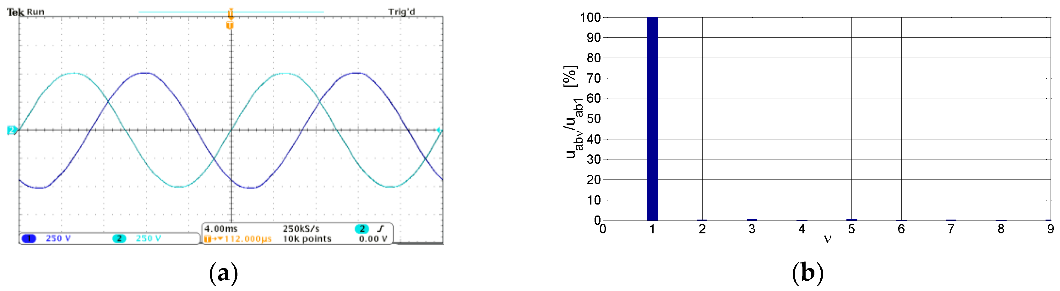
The waveforms of the line-to-line voltages uab and ubc and the amplitude spectrum of these voltages are presented in Figure 16. These voltages are sinusoidal and do not contain higher harmonics, as the third harmonic voltages are in phase and disappear in the line-to-line voltages.
7. Conclusions
The modified triangle winding described in this paper enables the higher spatial harmonics to be significantly reduced. It allows the elimination of the most significant harmonics, the fifth harmonic in three-phase winding and the third harmonic in two-phase winding. This phenomenon is beneficial, as the higher spatial harmonics of the magnetic field are the cause of parasitic torques and noise in the machine. They are a source of additional losses in squirrel-cage induction motors, with a consequent reduction in machine efficiency. The presented modified triangle winding can be used in the production of squirrel-cage induction motors with increased efficiency. The use of modified triangle windings in synchronous machines also results in the elimination of higher harmonic voltages induced in the phase windings. Modified triangle winding has particularly good electromagnetic properties for the number of slots per pole per phase qs = 2. It is then possible to select the winding parameters so that the winding factors for higher spatial harmonics, in addition to the slot harmonics and harmonics divisible by 3 in three-phase windings, are zero. By placing the two-phase measurement winding in the machine’s slots, with the number of slots per pole per phase qs = 1, the content of higher harmonics in the magnetic field in the air gap can be evaluated. The advantage of this winding design is its ease of fabrication, without the need to modify the magnetic core of the machine. The use of the proposed winding will not result in a significant increase in the cost of the motor compared to conventional winding (single-layer winding). For example, in the case of a 4 kW/1450 rpm induction motor, the cost of the motor will increase by approximately 0.5% due to the lower winding factor for the fundamental harmonic.
Funding
This research received no external funding.
Data Availability Statement
Not applicable.
Conflicts of Interest
The author declares no conflict of interest.
References
- Heller, B.; Hamata, V. Harmonic Fields Effects in Induction Machines. Academia; Publishing House: Prague, Czech Republic, 1977. [Google Scholar]
- Kluszczyński, K.; Miksiewicz, R. Parasitic Torques in Squirrel-Cage Induction Motors; Polish Society of Theoretical and Applied Electrical Engineering: Warsaw, Poland, 1993. [Google Scholar]
- Carbonieri, M.; Leonardo, L.; Bianchi, N.; Tursini, M.; Villani, M.; Popescu, M. Cage Losses in Induction Motors Considering Harmonics: A New Finite Element Procedure and Comparison With the Time-Domain Approach. IEEE Trans. Ind. Appl. 2022, 58, 1931–1940. [Google Scholar] [CrossRef]
- Schuffenhauer, U.; Kuβ, H. Additional Losses by Magnetic Field Harmonics in the Rotor Bars of Asynchronous Machines and their Influence. Electr. Power Qual. Util. J. 2006, 12, 117–120. [Google Scholar]
- Wang, J.; Cheng, M. No-Load Additional High-order Space Harmonic Losses of Squirrel Cage Induction Motor Based on General Airgap Field Modulation Theory. In Proceedings of the IEEE 12th Energy Congress & Exposition—Asia, Singapore, 24–27 May 2021; pp. 875–880. [Google Scholar]
- Boldea, I.; Nasar, S.J. The Induction Machines Design Handbook; CRC Presss Taylor & Francis: Boca Raton, FL, USA; London, UK, 2010. [Google Scholar]
- Pyrhönen, J.; Jokinen, T.; Hrabovcová, V. Design of Rotating Electrical Machines; John Wiley & Sons: Hoboken, NJ, USA, 2014. [Google Scholar]
- Głowacki, A. Electromagnetic Calculations of Three-Phase Induction Motors; WNT Publishing House: Warsaw, Poland, 1993. (In Polish) [Google Scholar]
- Dąbrowski, M. Design of AC Electrical Machines; WNT Publishing House: Warsaw, Poland, 1993. [Google Scholar]
- Wang, J.; Patel, V.; Wang, W. Fractional-Slot Permanent Magnet Brushless Machines with Low Space Harmonic Contents. IEEE Trans. Magn. 2014, 50, 8200209. [Google Scholar] [CrossRef]
- Huang, J.; Sui, Y.; Yin, Z.; Yuan, Z.; Zheng, P. A Novel High Torque Density Dual Three-Phase PMSM With Low Space Harmonic Content. IEEE Trans. Magn. 2021, 58, 8204007. [Google Scholar] [CrossRef]
- Zhao, B.; Gong, J.; Tong, T.; Semail, E.; Nguyen, N.-K.; Gilon, F. A Novel Five-Phase Fractional Slot Concentrated Winding with Low Space Harmonic Contents. IEEE Trans. Magn. 2021, 57, 8104605. [Google Scholar] [CrossRef]
- Wang, K.; Lin, H. Modular Permanent Magnet Synchronous Machine with Low Space Harmonic Content. Energies 2020, 13, 3924. [Google Scholar] [CrossRef]
- Kocabas, D.A. Novel Winding and Core Design for Maximum Reduction of Harmonic Magnetomotive Force in AC Motors. IEEE Trans. Magn. 2009, 45, 735–746. [Google Scholar] [CrossRef]
- Banchhor, D.K.; Dhabale, A. New Optimized Winding and Core Design for Space Harmonic Reduction in Doubly Fed Induction Machine. In Proceedings of the IEEE International Conference on Power Electronics, Smart Grid and Renewable Energy, Cochin, India, 2–4 January 2020; pp. 1–6. [Google Scholar]
- Tang, N.; Brown, I.P. Framework and Solution Technicues for Suppressing Electric Machine Winding MMF Space Harmonic by Varying Slot Distribution and Coil Turns. IEEE Trans. Magn. 2018, 54, 8103512. [Google Scholar] [CrossRef]
- Gyftakis, K.; Panagiotou, P.; Kappatou, J. Application of Wedges for the Reduction of the Space and Time-Dependent Harmonic Content in Squirrel-Cage Induction Motors. J. Comput. Eng. Hindawi Publ. Corp. 2013, 2013, 657425. [Google Scholar] [CrossRef] [Green Version]
- Staszak, J. Modeling the Electromechanical Characteristics of Three-Phase Squirrel Induction Motor by Selecting the Stator Winding and the Power Supply System. Monograph M31; Publishing House of the Kielce University of Technology: Kielce, Poland, 2012. (In Polish) [Google Scholar]
- Staszak, J.; Nadolski, R. Winding of Low Spatial Harmonic in the Magnetic Field. Patent of Poland PL 213957 B1, 19 October 2012. [Google Scholar]
- Dąbrowski, M. Magnetic Field and Circuits in Electrical Machines; WNT Publishing House: Warsaw, Poland, 1971. [Google Scholar]
- Müller, G. Theorie Rotierender Elektrischer Maschinen; VEB Verlag Technik: Berlin, Germany, 1985. [Google Scholar]
- Zwillinger, D. Standart Mathematical Tables and Formulae; Chapman & Hall: Boca Raton, FL, USA; London, UK; CRC: New York, NY, USA, 2003. [Google Scholar]
- Wach, P. Fractional Winding of AC Machines; Scientific Publishing House PWN: Warsaw, Poland, 1997. (In Polish) [Google Scholar]
- Müller, G.; Vogth, K.; Ponick, P. Berechnung Elektrischen Maschinen; Wiley-VCH: Hoboken, NJ, USA, 2008. [Google Scholar]
- Meeker, D. Finite Element Method Magnetics. User Manual, Version 4.2. 2015. Available online: https://www.femm.info/Archives/doc/manual42.pdf (accessed on 21 June 2023).
- Ivanov-Smolensky, A. Electrical Machines; MEI Publisher: Moscow, Russia, 2004; Volume 1. [Google Scholar]
Figure 1.
Three-phase single-layer winding: (a) winding diagram; (b) linear current density distribution of a group of coils with qs = 3 coils.
Figure 1.
Three-phase single-layer winding: (a) winding diagram; (b) linear current density distribution of a group of coils with qs = 3 coils.
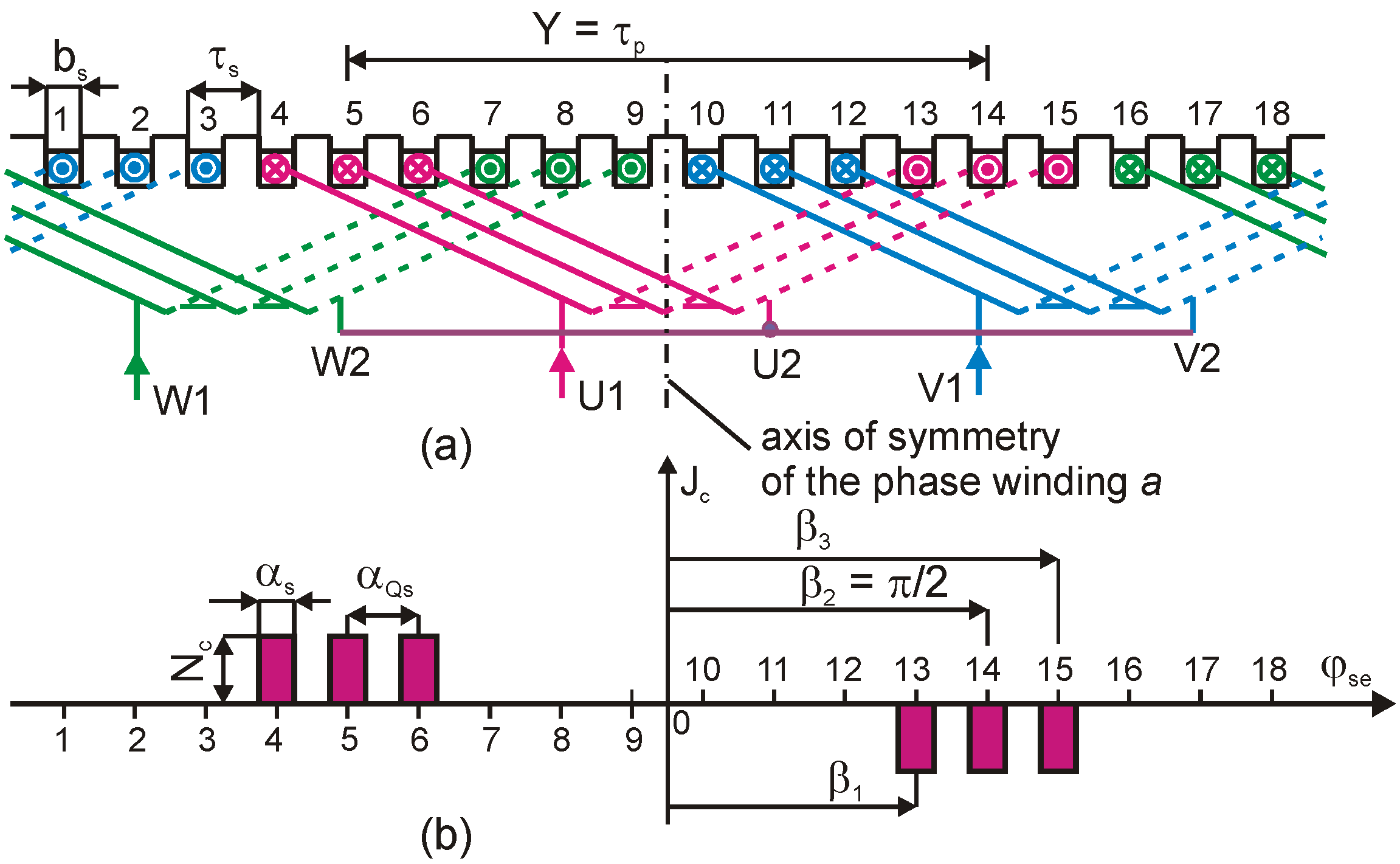
Figure 2.
Double layer winding: (a) winding diagram; (b) resultant linear current density distribution; (c,d) linear current density distributions of single-layer windings.
Figure 2.
Double layer winding: (a) winding diagram; (b) resultant linear current density distribution; (c,d) linear current density distributions of single-layer windings.
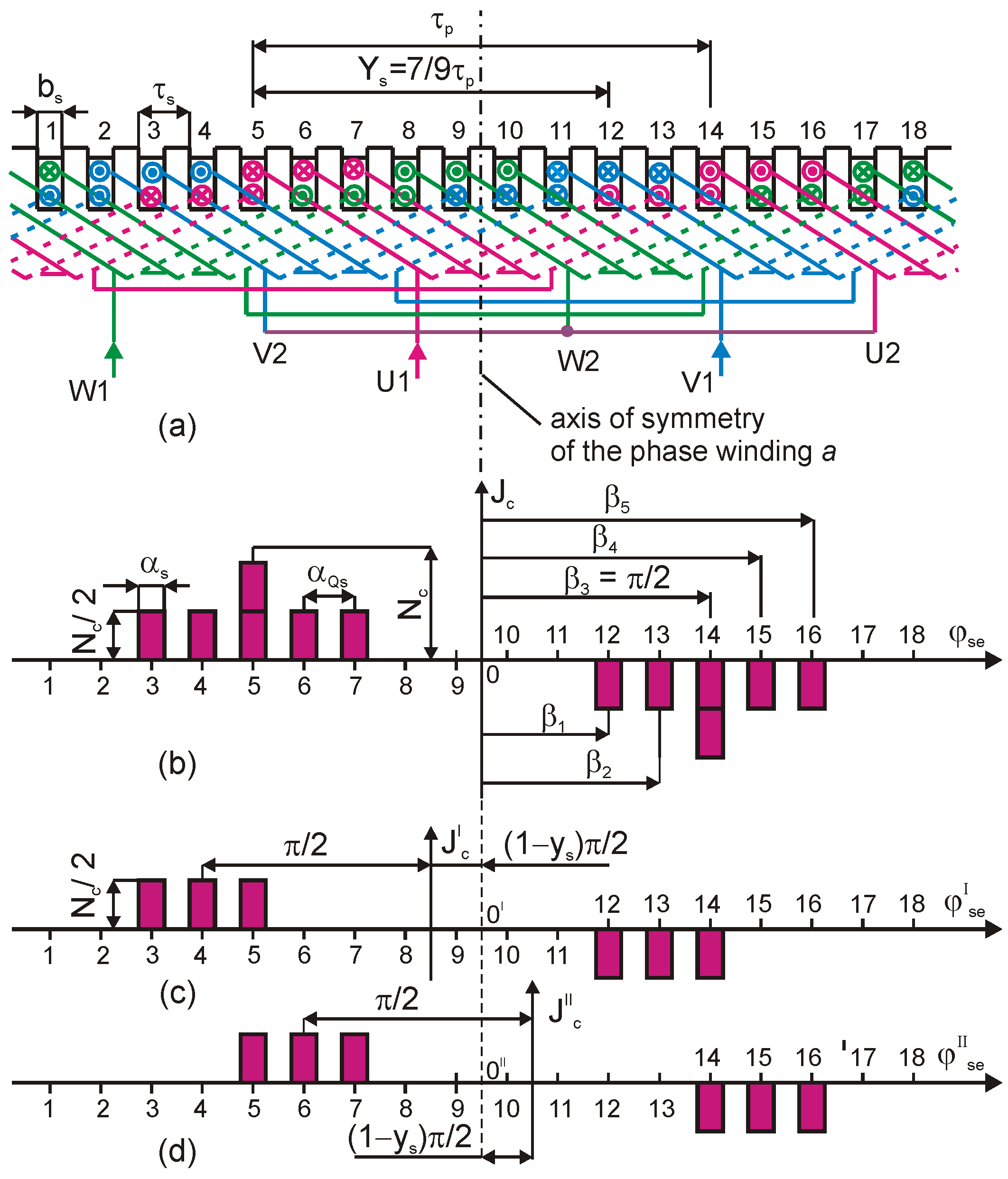
Figure 3.
Three-phase triangle winding: (a) winding diagram; (b) resultant linear current density distribution; (c–e) linear current density distributions of single-layer windings.
Figure 3.
Three-phase triangle winding: (a) winding diagram; (b) resultant linear current density distribution; (c–e) linear current density distributions of single-layer windings.
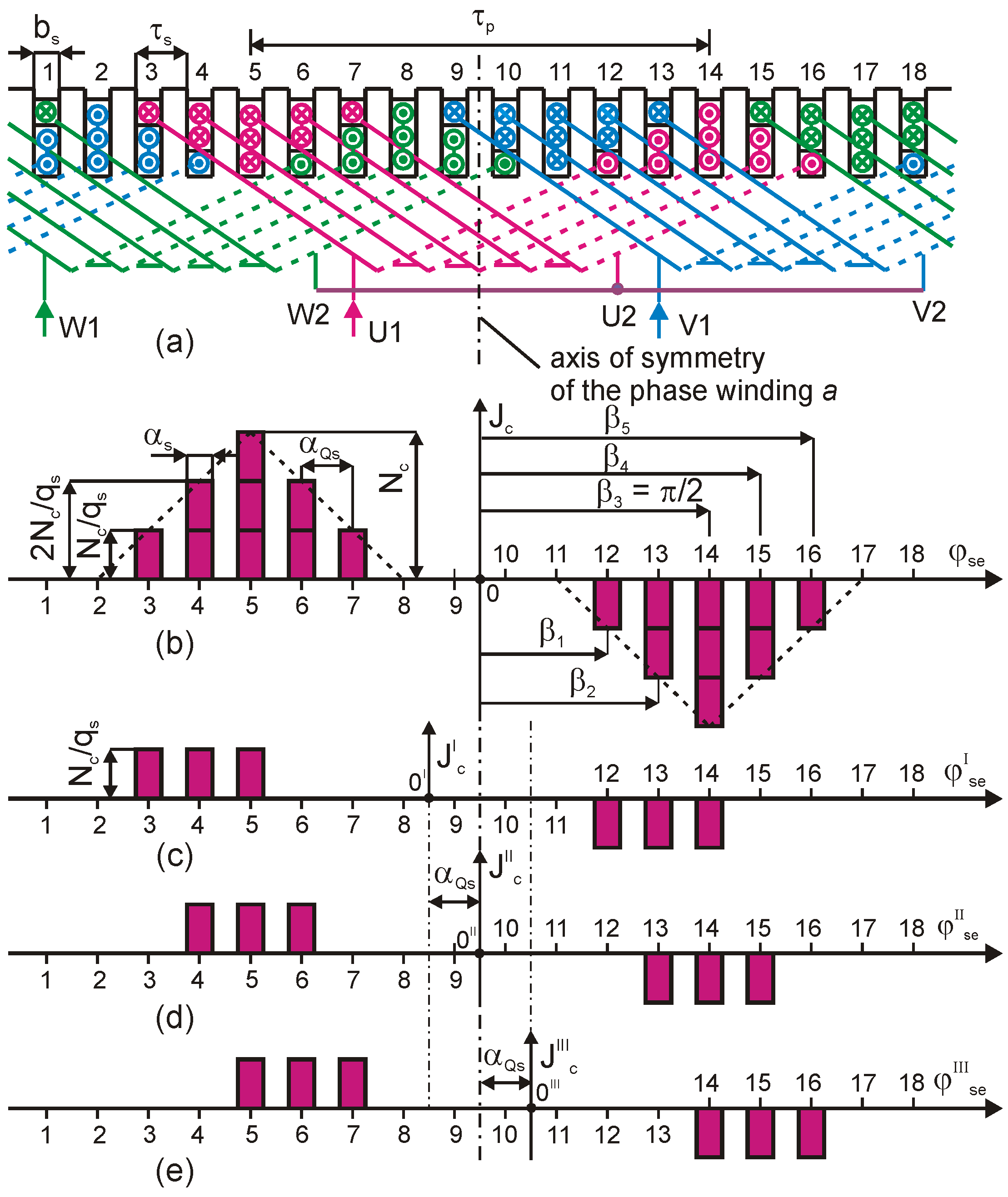
Figure 4.
Modified triangle three-phase winding: (a) winding diagram; (b) linear current density distribution of one phase of the winding: Qs = 18, p =1, and qs = 3.
Figure 4.
Modified triangle three-phase winding: (a) winding diagram; (b) linear current density distribution of one phase of the winding: Qs = 18, p =1, and qs = 3.
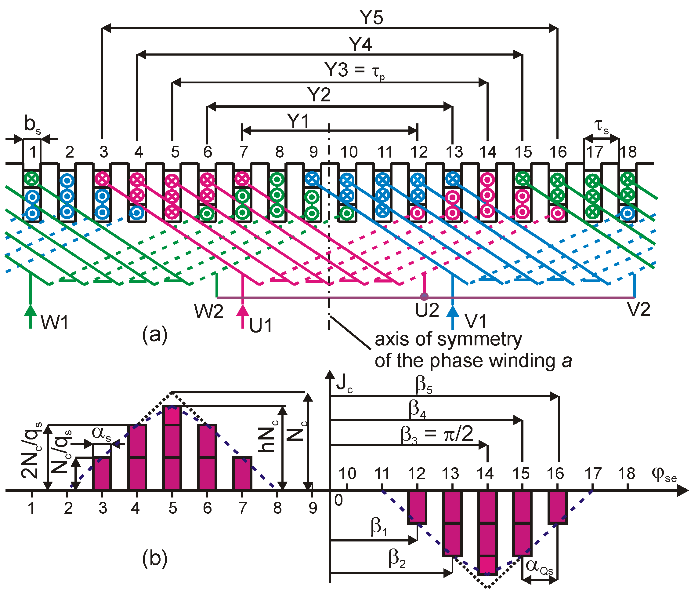
Figure 5.
The star of the slot voltages phasors: (a) for the first harmonic; (b) for the third harmonic; and the voltage polygon: (c) for the first harmonic; (d) for the third harmonic, for a modified triangle winding, with Qs = 18, p = 1, ms = 3, qs = 3, and τp = 9.
Figure 5.
The star of the slot voltages phasors: (a) for the first harmonic; (b) for the third harmonic; and the voltage polygon: (c) for the first harmonic; (d) for the third harmonic, for a modified triangle winding, with Qs = 18, p = 1, ms = 3, qs = 3, and τp = 9.
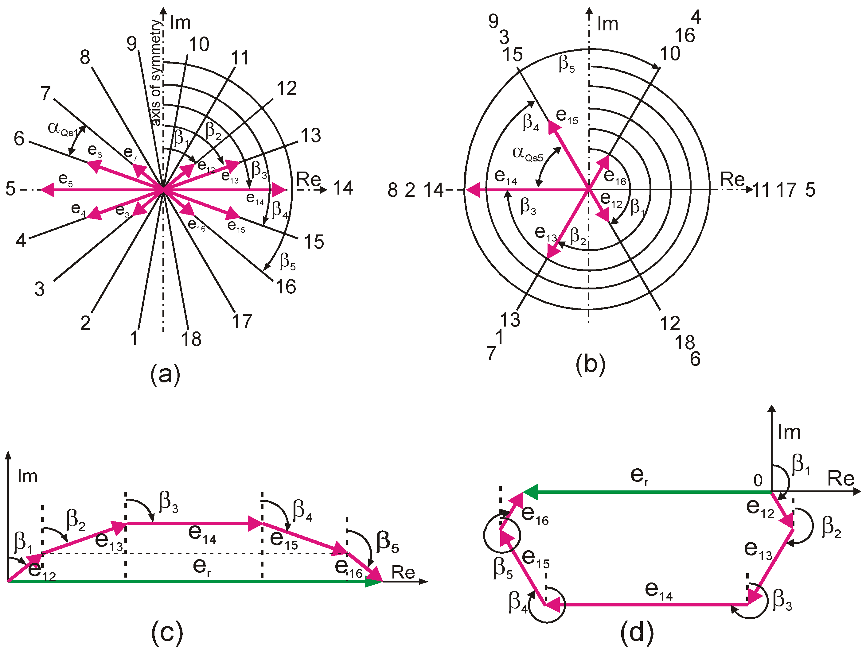
Figure 6.
Three-phase modified triangle winding: (a) winding diagram; (b) linear current density distribution of one phase of the winding, with Qs = 12, p =1, qs = 2, and τp = 6.
Figure 6.
Three-phase modified triangle winding: (a) winding diagram; (b) linear current density distribution of one phase of the winding, with Qs = 12, p =1, qs = 2, and τp = 6.

Figure 7.
Linear current density distribution of one phase of the winding (a) and magnetic flux density distribution (b) produced a three-phase modified triangle winding with Qs = 18, p = 1, qs =3, and h = 0.858.
Figure 7.
Linear current density distribution of one phase of the winding (a) and magnetic flux density distribution (b) produced a three-phase modified triangle winding with Qs = 18, p = 1, qs =3, and h = 0.858.

Figure 8.
Modified triangle two-phase winding: (a) winding diagram; (b) linear current density distribution of one phase of the winding with Qs = 12, p = 1, qs = 3, and τp = 6.
Figure 8.
Modified triangle two-phase winding: (a) winding diagram; (b) linear current density distribution of one phase of the winding with Qs = 12, p = 1, qs = 3, and τp = 6.
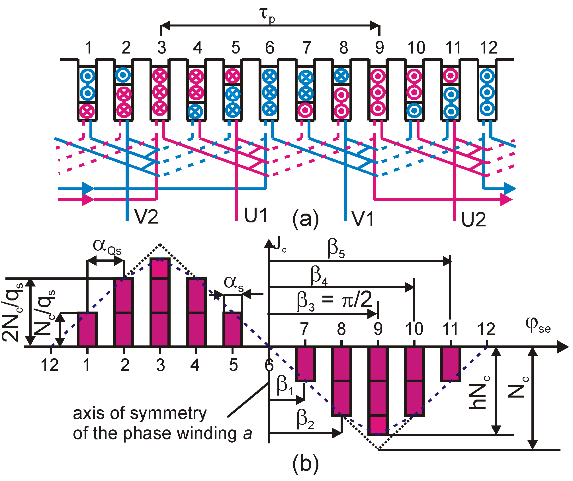
Figure 9.
Two-phase modified triangle winding with Qs = 16, p = 2, qs = 2, ms = 2, and τp = 6, (a) diagram winding; (b), (c) linear current density distribution for phase a and b respectively.
Figure 9.
Two-phase modified triangle winding with Qs = 16, p = 2, qs = 2, ms = 2, and τp = 6, (a) diagram winding; (b), (c) linear current density distribution for phase a and b respectively.
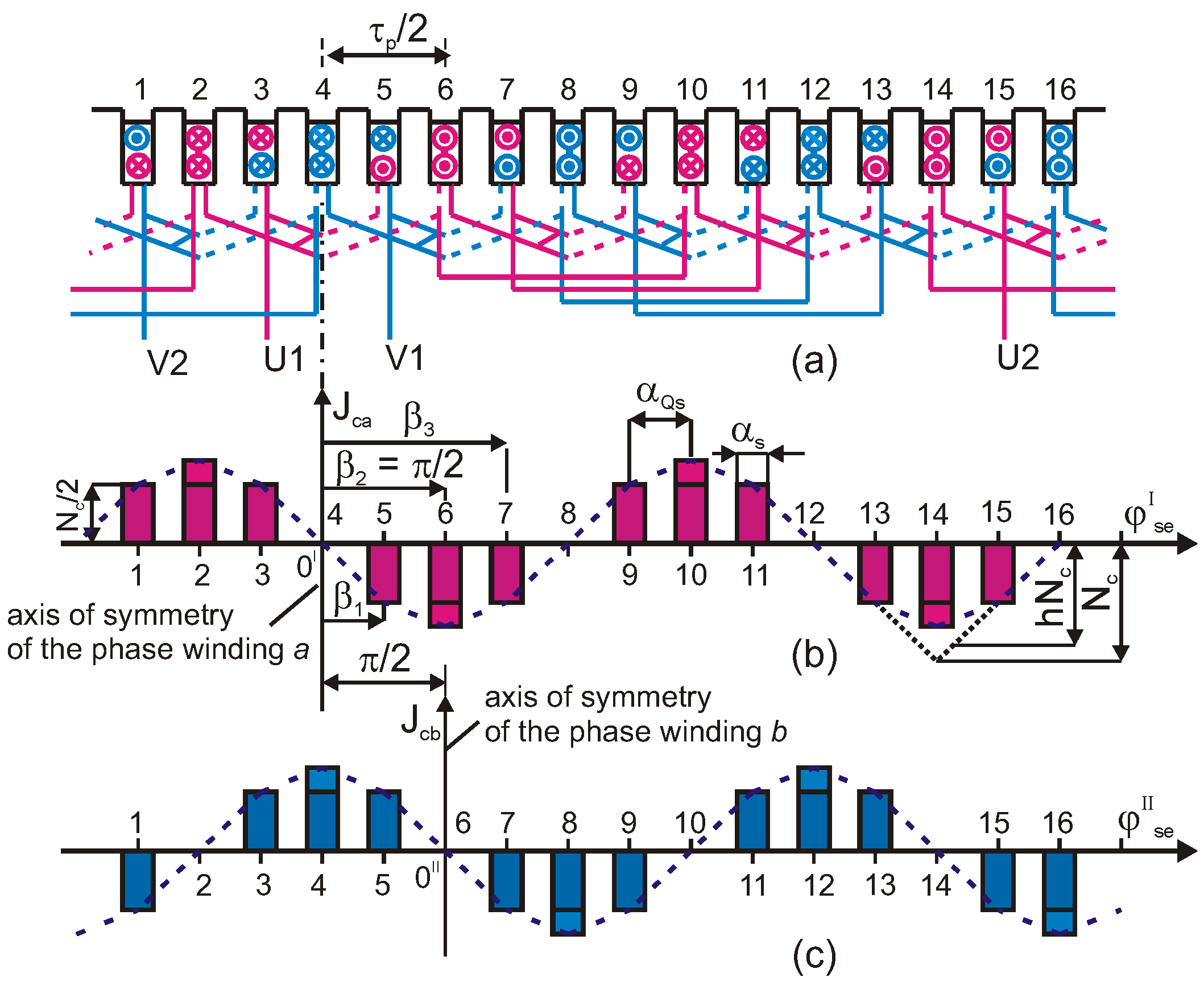
Figure 10.
Structural diagram of a permanent magnet synchronous generator.
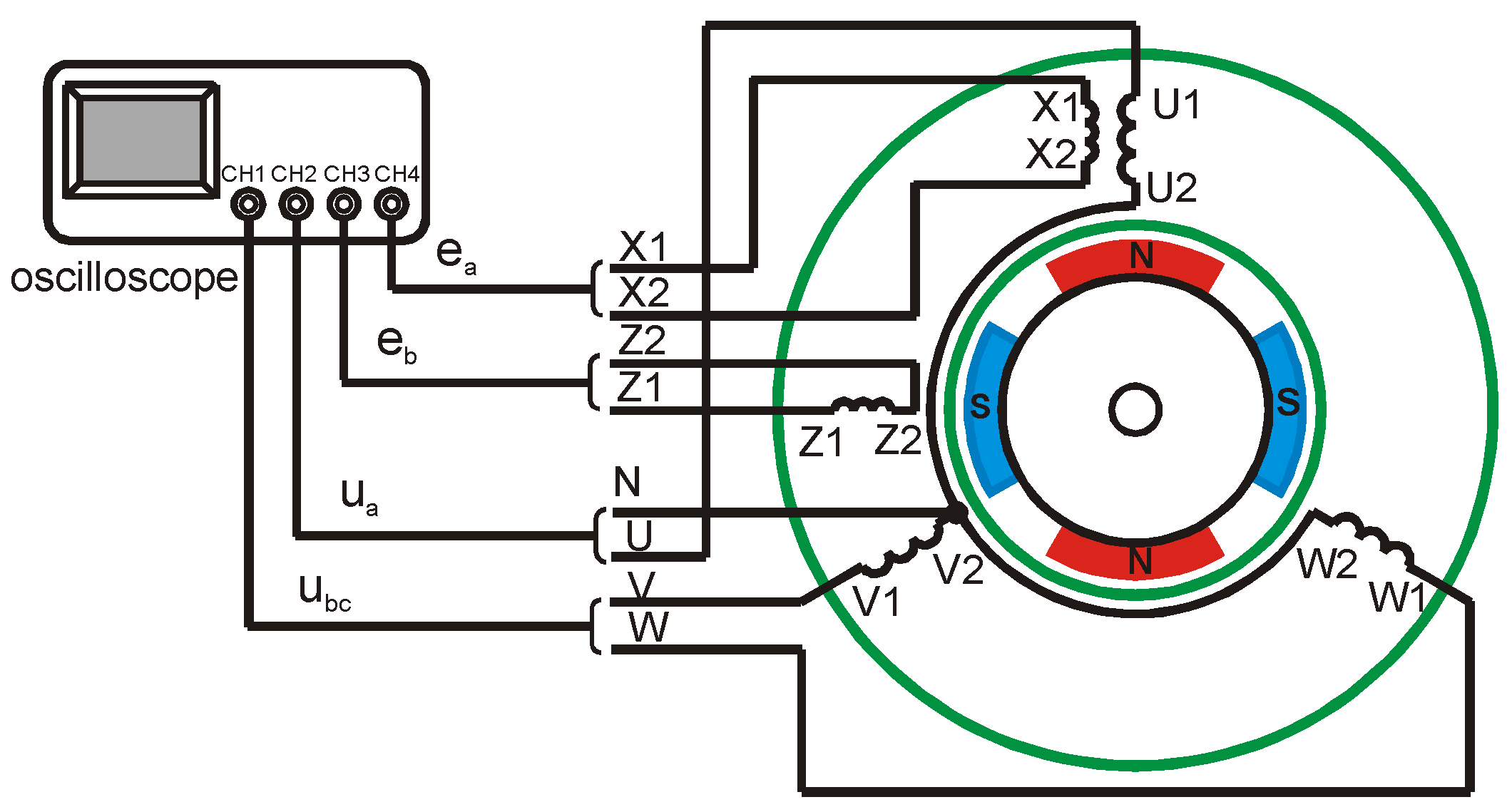
Figure 11.
Diagram of a three-phase modified triangle winding with split groups with Qs = 24, p = 2, qs = 2, and Ys = 4, 6.
Figure 11.
Diagram of a three-phase modified triangle winding with split groups with Qs = 24, p = 2, qs = 2, and Ys = 4, 6.

Figure 12.
Diagram of a two-phase measurement winding with Qs = 24, p = 2, ms =2, and qs = 1.

Figure 13.
Distribution of the normal component of the magnetic flux density in the air gap of a permanent magnet synchronous generator (a); amplitude spectrum of the magnetic flux density (b).
Figure 13.
Distribution of the normal component of the magnetic flux density in the air gap of a permanent magnet synchronous generator (a); amplitude spectrum of the magnetic flux density (b).
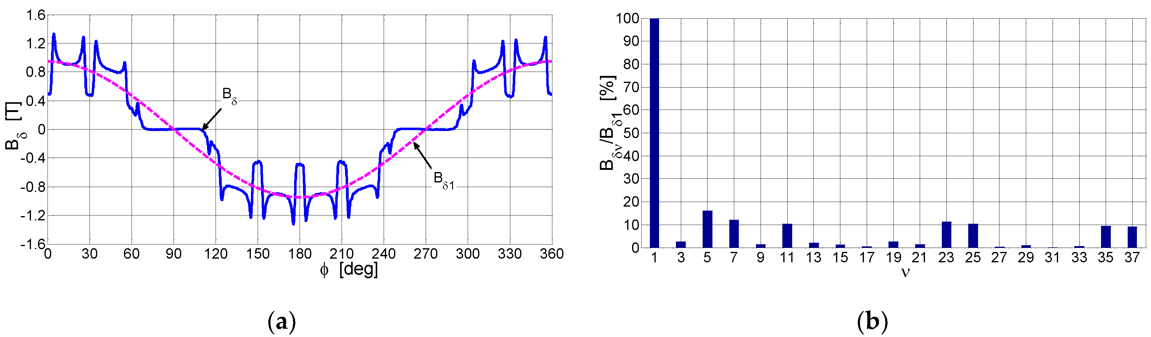
Figure 14.
Registered waveforms of voltages induced in the measurement windings: (a) waveforms of two-phase voltages, ea, eb; (b) voltage trajectory ea = f(eb); (c) waveforms of the higher harmonic components of the voltages; (d) spectral distribution of the voltage amplitude in measurement winding.
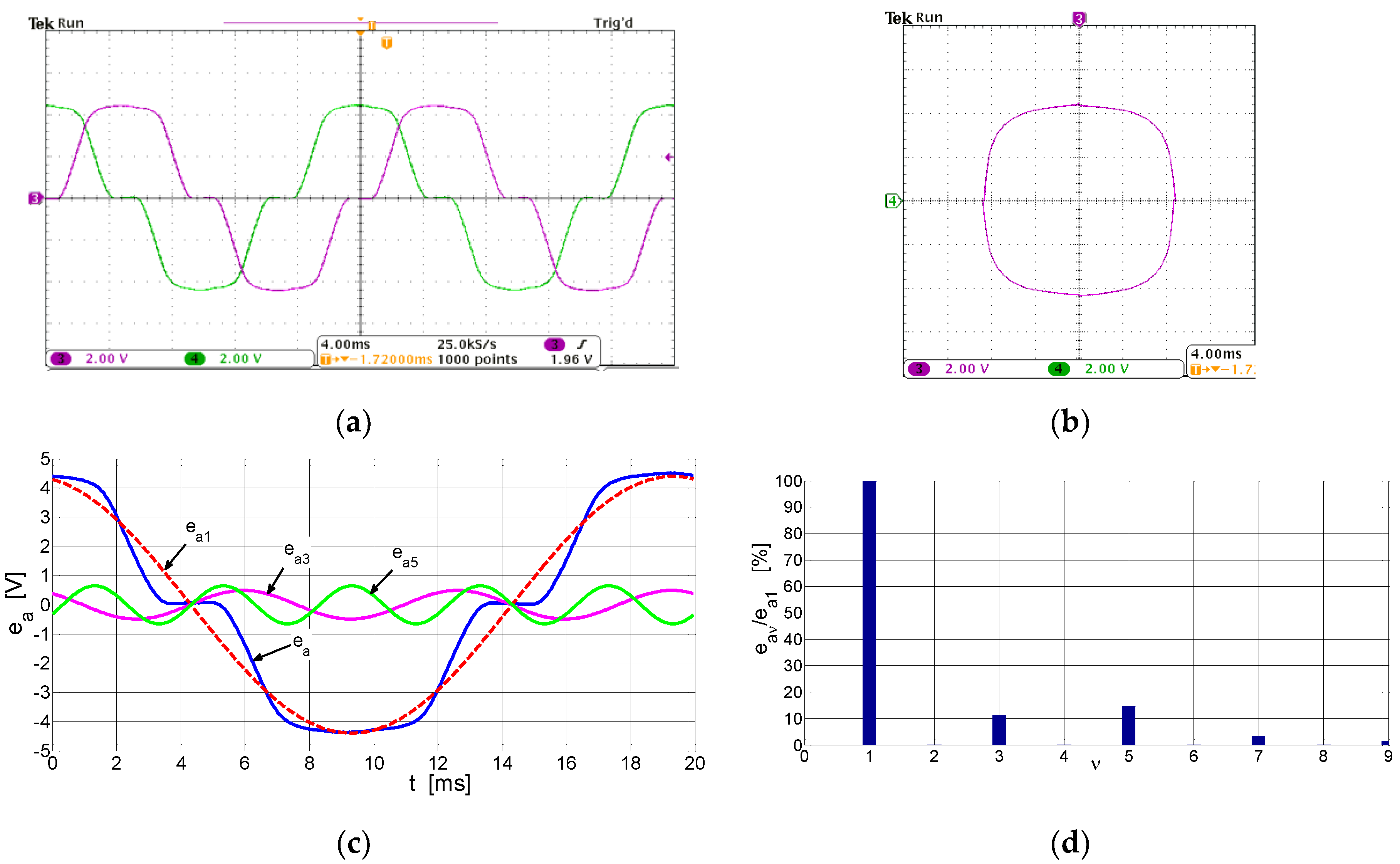
Figure 15.
Phase voltage waveforms induced in the three-phase stator windings of a permanent magnet synchronous generator (a); voltage amplitude spectral distribution (b).
Figure 15.
Phase voltage waveforms induced in the three-phase stator windings of a permanent magnet synchronous generator (a); voltage amplitude spectral distribution (b).

Figure 16.
The line-to-line voltage waveforms induced in the three-phase stator windings of a permanent magnet synchronous generator (a); the spectral distribution of voltage amplitudes (b).
Figure 16.
The line-to-line voltage waveforms induced in the three-phase stator windings of a permanent magnet synchronous generator (a); the spectral distribution of voltage amplitudes (b).

Table 1.
Winding factors for the first and higher harmonics of a three-phase winding with an integer number of slots per pole per phase.
Table 1.
Winding factors for the first and higher harmonics of a three-phase winding with an integer number of slots per pole per phase.
| ν | Double-Layer Winding | Triangle Winding | Triangle Modified | |||
|---|---|---|---|---|---|---|
| ys = 5/6 | ys = 7/9 | h = 1 | h = 1 | h = 0.866 | h = 0.858 | |
| qs | ||||||
| 2 | 3 | 2 | 3 | 2 | 3 | |
| 1 | 0.933013 | 0.901912 | 0.933013 | 0.921207 | 0.928203 | 0.917292 |
| 3 | −0.500000 | −0.333333 | −0.500000 | −0.444444 | −0.464102 | −0.416840 |
| 5 | 0.066987 | −0.037780 | 0.066987 | 0.047336 | 0 | 0 |
| 7 | −0.066987 | −0.135868 | −0.066987 | −0.031458 | 0 | 0.016667 |
| 9 | −0.500000 | 0.333333 | −0.500000 | 0.111111 | 0.464102 | 0.066944 |
| 11 | −0.933013 | −0.135868 | −0.933013 | −0.031458 | −0.928203 | 0.016667 |
| 13 | 0.933013 | −0.037780 | 0.933013 | 0.047336 | 0.928203 | 0 |
| 17 | 0.066987 | 0.901912 | 0.066987 | 0.921207 | 0 | 0.917292 |
| 19 | −0.066987 | −0.901912 | −0.066987 | −0.921207 | 0 | −0.917292 |
Table 2.
Winding factors for the first and higher harmonics of a symmetrical two-phase winding with an integer number of slots per pole per phase.
Table 2.
Winding factors for the first and higher harmonics of a symmetrical two-phase winding with an integer number of slots per pole per phase.
| ν | Double-Layer Winding | Modified Triangle Winding | ||
|---|---|---|---|---|
| ys = 3/4 | ys = 5/6 | h = √3/2 | h = 2/3 | |
| qs | ||||
| 2 | 3 | 2 | 3 | |
| 1 | 0.853553 | 0.879653 | 0.828427 | 0.808013 |
| 3 | −0.146447 | −0.235702 | 0 | 0 |
| 5 | 0.146447 | −0.063156 | 0 | −0.058013 |
| 7 | −0.853553 | −0.063156 | −0.879653 | 0.058013 |
| 9 | 0.853553 | −0.235702 | 0.879653 | 0 |
| 11 | −0.146447 | 0.879653 | 0 | −0.808013 |
| 13 | 0.146447 | −0.879653 | 0 | 0.808013 |
Disclaimer/Publisher’s Note: The statements, opinions and data contained in all publications are solely those of the individual author(s) and contributor(s) and not of MDPI and/or the editor(s). MDPI and/or the editor(s) disclaim responsibility for any injury to people or property resulting from any ideas, methods, instructions or products referred to in the content. |
© 2023 by the author. Licensee MDPI, Basel, Switzerland. This article is an open access article distributed under the terms and conditions of the Creative Commons Attribution (CC BY) license (https://creativecommons.org/licenses/by/4.0/).
Share and Cite
MDPI and ACS Style
Staszak, J. AC Distributed Winding with Low Higher Spatial Harmonics Content in Mmf Distribution. Energies 2023, 16, 5430. https://doi.org/10.3390/en16145430
AMA Style
Staszak J. AC Distributed Winding with Low Higher Spatial Harmonics Content in Mmf Distribution. Energies. 2023; 16(14):5430. https://doi.org/10.3390/en16145430
Chicago/Turabian StyleStaszak, Jan. 2023. "AC Distributed Winding with Low Higher Spatial Harmonics Content in Mmf Distribution" Energies 16, no. 14: 5430. https://doi.org/10.3390/en16145430
Note that from the first issue of 2016, this journal uses article numbers instead of page numbers. See further details here.