
Thermal–Hydraulic Calculation and Analysis on Water Wall System of a 700 MWe Ultra-Supercritical CFB Boiler
1
Key Laboratory for Thermal Science and Power Engineering of Ministry of Education, Department of Energy and Power Engineering, Tsinghua University, Beijing 100084, China
2
Shanghai Boiler Works Co., Ltd., Shanghai 200245, China
3
State Key Laboratory of Power Systems, Department of Energy and Power Engineering, Tsinghua University, Beijing 100084, China
*
Author to whom correspondence should be addressed.
Energies 2023, 16(11), 4344; https://doi.org/10.3390/en16114344
Submission received: 31 March 2023
/
Revised: 21 May 2023
/
Accepted: 23 May 2023
/
Published: 26 May 2023
(This article belongs to the Special Issue Progress and Novel Applications of Fluidized Bed Technology II)
Abstract
:Ultra-supercritical circulating fluidized bed (CFB) boiler combustion technology has the advantages of environmental protection and good commercialization. As one of the key aspects in ultra-supercritical CFB combustion technology, the water wall system directly determines whether the CFB boiler can safely and effectively transform heat energy. This paper studies the thermal–hydraulic characteristics of the designed water wall system of a 700 MWe ultra-supercritical CFB boiler, the largest one that will be built next year. At four loads of the water wall system, hydrodynamic parameters are calculated based on the successfully verified mathematical models. The results show that the hydrodynamic characteristics of the system are good. The temperature distribution of the working fluid and metal of the water wall system is acceptable and safe at each load, which can support the technical development and improvement of the 700 MWe ultra-supercritical CFB boiler.
1. Introduction
Circulating fluidized bed (CFB) boiler technology is one of the best commercially available clean coal combustion technologies in China, playing a pivotal role in the structure of the regional power system. With technological breakthroughs and popularization, CFB boiler technology is particularly advantageous in terms of low cost, high efficiency, and clean coal combustion [1,2,3,4].
CFB boiler technology is also well suited for applications requiring high steam parameters and is capable of achieving supercritical and ultra-supercritical steam conditions, which makes it ideal for use in large-scale power plants, where high efficiency and reliable operation are crucial [5]. In addition, the amount of NOx is limited by controlling the combustion temperature, air staging, lowering excess air, flue gas treatment, controlling the cyclone performance, controlling the coal particle size, or SNCR, resulting in better environmental performance [6,7,8,9]. In addition, SO2 emissions can be controlled by increasing the cyclone efficiency or appropriately reducing the particle size of the limestone, approaching a more ideal desulfurization efficiency [10].
The development of fluidized bed combustion technology in the past century is related to factors such as industrial demand and fuel cost [11]. More recently, however, more consideration has been given to the greenhouse effect. Although the current proportion of fossil fuel consumption such as coal is gradually decreasing, fossil fuel could be expected to remain the mainstream of energy and power industry development for a certain period, especially in China. Therefore, it is still necessary to rely on large power generation equipment such as CFB boilers on the way to achieving the double carbon goal, especially regarding how further improving the efficiency of coal resource utilization with CFB boilers has become the focus of development. Considering the power generation efficiency of CFB boiler units, installed capacity and steam parameters are important indicators [12]. In the pursuit of higher parameters, research support such as high-temperature heating surface safety, hydrodynamic safety, and reheat steam temperature at low load are required [1]. At the same time, it is considered that the demand for the deep peak regulation of boilers increases due to the increase in the proportion of intermittent renewable energy sources such as wind and solar resources [13]. Therefore, exploring low-load operating conditions such as 20% or 30% boiler maximum continuous rating (BMCR) is necessary [12,14,15]. In general, it is hoped to explore the feasibility of CFB boilers with larger capacity and higher steam parameters, while ensuring safe operation at low loads.
Combining the advantages of CFB combustion with low-cost emission control and high efficiency with the supercritical steam cycle, the ultra-supercritical circulating fluidized bed boiler is believed to be the future of CFB combustion technology [5]. With the efforts of researchers since 1990, China’s CFB boilers are continuing to develop on a larger scale. Focusing on the development in recent years, from the first 600 MW supercritical CFB boiler in 2013 to the 660 MW supercritical CFB boiler in 2020 [16], looking forward, the world’s largest-capacity 700 MWe ultra-supercritical CFB boiler will be installed in Shaoguan GuoYue Power Plant in Guangdong, China. Since the boiler structure and layout of the aforementioned 700 MWe ultra-supercritical CFB boilers are different from those with other capacities in the past, it is necessary to model and calculate to verify the safety and feasibility of the boiler.
Determining whether a water wall is properly designed and will operate safely in the future relies on mathematical modeling and thermal–hydraulic analysis. Some of the mathematical modeling and thermal–hydraulic analysis about CFB boilers were performed based on the mass, momentum, and energy conservation equations, proving whether rifled-tube or smooth-tube vertical water walls can meet the safety requirements [17,18]. Existing studies have provided a basis for theoretical calculations, such as the thermal–hydraulic calculation and analysis of water wall systems of 600 and 660 MWe ultra-supercritical CFB boilers [12,19]. In addition, verified by actual data from industrial operation, it is shown that by adopting smooth tubes and low-mass-flux technology, the hydrodynamic characteristics are safe and reliable [12]. Especially, the heat flux of the CFB boiler furnace is lower than that of the pulverized coal furnace, so there are usually more heating surface structures, such as the water-cooled panels in this study, especially for the ultra-supercritical steam cycle [20]. In addition, it is important to determine how to improve the flow maldistribution caused by the geometric structure of the boiler or a heat flux deviation.
In summary, aiming to verify the performance of the water wall system of a 700 MWe ultra-supercritical CFB boiler, based on previous models and the aforementioned characteristics of the research object [12], the thermal–hydraulic parameters of the water wall system at different loads were calculated and analyzed. It is expected to provide a design reference and support for the technical development and design of 700 MWe ultra-supercritical CFB boilers.
2. Boiler Structure and Design Parameters of Water Wall System
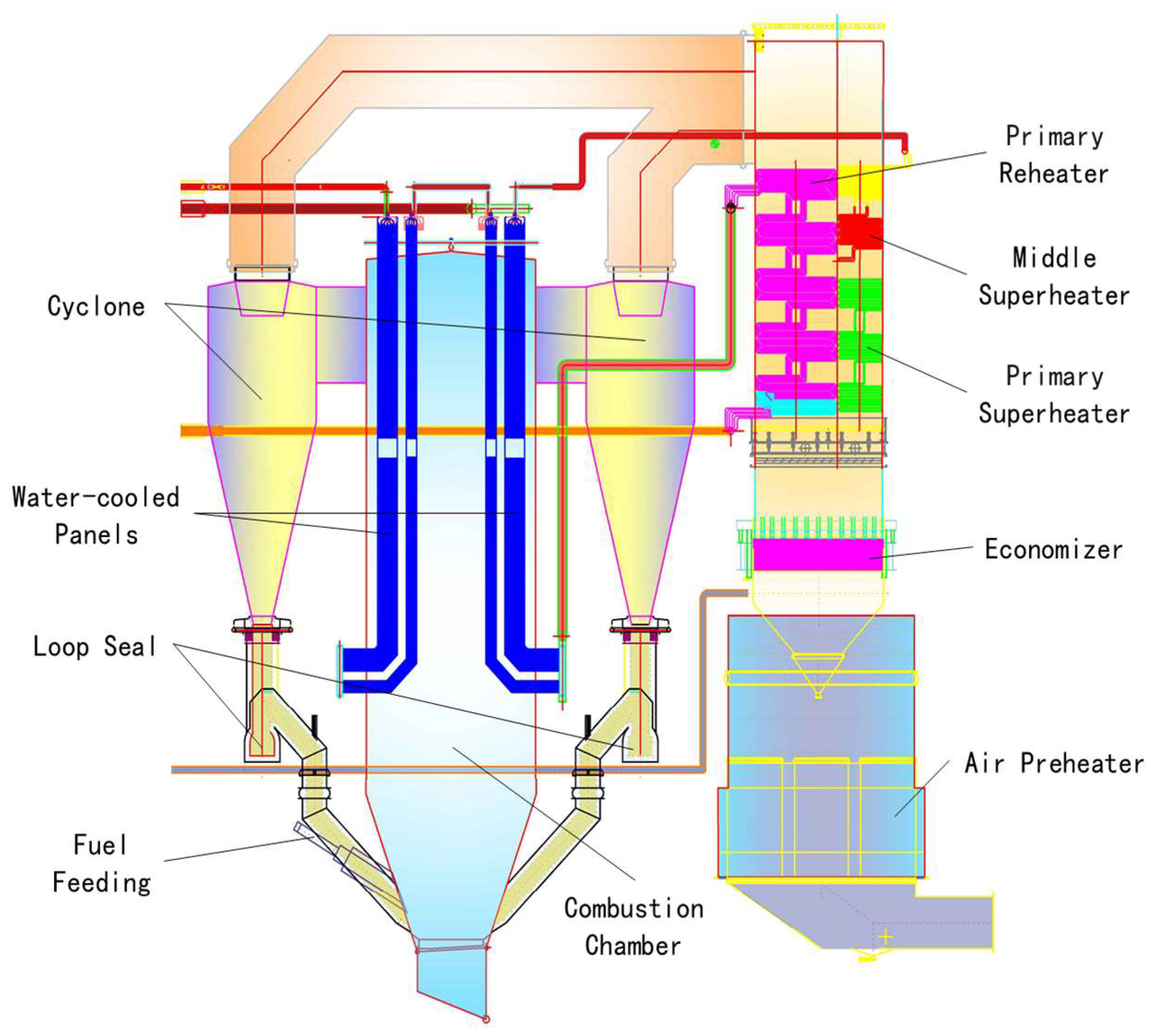
An ultra-supercritical once-through single furnace boiler with a single air distribution plate structure is shown in Figure 1. In addition, there are eight cyclones arranged in the front and rear walls of the boiler. Such features are totally different to those of the 600 MW supercritical CFB boiler and 660 MW ultra-supercritical CFB boiler [12]. The boiler with a furnace width of 39,025 mm and a depth of 12,505 mm is arranged symmetrically and supported on the steel frame.
The evaporative heating surface is composed of vertical water walls and water-cooled panels, which are arranged in series to ensure adequate heat absorption. Both the front and rear walls of the lower part of the water wall are composed of 325 Φ60 mm smooth tubes (Φ refers to the diameter of the tube, same meaning below) with a 120 mm pitch, while the upper part is composed of 650 Φ35 mm smooth tubes with a 60 mm pitch. The front and rear walls are bent toward the center of the furnace to form the furnace roof. In addition, the upper part and the lower part of the water wall are connected by a Y-type tee.
Both the right and left walls of the lower part of the water wall consist of 104 Φ60 mm smooth tubes with a 120 mm pitch, while the upper part consists of 208 Φ35 mm smooth tubes with a 60 mm pitch. There are 10 water-cooled panels on the upper part of the rear wall near the left and right walls, each of which is composed of 36 tubes of Φ51 mm.
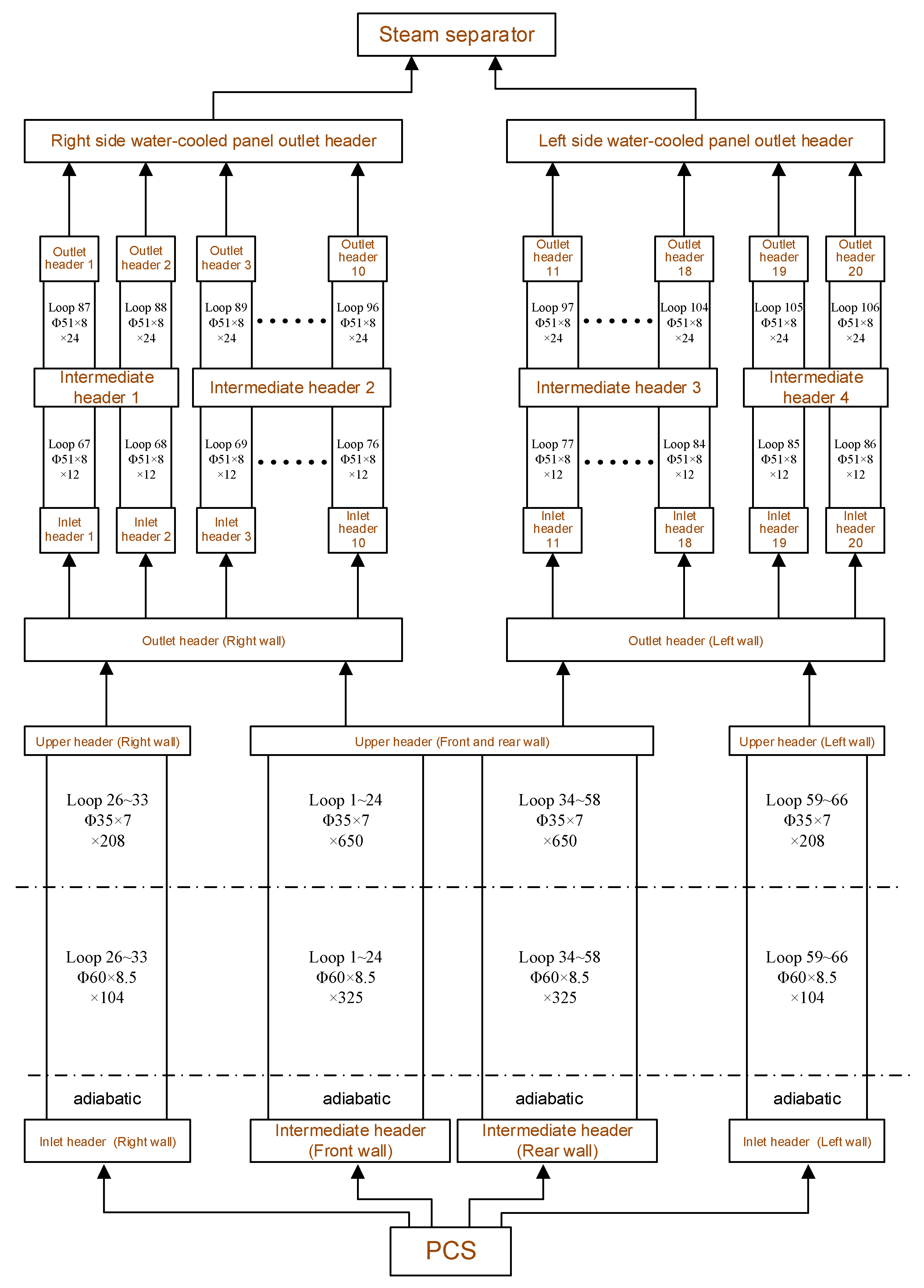
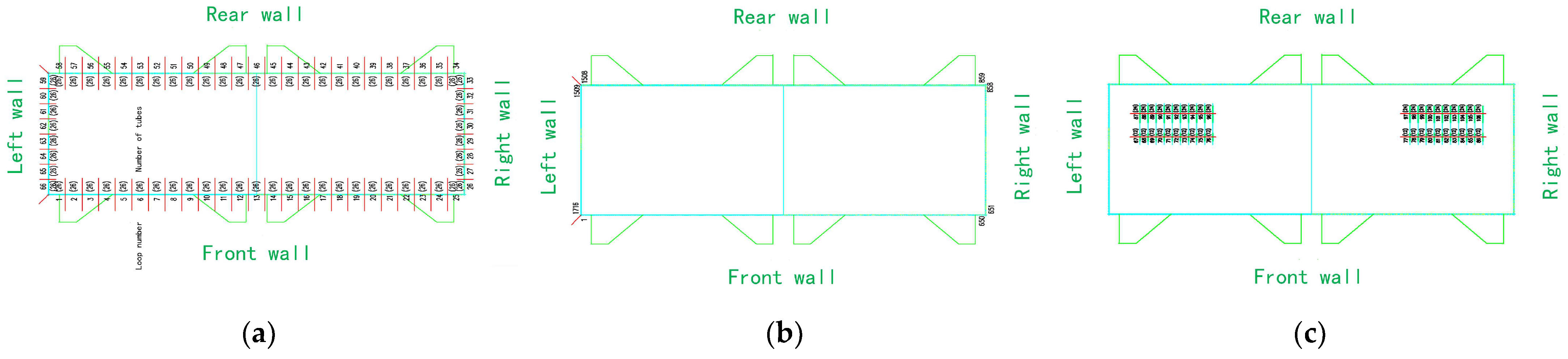
The working fluids of the front wall and the rear wall originate from their respective intermediate headers and flow to a mutual upper header located in the upper part of the furnace. As for the left and right walls, the working fluid enters two upper headers separately. A total of 3 upper headers of water walls are connected to the outlet headers of the left and right walls, which then lead to 20 inlet headers of water-cooled panels through 20 tubes of Φ168 mm. Then, the working fluid enters the water-cooled panels from the small inlet headers, flowing through the downcomer pipes, the middle intermediate headers, the riser tubes, the outlet header, and finally entering the separator, as shown in Figure 2. The hydraulic design parameters and characteristic parameters at different operation loads are summarized in Table 1, where the abbreviation BMCR refers to the boiler maximum continuous rating, which characterizes the rated load without causing damage to each component. The flow loop division of the water wall system is shown in Figure 3 with the serial number of the tubes.
3. Mathematical Model and Calculation Method
For our research object, the water wall system of a 700 MW ultra-supercritical CFB boiler, the mathematical model and calculation method selected are basically the same as the research conducted by Tang et al. [12], which is also based on mass conservation, energy conservation, and pressure balance to predict the working fluid flow, heat transfer, and temperature conditions of the water wall system. The formulas and methods involved in the model have been verified by years of research and commercial CFB boilers. In other words, most coefficients in the model have been determined according to industrial experience and actual boiler structure, so are considered to have a certain degree of reliability.
Some important formulas of the model are listed below for reference. For example, the heat transfer calculation part of the water wall system uses the model proposed by Lyu, which covers the heat transfer surface configuration, heating conditions, and solid suspension density [21,22]. Particularly, it is known in industrial experience that the relative suspension density of solid particles at different heights in the furnace is very close, so the distribution of the suspension density of materials in the model could be calculated as:
where X and Y are the relative depth and width of the furnace, respectively; DX, DY, and DZ are the relative suspension densities of solid materials in the three-dimensional direction in the furnace.
On the other hand, for the connecting tubes, the Dittus–Boelter correlation is used to calculate the heat transfer coefficients of single-phase subcritical working fluids and supercritical fluids outside the large specific heat region. In addition, the standard of the boiler hydrodynamics calculation of China is used to calculate the heat transfer coefficient of the two-phase region [23]. As for the large-specific-heat region at supercritical pressure, the heat transfer coefficient is determined by the Mokry correlation.
For pressure balance, the gravitational pressure drop, frictional pressure drop, acceleration pressure drop, and local pressure drop determine the total pressure drop of each section of loop [12,19]:
where the calculating methods of f1 to f4 are the same as the method in the literature [12].
As for the calculation of the water wall temperature, the following relationship is established, also based on the standard [23]:
where and are the inner and outer wall temperatures, respectively; is the temperature of the fluid in the tube at the calculation point of the wall temperature; is the heat flux on the outer wall at the calculation point of wall temperature; is the coefficient related to the uniformity of heat flow on the inner wall of the tube; and are the outer diameter and inner diameter of the tube, respectively; is the heat transfer coefficient of the working fluid in the tube; is the average coefficient of the front of the tube along the thickness direction; is the thickness of the tube wall; is the metal thermal conductivity of the tube.
According to the given parameters and theoretical formulas, the program iteratively calculates and finally obtains the result.
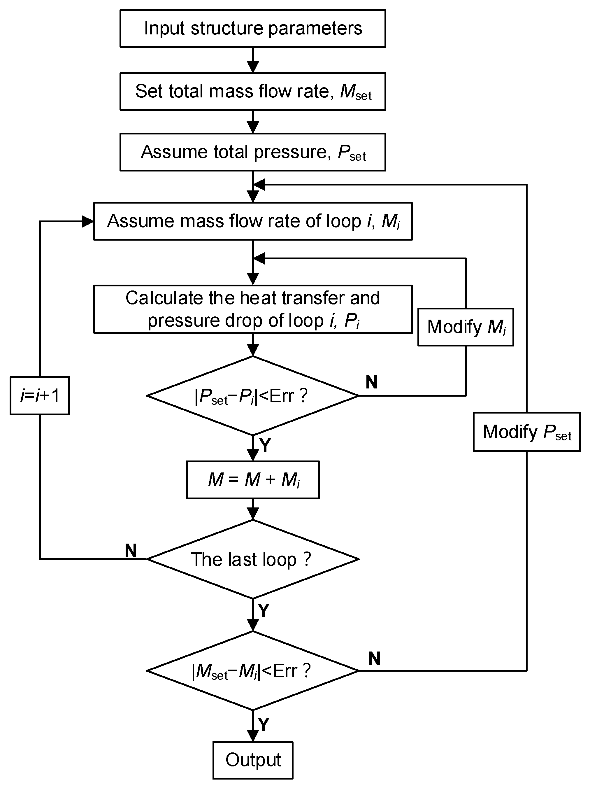
The calculation process is shown in Figure 4. First, the structure parameters are input; then, the total mass flow rate is set; finally, the total pressure and other thermal parameters are iteratively solved. Among them, several adjacent pipes are regarded as a group of loops to facilitate calculation, and each loop is divided into several micro-element pipe sections of a certain length as calculation units. The heat flux density in the unit is assumed to be uniform and the working fluid parameters in the unit are taken as the average value of the inlet and outlet. In this way, results can be iteratively calculated from small units to large loops according to the formula of the mathematical model and the flow of the program.
Other assumptions exist to simplify calculations. For example, except for the inlets of the hot cyclone and the return ports of the loop seal, the structure’s influences on the water wall caused by the holes are ignored during the calculation. In addition, the header effects of all headers are ignored.
4. Calculation Results and Discussion
4.1. Hydrodynamic Characteristics at Different Loads
The calculation results of hydrodynamic characteristic parameters of the water wall and water-cooled panel at different boiler loads are shown in Table 2, which can be seen as consistent with design values (in Table 1) of the pressure drop and temperature of the water wall system. The lower total pressure drop also helps the boiler to operate economically [24].
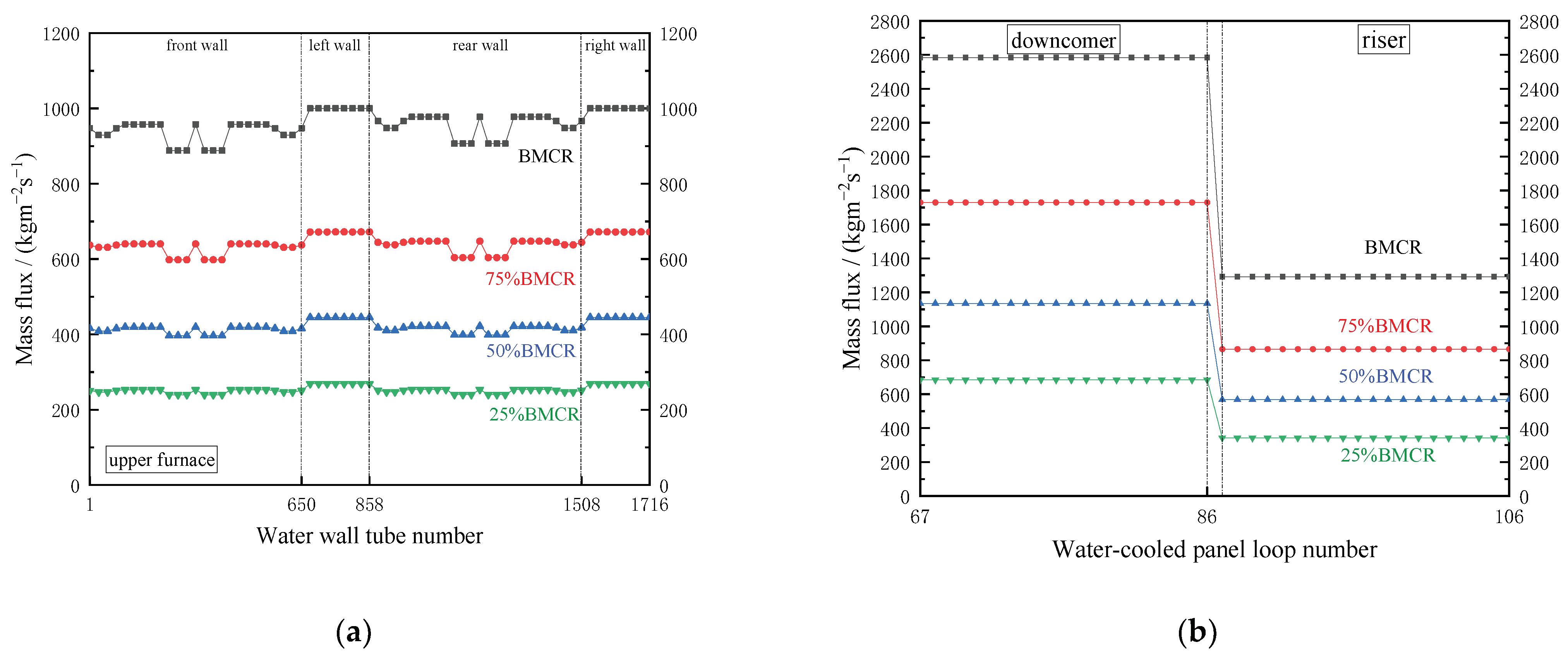
Figure 5 shows the mass flux distribution in the water wall system, including the water wall and water-cooled panels, at different loads. The mass flux of the front and rear walls is less than that of the left and right walls because the tubes of the rear walls need to be longer to bend to form the roof, which also results in greater flow resistance. Analogously, the mass flux distribution of the front and rear walls is battlemented, where the low-mass-flux areas correspond to the flow loops associated with the inlets of the hot cyclones, due to the presence of the hot cyclones and the complex arrangement of the associated tubes, resulting in greater flow resistance.
The mass flux distribution of the water-cooled panels is shown in Figure 5b, from which the value of the downcomer water-cooled panel is significantly higher than that of the riser tubes, not only because of the difference in flow direction arrangement between them, but also because twice the number of pipes also brings greater flow resistance.
4.2. Heat Flux Distribution
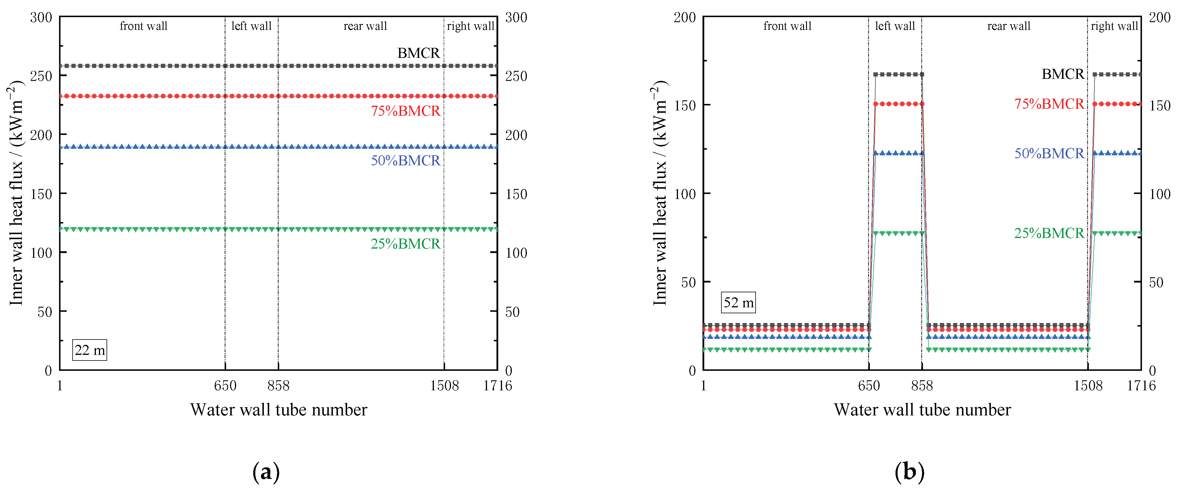
The horizontal heat flux distribution on the water wall is shown in Figure 6. As shown in Figure 6a, the heat fluxes of different pipes at a height of 22 m are equal at different loads. Figure 6b shows that at a height of 52 m, the four water walls have their own equivalence at different loads, where the heat flux of the left and right walls is significantly higher than that of the front and rear walls.
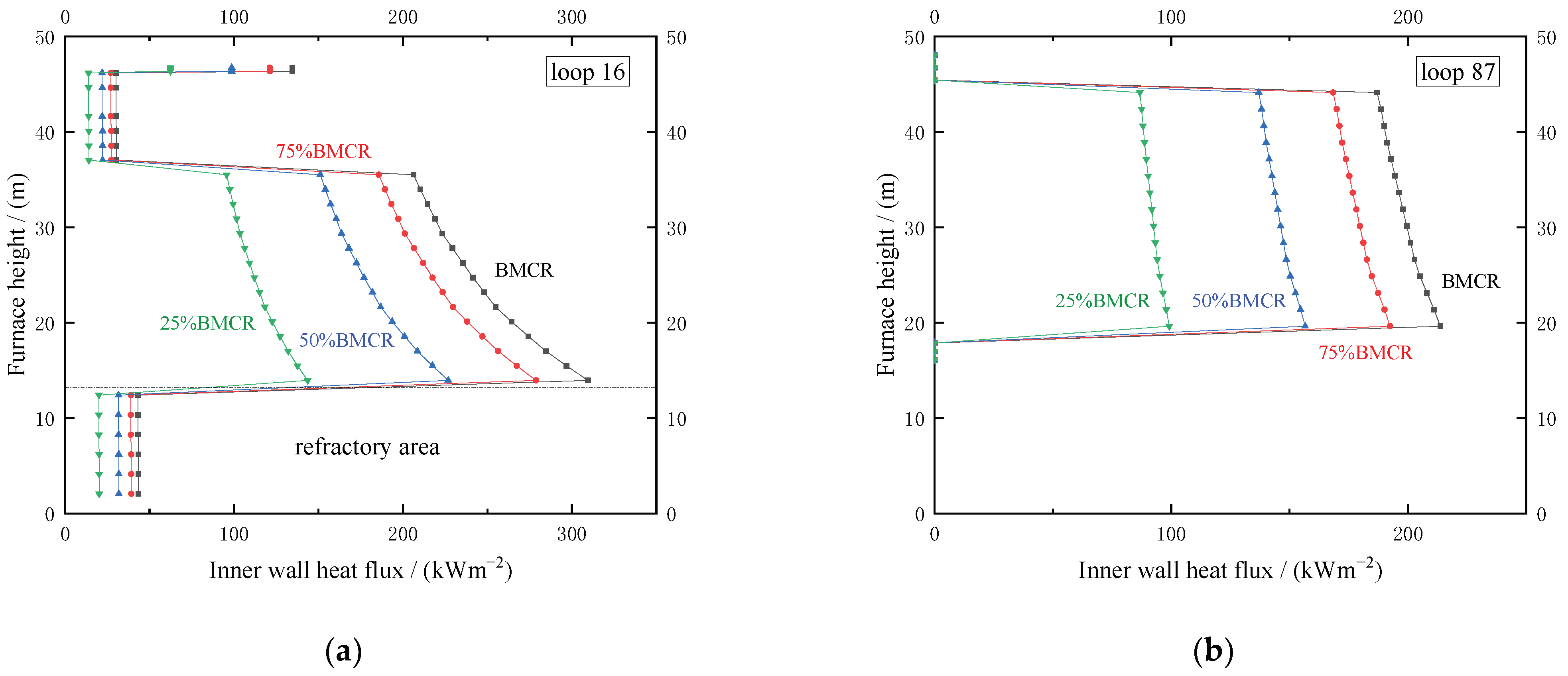
Figure 7 illustrates how the heat flow is distributed with the height of the furnace, where Figure 7a is the case of loop 16 with the highest temperature on the front wall and Figure 7b is the case of loop 87 with the highest temperature of the water-cooled panel. For the water wall, the refractory area below about 13 m corresponds to the lower inner wall heat flux due to the arrangement of the refractory covering. Continuing upward, the heat flux gradually decreases until restrained by the refractory covering at a height of 37 m, and this trend remains consistent at different loads. The development trend of the heat flux along the height in the water-cooled panels is also the same, except for the refractory area, where the heat flux increases with the height of the furnace.
4.3. Outlet Fluid Temperature
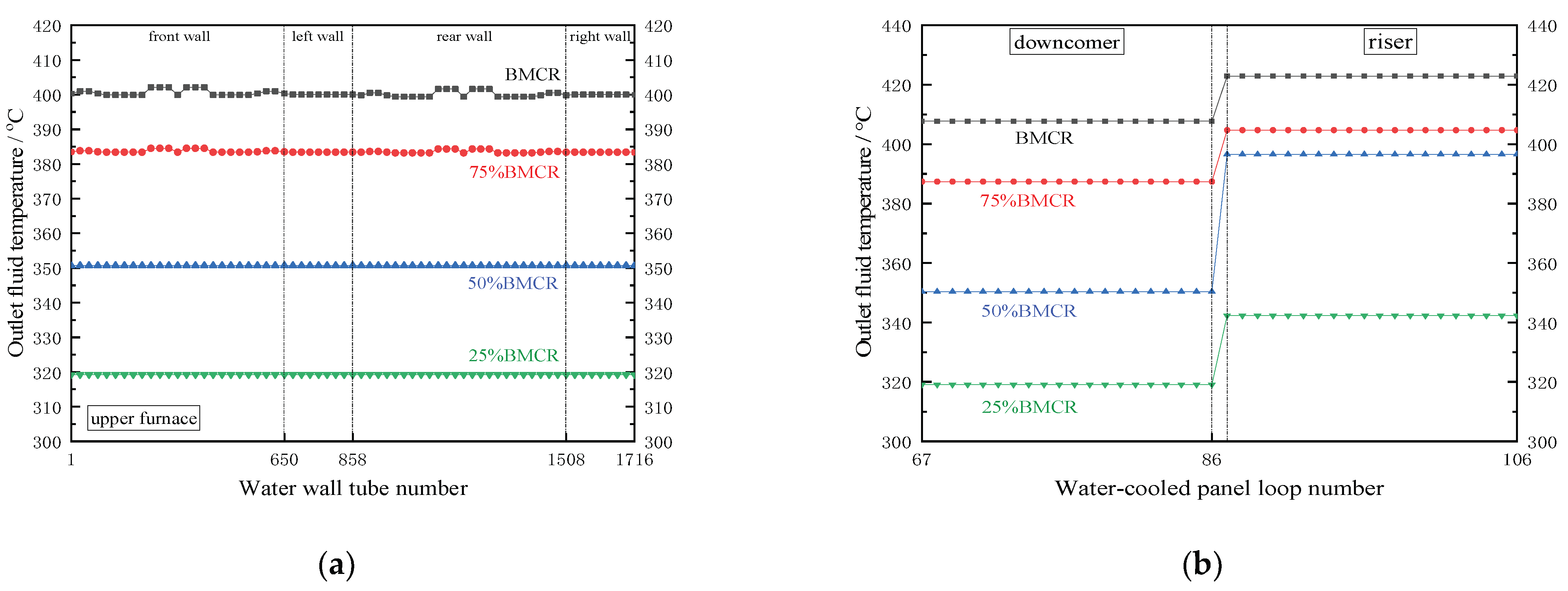
The outlet fluid temperature distribution of the water wall system is shown in Figure 8. The distribution of mass flux effectively solves the inhomogeneity of heat flux, making the fluid temperature of adjacent outlets in the same area sufficiently small, as shown in Figure 8a. At BMCR load, the maximum difference between the outlet fluid temperature of the front wall and the rear wall is 2 °C, and the temperature inhomogeneity corresponds to the low-mass-flux area in Figure 5a, which is similar at 75% BMCR load. Furthermore, at 50% and 25% BMCR load, the outlet fluid temperature difference between different tubes of the water wall does not exist, because the working fluid at the outlet of the water wall is in the two-phase region.
As for the water-cooled panel, the outlet fluid temperature distribution in each area is quite uniform, and the temperature difference between the downcomer and riser tubes arranged successively is also in line with the prediction. For example, the outlet fluid temperature of the water-cooled panel is overheated by 24 °C at 25% BMCR load.
4.4. Metal Temperature Distribution
For safe operation, it is necessary to confirm the maximum metal temperature of the tubes. Figure 9 shows the temperature distribution along the flow direction in loop 16 and loop 87, which are the tubes with the highest outlet temperature in the water wall and water-cooled panels, respectively.
As shown in Figure 9a, at BMCR load, the fluid temperature increases monotonically with height. Around the area below 13 m, the temperature difference between the fluid and metal is small because the refractory is covered to prevent erosion. Similarly, the small temperature difference in the height range from 35 to 46 m is also due to the refractory covering and to the hot cyclone inlet area where the heat flux is smaller. Above the height of 46 m—the roof area—the temperature rises again due to the recovery of heat flux. In this loop, the maximum temperature is 437.7 °C at the height of 35.5 m. As for 25% BMCR load, the main difference from the former is that the lower pressure saturates the fluid at a height of about 18.5 m, so the fluid temperature remains almost unchanged even until reaching the height of 46 m with a maximum temperature of 320 °C.
As for the water-cooled panel, the fluid temperature and wall temperature increase monotonically along the direction of flow. In addition, the temperature difference between the fluid and metal is larger at 25% BMCR load. Below 18 m, the temperature difference between the fluid and metal is small due to the refractory preventing erosion. Between about 38 and 45 m, the temperature begins to rise gradually, which corresponds to the overheated state of the working fluid; above 45 m, because of the water-cooled panel out of the furnace, the fluid temperature is consistent with the metal.
5. Conclusions
The thermal–hydraulic calculation model and method of the water wall system of the 700 MWe ultra-supercritical CFB boiler are described. The thermal–hydraulic characteristics of the water wall system are analyzed at four loads of 100% BMCR, 75% BMCR, 50% BMCR, and 25% BMCR.
The results prove that the mass flux and temperature distribution of working fluid are relatively average and acceptable at different loads. The metal temperature distribution also ensures the safe operation of the water wall system, even at 25% loads. Based on the above, the design of the water wall system of the 700 MWe ultra-supercritical CFB boiler is feasible.
Funding
This work was financially supported by the National Key Research Plan (2019YFE0102100) and the C9 University Science and Technology Project (201903D421009).
Data Availability Statement
The data presented in this study are available on request from the corresponding author.
Conflicts of Interest
The authors declare no conflict of interest.
References
- Cai, R.; Lu, J.; Ling, W. Progress of supercritical and ultra-supercritical circulating fluidized bed boiler technology. Electr. Power 2016, 49, 1–7. [Google Scholar]
- Yu, L.; Lu, J.-F.; Yue, G.-X. Prospective research progress of combustion technology for circulating fluidized beds. J. Eng. Therm. Energy Power 2004, 19, 336–342. [Google Scholar]
- Koornneef, J.; Junginger, M.; Faaij, A. Development of fluidized bed combustion—An overview of trends, performance and cost. Prog. Energy Combust. Sci. 2007, 33, 19–55. [Google Scholar] [CrossRef]
- Yue, G.; Cai, R.; Lu, J.; Zhang, H. From a CFB reactor to a CFB boiler–The review of R&D progress of CFB coal combustion technology in China. Powder Technol. 2017, 316, 18–28. [Google Scholar]
- Lyu, J.; Yang, H.; Ling, W.; Nie, L.; Yue, G.; Li, R.; Chen, Y.; Wang, S. Development of a supercritical and an ultra-supercritical circulating fluidized bed boiler. Front. Energy 2019, 13, 114–119. [Google Scholar] [CrossRef]
- Ji, J.; Cheng, L.; Wei, Y.; Wang, J.; Gao, X.; Fang, M.; Wang, Q. Predictions of NOx/N2O emissions from an ultra-supercritical CFB boiler using a 2-D comprehensive CFD combustion model. Particuology 2020, 49, 77–87. [Google Scholar] [CrossRef]
- Blaszczuk, A.; Nowak, W.; Jagodzik, S. Effects of operating conditions on deNOx system efficiency in supercritical circulating fluidized bed boiler. J. Power Technol. 2013, 93, 1. [Google Scholar]
- Ke, X.; Yao, Y.; Huang, Z.; Zhang, M.; Lyu, J.; Yang, H.; Zhou, T. Prediction and minimization of NOx emission in a circulating fluidized bed combustor: Improvement of bed quality by optimizing cyclone performance and coal particle size. Fuel 2022, 328, 125287. [Google Scholar] [CrossRef]
- Yan, J.; Lu, X.F.; Zhang, C.F.; Li, Q.J.; Wang, J.P.; Liu, S.R.; Zheng, X.; Fan, X.C. An Experimental Study on the Characteristics of NOx Distributions at the SNCR Inlets of a Large-Scale CFB Boiler. Energies 2021, 14, 1267. [Google Scholar] [CrossRef]
- Ke, X.; Li, D.; Li, Y.; Jiang, L.; Cai, R.; Lyu, J.; Yang, H.; Zhang, M.; Jeon, C.-H. 1-Dimensional modelling of In-Situ desulphurization performance of a 550 MWe ultra-supercritical CFB boiler. Fuel 2021, 290, 120088. [Google Scholar] [CrossRef]
- Leckner, B. Hundred years of fluidization for the conversion of solid fuels. Powder Technol. 2022, 411, 117935. [Google Scholar] [CrossRef]
- Tang, G.; Zhang, M.; Gu, J.; Wu, Y.; Yang, H.; Zhang, Y.; Wei, G.; Lyu, J. Thermal-hydraulic calculation and analysis on evaporator system of a 660 MWe ultra-supercritical CFB boiler. Appl. Therm. Eng. 2019, 151, 385–393. [Google Scholar] [CrossRef]
- Xin, S.; Wang, H.; Li, J.; Wang, G.; Wang, Q.; Cao, P.; Zhang, P.; Lu, X. Discussion on the Feasibility of Deep Peak Regulation for Ultra-Supercritical Circulating Fluidized Bed Boiler. Energies 2022, 15, 7720. [Google Scholar] [CrossRef]
- Domenichini, R.; Mancuso, L.; Ferrari, N.; Davison, J. Operating flexibility of power plants with carbon capture and storage (CCS). Energy Procedia 2013, 37, 2727–2737. [Google Scholar] [CrossRef]
- Henderson, C. Increasing the flexibility of coal-fired power plants. IEA Clean Coal Cent. 2014, 15, 15. [Google Scholar]
- Cai, R.; Ke, X.; Lyu, J.; Yang, H.; Zhang, M.; Yue, G.; Ling, W. Progress of circulating fluidized bed combustion technology in China: A review. Clean Energy 2017, 1, 14. [Google Scholar] [CrossRef]
- Zhu, X.; Wang, W.; Xu, W. A study of the hydrodynamic characteristics of a vertical water wall in a 2953t/h ultra-supercritical pressure boiler. Int. J. Heat Mass Transf. 2015, 86, 404–414. [Google Scholar] [CrossRef]
- Pan, J.; Yang, D.; Yu, H.; Bi, Q.-C.; Hua, H.-Y.; Gao, F.; Yang, Z.-M. Mathematical modeling and thermal-hydraulic analysis of vertical water wall in an ultra supercritical boiler. Appl. Therm. Eng. 2009, 29, 2500–2507. [Google Scholar] [CrossRef]
- Pan, J.; Wu, G.; Yang, D. Thermal-hydraulic calculation and analysis on water wall system of 600 MW supercritical CFB boiler. Appl. Therm. Eng. 2015, 82, 225–236. [Google Scholar] [CrossRef]
- Lu, J. Heat Flux Distribution Along Water Walls of Circulating Fluidized Bed Boilers. J. Power Eng. 2008, 27, 336–340. [Google Scholar]
- Lu, J.; Zhang, J.; Yue, G.; Liu, Q.; Yu, L.; Lin, X.; Li, W.; Tang, Y.; Luo, T.; Ge, R. Method of calculation of heat transfer coefficient of the heater in a circulating fluidized bed furnace. Heat Transf.—Asian Res. Co-Spons. Soc. Chem. Eng. Jpn. Heat Transf. Div. ASME 2002, 31, 540–550. [Google Scholar] [CrossRef]
- Lyu, J. Investigation on Heat Flux and Hydrodynamics of Water Wall of a Supercritical Pressure Circulating Fluidized Bed Boiler. Ph.D. Thesis, Tsinghua University, Beijing, China, 2004. [Google Scholar]
- JB/Z201-83; The National Standard of the Boiler Hydrodynamics Calculation. Shanghai Power Equipment Packaged Design Research Institute: Shanghai, China, 1983.
- Chen, Y.; Lu, X.; Zhang, W.; Wang, Q.; Chen, S.; Fan, X.; Li, J. An experimental study on the hydrodynamic performance of the water-wall system of a 600 MW supercritical CFB boiler. Appl. Therm. Eng. 2018, 141, 280–287. [Google Scholar] [CrossRef]
Figure 1.
The 700 MWe ultra-supercritical CFB boiler structure.

Figure 2.
Flow network sketch of water wall system.

Figure 3.
Planform of the water wall and the water-cooled panels. (a) Flow loop division sketch of four-sided water wall; (b) serial number of water wall tubes; (c) Flow loop division sketch of water-cooled panels.
Figure 3.
Planform of the water wall and the water-cooled panels. (a) Flow loop division sketch of four-sided water wall; (b) serial number of water wall tubes; (c) Flow loop division sketch of water-cooled panels.

Figure 4.
Program calculation process.

Figure 5.
Mass flux distribution in the water wall system at different loads: (a) Water wall; (b) Water-cooled panels.
Figure 5.
Mass flux distribution in the water wall system at different loads: (a) Water wall; (b) Water-cooled panels.

Figure 6.
Horizontal heat flux distribution on the water wall at different heights: (a) At the height of 22 m; (b) At the height of 52 m.
Figure 6.
Horizontal heat flux distribution on the water wall at different heights: (a) At the height of 22 m; (b) At the height of 52 m.

Figure 7.
Heat flux distribution at different loads: (a) loop 16; (b) loop 87.

Figure 8.
Fluid temperature distribution in the water wall system at different boiler loads: (a) At the outlet of the vertical water wall; (b) At the outlet of the water-cooled panels.
Figure 8.
Fluid temperature distribution in the water wall system at different boiler loads: (a) At the outlet of the vertical water wall; (b) At the outlet of the water-cooled panels.

Figure 9.
Temperature distribution along the flow direction in the water wall system: (a) loop 16; (b) loop 87.
Figure 9.
Temperature distribution along the flow direction in the water wall system: (a) loop 16; (b) loop 87.


Table 1.
Main parameters of the water wall system of the 700 MWe ultra-supercritical CFB boiler.
| Parameter | Unit | BMCR | 75%BMCR | 50%BMCR | 25%BMCR |
|---|---|---|---|---|---|
| Total mass flow rate, | kg/s | 596.67 | 399.44 | 291.94 | 158.06 |
| Inlet pressure, | MPa | 32.2 | 25.6 | 16.9 | 11.4 |
| Inlet fluid temperature, | °C | 352 | 317 | 315 | 288 |
| Inlet fluid enthalpy, | kJ/kg | 1615.97 | 1421.38 | 1420.62 | 1276.07 |
| Outlet fluid pressure, | MPa | 31.50 | 25.12 | 16.48 | 11.07 |
| Outlet fluid temperature, | °C | 422.3 | 403.8 | 396.6 | 342.3 |
| Outlet fluid enthalpy, | kJ/kg | 2513.97 | 2629.51 | 2919.72 | 2848.79 |
| Pressure drop | MPa | 0.70 | 0.48 | 0.42 | 0.33 |
Table 2.
Calculation results of hydrodynamic characteristic parameters of the water wall system.
| Parameter | Unit | BMCR | 75%BMCR | 50%BMCR | 25%BMCR |
|---|---|---|---|---|---|
| Outlet fluid temperature in water wall | °C | 400.3 | 383.6 | 350.7 | 319.3 |
| Outlet fluid enthalpy in the water wall | kJ/kg | 2082.26 | 2048.65 | 2199.00 | 2092.66 |
| Outlet fluid temperature in the water-cooled panel | °C | 422.3 | 403.8 | 396.6 | 342.3 |
| Outlet fluid enthalpy in water-cooled panel | kJ/kg | 2513.97 | 2629.51 | 2919.72 | 2848.79 |
| Pressure drop of vertical water wall | MPa | 0.32 | 0.30 | 0.24 | 0.22 |
| Pressure drop of water-cooled panel | MPa | 0.35 | 0.16 | 0.16 | 0.10 |
| Pressure drop of vertical water wall system | MPa | 0.70 | 0.48 | 0.42 | 0.37 |
Disclaimer/Publisher’s Note: The statements, opinions and data contained in all publications are solely those of the individual author(s) and contributor(s) and not of MDPI and/or the editor(s). MDPI and/or the editor(s) disclaim responsibility for any injury to people or property resulting from any ideas, methods, instructions or products referred to in the content. |
© 2023 by the authors. Licensee MDPI, Basel, Switzerland. This article is an open access article distributed under the terms and conditions of the Creative Commons Attribution (CC BY) license (https://creativecommons.org/licenses/by/4.0/).
Share and Cite
MDPI and ACS Style
Wu, H.; Zhou, T.; Hu, X.; Luo, Y.; Zhang, M.; Yang, H. Thermal–Hydraulic Calculation and Analysis on Water Wall System of a 700 MWe Ultra-Supercritical CFB Boiler. Energies 2023, 16, 4344. https://doi.org/10.3390/en16114344
AMA Style
Wu H, Zhou T, Hu X, Luo Y, Zhang M, Yang H. Thermal–Hydraulic Calculation and Analysis on Water Wall System of a 700 MWe Ultra-Supercritical CFB Boiler. Energies. 2023; 16(11):4344. https://doi.org/10.3390/en16114344
Chicago/Turabian StyleWu, Haowen, Tuo Zhou, Xiannan Hu, Yongjun Luo, Man Zhang, and Hairui Yang. 2023. "Thermal–Hydraulic Calculation and Analysis on Water Wall System of a 700 MWe Ultra-Supercritical CFB Boiler" Energies 16, no. 11: 4344. https://doi.org/10.3390/en16114344
Note that from the first issue of 2016, this journal uses article numbers instead of page numbers. See further details here.