Article

Design of a 3 kW PMSM with Super Premium Efficiency

1
Department of Electrical Engineering and Applied Physics, Transilvania University of Brasov, 29 Eroilor, 500036 Brasov, Romania
2
Electroprecizia Electrical Motors, S.C. Electroprecizia S.A., 3 Electroprecizia Street, 505600 Sacele, Romania
*
Author to whom correspondence should be addressed.
Energies 2023, 16(1), 498; https://doi.org/10.3390/en16010498
Submission received: 10 December 2022 / Revised: 27 December 2022 / Accepted: 29 December 2022 / Published: 2 January 2023
(This article belongs to the Section F: Electrical Engineering)

Abstract

:
Extended use of permanent magnet synchronous motors (PMSMs) has brought the need to design motors that can comply with the latest requirements in terms of efficiency. This paper presents different configurations in the case of a 3 kW PMSM with two pole pairs, focusing on finding the optimal constructive solutions to ensure that it falls within the IE4 efficiency class. Six virtual prototypes were developed and simulated using the Altair FluxMotor software. A detailed comparison between the simulated versions was carried out in terms of overall efficiency, torque ripple, weight and flux density, with the focus on the nominal operating point. The results show that the virtual prototype with a relatively simple rotor design but higher stator slots number had the best results in terms of efficiency and torque ripple at the nominal operating point.

1. Introduction

In the actual context of increasing electricity price, one solution for energy saving is to replace some of the existing electrical motors with ones that have higher efficiency. The International Electrotechnical Committee (IEC) has defined four efficiency classes for rotating electrical machines, as follows: IE1 (standard), IE2 (high), IE3 (premium) and IE4 (super premium), all gathered under the IEC 60034-30-1 standard [1]. In USA, the National Electrical Manufacturers Association (NEMA) has issued three efficiency classes: standard, efficient and premium, being in a consistent manner equivalent to the first three imposed by the IEC.
A higher efficiency is obtained when losses are reduced. Among those, the permanent magnet (PM) eddy current losses are addressed in [2,3]. In [2], their PM losses reduction was achieved by inserting magnetic flux barriers into the rotor back iron. The solution was applied for a 12-slot/10-pole motor with fractional-slot concentrated windings in the stator. Another method for PM eddy currents losses reduction is presented in [3] and involved an annular segmentation method. When being applied in the case of a 3 kW/3000 rpm motor, it enabled a 30% reduction in the eddy currents losses, while the registered torque reduction was 1.3%.
Another category of losses that can be reduced are the magnetic iron losses. If instead of non-oriented silicon steel the stator core is made of a monocrystalline magnetic material, the total iron losses can be reduced by 64% to 75%, as stated in [4]. The investigated motor had 8 poles and 12 slots, and used buried sintered neodymium iron boron (NdFeB) magnets. A similar approach is provided in [5], where to obtain a lightweight structure, soft magnetic alloy (HiperCo50) was used for the motor core. Three design versions were developed in the case of a 10 kW/9000 rpm motor with surface mounted magnets from samarium cobalt. An additional method to improve the motor output characteristics, a hybrid-type PM, is proposed in [6], which used both neodymium and hard magnetic ferrites. In the case of a 5 kW/2000 rpm motor, it registered 92.1% efficiency.
The optimization of PM motors is often achieved through particular design features. The influence of specific geometrical parameters such as a magnetic bridge and the angle between the two magnets under each pole in the case of a V-shaped motor is investigated in [7]. A novel Y-type rotor topology is proposed in [8] in the case of a 30 kW motor with fractional-slot concentrated winding (FSCW) with 12 slots/10 poles. It was found that this particular rotor design enabled a decrease in the torque ripple without impacting on the motor torque density. Additionally on the design side, five different rotor shapes are investigated in [9], in the case of a motor with 48 slots and a 200 mm stator outer diameter. The best results in terms of output torque, efficiency and torque ripple were achieved by the rotor with the smallest magnet volume. A similar approach was followed by the authors of [10], this time in the case of a 2 kW/1500 rpm motor for a small electrical vehicle (E-rickshaw). Among the seven different rotor topologies, a modified V-shaped one proved to be the most efficient. In the case of a spoke-type PMSM, a wedge-shaped barrier was used to maximize the air gap magnetic flux density and torque [11]. A 408 W prototype delivering 1.12 Nm at 3480 rpm was developed in this regard. In the case of a 6 HP/1775 rpm motor with internal PM, a flux barrier was added in such a manner that the magnet and reluctance torques in the machine reached their maximum values at the same torque angle [12]. This particular configuration is beneficial in transportation applications, as the machine provides higher torque when operating in forward motor mode and lower torque when braking (or operates in forward generating mode).
In terms of efficient operation, one of the main drawbacks of any PMSM is the cogging torque. This issue is addressed in [13], in the case of a motor with 28 magnets mounted on the rotor surface. Cogging torque reduction was achieved both by decreasing the size of the slot opening and through an asymmetrical distribution of the permanent magnets.
In the field of PMSM optimization and design, various approaches/methodologies have been used throughout the literature. For example, the authors of [14] aimed at finding the optimal motor geometry that better suits a targeted torque–speed–efficiency map, by using a particular algorithm. The particle swarm optimization technique is used in [15], in the case of a surface-mounted PM motor with 4 poles and 24 stator slots. It aimed at optimizing the magnet’s dimensions to increase the air gap flux density. An automated design of experiments (DOE) procedure was used in conjunction with finite element analysis in the case of a 15 kW motor with eight poles to optimize the torque without affecting the efficiency and torque ripple [16]. A novel heuristic algorithm was used in the case of a motor with symmetrical multiphase concentrated windings for average torque maximization [17]. The authors showed that starting from the number of phases and slot/pole combinations, their methodology could provide alternative winding configurations that ensured the same average torque and reduced torque ripple, in the case of a 2.65 kW motor. In the case of an FSCW-PMSM with surface-mounted magnets, a generic multi-objective optimization design framework was used to develop a motor that maintained constant power over a wide speed range [18]. This approach analysed the machine geometry, spatial and temporal electromagnetic fields and various loss categories.
The present paper addresses a very actual issue: that of a motor’s optimization to fall within superior efficiency classes. More precisely, it focuses on developing several virtual prototypes for a 3 kW/1500 rpm PMSM that comply with the IE4 efficiency class requirements. After the introduction, the paper is organized as follows: Section 2 details the PMSM design part and Section 3 analyses the simulation results, while Section 4 presents the main paper conclusions.

2. Design Considerations

The main goal of this paper was to offer several design solutions for interior PMSMs (IPMSM) that could comply with the IE4 efficiency requirements, in the case of a 3 kW motor with two pole pairs. The work started by considering the limitations imposed by the manufacturing company (Electroprecizia Electrical Motors), namely, the outer stator diameter, the inner rotor diameter and the type and size of available magnets as given in the left column of Table 1. Taking into account the targeted efficiency value, the input electrical power was determined as:
P e l = P n η n = 3318   W
Next, the resulting nominal current was computed, assuming a power factor value of 0.96 and a line voltage of 340 V:
I n = P e l 3 · V l · c o s φ n = 5.7   A
On the mechanical side, for an imposed speed of 1500 rpm, the expected nominal torque resulted as:
T n = P n n n · 30 π = 19.1   N m

2.1. Rotor Design

The calculation started from the main parameters of the available permanent magnets of NdFeB type, given in Table 2. A rough estimation of the required volume of PM material was conducted as in [19] by using the below formula (Cv being a coefficient taken as 2, f the nominal frequency, while Br and Hc are the residual magnetic flux density and coercivity of the magnets, respectively):
V m = C V · P n f · B r · H c = 92.3   c m 3
Dividing the above value by the volume of a single magnet yielded a number of 25.3 required magnets, which was rounded to 24. This meant that by using a simple rotor structure with 4 poles, 6 magnets would be needed for each pole, as depicted in Figure 1b. Since the motor frame allowed the placement of two magnets side by side in each of the rotor slots, 3 magnets would be needed to provide the length of the rotor, resulting in a value of 105 mm. This latter value is further used as the machine stack length L.

2.2. Stator Design

The design of the stator followed roughly the same approach as in the case of an induction motor, as the manufacturing company has long-term experience in producing this type of electrical machines and, in the case a prototype went into mass production, it would have a smaller impact in terms of technological processes. Thus, only distributed windings were considered.
The stack length was chosen in order to easily accommodate the existing magnets, each having a length of 35 mm. Putting three magnets in series yielded a stack length value of 105 mm, as detailed in Section 2.1.
Next, the inner/outer stator diameter ratio was chosen according to [20] as 0.61, yielding:
D i n s = D o u t s · 0.61 = 103.6   m m
The obtained value was verified to comply with the stack aspect ratio λ, which for a two pole pairs machine should be between 1.2 and 1.8:
λ = L · 2 · p π · D i n = 1.29
Next, the air gap apparent power was computed as:
S a g = k E · P n η n · c o s φ n = 3251.5   V A
where
k E = 0.98 0.005 · p = 0.97
An initial air gap value of 0.8 mm was considered, thus resulting in a 102 mm outer diameter for the rotor, as depicted in Figure 1.

2.2.1. Stator Winding Design

The initial number of stator slots was 24, and the corresponding number of slots per pole and phase was calculated from this:
q = N s 2 · p · m = 2
The electrical angle between electromotive forces (emfs) in neighboring slots is:
α e = 2 · π · p   N s = 30 °
Next, the stator coil was designed; for a better consistency, the whole process is summarized with the help of Table 3. A single layer winding was considered, yielding in the end a wire diameter of 1.1 mm.
The accuracy of the above calculations was verified with the help of Esson’s number, by using the below formula (where form factor kf and winding factor kw1 have been taken as 0.775 and 0.96, respectively), a value of roughly 115 being obtained on both sides:
S a g · 60 D i n s 2 · L · n 1 = k f · k w 1 · α i · π 2 · A 1 · B a g

2.2.2. Stator Slot Design

The choice was for a slot with a trapezoidal shape. It started with the calculation of the useful slot area; the magnetic flux density values for the tooth and back core were chosen as 1.6 T and 1.5 T, respectively. More design parameters are given in Table 4, while the resulting dimensions are given in Figure 1a.

3. Simulation Results and Discussion

After the initial calculations were finished, the motor data were introduced into FluxMotor software from Altair to build the initial prototype to be simulated. As well as the magnets’ characteristics (given in Table 2), the specific values for the steel were also introduced. The M350-50A steel type was used, which has specific losses of 1.5 W/kg.
Since the initial simulation results were not satisfactory in terms of the obtained power/mechanical parameters, several fine changes were made to the geometrical parameters, namely, variations in the stator inner/rotor outer diameters, the stator slot geometry, the wire diameter and the magnets’ distance relative to the rotor outer periphery. Thus, the first optimized version of the motor was obtained that is hereafter mentioned as VP1. The new geometrical parameters are given in Table 5, detailed winding parameters in Table 6 and main performance parameters in Table 7, while Figure 2 shows cross-sectional views of both the rotor and stator, along with the magnetic flux density distribution. It must be mentioned that, in parallel, additional measures were taken to reduce the electromagnetic torque ripple as much as possible through changes in the shape/dimension of the stator slot opening and the magnets’ placement in the rotor.
Compared to the initial design of the motor, the VP1 version has smaller stator inner/rotor outer diameters (97.8 vs. 113.6 mm/95.6 vs. 102 mm) and a smaller number of conductors per slot (52 vs. 57). Regarding the stator slot shape, it kept its configuration, gained in height and lost in width. Nevertheless, this enabled the nominal mechanical quantities (power/torque/speed) to be obtained, along with an efficiency value of 95.7%, higher than the targeted value of 90.4%. On the other hand, the torque ripple was quite high (i.e., 21.15% from the nominal one).
One of the goals of the collaboration with the manufacturing company was to provide six possible design versions for the 3 kW/1500 rpm PMSM. This had as a result the design and simulation of five more motor versions, that are further labeled from VP2 to VP6. For the second variant (VP2), the main change took place in the number of stator slots, which was increased by 50%, from 24 to 36. The higher number of slots implied a reduction in their width and a lower filling factor but ensured a high efficiency (i.e., 94.5%) and a torque ripple (11.61%) almost half compared to that of the VP1 version.
The VP3 version was derived from VP1 (as the number of stator slots was kept constant) and the main change was on the magnets’ placement, which this time formed a V shape. This new arrangement required the increase in the rotor diameter (from 95.6 to 110 mm) and a similar efficiency (95.8 vs. 95.7%), but also a higher torque ripple (27.87 vs. 21.15%).
The VP4 version was derived from VP3 and aimed towards seeing if by implementing a double V shape, in terms of the magnets’ arrangement, any improvements could be obtained. It resulted in a reduction in the required copper quantity, as the conductor diameter was 0.8 mm instead of 1.1 mm (for the same number of conductors per slot), a decrease in the torque ripple (19.03 vs. 27.87%) and lower efficiency (93.7 vs. 95.8%).
The VP5 version was derived from VP1 and magnets with different dimensions (33.75 mm × 29 mm × 4.5 mm instead of 35 mm × 26 mm × 4 mm) were considered; their magnetic properties remained the same. This resulted in a reduced stack length (101.25 vs. 105 mm) but also in a higher rotor outer diameter (106 vs. 95.6 mm) to accommodate wider magnets. On the performance side, a small decrease was found in the overall efficiency (95.2 vs. 95.7%) but also a higher torque ripple (29.74 vs. 21.15%).
The last variant (VP6) introduced a rounded semi-closed shape for the stator slot compared to VP5. It required an increase in the slot number (from 24 to 36) but most importantly a longer stack length (135 vs. 101.25 mm) because four instead of three magnets were needed to obtain the targeted nominal mechanical parameters. Regarding the efficiency, the 94.5% obtained value was higher than the required one of 90.4%; also, it recorded the lowest value of torque ripple among all the variants (i.e., 7.53%).
In the case of the magnetic flux distribution within the motor, the simulation results showed that all versions (excepting VP1) exhibited values for the back core and tooth that are in agreement with the imposed ones in the design process.
The average torque values for all VPs are well within a narrow interval around the targeted value of 19.1 Nm, with the lowest in the case of VP1 (19.04 Nm) and the highest in the case of VP2 (19.3 Nm). For a better comparison, the torque ripples for each of the six virtual prototypes are highlighted with the help of Figure 3, ranging from 11.61% in the case of VP2 to 29.75% in the case of VP5. The cogging torque was also analyzed, and for a clearer comparison, the maximum values are given in Figure 4. It can be seen that VP1 and VP2 have the lowest values (i.e., 0.35 Nm), while on the other extreme is found VP4 with a value of 0.8 Nm.
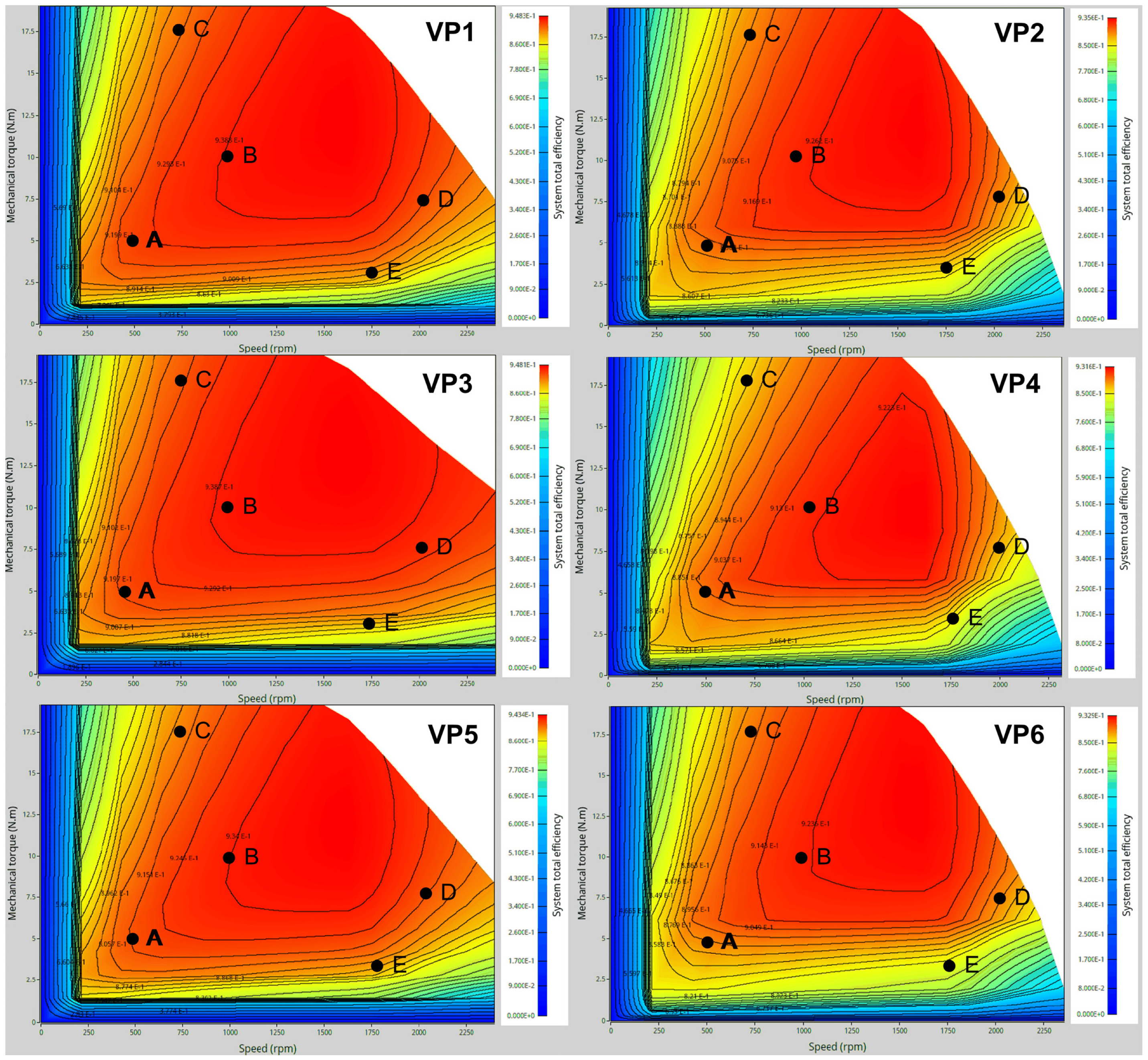
Even though all virtual prototypes have efficiency values over the targeted one, torque–speed–efficiency maps were obtained with the help of FluxMotor software and are presented in Figure 5. Five randomly chosen points (A, B, C, D, E) were considered to compare the efficiency maps. Table 8 shows the values for rotational speed, torque and efficiency corresponding to each point. It can be noticed that VP1 and VP3 have the highest overall efficiency values for the considered points.

4. Conclusions

This paper presents the design and simulation steps required for a 3 kW PMSM motor with two pole pairs to come under the IE4 efficiency class. As it is the result of collaboration between a university and an electrical motor manufacturing company within a research project, the latter imposed the values for the outer stator/inner rotor diameters, and also the type and size of the magnets. Six virtual prototypes were developed and simulated using the Altair FluxMotor software.
The first requirement for all virtual prototypes was to provide the targeted mechanical power (i.e., 3 kW) and consequently the nominal torque of 19.1 Nm. To obtain an efficiency value of at least 90.4% at the nominal operating point, fine changes were made to the geometrical parameters, namely, variations in the stator inner/rotor outer diameters, the stator slot geometry, the wire diameter and the magnets’ distance relative to the rotor outer periphery. Out of the six virtual prototypes, four had an interior PM, one had a V-shaped PM and one a double V-shaped PM. The stack length was adapted to host either three magnets of 35 mm in series (for the first four virtual prototypes), three magnets of 33.5 mm (VP5) or four magnets of 33.5 mm (VP6).
Additional measures were taken to reduce the electromagnetic torque ripple as much as possible through changes in the shape/dimension of the stator slot opening and the magnets’ placement in the rotor. Among the six virtual prototypes, the best overall performance for the nominal operating point was obtained for the versions with 36 stator slots and interior PM (labeled in text as VP2), which reached a nominal efficiency of 94.5% and a torque ripple of 11.61%, along with a reduced total mass (i.e., 17.6 kg). Nevertheless, when analyzing the torque–speed–efficiency maps, the VP1 and VP3 versions had the optimal behavior. Among these latter two, VP1 had lower iron losses (21 vs. 32 W), a lower torque ripple (21.15 vs. 27.87%), a smaller mass (18 vs. 19 kg) and a simpler rotor design.

Author Contributions

C.P.I. prepared the literature studies, was in charge of the design part, analyzed the results and wrote the paper. M.D.C. performed the simulations and revised the paper. I.P. supervised the design part and revised the paper. All authors have read and agreed to the published version of the manuscript.

Funding

This research was funded by Ministerul Cercetării, Inovării și Digitalizării prin Programul Operational Competitivitate, Romania (Ministry of Research, Innovation, and Digitalization through the Operational Program Competitivity, Romania) project “Cresterea competitivitatii Electroprecizia Electrical Motors prin dezvoltarea in parteneriat cu Universitatea Transilvania a unei noi familii de motoare electrice, cu eficienta energetica de clasa superpremium (IE4) (Increasing the competitiveness of Electroprecizia Electrical Motors by developing in partnership with Transilvania University a new electrical motors family with super-premium energetical class (IE4))/121228/POC/163/1/3” (translation from Romanian). The APC was supported by Transilvania University of Brasov.

Institutional Review Board Statement

Not applicable.

Informed Consent Statement

Not applicable.

Data Availability Statement

Not applicable.

Conflicts of Interest

The authors declare no conflict of interest.

References

  1. IEC 60034-30-1:2014; Rotating Electrical Machines—Part 30-1: Efficiency Classes of Line Operated AC Motors (IE Code). International Electrotechnical Commission: Geneva, Switzerland, 2014.
  2. Choi, G.; Jahns, T.M. Reduction of Eddy-Current Losses in Fractional-Slot Concentrated-Winding Synchronous PM Machines. IEEE Trans. Magn. 2016, 52, 1–4. [Google Scholar] [CrossRef]
  3. Wang, Y.; Ma, J.; Liu, C.; Lei, G.; Guo, Y.; Zhu, J. Reduction of Magnet Eddy Current Loss in PMSM by Using Partial Magnet Segment Method. IEEE Trans. Magn. 2019, 55, 1–5. [Google Scholar] [CrossRef]
  4. Denis, N.; Inoue, M.; Fujisaki, K.; Itabashi, H.; Yano, T. Iron Loss Reduction in Permanent Magnet Synchronous Motor by Using Stator Core Made of Nanocrystalline Magnetic Material. IEEE Trans. Magn. 2017, 53, 1–6. [Google Scholar] [CrossRef]
  5. Fang, S.; Liu, H.; Wang, H.; Yang, H.; Lin, H. High Power Density PMSM with Lightweight Structure and High-Performance Soft Magnetic Alloy Core. IEEE Trans. Appl. Supercond. 2019, 29, 1–5. [Google Scholar] [CrossRef]
  6. Jeong, C.-L.; Kim, Y.-K.; Hur, J. Optimized Design of PMSM With Hybrid-Type Permanent Magnet for Improving Performance and Reliability. IEEE Trans. Ind. Appl. 2019, 55, 4692–4701. [Google Scholar] [CrossRef]
  7. Liu, X.; Chen, H.; Zhao, J.; Belahcen, A. Research on the Performances and Parameters of Interior PMSM Used for Electric Vehicles. IEEE Trans. Ind. Elec. 2016, 63, 3533–3545. [Google Scholar] [CrossRef]
  8. Dutta, R.; Pouramin, A.; Rahman, M.F. A Novel Rotor Topology for High-Performance Fractional Slot Concentrated Winding Interior Permanent Magnet Machine. IEEE Trans. Ener. Conv. 2020, 36, 658–670. [Google Scholar] [CrossRef]
  9. Hwang, M.-H.; Han, J.-H.; Kim, D.-H.; Cha, H.-R. Design and Analysis of Rotor Shapes for IPM Motors in EV Power Traction Platforms. Energies 2018, 11, 2601. [Google Scholar] [CrossRef] [Green Version]
  10. Murali, N.; Ushakumari, S.; Mini, V.P. Performance comparison between different rotor configurations of PMSM for EV application. In Proceedings of the 2020 IEEE Region 10 Conference (TENCON), Osaka, Japan, 16–19 November 2020. [Google Scholar]
  11. Jang, H.; Oh, S.-T.; Park, Y.; Kim, H.; Jang, I.S.; Lee, J. Design and Analysis of a Novel Rotor Shape to Improve Power Performance. IEEE Trans. Appl. Supercond. 2020, 30, 1–4. [Google Scholar] [CrossRef]
  12. Thike, R.; Pillay, P. Mathematical Model of an Interior PMSM with Aligned Magnet and Reluctance Torques. IEEE Trans. Transp. Electr. 2020, 6, 647–658. [Google Scholar] [CrossRef]
  13. Puscasu, S.V.; Melcescu, L.; Covrig, M. Cogging Torque Investigation in Permanent Magnet Synchronous Motor Used for Electrical Vehicles. In Proceedings of the 8th International Symposium on Advanced Topics in Electrical Engineering, Bucharest, Romania, 23–25 May 2013. [Google Scholar]
  14. Candelo-Zuluaga, C.; Espinosa, A.G.; Riba, J.-R.; Blanch, P.T. PMSM Design for Achieving a Target Torque-Speed-Efficiency Map. IEEE Trans. Vehic. Tech. 2020, 69, 14448–14457. [Google Scholar] [CrossRef]
  15. Soygenc, O.C.; Ergene, L.T. Particle Swarm Optimization Implementation on PMSM Design. In Proceedings of the 2020 21st International Symposium on Electrical Apparatus & Technologies (SIELA), Bourgas, Bulgaria, 3–6 June 2020. [Google Scholar]
  16. You, Y.-M. Optimal Design of PMSM Based on Automated Finite Element Analysis and Metamodeling. Energies 2019, 12, 4673. [Google Scholar] [CrossRef] [Green Version]
  17. Farshadnia, M.; Cheema, M.A.M.; Pouramin, A.; Dutta, R.; Fletcher, J.E. Design of Optimal Winding Configurations for Symmetrical Multiphase Concentrated-Wound Surface-Mount PMSMs to Achieve Maximum Torque Density Under Current Harmonic Injection. IEEE Trans. Ind. Elec. 2018, 65, 1751–1761. [Google Scholar] [CrossRef]
  18. Edhah, S.O.; Alsawalhi, J.Y.; Al-Durra, A. Multi-Objective Optimization Design of Fractional Slot Concentrated Winding Permanent Magnet Synchronous Machines. IEEE Access 2019, 7, 162874–162882. [Google Scholar] [CrossRef]
  19. Mi, C.C. Analytical Design of Permanent-Magnet Traction-Drive Motors. IEEE Trans. Magn. 2006, 42, 1861–1866. [Google Scholar] [CrossRef]
  20. Boldea, I.; Nasar, S.A. The Induction Machines Design Handbook, 2nd ed.; CRC Press: Boca Raton, FL, USA, 2010; pp. 447–454. [Google Scholar]
Figure 1. The initial geometric dimensions: (a) stator, (b) rotor.
Energies 16 00498 g001
Figure 2. Details of the six considered variants: magnets’ placement (left), stator slot dimensions (center), magnetic flux density distribution (right).
Energies 16 00498 g002
Figure 3. Torque variation.
Energies 16 00498 g003
Figure 4. Cogging torque comparison.
Energies 16 00498 g004
Figure 5. Torque–speed–efficiency maps of the considered virtual prototypes.
Energies 16 00498 g005
Table 1. Design parameters.
Imposed ParametersValueEstimated ParametersValue
Nominal power (Pn)3 kWNominal power factor (cosφn)0.96
Nominal speed (nn)1500 rpmNominal line voltage (Vl)340 V
Nominal efficiency (ηn)0.904Stator inner diameter (Dins)103.6 mm
Stator outer diameter (Douts)169.85 mmNo. of slots24
Rotor inner diameter (Dinr)36 mmAir gap flux density (Bag)0.9 T
Table 2. N42SH magnets’ parameters.
ParameterValue
Residual magnetic flux density Br1300 mT
Normal coercivity Hc1000 kA/m
Intrinsic coercivity Hcj159 kA/m
Magnetic energy density (BH)max334 kJ/m3
Maximum operating temperature T150 °C
Dimensions (L × l × h)35 mm × 26 mm × 4 mm
Magnet volume Vm3.64 cm3
Table 3. Stator coil’s design.
ParameterValue
Pole pitch (τ)81.37Calculated
Pole spanning coefficient (αi)0.725Chosen
Air gap flux density (Bag)0.9 TImposed
Pole flux (Φ)5.57 mWbCalculated
Number of turns per phase (W1)230Calculated
Number of current paths in parallel (a1) 1Chosen
Number of conductors per slot (nc)57Calculated
Specific stator current load (A1)24 A/cmCalculated
Wire current density (J1)6 A/mm2Chosen
Wire cross-section (Ac1)0.95 mm2Calculated
Wire gauge diameter (dc1)1.1 mmCalculated
Table 4. Stator slot design.
ParameterValue
Useful slot area (Asu)133 mm2Calculated
Slot fill factor (kfill)0.4Chosen
Tooth flux density (Bts)1.6 TChosen
Back core flux density (Bcs)1.5 TChosen
Stator slot pitch (τs)12.17 mmCalculated
Table 5. Optimized geometrical parameters.
ParameterVP1VP2VP3VP4VP5VP6
Stator outer diameter (mm)169.85169.85169.85169.85169.85169.85
Stator inner diameter (mm)97.899.0111.6108.2107.6113.3
Rotor outer diameter (mm)95.697.8110.0106.2106.0109.0
Rotor inner diameter (mm)363636363636
Stack length (mm)105105105105101.25135
Stator slots number243624242436
Rotor pole pairs222222
PM volume (cm3)87.3687.3687.36174.72105.7140.9
Table 6. Stator winding parameters.
VP1VP2VP3VP4VP5VP6
Stator slots number243624242436
Slot net area (mm2)81.6826.998.8352.2773.7134.51
Number of conductors per slot525252525252
Wire gauge diameter (mm)2 × 11 × 0.82 × 1.12 × 0.82 × 0.952 × 0.65
Number of current paths121112
Phase resistance at 20 °C (Ω)0.871.360.751.361.281.36
Slot filling factorGross (%)60.740.962.833.449.938.4
Net (%)72.951.174.241.960.550.6
Table 7. Performance parameters.
VP1VP2VP3VP4VP5VP6
Efficiency (%)95.794.595.893.795.294.5
Iron losses (W)213432262545
Torque ripple (%)21.1511.6127.8719.0329.747.53
Total motor mass (kg)1817.6191617.522
Table 8. Efficiency maps’ comparison.
PointParametersEfficiency (%)
Speed (rpm)Torque (Nm)VP1VP2VP3VP4VP5VP6
A5004.9592.288.39289.491.588.6
B1000109492.29491.693.492
C75017.59188.891.885.79088.9
D20007.59288.893.188.290.588.7
E1750389.186.188.285.788.782.5
Disclaimer/Publisher’s Note: The statements, opinions and data contained in all publications are solely those of the individual author(s) and contributor(s) and not of MDPI and/or the editor(s). MDPI and/or the editor(s) disclaim responsibility for any injury to people or property resulting from any ideas, methods, instructions or products referred to in the content.

