
Overview of the M-Cycle Technology for Air Conditioning and Cooling Applications


1
Department of Power Engineering, Cracow University of Technology, Al. Jana Pawla II 37, 31-864 Cracow, Poland
2
Department of Thermal Processes, Air Protection and Waste Utilization S-5, Cracow University of Technology, ul. Warszawska 24, 31-155 Cracow, Poland
*
Author to whom correspondence should be addressed.
Energies 2022, 15(5), 1814; https://doi.org/10.3390/en15051814
Submission received: 31 January 2022
/
Revised: 23 February 2022
/
Accepted: 24 February 2022
/
Published: 1 March 2022
(This article belongs to the Special Issue Research and Development on Indirect Evaporative Cooling Technology)
Abstract
:The indirect evaporative cooler (IEC) has excellent potential to replace or improve conventional vapor compression equipment in HVAC and refrigeration applications. This could be achieved by using the M-cycle (dew-point evaporative cooling technology). This thermodynamic concept makes it possible to derive a large amount of energy from the air stream (as latent heat released during water evaporation into the working air stream) and use it for another air stream (product). Its application has also spread to other sectors, such as water desalination and distillation, power plants, or NOx reduction. This paper provides an overview of the M-cycle mainly in air conditioning (MAC, D-MAC, H-MAC) and refrigeration (MCT, M-condenser). Various integrated solutions are described, showing improved effectiveness in terms of the wet-bulb temperature and the dew point. The design features of consolidated solutions are better In terms of the flow distribution, geometry, or volume. Most of the improvements confirm the great potential of the M-cycle to increase the unit or the system efficiency due to lower energy and water consumption.
1. Introduction
Energy consumption in the 21st century is becoming a challenge due to climate changes and growing population. In terms of the average ambient temperature, each successive year is usually warmer than the previous one. According to Polish Energy Market Agency [1], about 40% of energy in Poland is used for industrial processes, half of which is used for thermal processes. This study also takes account of the impact of commercial and domestic HVAC systems. The HVAC market is growing, aiming to ensure a comfortable environment for customers in terms of cooling, heating, and air preparation in ventilation systems. In some developed countries, such as Japan, the USA, or Korea, more than 90% of households are equipped with individual air conditioning (AC) systems (cf. Figure 1). These devices are responsible for about 25% of the total energy consumption in Europe [2] and 15% worldwide [3]. The problem is that consumers do not always consider the most efficient AC units. Most decisions to choose an AC unit are solely price-based. Investing in more efficient HVAC equipment could reduce future energy demand by 45% in 2050 [4].
Most modern heating, ventilation, air-conditioning, and process cooling units are based on vapor compression. This solution requires a significant amount of electricity and increases global warming due to the use of harmful refrigerants. The climate change prompts leading HVAC equipment manufacturers to search for more efficient and ecological solutions. Available power is not limitless. It is constrained by the physics and technology of compressors and heat exchangers. Several environmentally friendly refrigerants with low global warming potential (GWP) and ozone depletion potential (ODP) factors are known that can be used in the refrigeration cycle to minimize harmful effects on the environment [5]. Refrigerants such as ammonia NH3 (GWP = 0, ODP = 0), carbon dioxide CO2 (GWP = 0, ODP = 1), or propane (R290, GWP = 0, ODP = 3) are the future of modern industrial-sized HVAC units. Unfortunately, each of them is characterized by toxicity, flammability, or high operating pressures, which limits their applicability on a medium or industrial scale. For example, ammonia cannot be used in home air conditioners or heat pumps because potential leaks might harm residents. The second reason is that ammonia is highly corrosive to copper, and this material is most commonly used in refrigeration due to its very good thermal conductivity. In turn, a system using CO2 requires more durable equipment, as the operating pressure of carbon dioxide is significantly higher compared to other refrigerants. In addition, due to the low critical temperature of CO2, which is +30.9 °C, the refrigeration unit must operate under transcritical conditions to function properly and transfer heat. Propane, on the other hand, is highly explosive and all equipment in which it is used must be of a special class, or the quantity of this refrigerant must be kept within an appropriate minimum [6,7,8].
A neutral and pure refrigerant is water (H2O), which could be used more widely. Marked as R718, it has unique properties (GWP = 0, ODP < 1). Water can be used as a primary or a secondary refrigerant. This natural liquid is one of the most powerful refrigerants due to the energy concealed in evaporation—2200 kJ of heat can be obtained from one kilogram of evaporating water. No other refrigerant has such high heat of vaporization. The utilization of the heat of water vaporization has its roots in ancient times, when people prepared food in porous vessels where water could evaporate through the surface of the walls. Natural draught then enhanced the heat transfer [9,10].
Evaporative technologies make it possible to achieve air temperature below the ambient temperature. This powerful natural effect can improve any cooling system to achieve greater efficiency and more stability even in the highest ambient temperatures and, most importantly, lower power consumption. Due to that, evaporative systems have gained more interest economically and ecologically. Two evaporative systems can be distinguished and Figure 2 shows the difference between DEC and IEC:
- Direct evaporative coolers (DEC).
- Indirect evaporative coolers (IEC).
Figure 2.
Principle of operation of standard evaporative cooling techniques [11]: (a) DEC, (b) IEC.
Figure 2.
Principle of operation of standard evaporative cooling techniques [11]: (a) DEC, (b) IEC.
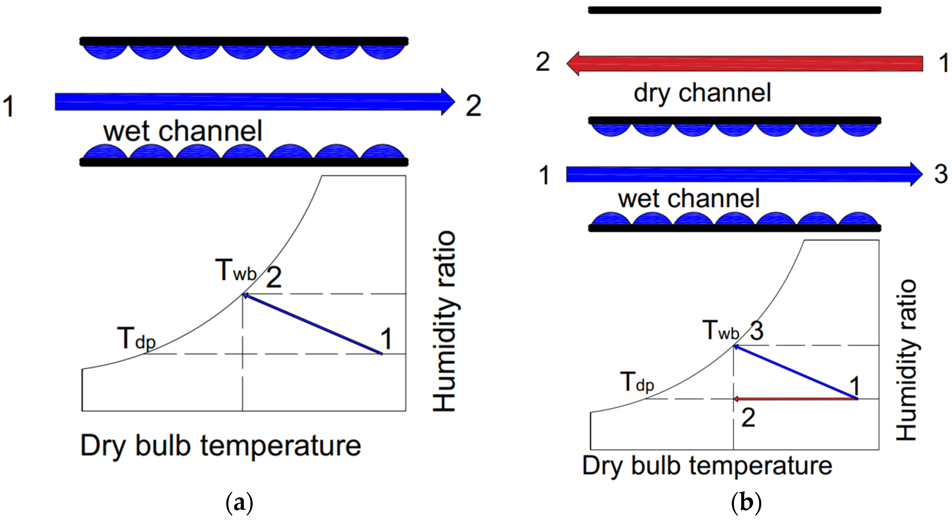
Unlike vapor compression, evaporation systems are innovative and treated as a low-cost cooling technique. Similar to all working units, they have their limitations. The limits are thermodynamic and refer to the wet-bulb temperature, which is the lowest temperature achieved by evaporating water. The wet-bulb temperature depends on the dry-bulb temperature and relative humidity. This relationship is shown in Figure 3. The solution which has fewer limitations than evaporative cooling is the M-cycle. In this case, the lowest possible temperature is the dew point, when the air is saturated and water condensation occurs. This is why the M-cycle is also known as the dew-point cooling technology.

2. M-Cycle Principle of Operation
The M-cycle was conceived by scientists from the Soviet Union, especially by Valeriy Maisotsenko. The first patent was filed in 1976 (patent numbers SU979796 and SU620745). Since then, many new applications have been submitted by many scientists from all over the world. There have been many more patents issued since then [11].
The principle of operation of the M-cycle is based on the heat and mass transfer between two air streams. One is the dry air stream, or the product. The other is the wet air stream, referred to as the working stream. The Maisotsenko cycle is based on the thermodynamic process of absorbing energy in the form of latent heat released during water evaporation from the wet stream of air. Inlet air is divided into two paths. The product, the air that will be cooled to cool a reservoir, flows through dry channels. The working stream will flow in wet paths, evaporating and dissipating energy from the product. On the market there are solutions commercialized by the Coolerado Corporation [15,16]. Apart from air cooling systems, there are a few other potential applications of the M-cycle, which are as follows:
All the above-mentioned processes occur in cross-flow heat and mass exchangers (HMXs). The described phenomena make it possible to achieve temperatures even below the wet-bulb point. In the best conditions it is possible to achieve the air outlet temperature close to the dew point. Another benefit is that the product stream does not change its humidity, which could be an advantage for any application where the cooled space humidity is a crucial factor. The fact that the supply moisture content can be kept unchanged makes IEC systems more suitable for domestic applications. The HMX structure is schematically shown in Figure 4 [22].
As described in [23,24], the quality criteria of the M-cycle heat and mass exchanger can be defined by the three factors presented below. These factors can also be used to prepare an optimization process:
- Dew-point thermal effectiveness—the ratio of the difference between the primary flow inlet and outlet temperatures to the difference between the primary flow inlet and outlet dew-point temperatures [25]:
—cooling capacity
is the volume of the HMX structure in m3, which should be calculated as
- Theoretical coefficient of performance (COP)—calculated as the ratio between cooling capacity and the fan energy consumption [26]:
N is the fan theoretical power, which can be expressed as
The above correlations are presented in Figure 5 below and in [27], where the M-cycle was optimized.
Excluding air cooling systems, there are a few other potential applications of M-cycle. Water desalination and distillation [17,18] is one of most important. Estimated annual energy consumption of world desalination processes is 75.2 TWh. By the year 2050, it is projected that water consumption will increase to over 60 billion m3 [28]. In work [29] presented by Tariq et al., a novel air saturator (based on M-cycle) was used as a humidifier in a desalination plant. The analysis was carried out for 31 cities with a water shortage. The proposed M-cycle-based configuration has better performance (USD 0.03/liter) and water production rates (over 30% more) than conventional desalination plants. Reduction is around 14% compared to conventional direct-contact humidifier-based desalination system. Consequently, around 7.1% less CO2 will be generated into the atmosphere. The best performance was obtained for hot and dry conditions, based on Köpen classification [30].
Power generation plants or NOx reduction are other applications where M-cycle could be used [19,20,21]. An M-cycle-based air saturator simplifies the humidification process of the combustion air in a gas turbine cycle. The turbine exhaust gas is used to humidify the pressurized air. With this, thermal energy is recovered. The turbine power efficiency is also improved, as well as the cycle efficiency. Economic and sensitivity analyses were reported [31]. The numerical results showed around 4% of improvements in system efficiency. Consequently, the same NOx was obtained [32].
3. M-Cycle HVAC Systems
One of the first IEC patents was issued in 1906 [33], which laid the foundation for future evaporative solutions. The M-cycle was invented fifty years ago and revolutionized the IEC market, but it still was not investigated or described extensively. It has drawn increasing attention since 2012, and this trend can be observed in Figure 6 [34]. Before 2012, there were only a few articles and studies describing these phenomena.
The above-mentioned M-cycle applications and solutions in air cooling have been studied and optimized, both experimentally and numerically. The authors of the works considered several dry or humid cities and countries around the world, for example:
- Arab Gulf cities (numerical studies of the dew-point indirect evaporative cooler (DPIEC)) [35].
- Riyad, South Arabia (numerical studies of the DPIEC [36].
- Martos, Spain (experimental studies of the solar desiccant cooling system) [37].
- Beijing, China (numerical studies of a DPIEC with a heat and mass exchanger) [38].
- North Italy (numerical and partial experimental studies of the DPIEC) [39].
- Bushehr, Iran (numerical studies of the solar desiccant cooling system) [40].
3.1. Maisotsenko Air Conditioning (MAC)
It can be seen that the M-cycle and IECs are becoming more important nowadays. New applications appear. Researchers have also found an innovative configuration of the HMX that enhances efficiency and makes it possible to achieve a lower temperature of the leaving air product stream. This creates an opportunity for more potential applications for a broad variety of locations and conditioned spaces. A few M-cycle configurations are shown in Figure 7 [41].
These solutions can work as standalone systems or co-operate with other structures, such as membranes, the desiccant wheel, hybrid configurations, ejectors, M-cooling towers, or M-condensers. Each solution has its limitations and specific operating conditions [42].
Khandelwal et al. [43] investigated annual energy consumption of three different HVAC systems. The considered AC systems were a chiller, a chiller coupled with evaporative cooling, and a chiller coupled with regenerative evaporative cooling. In the second system, annual air conditioning savings total 17%, and in the third, they exceed 22%. A DPIEC system for an office building was also investigated by Costelloe et al. [44]. They found that evaporative cooling only could be used for the whole year, without switching on any vapor compression units. This study was conducted for the temperate climate of the regions of Dublin and Milan. Public buildings in Teheran were investigated by Heidarinejad et al. in [45]. The authors applied a two-stage indirect/direct evaporative cooling system. The research results indicate that such systems could be an alternative solution for the vapor AC unit. Energy will be minimized; however, water consumption will be higher by 55% compared to DEC.
Lin et al. [46] fabricated a DPEC with cross flow to check its performance and power efficiency on different climates. The system composes of 12 channels (wet and dry). Each channel had a length of 22 mm and width of 3 mm. Ambient air temperature and humidity were +30 °C and 67%. The results which were obtained show that the mean outlet air temperature is +25.5 °C. The wet-bulb effectiveness reached about 86% with COP equal to 4.6 [46]. Aluminum fins, in dry channels, to improve heat transfer were added by Ali et al. [47]. The results conclude that cooling capacity of the system could be improved by 18%. Khalid et al. [48] assessed a cross-flow DPEC system with 35 aluminum layers for Pakistan. The results conclude that dew-point effectiveness (range: 62–85%) is greater than wet-bulb effectiveness (range: 92–120%). However, the paper shows that this system is only suitable for smaller HVAC applications. The experimental results, presented by Anisimov et al. [24] and Pandelidis et al. [49], confirm air inlet and outlet temperature alterations when humidity increases from 11 g/kg to 25 g/kg. Respectively, ranges of temperature are 17–30 °C and 5.2–20.1 °C. Moreover, the dew-point and wet-bulb effectiveness vary between 15–78% and 85–115%, respectively.
Despite that the DPEC with cross-flow configuration could lower outlet air temperature and increase cooling performance, research concludes that it also has some demerits. The cooling capacity depends on the air humidity. If air humidity ratio is above comfortable level, cooling capacity drops. In addition, low cooling effectiveness reduces air flow and system size. Furthermore, the working air stream could not fully exchange the heat as it is transferred to wet channels to early.
To eliminate the drawback of DPEC cross-flow DPEC, counter flow could be ap-plied. It could improve cooling effectiveness of the system, which was confirmed by detailed reviews. New configurations were presented by Lin et al. [50]. Authors investigated the system made of five pairs of wet and dry channels. A year later, Lin et al. [51] implemented steady-state and transient-state analyses on the cooling performance of a DPEC counter-flow system to utilize the influence of water temperature and distribution in channels. Proper water management is crucial, and it could disrupt its distribution, affecting air temperature. Pakari et al. [52] performed an experimental and numerical study of counter-flow DPEC, and 1D and 3D heat and mass transfer models were presented. The performance prediction model was established. The results were accurate at 10% (1D) and 8.5% (3D). The calculated wet-bulb efficiency was 120%. In a paper presented by Moshari et al. [53], an analytical solution was presented. Authors obtained minimalization of pressure drop in IEC. The numerical simulation showed increase of power consumption with a fin height increment. Wan et al. [54] prepared an analysis of counter-flow DPEC with two configurations (A: parallel and B: counter) of water film flow distribution referring to air stream. The two-dimensional computational fluid dynamics model was developed. The results showed that configuration B has better cooling effectiveness than configuration A. The wet-bulb and dew-point effectiveness reached 110% and 78%, respectively.
3.2. Desiccant M-Cycle Air Conditioning (D-MAC)
Desiccant air conditioning (DAC) systems are among the most promising solutions to improve standard air conditioning units with vapor compressors. The typical solution is shown in Figure 8, which combines different kinds of heat exchangers. A desiccant wheel dehumidifies the ambient airflow. A rotary heat exchanger precools the dehumidified air stream. At the end of the system there is a spray chamber where the air temperature is lowered, and the air becomes moister through evaporative cooling. DAC provides standard indoor conditions for residents. Exhaust air returns to the spraying chamber, where it is also cooled and humidified. This process enhances the effectiveness of heat recovery in the rotary exchanger. Air has to be heated to regenerate the desiccant wheel. Heating occurs in solar panels or by electric heaters [55].
DAC has two main disadvantages. One is direct evaporative cooling, by which moisture is added to the air. In DEC, the limitation is the wet-bulb temperature (wet-bulb effectiveness), which is almost impossible to reach by typical direct cooling. Another disadvantage is the size of the system. Both the rotary exchanger and the spraying chamber need significant volumes [44].
Eliminating the limitations mentioned above increases the DAC system applicability. Such research was conducted by a few authors, e.g., She et al. [56]. The analyses concerned DAC with air precooling with vapor AC. Chen et al. [57] analyzed a few materials of the desiccant wheel to decide which composition of silica, gel, and polyacrylates was the most effective in moisture absorption. They found the proportion of 10 to 1 to 1 to be the most effective, with a 40% higher sorption capacity [58].
The solution proposed by Pandelidis et al. in [58] combines standard DAC with the M-cycle (D-MAC). The idea is illustrated in Figure 8. The effectiveness of DAC can be enhanced by different types of the M-cycle, which are presented in Figure 9. The size issue is resolved by replacing the rotary exchanger and the spraying chamber with a heat and mass exchanger (HMX) with a much smaller volume.
The numerical simulations based on the NTU model and described in [58] were compared to experimental data. The analyzed systems were checked under several conditions to achieve the most reliable results, indicating that all the three solutions could achieve satisfactory temperatures of the product air, close to the dew point. Each solution has its advantages and disadvantages. For example, the regenerative system (Cycle 1) is very sensitive to the airflow ratio, the system with a cross-flow M-cycle HMX (Cycle 2) is sensitive to ambient humidity, while the system with a standard cross-flow HMX (cycle 3) is sensitive to the conditioned space heat loads [58].
Cycle 2 is the most complicated solution, but it makes it possible to achieve the lowest air temperatures and the highest cooling capacities. Cycle 3 is the simplest one, but its application is only for spaces where low latent heat loads appear. Cycle 1 could be an alternative for Cycle 3 because it is not sensitive to heat loads, but this system achieved lower efficiencies in many cases. On the other hand, Cycle 1 is simpler and cheaper than Cycle 2, but more complex than Cycle 3. To select the best solution, the analysis has to take account of a few factors, such as the facility type, the energy price, the available space, and others.
3.3. Hybrid M-Cycle Air Conditioning (H-MAC)
H-MAC combines MAC and the vapor compression cycle. Such a configuration is shown in Figure 10. The study presented in [59], of a rooftop application, indicates that H-MAC needs around 80% less energy than a typical AC system. Such significant energy savings could be achieved due to the precooling of air entering the evaporator when saturated warm air from the system wet channels flows to the condenser. In [60], a particular H-MAC design was simulated numerically. The authors proposed a new design. The main change was to mix the return air from the air-conditioned rooms with the supply air. The simulations were carried out for hot and humid cities. The results show that this solution could bring significant energy savings in cases where MAC is used as a standalone cooling system for 40–47% of the operating time [11].
4. M-Cycle Cooling
4.1. M-Cooling Tower (MCT)
The capabilities of the M-cycle are much broader compared to air cooling (IEC). It can also be used to cool water, as illustrated in Figure 11, where the distribution of the air and the water temperature in the HMX channels is shown. It can be seen that the water temperature at the end of the channels is lower than the air temperature. Figure 11 also presents the MCT diagram proposed in [61]. In their study, Pandelidis et al. made a mathematical (one-dimensional NTU model) evaluation of the processes occurring in the MCT. It was based on the methodology presented by Anisimov in [62].
The results of this study are promising, even though the model is based on the assumption that the heat and mass transfer is realized under steady-state conditions. Air is an ideal incompressible gas, and the kinetic properties (for water and air) are stable. Consequently, the water temperature obtained at the outlet is lower than the wet-bulb temperature (Twb = 19.9 °C), totaling 18 °C. It was possible to reduce the water temperature by 2 °C as the air was precooled in the dry channels and had the temperature of 16.1 °C at the end [47].
The large-scale cooling tower used in most power plants around the world was investigated in [63]. It is clearly demonstrated that incorporating the M-cycle into a natural draft cooling tower (NDCT), which will involve small internal changes as shown in Figure 12, will increase the efficiency of power stations working in the Rankine cycle.
Considering the dry-bulb temperature of +30 °C, relative humidity of 35%, and the power station capacity of 500 MWt, the NDCT will reduce the water temperature from 38 °C to 24 °C. The water outlet temperature can be reduced to approx. 13 °C by using the Maisotsenko effect. Consequently, the water mass flow rate will be reduced by 44%, while the make-up water mass flow rate will be smaller by 20% [63].
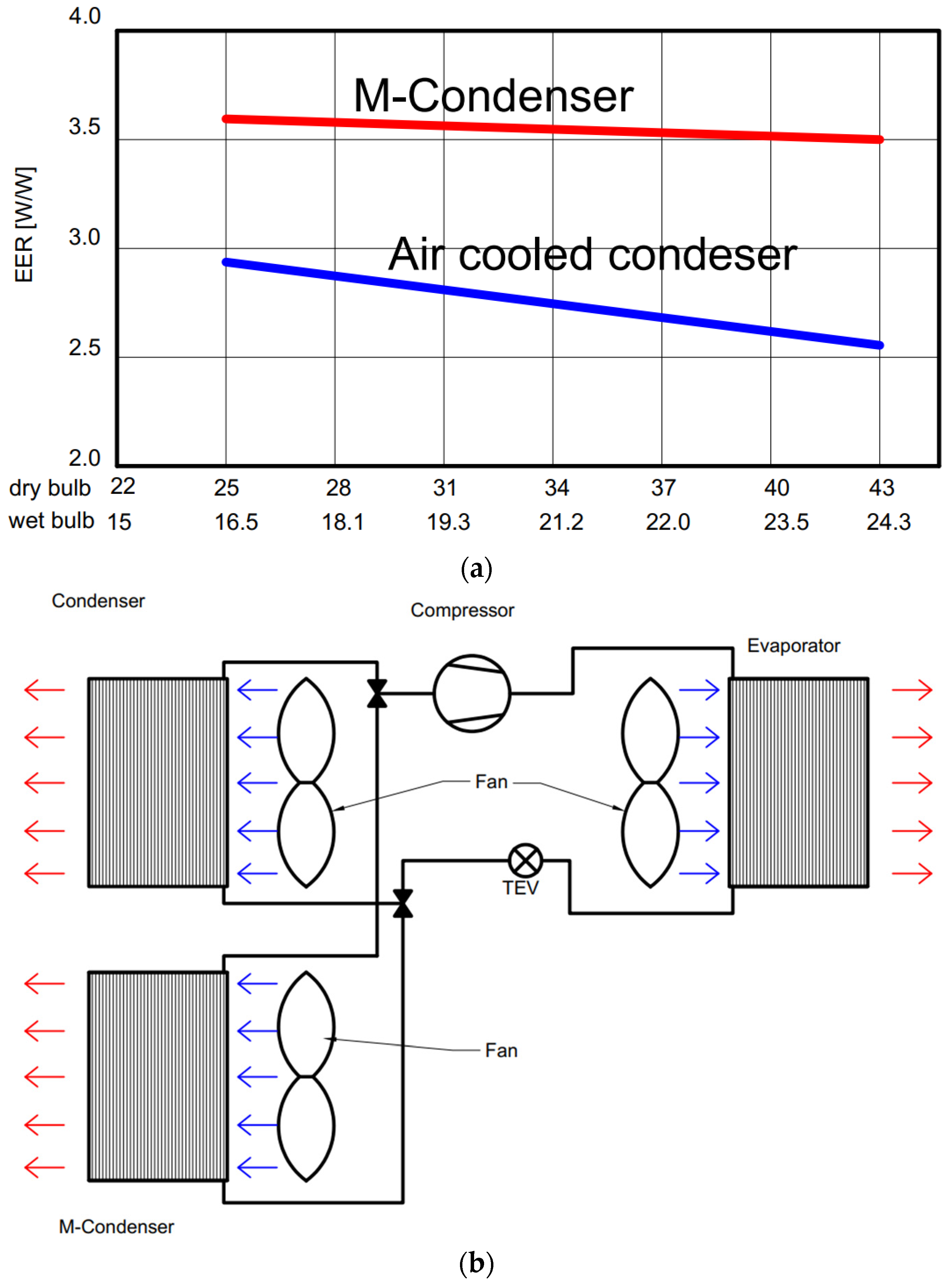
4.2. M-Condenser
One of the most important vapor compression units is a condenser that dissipates heat into the environment or into another medium (glycol, water, etc.). Therefore, a distinction can be made between an air-cooled condenser, a water-cooled condenser, or an evaporative condenser. In the case of an evaporative condenser, less energy consumption can be expected, with continuous water consumption. Combining an air-cooled condenser with the Maisotsenko effect will enhance heat rejection, causing a reduction in the consumption of energy and water. An experimental study of the M-condenser was carried out by Gillan et al. [64]. The results are shown in Figure 13a, and they were reproduced in [11]. It can be seen that the M-condenser achieves bigger EER values (30% higher on average). The investigated system is presented in Figure 13b. The condenser was a typical microchannel solution where the HMX was made of cellulose sheets [11].
5. Discussion
The literature review shows a clear trend towards an increased use of the M-cycle in air conditioning systems. Many researchers and authors try to apply the M-cycle in existing HVAC solutions. Due to that, the wet-bulb and the dew-point effectiveness and the cooling unit structure can be improved. Some of the authors focus on improving water and energy consumption (air distribution inside the HMX). In a few works, the authors perform experimental studies of different variants of the exchanger geometry. Antonellis et al. [65] proposed a different IEC geometry and flow distribution. They achieved the wet-bulb effectiveness of around 53%. Xu et al. in [66] applied a layer of super-hydrophilic material. Due to that, the dew-point effectiveness reached 75%, and the wet-bulb effectiveness was around 115%. Different water spraying arrangements were tested by Al-Zubaydi et al. [67]. Several water spraying methods made it possible to significantly improve the performance of the IEC system [24].
Another possibility to improve the IEC performance is to carry out single- or multi-objective optimization. For example, the results presented by Jafarian et al. [68] showed optimization of the channel length and gap and of the inlet air velocity for different climatic conditions. Golizadeh et al. [69] considered cooling efficiency and established the cooler construction costs.
The M-cycle applications for air conditioning and cooling are well known. The M-cycle should also be used in different industry sectors to enhance efficiency. Recent examples include applications in gas turbine cycles such as the M-HAT (Maisotsenko air turbine cycle), the M-SAB (Maisotsenko sub-atmospheric Brayton cycle), and the M-ABC (Maisotsenko air bottoming cycle) [11]. Each of the above-mentioned cycles achieved higher thermodynamic efficiency, or it was possible to recover significantly more heat [11]. Another interesting application described by Pandelidis et al. [17] is water desalination with the use of a multistage regenerative counter-flow dew-point exchanger. This configuration enables production of pure water. However, it has its limitations, which requires more research and development.
Efforts are made to find a more economical and sustainable solution to ensure production of cooled air in a possibly simple and effective way. The DPIEC still needs improving to increase its applicability. The DPIEC has achieved more significant savings in hot and dry climates. The dew-point cooler could also be used in a humid or temperate climate but needs support, e.g., by the desiccant wheel or a typical vapor compression system. These systems are more complex but also achieve good results. Researchers should also spend more effort on improving the HMX geometry, structure, and quality of air and water distribution.
6. Challenges and Drawbacks
The present study can conclude that regardless of extended research and development on IEC, scientists may face some challenges:
- Improvement of water and air distribution inside channels.
- Developing of new materials dedicated for IEC for greater heat and mass transfer, less pressures drops and better applicability.
- Looking for novel solutions and connect with IEC to increase efficiency of systems. For example, applying novel bare tube plastic heat exchanger (BTHX) to D-MAC. The asymmetry tube geometry shows better heat transfer performance [70].
- Conducting further studies and research on increasing the thermal COP.
- Simplification of the system. The evaporative cooling systems are more complicated and occupy more space than conventional HVAC machines.
- Optimize construction costs, keeping the cooling efficiency at high level.
7. Conclusions
This literature review provides the overview of Maisotsenko cycle and its applicability in various applications. The study concludes the following:
- The standalone MAC can provide thermal comfort for inhabitants when air humidity is not very high.
- For more humid regions, some modifications and design variations are discussed to achieve proper air-conditioning cooling load.
- D-MAC enables a significant energy saving in humid regions.
- Unlike standard cooling towers, the M-cooling tower has greater COP.
- The M-condenser could enhance dissipation of the heat load of the system compared to evaporative condensers.
- Application of the Maisotsenko cycle for power generation plants improves thermodynamic efficiency of the cycle with NOx reduction.
- Experimental studies on several M-cycle application, (HVAC, cooling, power plants, desalination, etc.) are still limited.
- The interest in M-cycle solutions should be stimulated in future to obtain new applications.
Author Contributions
Conceptualization, J.T. and B.J.; methodology, M.J.; investigation, B.J.; writing—original draft preparation, B.J.; writing—review and editing, J.T. and M.J. All authors have read and agreed to the published version of the manuscript.
Funding
This research received no external funding.
Institutional Review Board Statement
Not applicable.
Informed Consent Statement
Not applicable.
Data Availability Statement
Not applicable.
Conflicts of Interest
The authors declare no conflict of interest.
Nomenclature
| AC | Air conditioning |
| BTHX | Bare tube plastic heat exchanger |
| cp | Specific heat capacity (J/(kgK)) |
| CO2 | Carbon dioxide as refrigerant |
| COP | Coefficient of performance |
| DEC | Direct evaporative cooler |
| DPEC | Dew point evaporative cooler |
| DPIEC | Dew-point indirect evaporative cooler |
| D-MAC | Desiccant M-cycle air conditioning |
| EER | Energy efficient ratio |
| G | Mass flow of moist air (kg/s) |
| GWP | Global warming potential |
| h | Height (m) |
| HMX | Heat and mass exchanger |
| HVAC | Heating, ventilation and air conditioning |
| H-MAC | Hybrid M-cycle air conditioning |
| IEC | Indirect evaporative cooler |
| Lx | Cooler length stream-wise (m) |
| Ly | Channel width (m) |
| MAC | Maisotsenko air conditioning |
| MCT | M-cooling tower |
| M-HAT | Maisotsenko air turbine cycle |
| M-SAB | Maisotsenko sub-atmospheric Brayton cycle |
| M-ABC | Maisotsenko air bottoming cycle |
| N | theoretical fan power (W) |
| NDCT | Natural draft cooling tower |
| NH3 | Ammonia as refrigerant |
| ODP | Ozone depletion potential |
| Q | Cooling capacity (W) |
| R290 | Propane as refrigerant |
| R718 | Water as refrigerant |
| RH | Relative humidity (%) |
| T | Temperature (°C) |
| TEV | Thermo expansion valve |
| VHMX | HMX structure volume (m3) |
| W | Heat capacity rate of the fluid (W/K) |
| ∆p | Pressure drop (Pa) |
| Special characters | |
| δ | Thickness (m) |
| ε | Effectiveness (-) |
| Subscripts | |
| 1 | Inlet parameters of primary flow or secondary |
| 2 | Outlet of primary |
| 3 | Outlet of secondary |
| db | Dry-bulb temperature |
| dp | Dew-point temperature |
| wb | Wet-bulb temperature |
| IN | Inlet |
| OUT | Outlet |
| plt | Channel plate |
| product | Reference to product air stream |
| work | Reference to working air stream |
References
- Energy Market Agency S.A, Statistics Poland, Enterprises Department. Consumption of Fuels and Energy Carriers in 2019; Energy Market Agency: Warsaw, Poland, 2020.
- De Angelis, A.; Chinese, D.; Saro, O. Free-cooling potential in shopping mall buildings with plants equipped by dry-coolers boosted with evaporative pads. Int. J. Heat Technol. 2017, 35, 853–863. [Google Scholar] [CrossRef]
- Fan, Y.; Luo, L.; Souyri, B. Review of solar sorption refrigeration technologies: Development and applications. Renew. Sustain. Energy Rev. 2007, 11, 1758–1775. [Google Scholar] [CrossRef]
- IEA. The Future of Cooling. Available online: https://www.iea.org/reports/the-future-of-cooling (accessed on 19 April 2021).
- BITZER Kuehlmaschinenbau GmbH. Refrigerant Report 20; A-501-20 EN. Available online: https://www.bitzer.de/gb/en/ (accessed on 19 April 2021).
- Yanga, Z.; Feng, B.; Ma, H.; Zhang, L.; Duan, C.; Liu, B.; Zhang, Y.; Chen, S.; Yang, Z. Analysis of lower GWP and flammable alternative refrigerants. Int. J. Refrig. 2021, 126, 12–22. [Google Scholar] [CrossRef]
- Artusoa, P.; Marinetti, S.; Minetto, S.; Del Col, D.; Rossetti, A. Modelling the performance of a new cooling unit for refrigerated transport using carbon dioxide as the refrigerant. Int. J. Refrig. 2020, 115, 158–171. [Google Scholar] [CrossRef]
- Longo, G.; Mancin, S.; Righetti, G.; Zilio, C. Hydrocarbon refrigerants HC290 (Propane) and HC1270 (Propylene) low GWP long-term substitutes for HFC404A: A comparative analysis in vaporisation inside a small-diameter horizontal smooth tube. Appl. Therm. Eng. 2017, 124, 707–715. [Google Scholar] [CrossRef]
- Bruno, F. On-site experimental testing of a novel dew point evaporative cooler. Energy Build. 2011, 43, 3475–3483. [Google Scholar] [CrossRef]
- Saman, W. Developments in evaporative and desiccant cooling systems and their potential application in Australia. In Proceedings of the Fifth Australian Heat and Mass Transfer Conference, Brisbane, Australia, 6–9 December 1993. [Google Scholar]
- Mahmood, M.; Sultan, M.; Miyazaki, T.; Koyama, S.; Maisotsenko, V. Overview of the Maisotsenko cycle—A way towards dew point evaporative cooling. Renew. Sustain. Energy Rev. 2016, 66, 537–555. [Google Scholar] [CrossRef]
- Ashrae Climatic Design Conditions 2009/2013/2017. Available online: http://ashrae-meteo.info/v2.0/ (accessed on 19 April 2021).
- Meteonorm Database, Meteotest AG Fabrikstrasse 14, 3012 Bern, Schweiz. Available online: https://meteonorm.com/ (accessed on 19 April 2021).
- Free Online Interactive Psychrometric Chart Flycarpet. Available online: http://www.flycarpet.net/en/PsyOnline (accessed on 20 April 2021).
- Coolerado Corporation. Available online: http://www.coolerado.com/ (accessed on 19 April 2021).
- U.S. Department of Energy. Coolerado Cooler Helps to Save Cooling Energy and Dollars. 2007. Available online: https://www.nrel.gov/docs/fy07osti/40041.pdf (accessed on 1 January 2022).
- Pandelidis, D.; Cichoń, A.; Drąg, M.; Worek, W.; Cetin, S. Water desalination through the dewpoint evaporative system. Energy Convers. Manag. 2021, 229, 113757. [Google Scholar] [CrossRef]
- Buyadgie, D.; Buyadgie, O.; Drakhnia, O.; Brodetsky, P.; Maisotsenko, V. Solar low-pressure turbo-ejector Maisotsenko cycle-based power system for electricity, heating, cooling and distillation. Int. J. Low-Carbon Technol. 2015, 10, 157–164. [Google Scholar] [CrossRef] [Green Version]
- Jenkins, P.; Cerza, M.; Saaid, M. Analysis of using the M-cycle regenerative humidification process on a gas turbine. J. Energy Power Eng. 2014, 8, 1824–1837. [Google Scholar]
- Saghafifar, M.; Gadalla, M. Innovative inlet air cooling technology for gas turbine power plants using integrated solid desiccant and Maisotsenko cooler. Energy 2015, 87, 663–677. [Google Scholar] [CrossRef]
- Saghafifar, M.; Gadalla, M. Analysis of Maisotsenko open gas turbine power cycle with a detailed air saturator model. Appl. Energy 2015, 149, 338–353. [Google Scholar] [CrossRef]
- Rogdakis, E.; Tertipis, D. Maisotsenko cycle: Technology overview and energy-saving potential in cooling systems. Energy Emiss. Control. Technol. 2015, 3, 15–22. [Google Scholar]
- Anisimov, S.; Pandelidis, D.; Danielewicz, J. Numerical study and optimisation of the combined indirect evaporative air cooler for air-conditioning systems. Energy 2015, 80, 452–464. [Google Scholar] [CrossRef]
- Anisimov, S.; Pandelidis, D.; Jedlikowski, A.; Polushkin, V. Performance investigation of a M (Maisotsenko)-cycle cross-flow heat exchanger used for indirect evaporative cooling. Energy 2014, 76, 593–606. [Google Scholar] [CrossRef]
- Duan, Z.; Zhan, C.; Zhang, X.; Mustafa, M.; Zhao, X.; Alimohammadisagvand, B.; Hasan, A. Indirect evaporative cooling: Past, present and future potentials. Renew. Sustain. Energy Rev. 2012, 16, 6823–6850. [Google Scholar] [CrossRef]
- Pandelidis, D.; Anisimov, S. Application of a statistical design for analysing basic performance characteristics of the cross-flow Maisotsenko cycle heat exchanger. Int. J. Heat Mass Transf. 2016, 95, 45–61. [Google Scholar] [CrossRef]
- Pandelidis, D.; Anisimov, S. Numerical study and optimisation of the cross-flow Maisotsenko cycle indirect evaporative air cooler. Int. J. Heat Mass Transf. 2016, 103, 1029–1041. [Google Scholar] [CrossRef]
- Wakil Shahzad, M.; Burhan, M.; Ang, L.; Choon Ng, K. Energy-water-environment nexus underpinning future desalination sustainability. Desalination 2017, 413, 52–64. [Google Scholar] [CrossRef]
- Tariq, R.; Sheikh, N.A.; Xamán, J.; Bassam, A. An innovative air saturator for humidification-dehumidification desalination application. Appl. Energy 2018, 228, 789–807. [Google Scholar] [CrossRef]
- Köppen Pidwinry, M. Climate classification system. Encycl. Earth 2011, 11, 1633–1644. [Google Scholar]
- Gillan, L.; Maisotsenko, V. Maisotsenko Open Cycle Used for Gas Turbine Power Generation. In Proceedings of the ASME Turbo Expo 2003, Collocated with the 2003 International Joint Power Generation Conference, Atlanta, GA, USA, 16–19 June 2003; Volume 3, pp. 75–84. [Google Scholar]
- Zhu, G.; Chow, T.-T.; Chun, L. Performance analysis of biogas-fueled maisotsenko combustion turbine cycle. Appl. Therm. Eng. 2021, 195, 117247. [Google Scholar] [CrossRef]
- Carrier, W.H. Apparatus for Treating Air. U.S. Patent US,808,897A, 16 September 1904. [Google Scholar]
- Pacak, A.; Worek, W. Review of Dew Point Evaporative Cooling Technology for Air Conditioning Applications. Appl. Sci. 2021, 11, 934. [Google Scholar] [CrossRef]
- Baakeem, S.; Orfi, J.; Mohamad, A.; Bawazeer, S. The possibility of using a novel dew point air cooling system (M-Cycle) for A/C application in Arab Gulf Countries. Build. Environ. 2019, 148, 185–197. [Google Scholar] [CrossRef]
- Sohani, A.; Sayyaadi, H.; Mohammadhosseini, N. Comparative study of the conventional types of heat and mass exchangers to achieve the best design of dew point evaporative coolers at diverse climatic conditions. Energy Convers. Manag. 2018, 158, 327–345. [Google Scholar] [CrossRef]
- Comino, F.; González, J.C.; Navas-Martos, F.J.; De Adana, M.R. Experimental energy performance assessment of a solar desiccant cooling system in Southern Europe climates. Appl. Therm. Eng. 2020, 165, 114579. [Google Scholar] [CrossRef]
- Badiei, A.; Akhlaghi, Y.G.; Zhao, X.; Li, J.; Yi, F.; Wang, Z. Can whole building energy models outperform numerical models, when forecasting performance of indirect evaporative cooling systems? Energy Convers. Manag. 2020, 213, 112886. [Google Scholar] [CrossRef]
- Zanchini, E.; Naldi, C. Energy saving obtainable by applying a commercially available M-cycle evaporative cooling system to the air conditioning of an office building in North Italy. Energy 2019, 179, 975–988. [Google Scholar] [CrossRef]
- Delfani, S.; Karami, M. Transient simulation of solar desiccant/M-Cycle cooling systems in three different climatic conditions. J. Build. Eng. 2020, 29, 101–152. [Google Scholar] [CrossRef]
- Pandelidis, D.; Anisimov, S. Mathematical Modelling of the M-Cycle Heat and Mass Exchanger Used in Air Conditioning Systems. Ph.D. Thesis, Wrocław University of Science and Technology, Wrocław, Poland, 2016. [Google Scholar]
- Cuce, P.M.; Riffat, S. A state of the art review of evaporative cooling systems for building applications. Renew. Sustain. Energy Rev. 2016, 54, 1240–1249. [Google Scholar] [CrossRef]
- Khandelwal, A.; Talukdar, P.; Jain, S. Energy savings in a building using regenerative evaporative cooling. Energy Build. 2011, 43, 581–591. [Google Scholar] [CrossRef]
- Costelloe, B.; Finn, D. Indirect evaporative cooling potentiall in air-water systems in temperate climates. Energy Build. 2003, 35, 573–591. [Google Scholar] [CrossRef] [Green Version]
- Heidarinejad, G.; Bozorgmehr, M.; Delfani, S.; Esmaeelian, J. Experimental investigation of two-stage indirect/direct evaporative cooling system in various climatic conditions. Build. Environ. 2009, 44, 2073. [Google Scholar] [CrossRef]
- Lin, J.; Wang, R.Z.; Kumja, M.; Bui, T.D.; Chua, K.J. Modelling and experimental investigation of the cross-flow dew point evaporative cooler with and without dehumidification. Appl. Therm. Eng. 2017, 121, 1–13. [Google Scholar] [CrossRef]
- Ali, M.; Ahmad, W.; Sheikh, N.A.; Ali, H.; Kousar, R.; Rashid, T. Performance enhancement of a cross flow dew point indirect evaporative cooler with circular finned channel geometry. J. Build. Eng. 2021, 35, 101980. [Google Scholar] [CrossRef]
- Khalid, O.; Ali, M.; Sheikh, N.A.; Ali, H.M.; Shehryar, M. Experimental analysis of an improved Maisotsenko cycle design under low velocity conditions. Appl. Therm. Eng. 2016, 95, 288–295. [Google Scholar] [CrossRef]
- Pandelidis, D.; Anisimov, S.; Worek, W. Performance study of the Maisotsenko Cycle heat exchangers in different air-conditioning applications. Int. J. Heat Mass Transf. 2015, 81, 207–221. [Google Scholar] [CrossRef]
- Lin, J.; Wang, R.; Ja, M.K.; Bui, D.T.; Chua, K. Multivariate scaling and dimensional analysis of the counter-flow dew point evaporative cooler. Energy Convers. Manag. 2017, 150, 172–187. [Google Scholar] [CrossRef]
- Lin, J.; Bui, D.T.; Wang, R.; Chua, K.J. The counter-flow dew point evaporative cooler: Analyzing its transient and steady-state behaviour. Appl. Therm. Eng. 2018, 143, 34–47. [Google Scholar] [CrossRef]
- Pakari, A.; Ghani, S. Comparison of 1D and 3D heat and mass transfer models of a counter flow dew point evaporative cooling system: Numerical and experimental study. Int. J. Refrig. 2019, 99, 114–125. [Google Scholar] [CrossRef]
- Moshari, S.; Heidarinejad, G. Analytical estimation of pressure drop in indirect evaporative coolers for power reduction. Energy Build. 2017, 150, 149–162. [Google Scholar] [CrossRef]
- Wan, Y.; Lin, J.; Jon, K.; Ren, C. Similarity analysis and comparative study on the performance of counter-flow dew point evaporative coolers with experimental validation. Energy Convers. Manag. 2018, 169, 97–110. [Google Scholar] [CrossRef]
- Pandelidis, D.; Anisimov, S.; Worek, W.; Drag, P. Numerical analysis of a desiccant system with cross-flow Maisotsenko cycle heat and mass exchanger. Energy Build. 2016, 123, 136–150. [Google Scholar] [CrossRef]
- She, X.; Yin, Y.; Zhang, X. Suggested solution concentration for an energy-efficient refrigeration system combined with condensation heat-driven liquid desiccant cycle. Renew. Energy 2015, 83, 553–564. [Google Scholar] [CrossRef]
- Chen, C.; Hsu, C.; Chen, C.; Chen, S. Silica gel polymer composite desiccants for air conditioning systems. Energy Build. 2015, 101, 122–132. [Google Scholar] [CrossRef]
- Pandelidis, D.; Anisimov, S.; Worek, W.; Drag, P. Comparison of desiccant air conditioning systems with different indirect evaporative air coolers. Energy Convers. Manag. 2016, 117, 375–392. [Google Scholar] [CrossRef]
- Kozubal, E.; Slayzak, S. Coolerado 5 Ton RTU Performance: Western Cooling Challenge Results; NREL: Golden, CO, USA, 2010.
- Cui, X.; Chua, K.J.; Islam, M.R. Performance evaluation of an indirect pre-cooling evaporative heat exchanger operating in hot and humid climate. Energy Convers. Manag. 2015, 102, 140–150. [Google Scholar] [CrossRef]
- Pandelidis, D.; Drag, M.; Drag, P.; Worek, W.; Cetin, S. Comparative analysis between traditional and M-Cycle based cooling tower. Int. J. Heat Mass Transf. 2020, 159, 120–124. [Google Scholar] [CrossRef]
- Anisimov, A.; Kozlov, P.; Glanville, M.; Khinkis, V.; Maisotsenko, V.; Shi, J. Advanced cooling tower concept for commercial and industrial applications. In Proceedings of the ASME 2014 Power Conference, Baltimore, ML, USA, 28–31 July 2014. [Google Scholar]
- Karp, I.; Isakov, B. Prospects of the Maisotsenko thermodynamic cycle application in Ukraine. Int. J. Energy Clean Environ. 2011, 12, 141–157. [Google Scholar]
- Gillan, L.; Gillan, A.; Kozlov, A.; Kalensky, D. An advanced evaporative condenser through the Maisotsenko cycle. Int. J. Energy Clean Environ. 2011, 12, 251–258. [Google Scholar] [CrossRef]
- De Antonellis, S.; Cignatta, L.; Facchini, C.; Liberati, P. Effect of heat exchanger plates geometry on performance of an indirect evaporative cooling system. Appl. Therm. Eng. 2020, 173, 115200. [Google Scholar] [CrossRef]
- Xu, P.; Ma, X.; Zhao, X.; Fancey, K. Experimental investigation of a super performance dew point air cooler. Appl. Energy 2017, 203, 761–777. [Google Scholar] [CrossRef]
- Al-Zubaydi, A.Y.T.; Hong, G. Experimental study of a novel water-spraying configuration in indirect evaporative cooling. Appl. Therm. Eng. 2019, 151, 283–293. [Google Scholar] [CrossRef]
- Jafarian, H.; Sayyaadi, H.; Torabi, F. Modeling and optimisation of dew-point evaporative coolers based on a developed GMDH-type neural network. Energy Convers. Manag. 2017, 143, 49–65. [Google Scholar] [CrossRef]
- Golizadeh Akhlaghi, Y.; Aslansefat, K.; Zhao, X.; Sadati, S.; Badiei, A.; Xiao, X.; Shittu, S.; Fan, Y.; Ma, X. Hourly performance forecast of a dew point cooler using explainable Artificial Intelligence and evolutionary optimisations by 2050. Appl. Energy 2021, 281, 116062. [Google Scholar] [CrossRef]
- Amer, M.; Chen, M.R.; Sajjad, U.; Ali, H.M.; Abbas, N.; Lu, M.C.; Wang, C.C. Experiments for suitability of plastic heat exchangers for dehumidification applications. Appl. Therm. Eng. 2019, 158, 113827. [Google Scholar] [CrossRef]
Figure 1.
Percentage of households equipped with AC units in selected countries, 2018 [4].
Figure 1.
Percentage of households equipped with AC units in selected countries, 2018 [4].
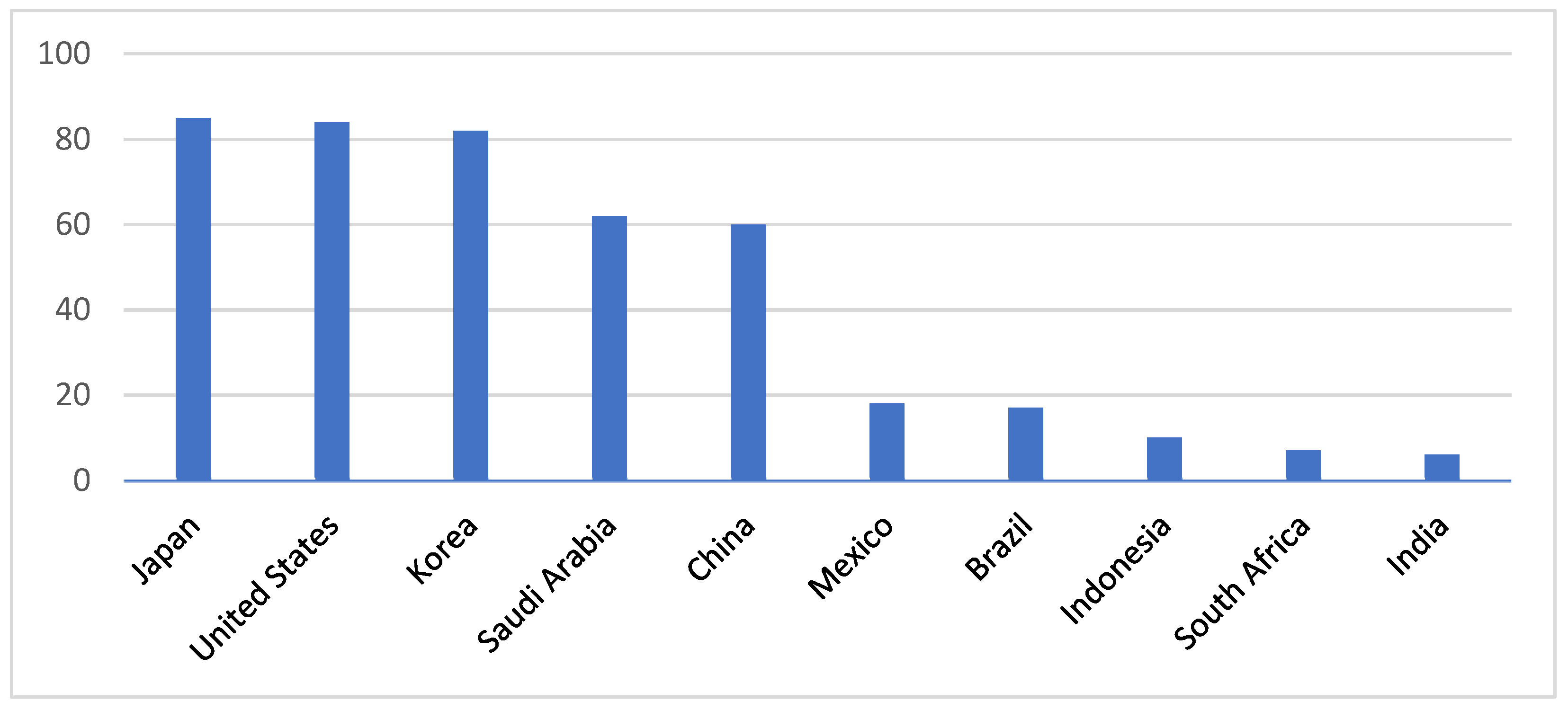
Figure 4.
Diagram of a heat and mass exchanger [22].
Figure 4.
Diagram of a heat and mass exchanger [22].
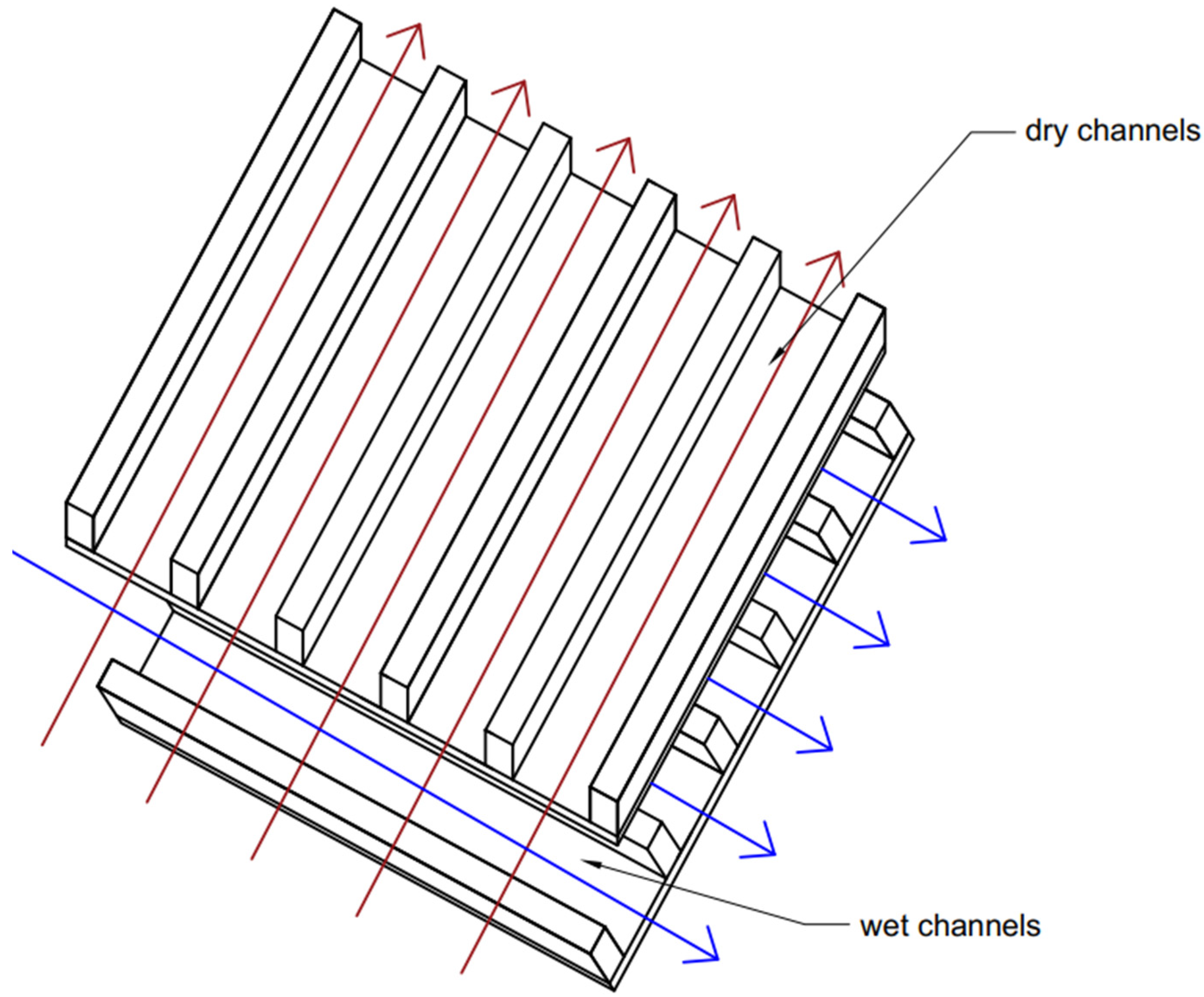
Figure 5.
M-cycle cross-flow evaporative cooler [23].
Figure 5.
M-cycle cross-flow evaporative cooler [23].
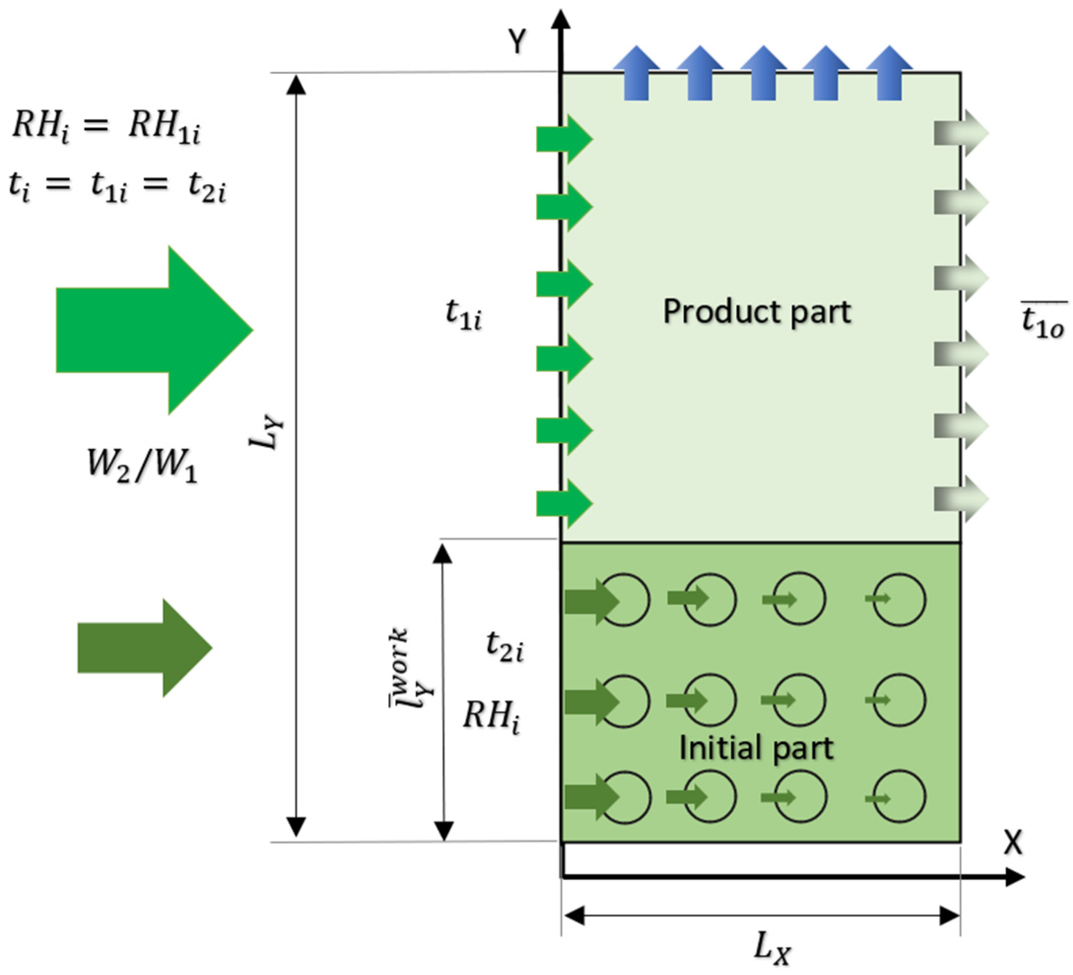
Figure 6.
Distribution of annual documents regarding the M-cycle [34].
Figure 6.
Distribution of annual documents regarding the M-cycle [34].
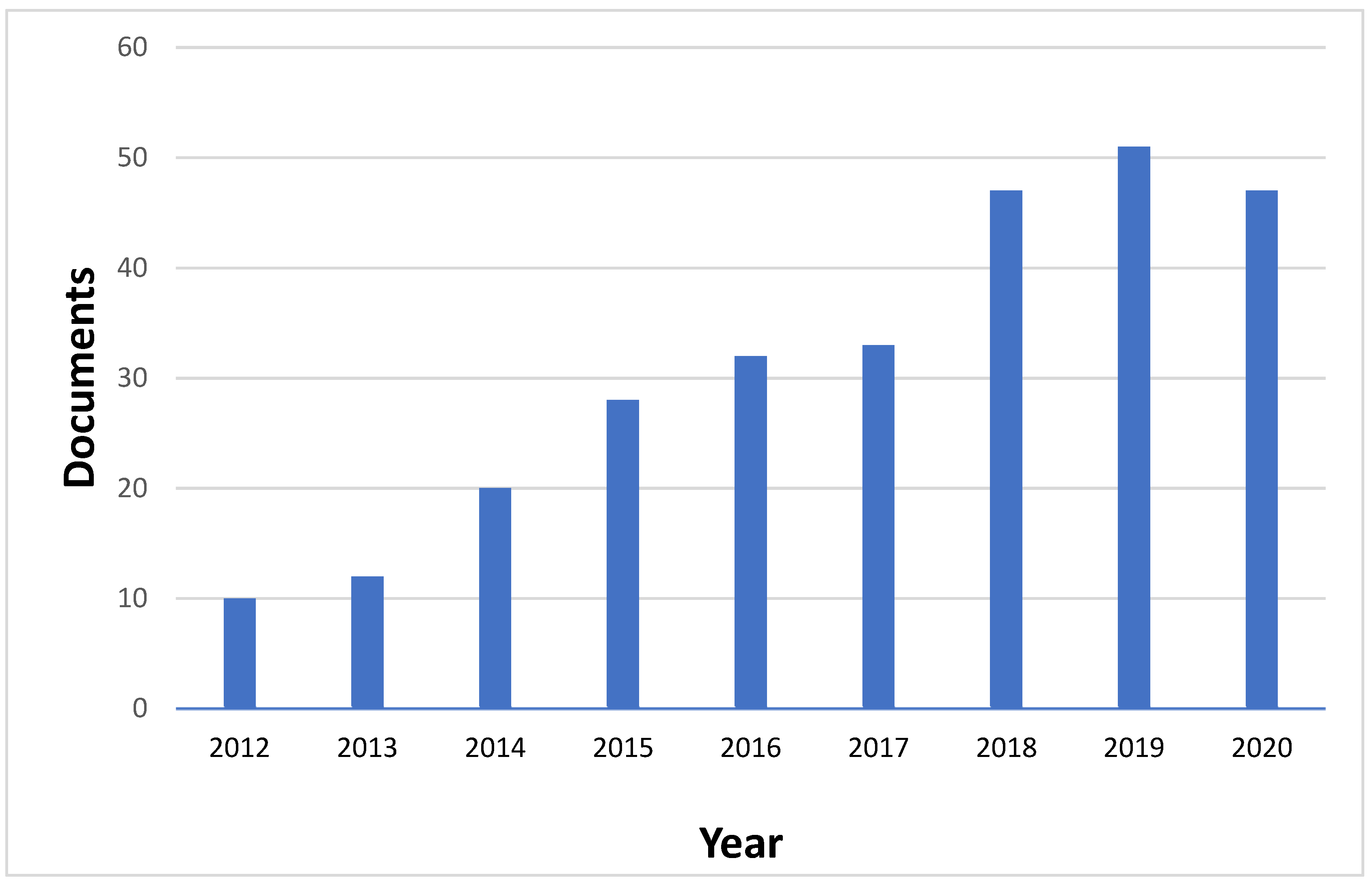
Figure 7.
Visualization of a few indirect evaporative solutions: (a) parallel flow, (b) counter-flow IEC, (c) cross-flow IEC, (d) regenerative IEC [41].
Figure 7.
Visualization of a few indirect evaporative solutions: (a) parallel flow, (b) counter-flow IEC, (c) cross-flow IEC, (d) regenerative IEC [41].

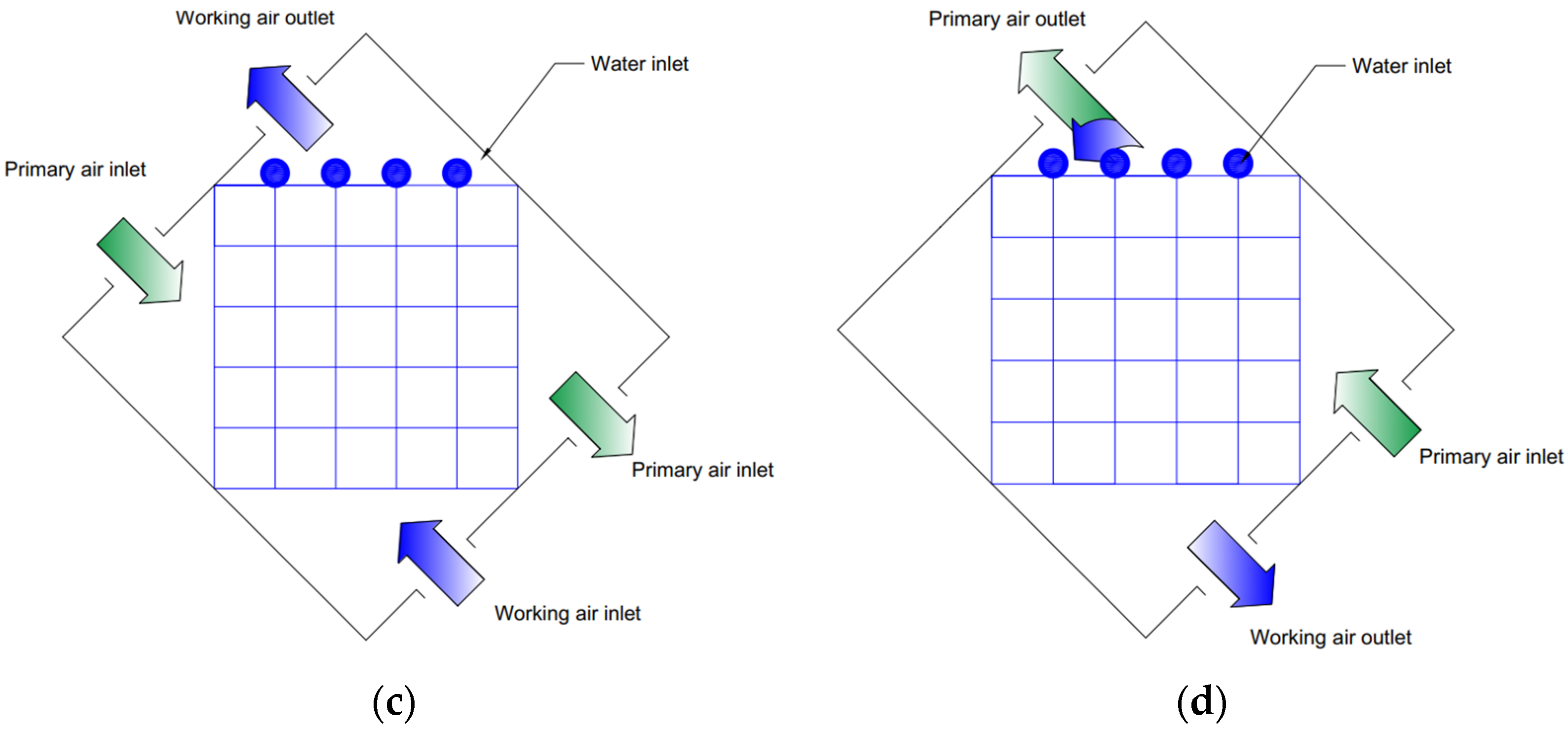
Figure 8.
Diagram of a typical solar DAC system [55].
Figure 8.
Diagram of a typical solar DAC system [55].
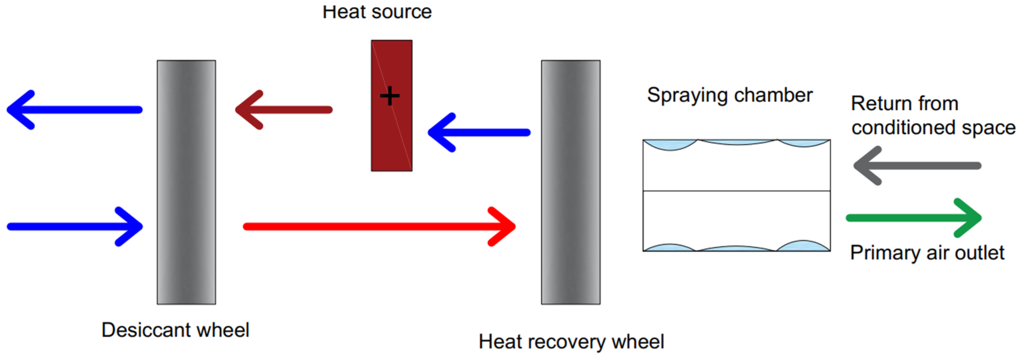
Figure 9.
Different configurations of DAC with (a) regenerative M-cycle, (b) cross-flow M-cycle HMX, and (c) cross-flow M-cycle [58].
Figure 9.
Different configurations of DAC with (a) regenerative M-cycle, (b) cross-flow M-cycle HMX, and (c) cross-flow M-cycle [58].
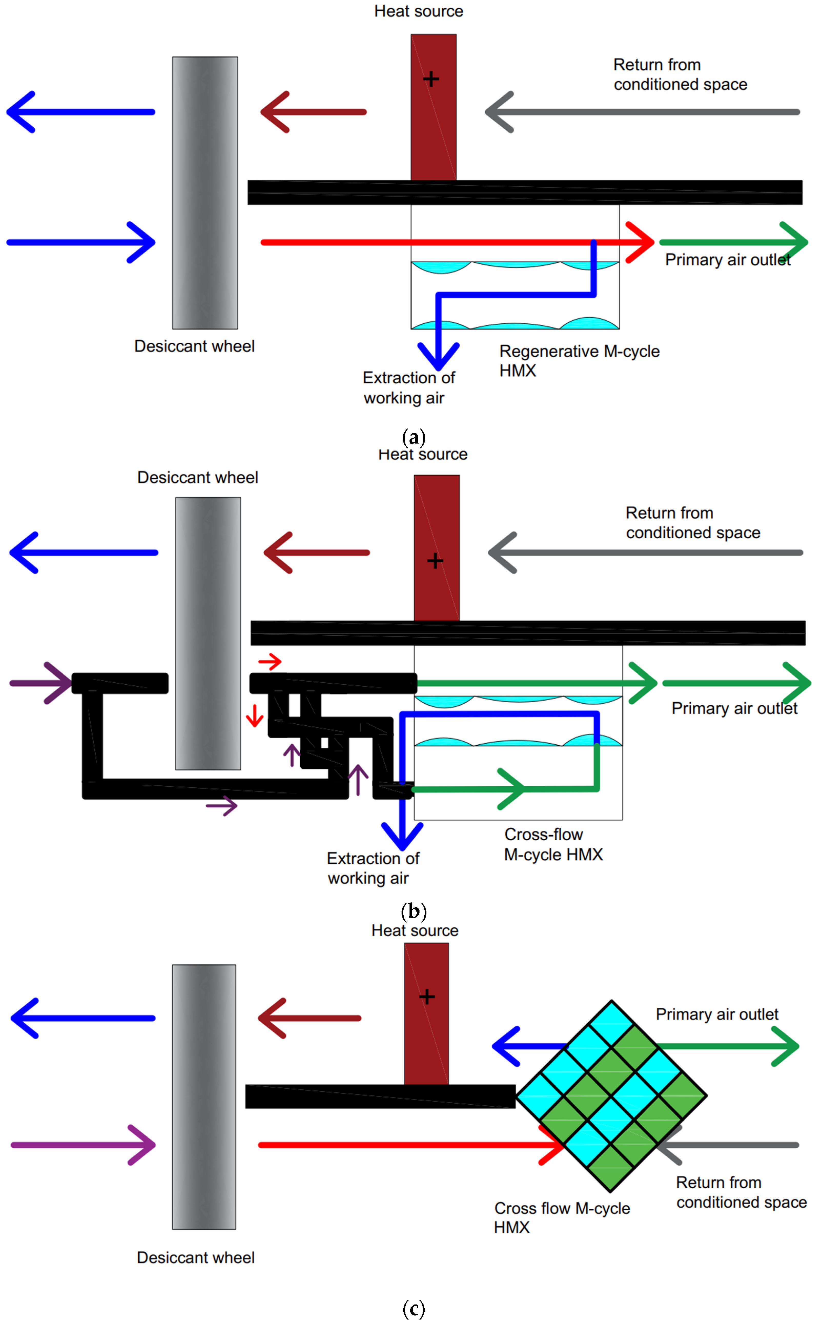
Figure 10.
H-MAC diagram [52].
Figure 10.
H-MAC diagram [52].
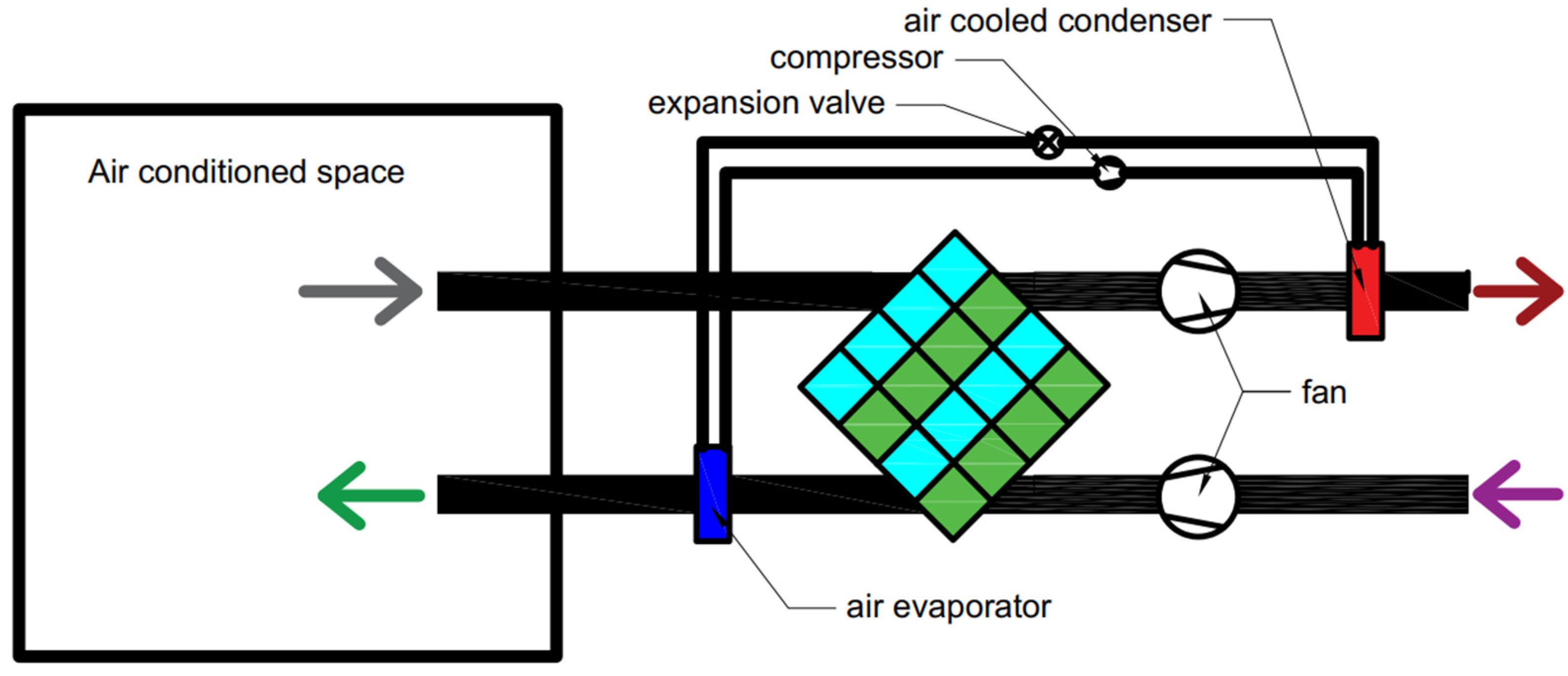
Figure 11.
M-cooling tower: (a) diagram; (b) temperature distribution in the MCT [62].
Figure 11.
M-cooling tower: (a) diagram; (b) temperature distribution in the MCT [62].

Figure 12.
Large-scale cooling tower with the M-cycle [63].
Figure 12.
Large-scale cooling tower with the M-cycle [63].

Figure 13.
M-condenser: (a) EER visualization based on ambient air temperature; (b) schematic arrangement [11].
Figure 13.
M-condenser: (a) EER visualization based on ambient air temperature; (b) schematic arrangement [11].

Publisher’s Note: MDPI stays neutral with regard to jurisdictional claims in published maps and institutional affiliations. |
© 2022 by the authors. Licensee MDPI, Basel, Switzerland. This article is an open access article distributed under the terms and conditions of the Creative Commons Attribution (CC BY) license (https://creativecommons.org/licenses/by/4.0/).
Share and Cite
MDPI and ACS Style
Taler, J.; Jagieła, B.; Jaremkiewicz, M. Overview of the M-Cycle Technology for Air Conditioning and Cooling Applications. Energies 2022, 15, 1814. https://doi.org/10.3390/en15051814
AMA Style
Taler J, Jagieła B, Jaremkiewicz M. Overview of the M-Cycle Technology for Air Conditioning and Cooling Applications. Energies. 2022; 15(5):1814. https://doi.org/10.3390/en15051814
Chicago/Turabian StyleTaler, Jan, Bartosz Jagieła, and Magdalena Jaremkiewicz. 2022. "Overview of the M-Cycle Technology for Air Conditioning and Cooling Applications" Energies 15, no. 5: 1814. https://doi.org/10.3390/en15051814
Note that from the first issue of 2016, this journal uses article numbers instead of page numbers. See further details here.