
Bidirectional Power Control for a Three-Phase Grid-Connected Inverter under Unbalanced Grid Conditions Using a Proportional-Resonant and a Modified Time-Domain Symmetrical Components Extraction Method †

Abstract
:1. Introduction
- Bi-directional control of the real and reactive power under unbalanced grid situations for a three-phase inverter;
- The ripple in real and reactive power was significantly reduced;
- Balance the PCC voltages and grid currents;
- Because the unbalanced problem was solved, the unbalanced load will not have an impact on any other loads linked to the grid;
- There is no requirement for a PLL because a conventional PR controller was used;
- The symmetrical components extraction method was performed. Compared to prior symmetrical component approaches that used complicated transformations, this approach needs less computations;
- The three techniques for controlling power and balancing the grid—MPRS, SCEM-P, and SCEM-PR—described in the literature were only effective when the grid was strong and the grid impedance was ignored. Moreover, the power control was in one direction only. Here, the SCEM-PR (which is a method that takes the advantages of both SCEM-P and MPRS) was modified to control the power and balance the grid under weak grid conditions when the unbalanced grid impedance is considered.
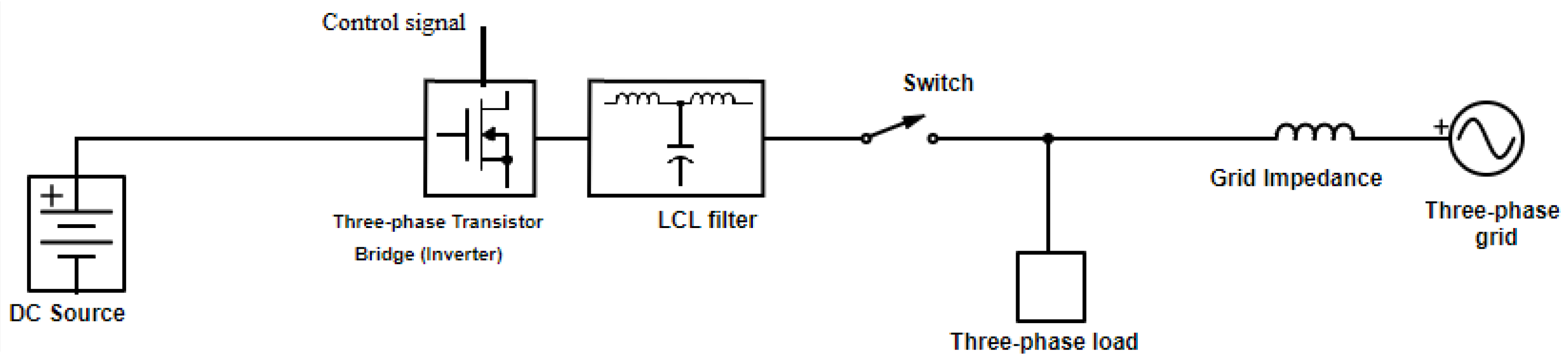
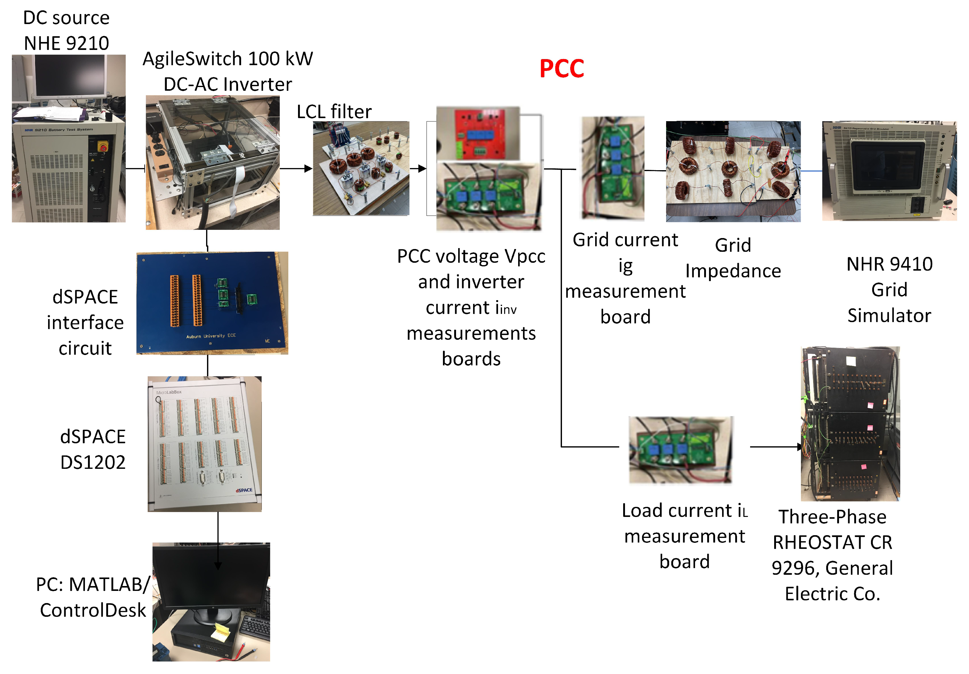
2. System Description
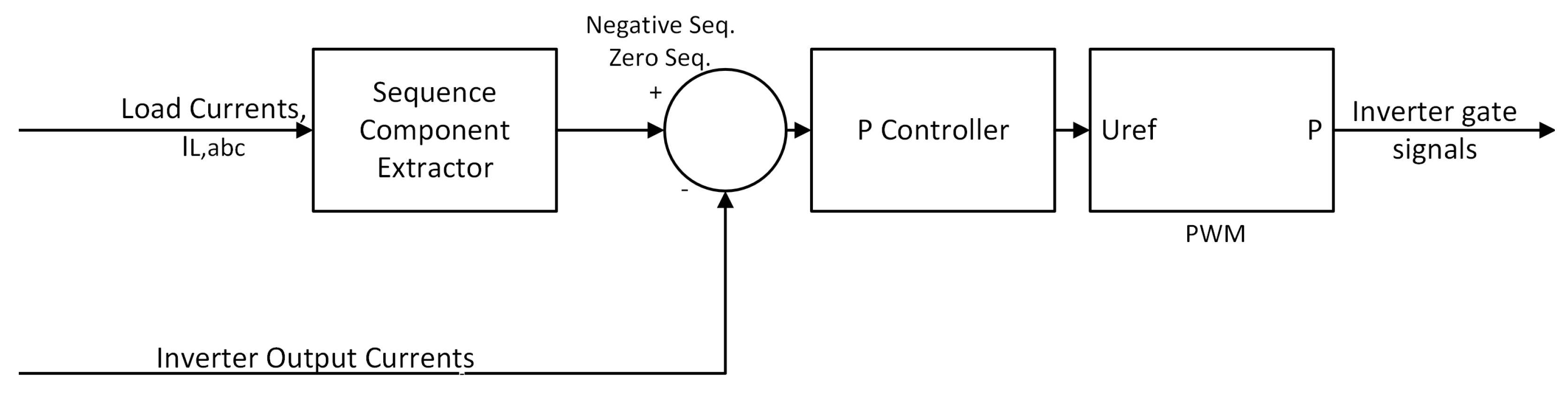
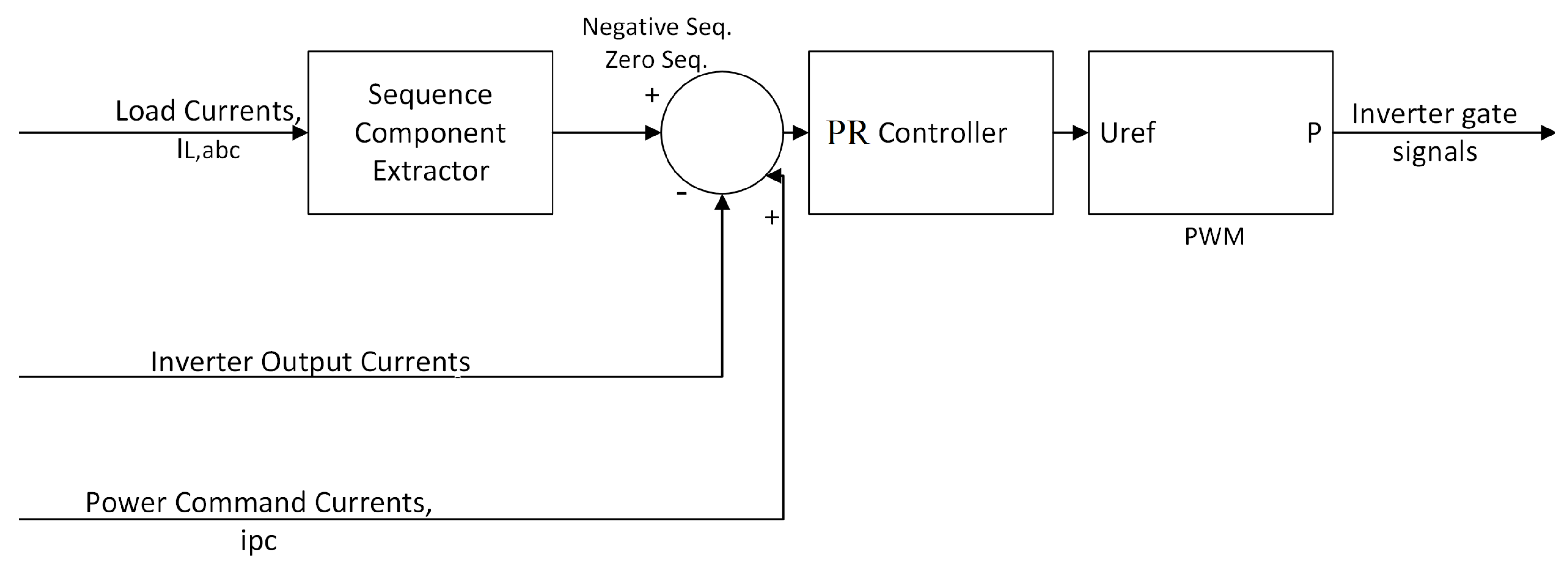
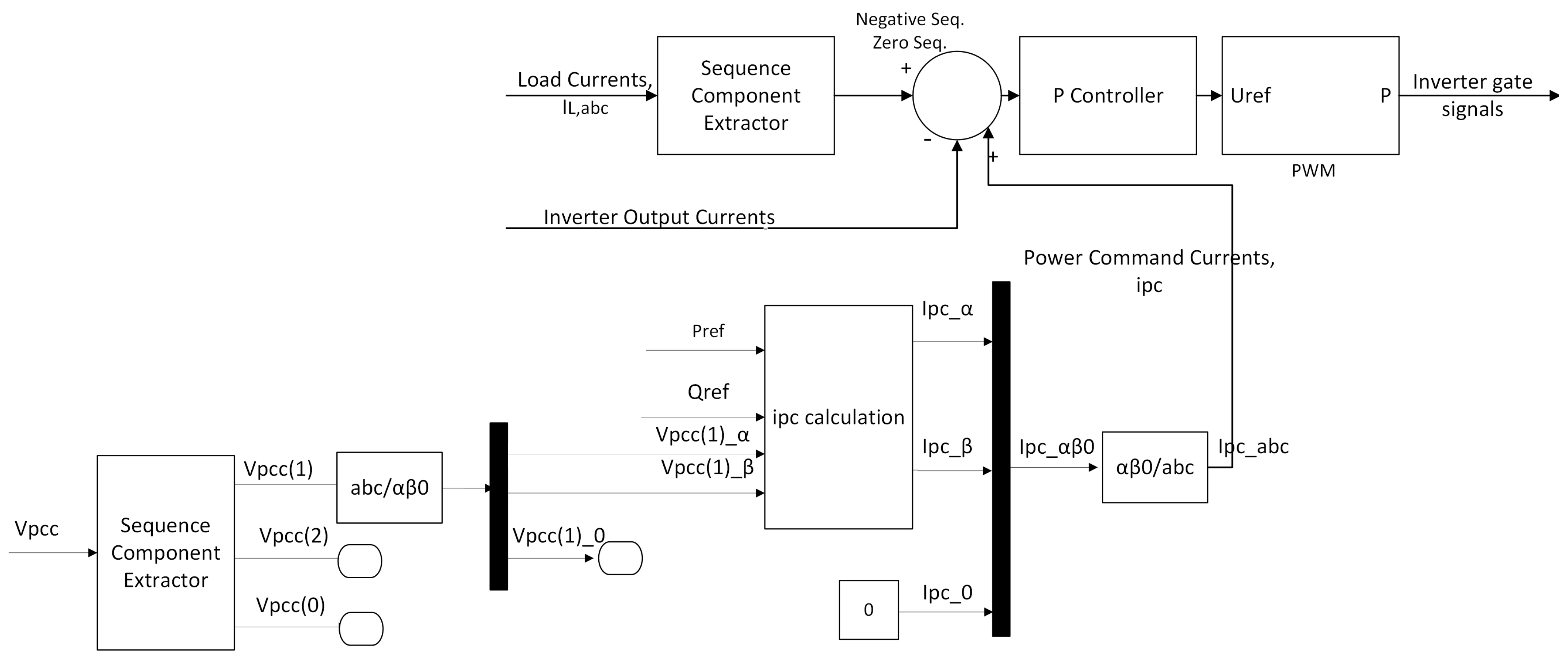
3. Current Control
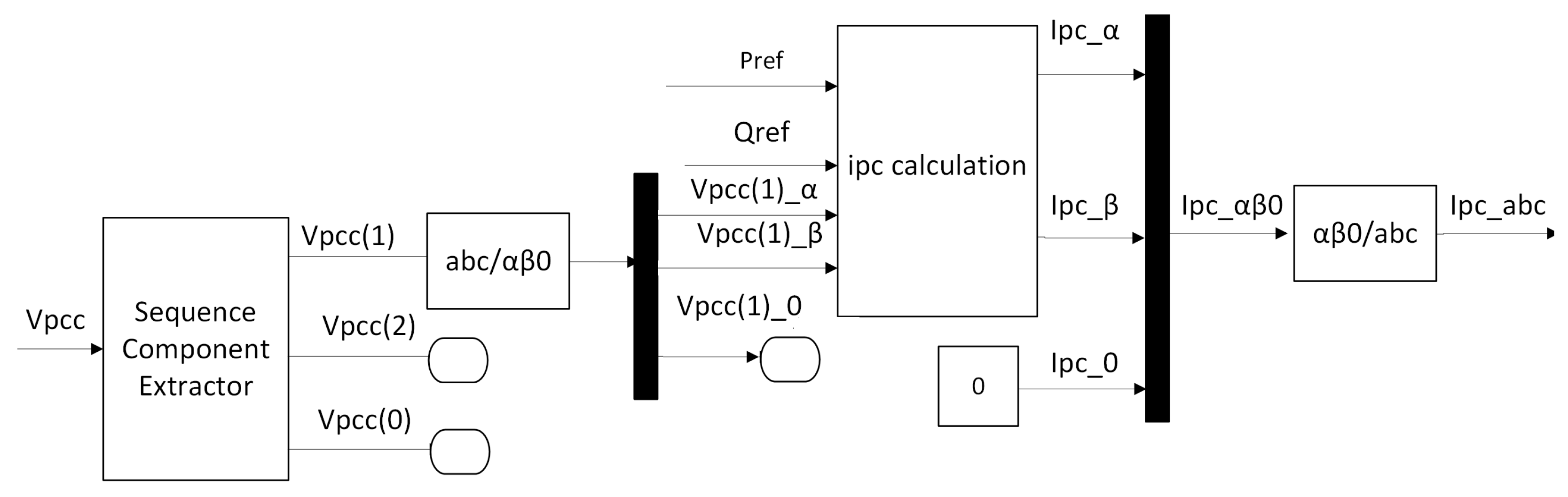
4. Bidirectional Power Control
5. Case Studies
5.1. Simulation Results
5.1.1. Balanced Grid Impedance
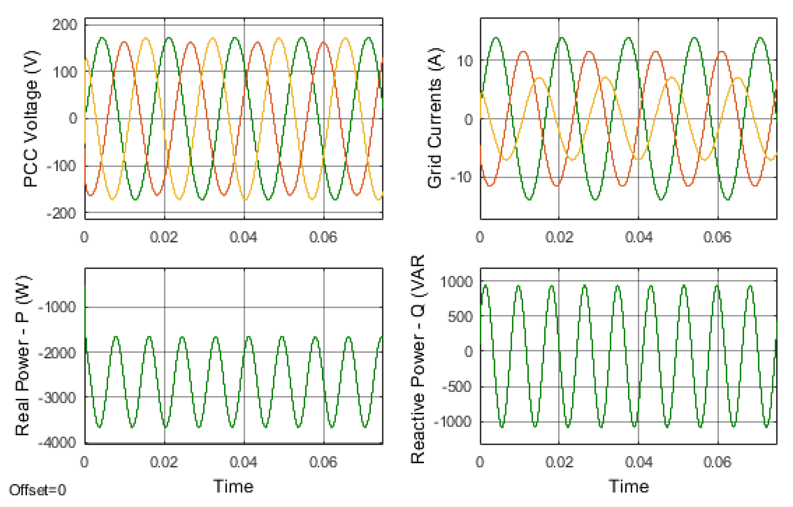
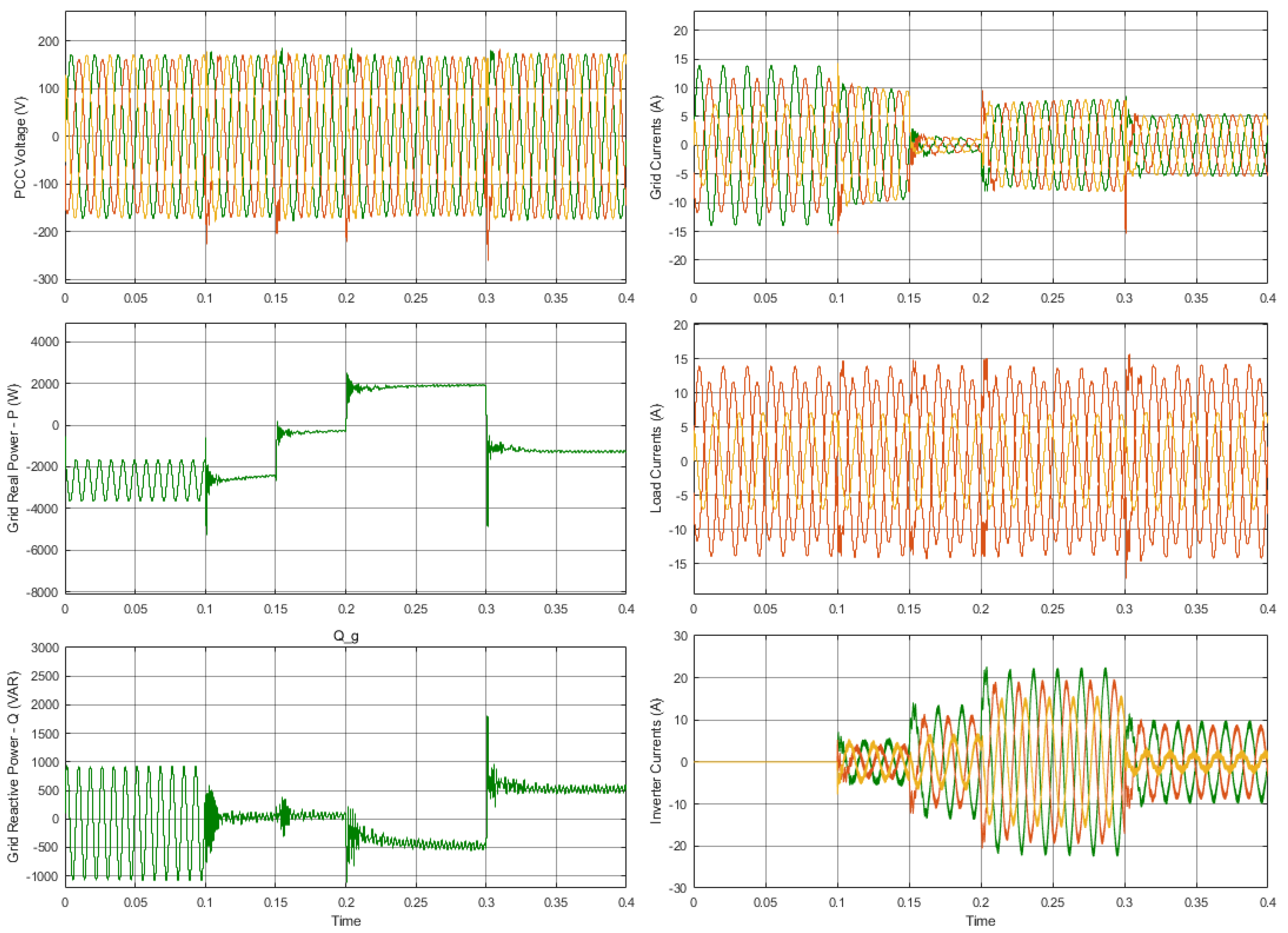
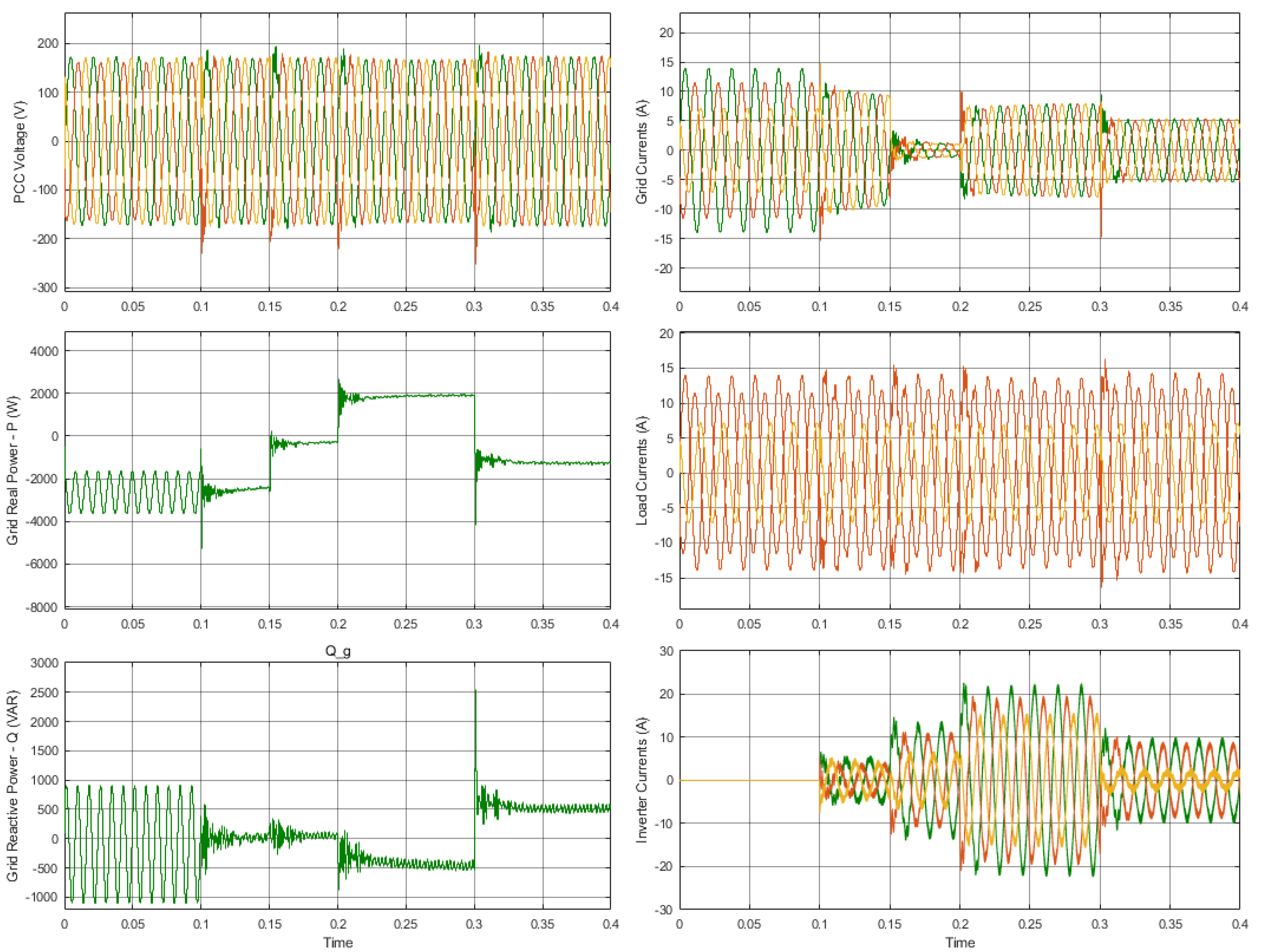
- For s, the grid is connected only to to the unbalanced load resulting in unbalanced and . In addition, there is high ripple in the real and reactive power waveforms which will affect other loads linked to the PCC.
- For s, the inverter was turned on and controlled as a shunt active power filter by basically assuming the power command current reference value to be zero . Thus, the mode of operation is to balance the grid without controlling the power. Within a few milliseconds, the inverter can balance the grid currents, PCC voltages, and minimize the ripple in the real and reactive power.
- For s, the control command has the capability to balance the system and achieve a zero desired real and reactive power to the grid (0 kW, 0 var). The proposed method can achieve this target with a small error.
- For s, (2 kW, −500 var) while balancing the grid. The proposed method can supply the grid with the desired power as well as balance and .
- At s, the and were changed to be −1 kW and 500 var. As a result, the proposed technique can control power in both directions under unbalanced grid situations.
5.1.2. Unbalanced Grid Impedance
5.2. Experimental Results
5.2.1. Balanced Grid Impedance
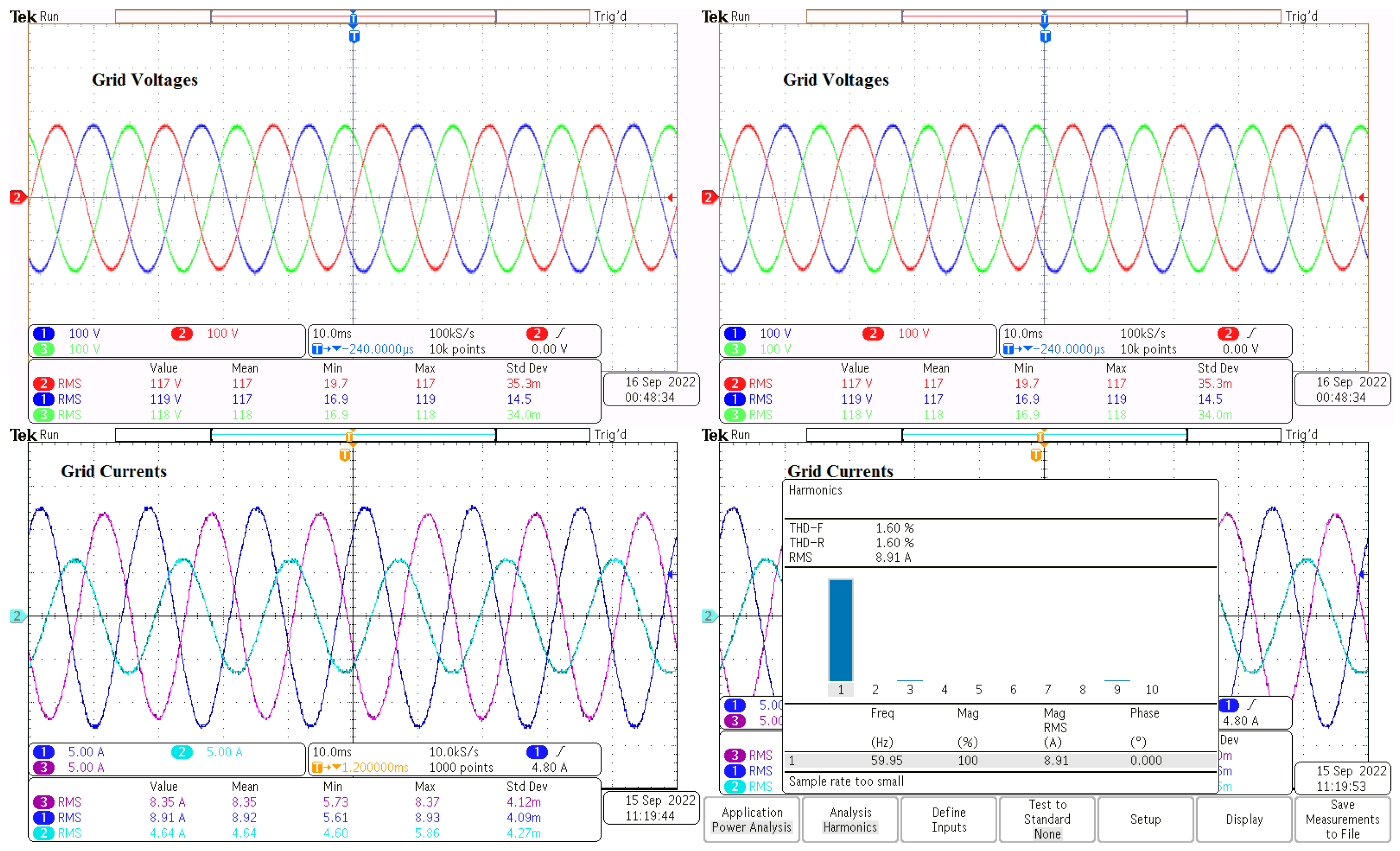
- The unbalanced three-phase load is linked to the PCC point and the grid without energizing the inverter. At this point, the unbalanced load will create unbalanced grid currents and PCC voltages as shown in Figure 15. A Tektronix MDO3024 oscilloscope was used to obtain these results.
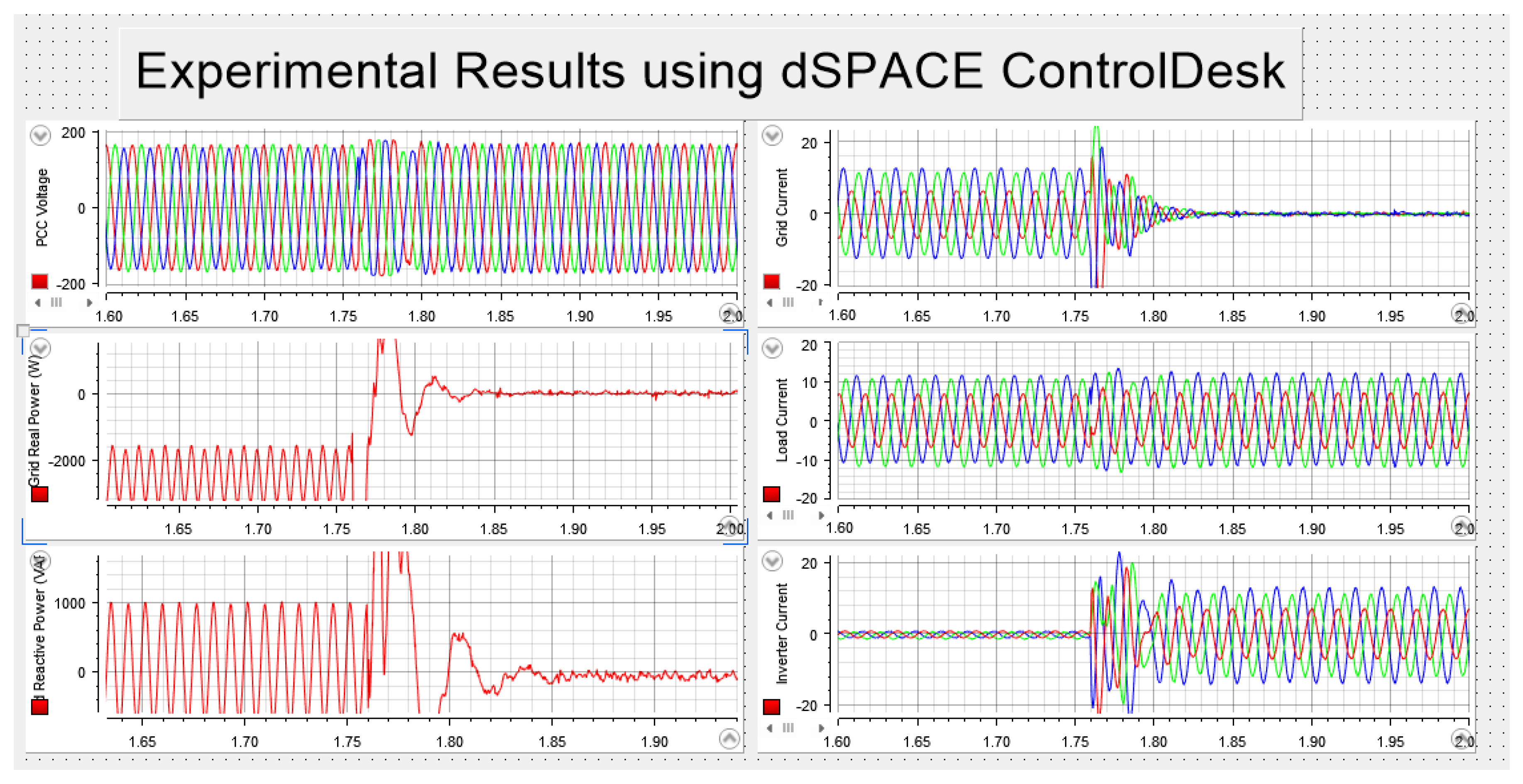
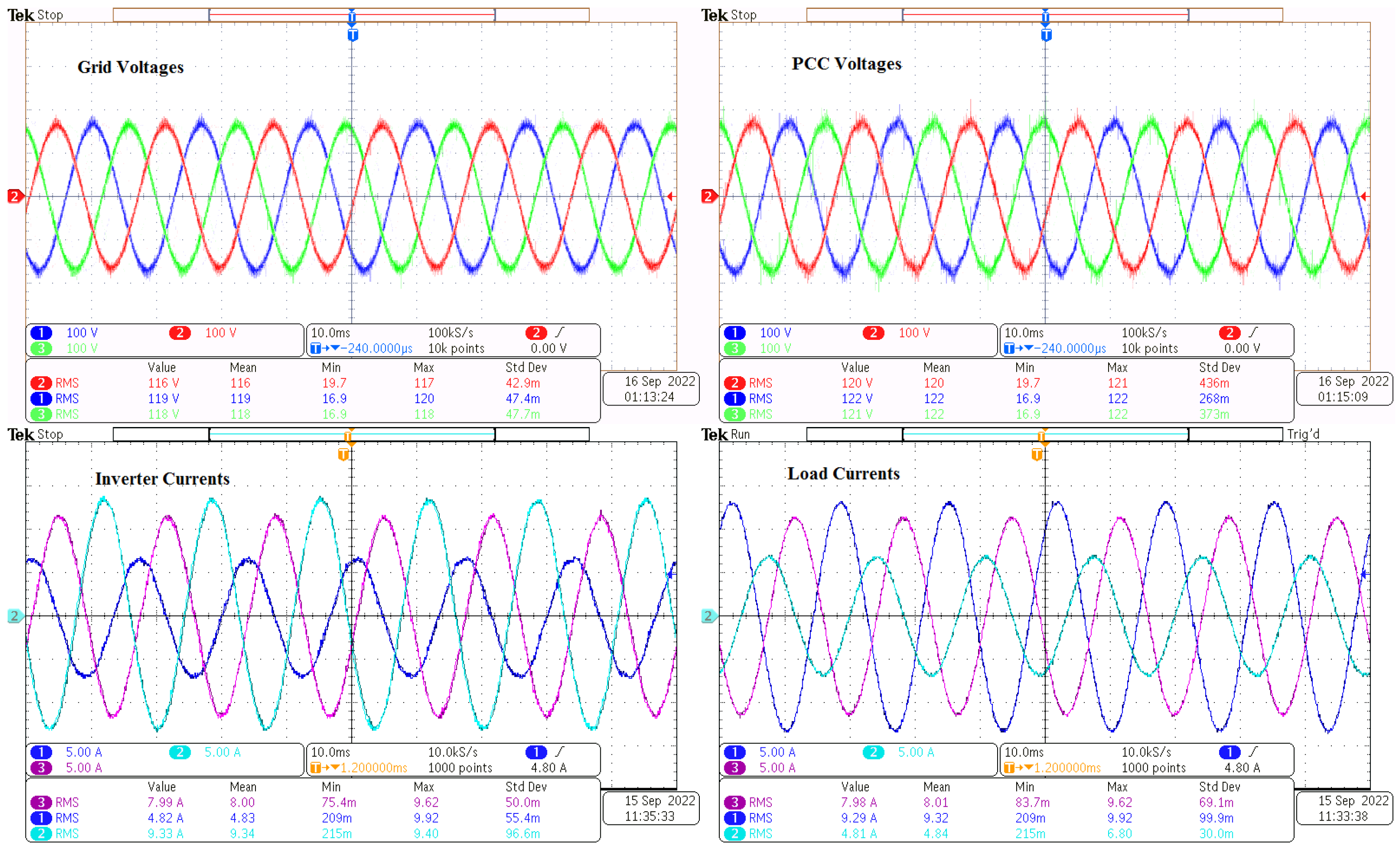
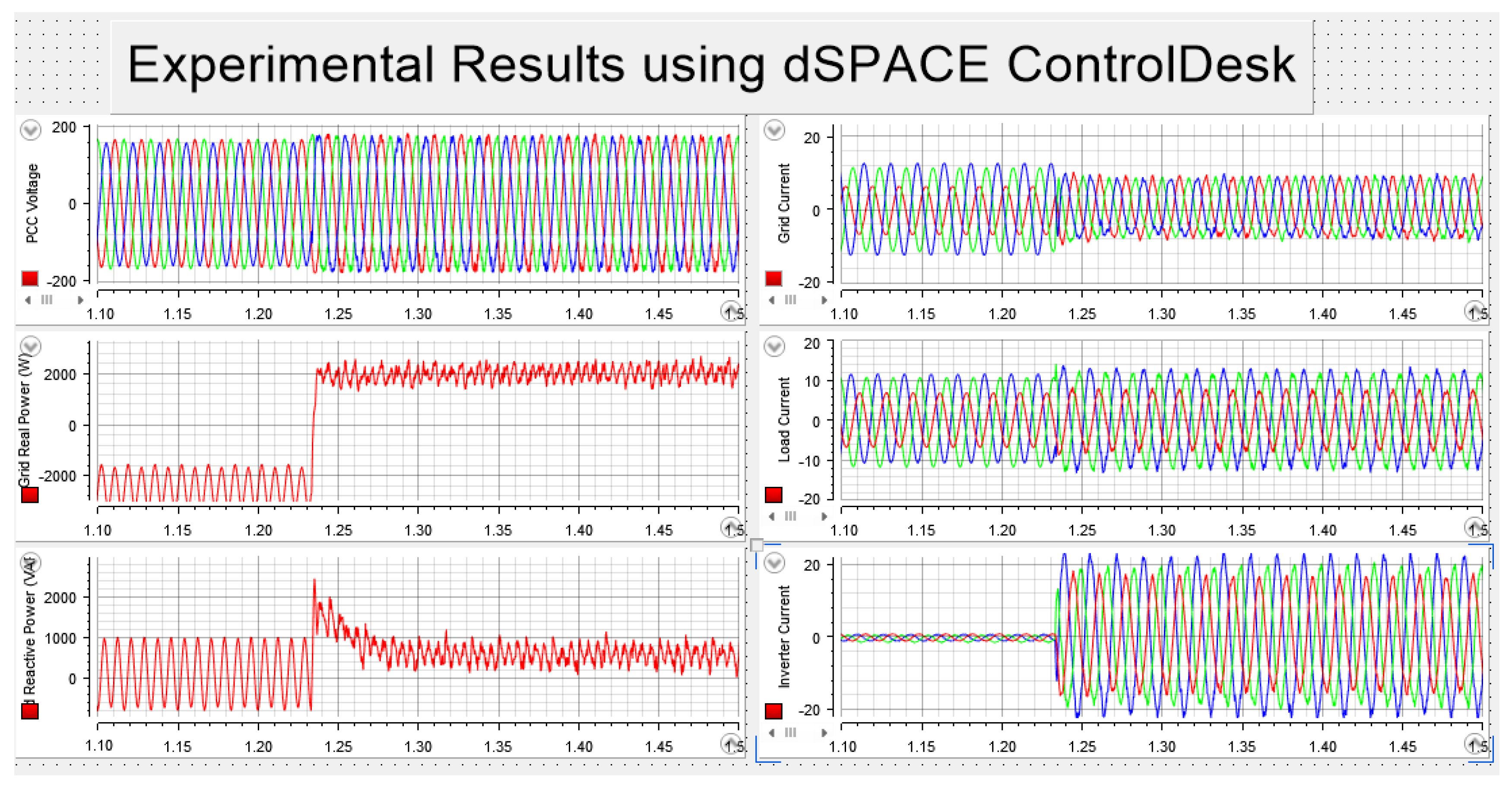
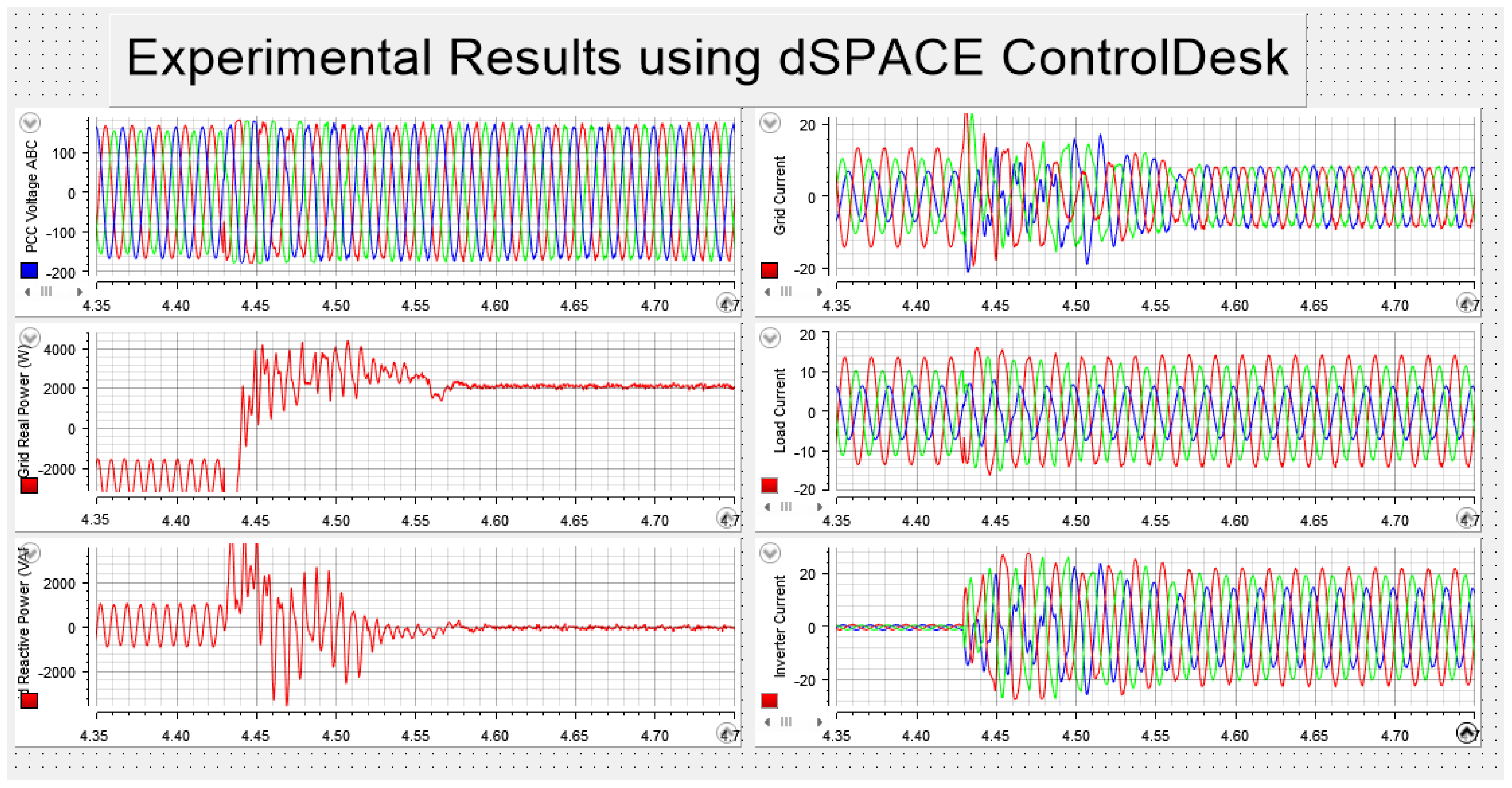
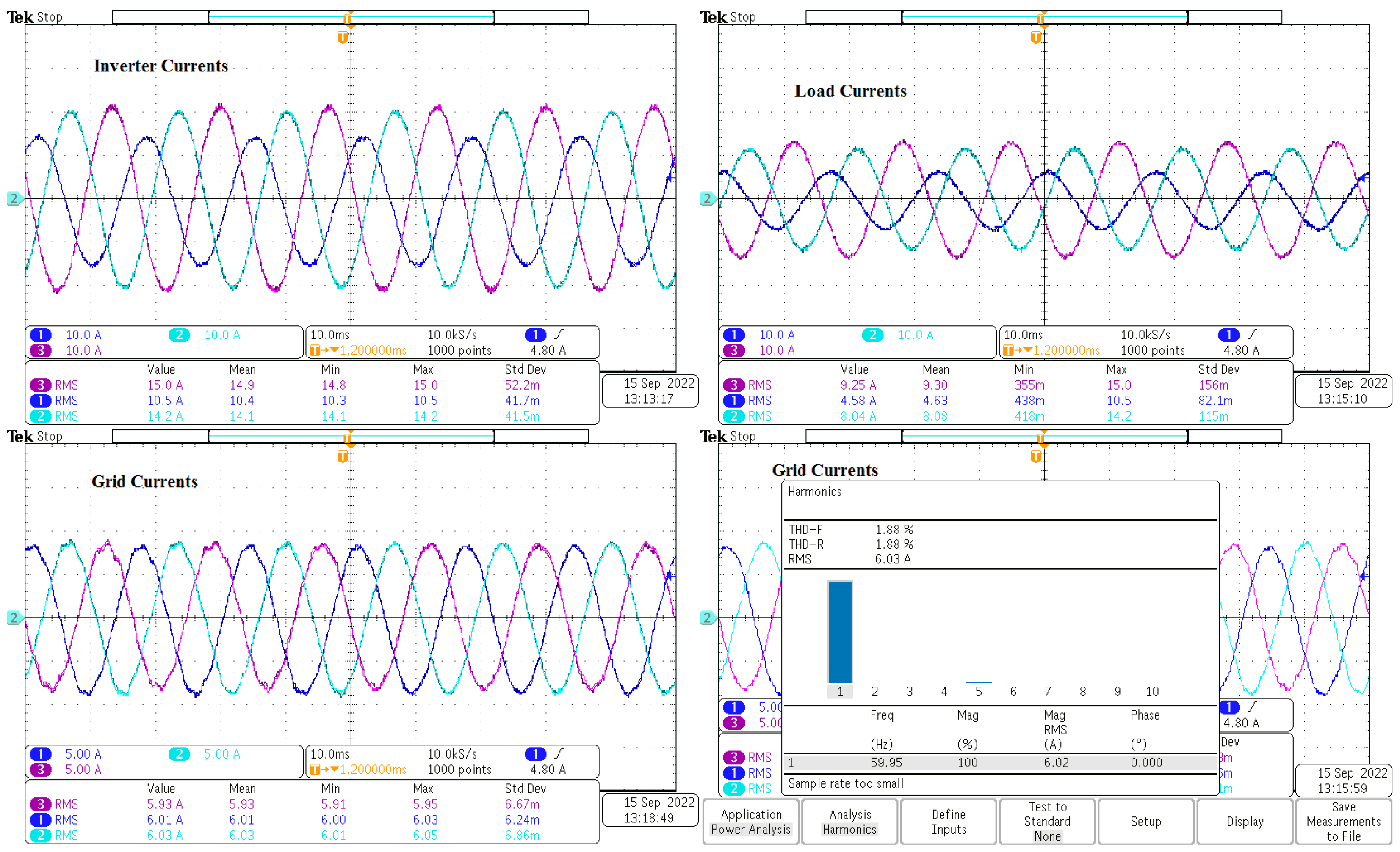
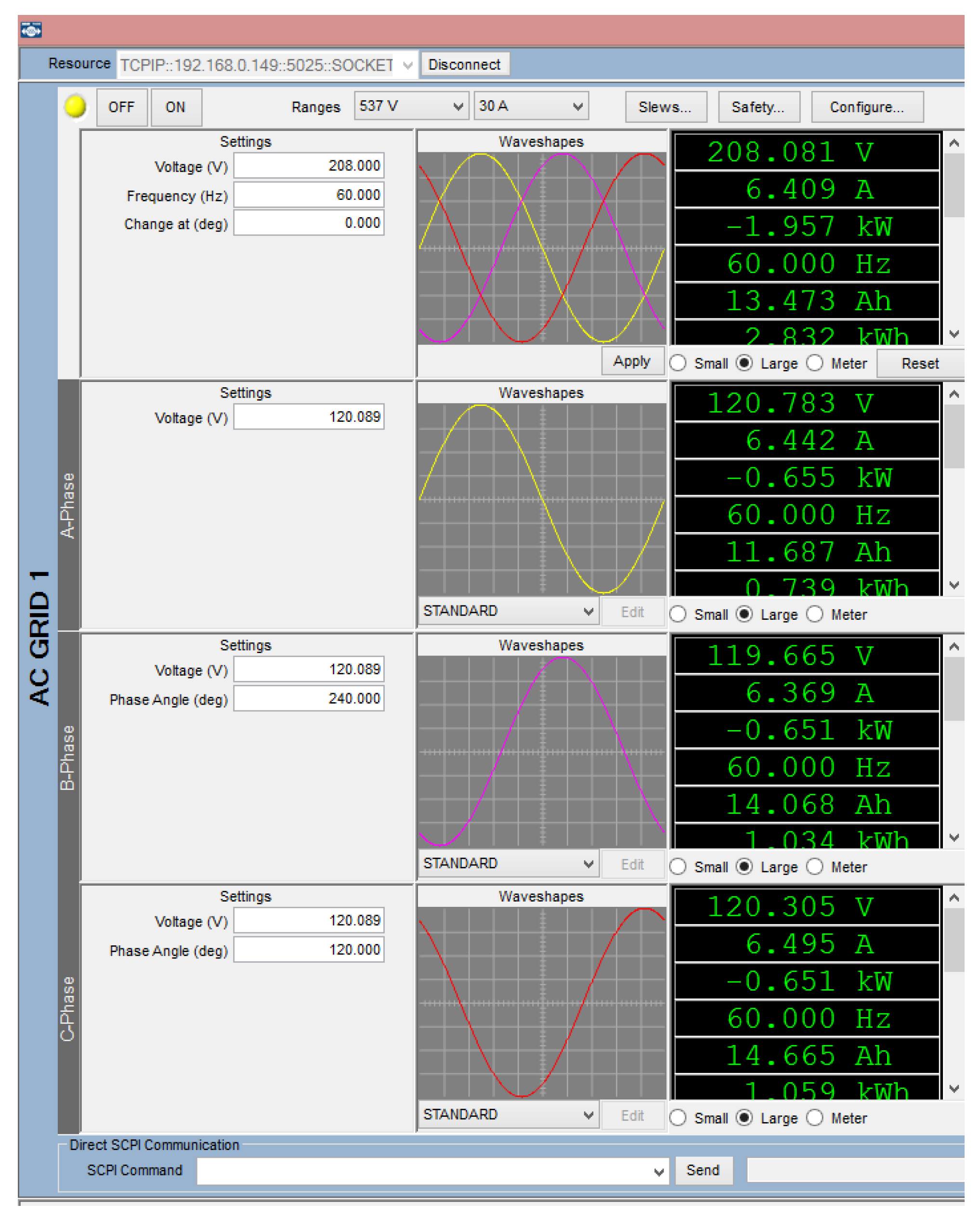
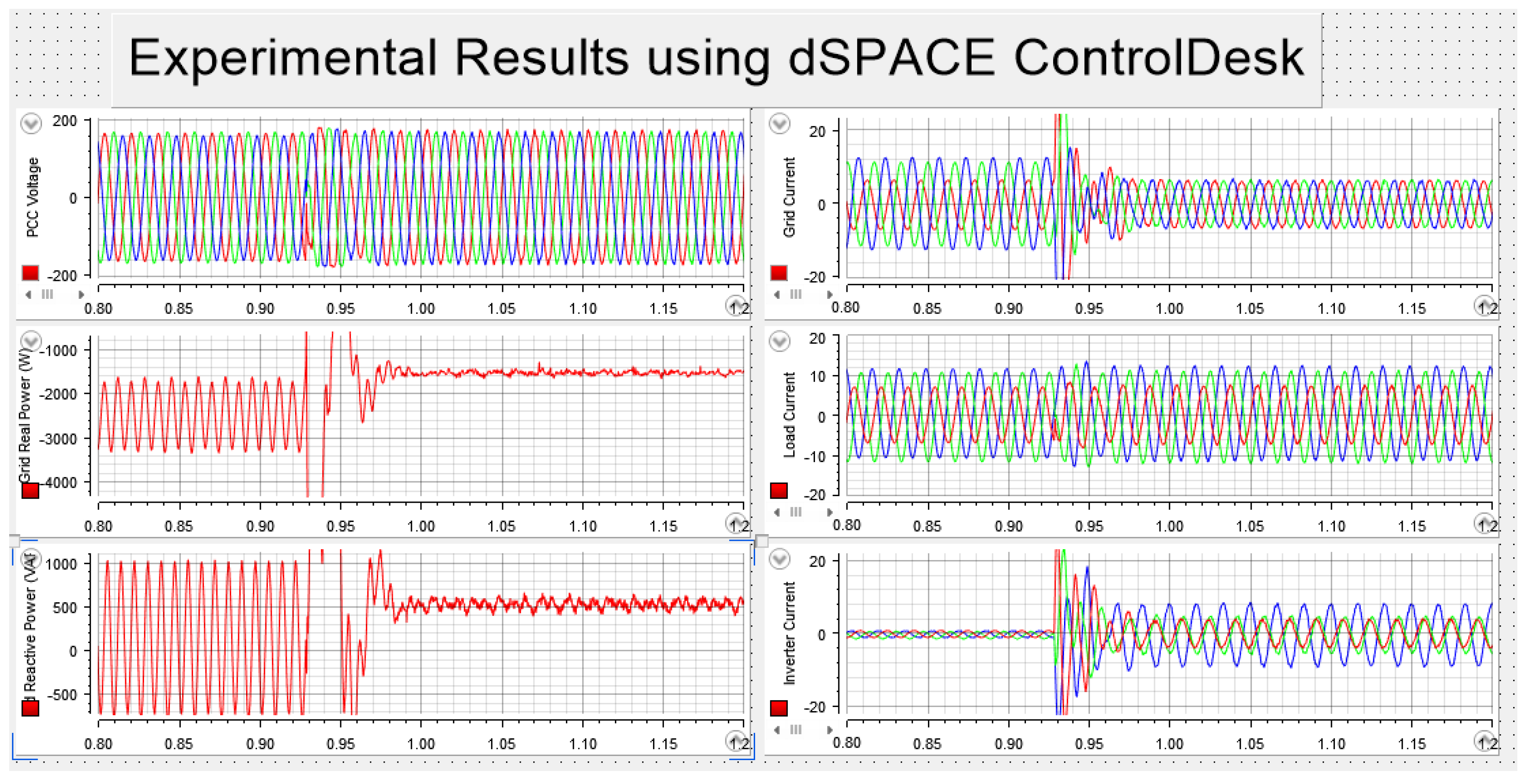
- The inverter was turned on with the proposed method, and the reference P and Q are 0 kW and 0 var. The proposed method took less than 10 ms to balance the and as shown in the dSPACE ControlDesk toolbox results in Figure 16. The proposed method can track the reference real and reactive power as well. Figure 17 illustrates the experimental findings for the grid voltages (), PCC voltages (), inverter currents (), and load currents () collected by a Tektronix MDO3024 oscilloscope. The experimental results utilizing the grid simulator NHR 9400 panel are shown in Figure 18.
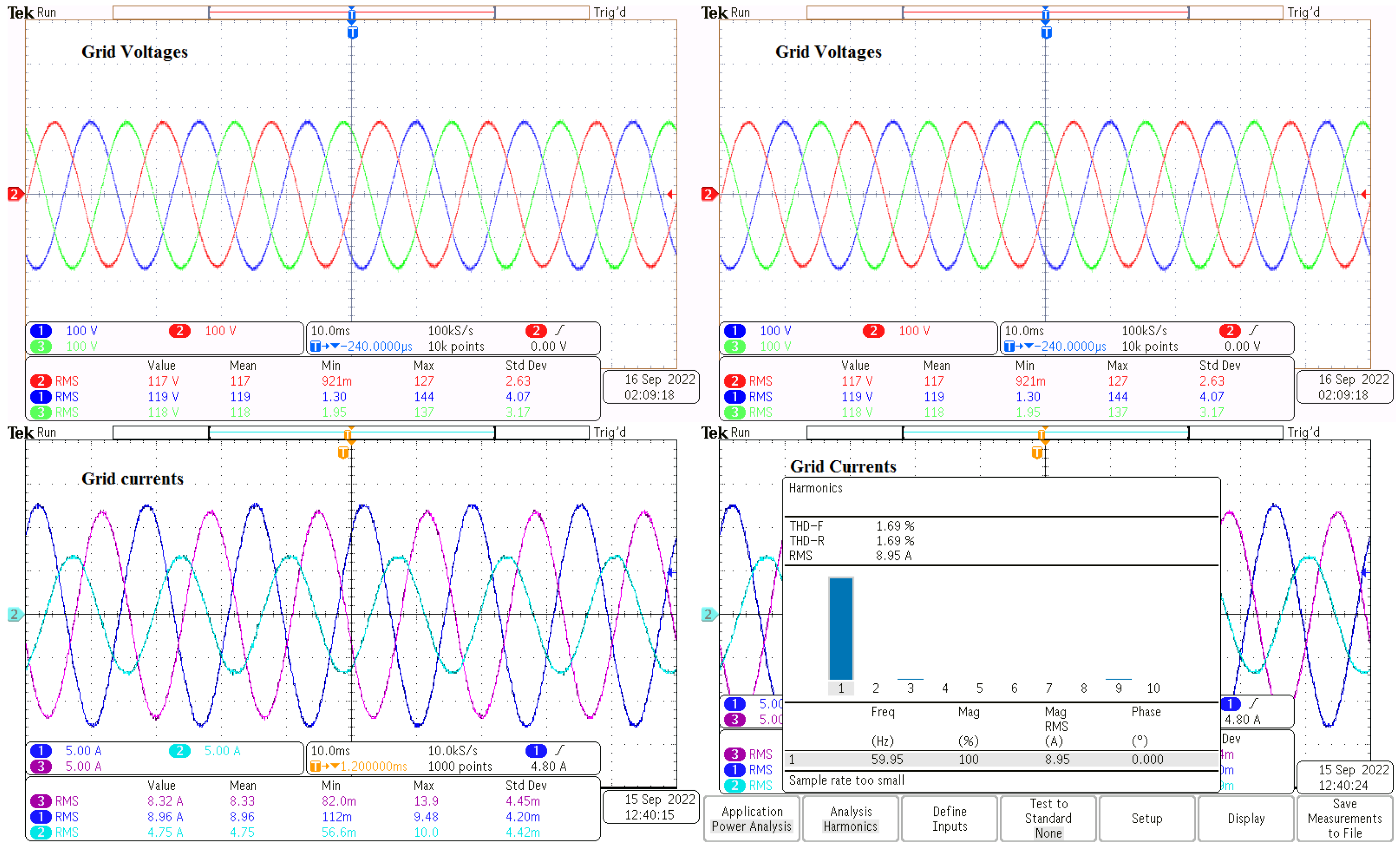
- Assuming and , the system can track the desired reference P and Q as well as balance the and at the same time. Figure 19 displays the dSPACE Controldesk findings, and Figure 20 shows the oscilloscope results for , , and . Grid currents have a total harmonic distortion percentage (THD%) of 2.62 %, which is regarded as an acceptable number. Although the THD% for the grid currents was 1.6% prior to energizing the inverter, the suggested method’s purpose is to accomplish a bidirectional power control and eliminate the unbalance of the grid currents and PCC voltages, improving the THD% is not a part of this work. Figure 21 displays the experimental results utilizing the grid simulator NHR 9400 panel. Note that the direction is from the inverter to the grid, while the NHR 9400 measures the power from the grid to the inverter. Therefore, .
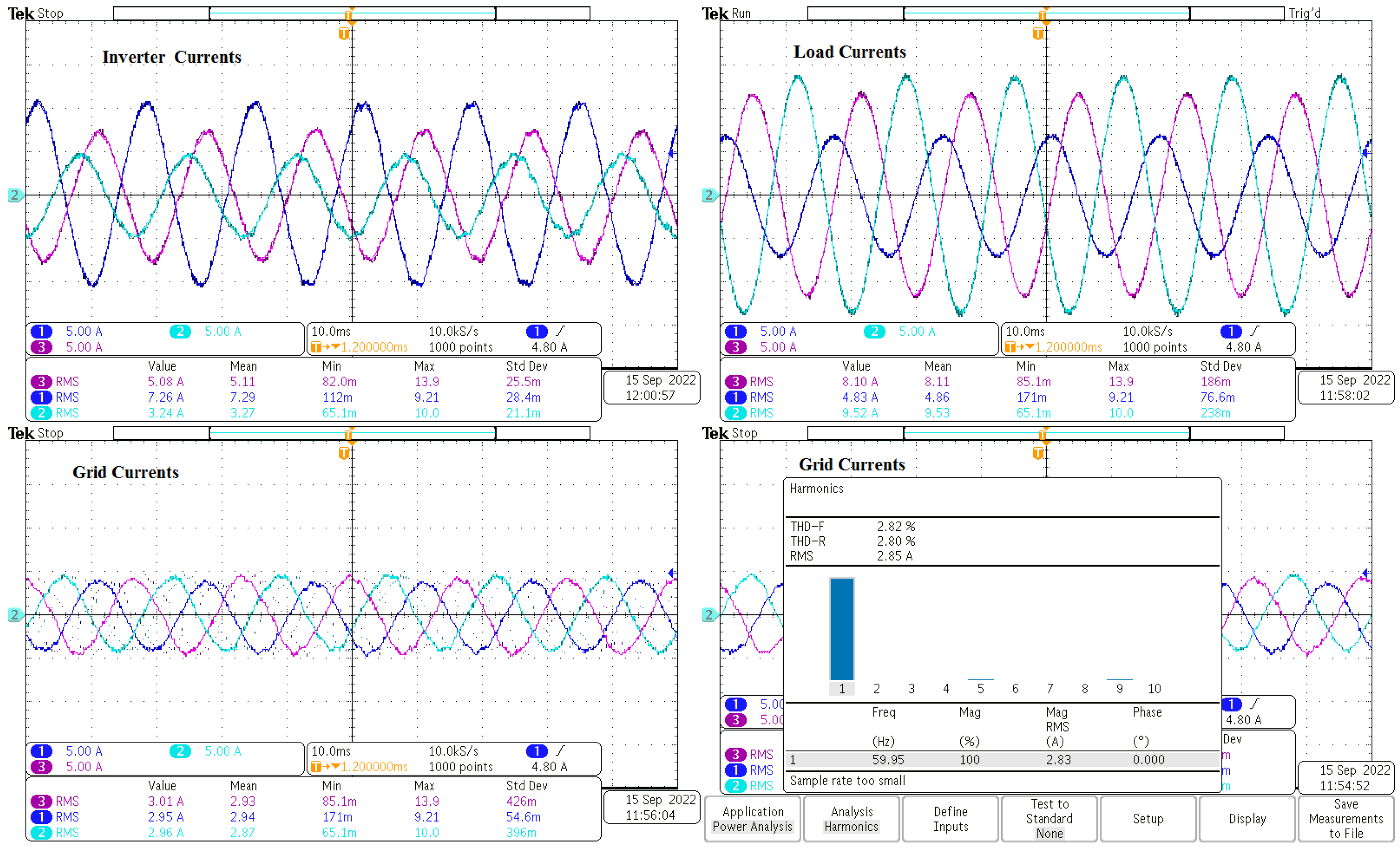
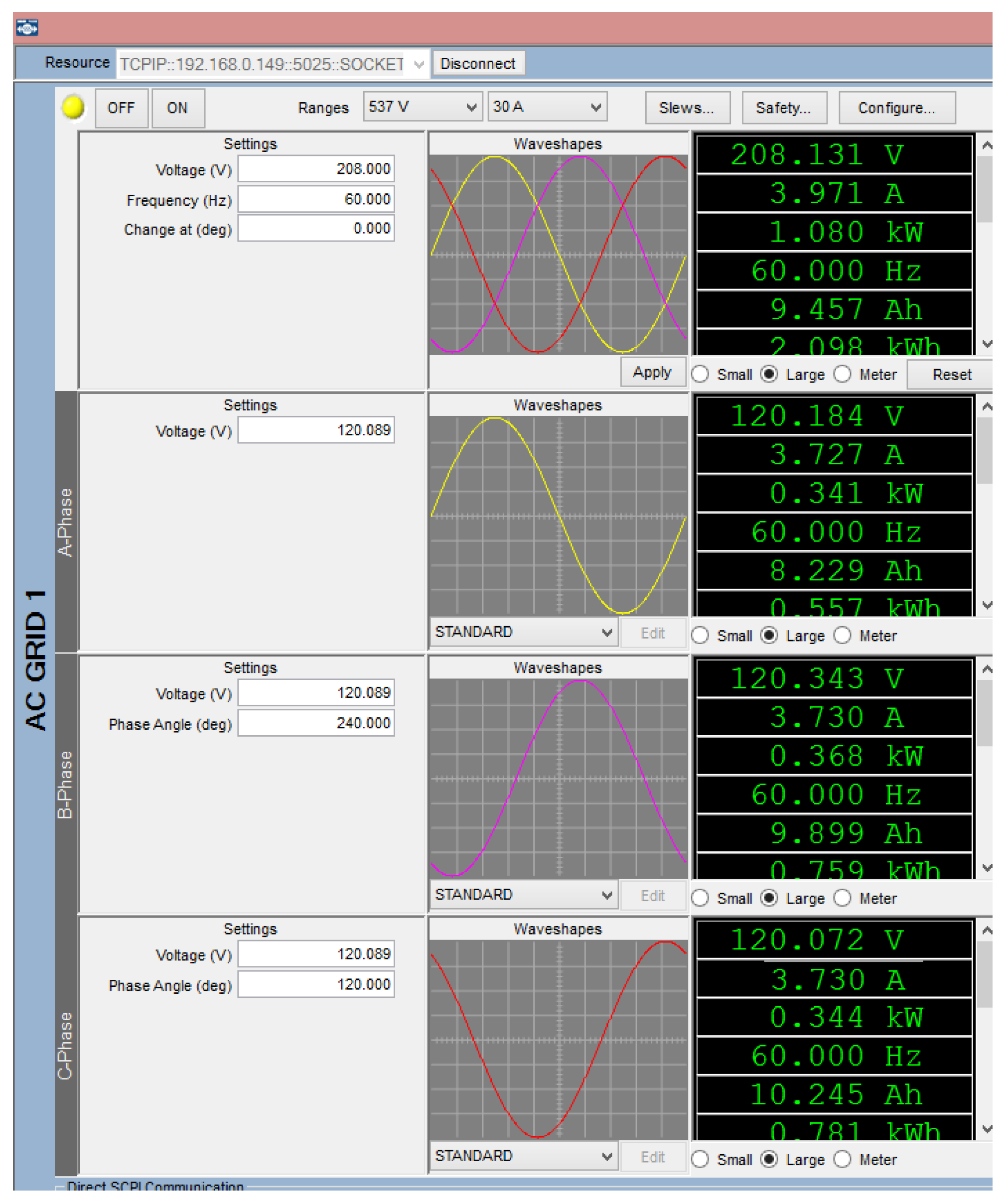
- At and , the suggested method can work in the four-quadrant power control mode in addition to balancing the three-phase grid currents and PCC voltages under an unbalanced three-phase load and balanced grid impedances. The experimental results using dSPACE Controldesk, oscilloscope, and grid simulator NHR 9400 are shown in Figure 22, Figure 23 and Figure 24, respectively. The THD% value of the grid currents is 2.82%. The desired power has the opposite sign of the NHR 9400 readings ().
5.2.2. Unbalanced Grid Impedance
- The unbalanced three-phase load is linked to the PCC point and the grid without energizing the inverter. At this point, the unbalanced load will create unbalanced grid currents and PCC voltages as shown in Figure 25. A Tektronix MDO3024 oscilloscope was used to obtain these results.
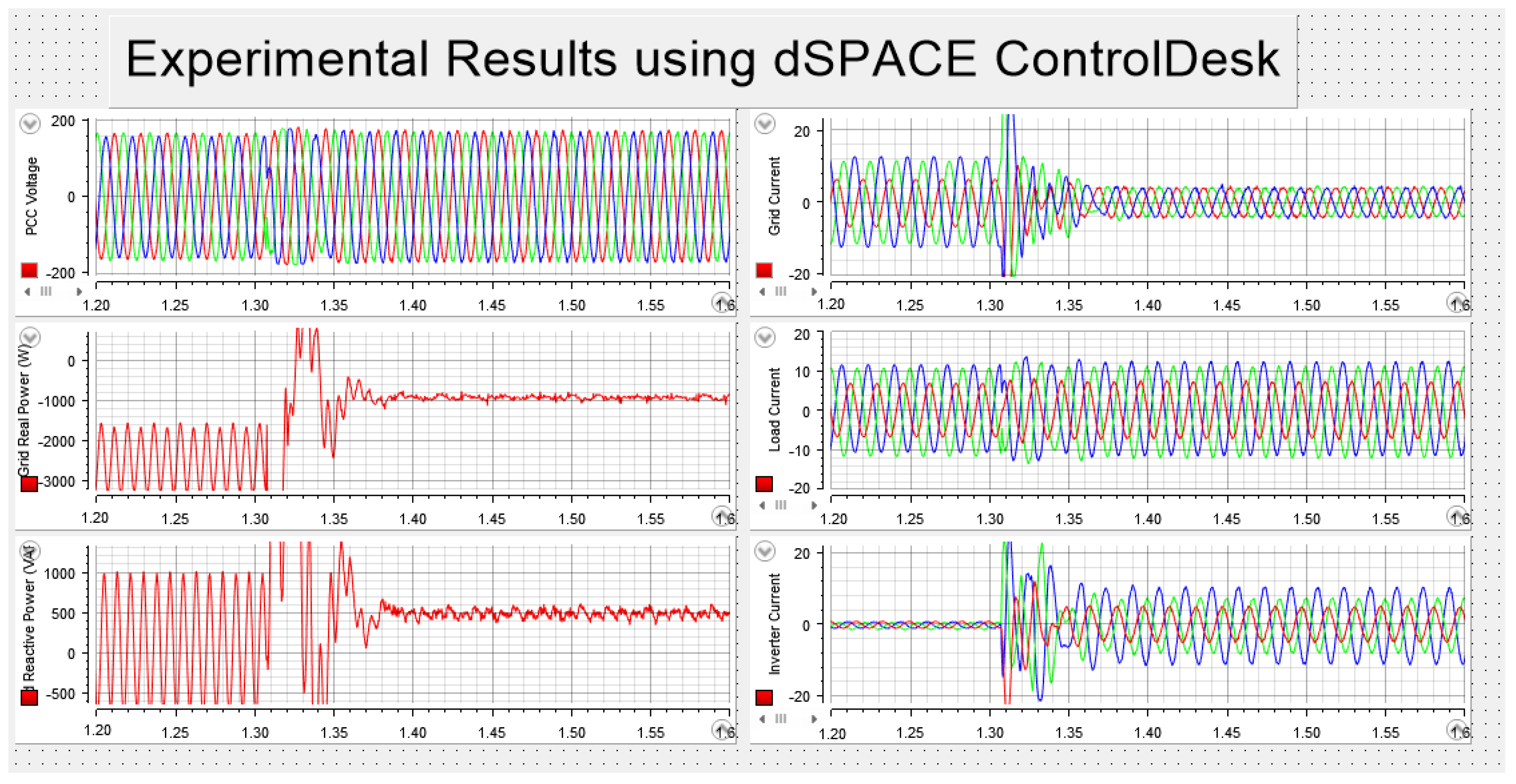
- The inverter was turned on with and equal to 2 kW and 0 var, respectively. The proposed method took a few milliseconds to balance and . The system can track the desired reference P and Q as shown in the dSPACE ControlDesk toolbox findings in Figure 26. Figure 27 shows the oscilloscope results for , , , , and . Grid current THD% is 2.59%. Figure 28 displays the experimental results utilizing the grid simulator NHR 9400 panel. The desired power has the opposite sign of the NHR 9400 readings ().
- At and , the suggested method can work in the four-quadrant power control mode in addition to balancing the three-phase grid currents and PCC voltages under an unbalanced three-phase load and unbalanced grid impedances. The experimental results using dSPACE Controldesk and grid simulator NHR 9400 are shown in Figure 29 and Figure 30, respectively. The THD% value of the grid currents is 2.3%. Note that the desired power has the opposite sign of the NHR 9400 readings ().
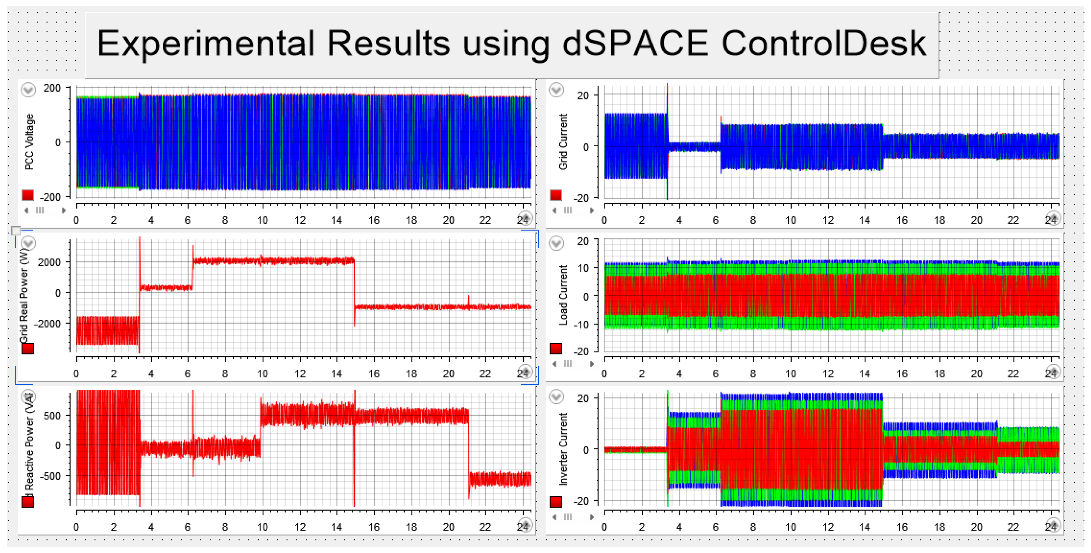
- As seen in Figure 31, various real and reactive power values were studied. At s, kW and var. Then, kW at s and kvar at s. At s, the desired power was set to be kW, and at s, kvar.
6. Conclusions
Author Contributions
Funding
Data Availability Statement
Conflicts of Interest
Abbreviations
| APF | Active power filters |
| DDSRF PLL | Decoupled double synchronous reference frame phase-locked loop |
| DPD-SR | Direct phase-angle detection |
| EPR | Enhanced proportional-resonant controller |
| ESS | Energy storage systems |
| MPRS | Modified PR control strategy |
| CPT | The conservative power theory |
| DQ | The synchronous reference frame method |
| PCC | Point-of-common-coupling |
| PI | Proportional-integral |
| PLL | Phase-locked loop |
| PQ | The instantaneous real and reactive power theory |
| PR | Proportional-resonant |
| RES | Renewable energy resources |
| SAPF-UOCM | Shunt active power filter using only current measurements |
| SCEM | Symmetrical component extraction method |
| SCEM-P | Symmetrical component extraction method using P controller |
| SCEM-PR | Symmetrical component extraction method using PR controller |
References
- Li, P.; Dan, B.; Yong, K.; Jian, C. Research on three-phase inverter with unbalanced load. In Proceedings of the Nineteenth Annual IEEE Applied Power Electronics Conference and Exposition, Anaheim, CA, USA, 22–26 February 2004; pp. 128–133. [Google Scholar]
- Pillay, P.; Manyage, M. Definitions of Voltage Unbalance. IEEE Power Eng. Rev. 2002, 22, 49–50. [Google Scholar] [CrossRef]
- Guan, M.; Xu, Z. Modeling and Control of a Modular Multilevel Converter-Based HVDC System Under Unbalanced Grid Conditions. IEEE Trans. Power Electron. 2012, 27, 4858–4867. [Google Scholar] [CrossRef]
- Tu, Q.; Xu, Z.; Chang, Y.; Guan, L. Suppressing DC voltage ripples of MMC-HVDC under unbalanced grid conditions. IEEE Trans. Power Deliv. 2012, 27, 1332–1338. [Google Scholar] [CrossRef]
- Li, M.; Chang, X.; Dong, N.; Liu, S.; Yang, H.; Zhao, R. Arm-Current-Based Model Predictive Control for Modular Multilevel Converter Under Unbalanced Grid Condition. IEEE J. Emerg. Sel. Top. Power Electron. 2021, 10, 3195–3206. [Google Scholar] [CrossRef]
- Choi, W.; Morris, C.; Sarlioglu, B. Modeling three-phase grid-connected inverter system using complex vector in synchronous dq reference frame and analysis on the influence of tuning parameters of synchronous frame PI controller. In Proceedings of the 2016 IEEE Power and Energy Conference at Illinois (PECI), Urbana, IL, USA, 19–20 February 2016; pp. 1–8. [Google Scholar]
- Liu, Y.; Bai, R.; Wang, D.; Ma, W.; Wang, L. Proportional-Resonant Control Method Of Three-Phase Grid-Connected Inverter. In Proceedings of the 26th Chinese Control and Decision Conference (2014 CCDC), Changsha, China, 31 May–2 June 2014; pp. 4797–4800. [Google Scholar]
- Kalaivani, C.; Rajambal, K. Grid Integration of Three-phase Inverter using Decoupled Double Synchronus Reference Frame PLL. In Proceedings of the 2019 International Conference on Computation of Power, Energy, Information and Communication (ICCPEIC), Piscataway, NJ, USA, 27–28 March 2019; pp. 221–226. [Google Scholar]
- Sadeque, F.; Benzaquen, J.; Adib, A.; Mirafzal, B. Direct Phase-Angle Detection for Three-Phase Inverters in Asymmetrical Power Grids. IEEE J. Emerg. Sel. Top. Power Electron. 2021, 9, 520–528. [Google Scholar] [CrossRef]
- Miletic, Z.; Tremmel, W.; Bründlinger, R.; Stöckl, J.; Bletterie, B. Optimal control of three-phase PV inverter under Grid voltage unbalance. In Proceedings of the 2019 21st European Conference on Power Electronics and Applications (EPE’19 ECCE Europe), Genova, Italy, 3–5 September 2019; pp. 1–11. [Google Scholar]
- Alathamneh, M.; Yang, X.; Nelms, R.M.; Al-Gahtani, S. Power Control of a Three-phase Grid-connected Inverter using a PI Controller under Unbalanced Conditions. In Proceedings of the SoutheastCon 2022, Mobile, AL, USA, 26 March–3 April 2022; pp. 447–452. [Google Scholar]
- Mortezaei, A.; Lute, C.; Simões, M.G.; Marafão, F.P.; Boglia, A. PQ, DQ and CPT control methods for shunt active compensators—A comparative study. In Proceedings of the IEEE Energy Conversion Congress and Exposition (ECCE), Pittsburgh, PA, USA, 14–18 September 2014; pp. 2994–3001. [Google Scholar]
- Akagi, H.; Watanabe, E.H.; Aredes, M. Instantaneous Power Theory and Applications to Power Conditioning; IEEE Press/Wiley-Interscience: Hoboken, NJ, USA, 2007. [Google Scholar]
- Marques, G.D. A comparison of active power filter control methods in unbalanced and non-sinusoidal conditions. In Proceedings of the IEEE 24th Industrial Electronics Conference, Aachen, Germany, 31 August–4 September 1998; pp. 444–449. [Google Scholar]
- Tenti, P.; Mattavelli, P.; Paredes, H.K.M. Conservative power theory sequence components and accountability in smart grids. Prz. Elektrotechniczny 2010, 6, 30–37. [Google Scholar]
- Al-Gahtani, S.; Nelms, R.M. A New Voltage Sensorless Control Method for a Shunt Active Power Filter for Unbalanced Conditions. In Proceedings of the 2019 IEEE International Conference on Environment and Electrical Engineering and 2019 IEEE Industrial and Commercial Power Systems Europe (EEEIC/ICPS Europe), Genova, Italy, 11–14 June 2019; pp. 1–6. [Google Scholar]
- Al-Gahtani, S.F.; Nelms, R.M. Performance of a Shunt Active Power Filter for Unbalanced Conditions Using Only Current Measurements. Energies 2021, 14, 397. [Google Scholar] [CrossRef]
- Alathamneh, M.; Yang, X.; Nelms, R.M.; Al-Gahtani, S. Power Control of a Three-phase Grid-connected Inverter using a Time-Domain Symmetrical Components Extraction Method under Unbalanced Conditions. In Proceedings of the IECON 2021—47th Annual Conference of the IEEE Industrial Electronics Society, Toronto, ON, Canada, 13–16 October 2021; pp. 1–6. [Google Scholar]
- Bak, Y.; Lee, J.-S.; Lee, K.-B. Balanced Current Control Strategy for Current Source Rectifier Stage of Indirect Matrix Converter under Unbalanced Grid Voltage Conditions. Energies 2017, 10, 27. [Google Scholar] [CrossRef]
- Mohammed, N.; Ciobotaru, M.; Town, G. Online Parametric Estimation of Grid Impedance Under Unbalanced Grid Conditions. Energies 2019, 12, 4752. [Google Scholar] [CrossRef] [Green Version]
- Chen, X.; Wu, W.; Gao, N.; Liu, J.; Chung, H.S.-H.; Blaabjerg, F. Finite Control Set Model Predictive Control for an LCL-Filtered Grid-Tied Inverter with Full Status Estimations under Unbalanced Grid Voltage. Energies 2019, 12, 2691. [Google Scholar] [CrossRef] [Green Version]
- Alharbi, M.; Isik, S.; Alkuhayli, A.; Bhattacharya, S. Power Ripple Control Method for Modular Multilevel Converter under Grid Imbalances. Energies 2022, 15, 3535. [Google Scholar] [CrossRef]
- Yu, Y.; Wang, Z.; Wan, X. Optimal Current Balance Control of Three-Level Inverter under Grid Voltage Unbalance: An Adaptive Dynamic Programming Approach. Energies 2019, 12, 2864. [Google Scholar] [CrossRef] [Green Version]
- Ma, W.; Ouyang, S.; Xu, W. Improved Frequency Locked Loop Based Synchronization Method for Three-Phase Grid-Connected Inverter under Unbalanced and Distorted Grid Conditions. Energies 2019, 12, 1023. [Google Scholar] [CrossRef] [Green Version]
- Wang, S.; Bao, D.; Gontijo, G.; Chaudhary, S.; Teodorescu, R. Modeling and Mitigation Control of the Submodule-Capacitor Voltage Ripple of a Modular Multilevel Converter under Unbalanced Grid Conditions. Energies 2021, 14, 651. [Google Scholar] [CrossRef]
- Tan, K.-H.; Lin, F.-J.; Chen, J.-H. A Three-Phase Four-Leg Inverter-Based Active Power Filter for Unbalanced Current Compensation Using a Petri Probabilistic Fuzzy Neural Network. Energies 2017, 10, 2005. [Google Scholar] [CrossRef] [Green Version]
- Shin, H.; Chae, S.H.; Kim, E.-H. Unbalanced Current Reduction Method of Microgrid Based on Power Conversion System Operation. Energies 2021, 14, 3862. [Google Scholar] [CrossRef]
- Nakadomari, A.; Shigenobu, R.; Kato, T.; Krishnan, N.; Hemeida, A.M.; Takahashi, H.; Senjyu, T. Unbalanced Voltage Compensation with Optimal Voltage Controlled Regulators and Load Ratio Control Transformer. Energies 2021, 14, 2997. [Google Scholar] [CrossRef]
- Najafi, F.; Hamzeh, M.; Fripp, M. Unbalanced Current Sharing Control in Islanded Low Voltage Microgrids. Energies 2018, 11, 2776. [Google Scholar] [CrossRef] [Green Version]
- Kim, J.-M.; Song, G.-S.; Jung, J.-J. Zero-Sequence Voltage Injection Method for DC Capacitor Voltage Balancing of Wye-Connected CHB Converter under Unbalanced Grid and Load Conditions. Energies 2021, 14, 1019. [Google Scholar] [CrossRef]
- Ahmed, E.M.; Aly, M.; Elmelegi, A.; Alharbi, A.G.; Ali, Z.M. Multifunctional Distributed MPPT Controller for 3P4W Grid-Connected PV Systems in Distribution Network with Unbalanced Loads. Energies 2019, 12, 4799. [Google Scholar] [CrossRef] [Green Version]
- Cai, H.; Zhang, P.; Zhao, H.; Shi, J.; Yao, W.; He, X. Controller design for three-phase inverter with power unbalanced loads applied in microgrids. In Proceedings of the 2015 IEEE Energy Conversion Congress and Exposition (ECCE), Montreal, QC, USA, 20–24 September 2015; pp. 4588–4593. [Google Scholar]
- Alathamneh, M.; Yang, X.; Nelms, R.M. Power Control of a Three-phase Grid-connected Inverter using a Proportional-Resonant Control Method under Unbalanced Conditions. In Proceedings of the IECON 2021—47th Annual Conference of the IEEE Industrial Electronics Society, Toronto, ON, Canada, 13–16 October 2021; pp. 1–6. [Google Scholar]
- Alathamneh, M.; Ghanayem, H.; Yang, X.; Nelms, R.M. PR Controller for a Three-phase Grid-connected Inverter in an Unbalanced System using a Time-Domain Symmetrical Components Extraction Method. In Proceedings of the 2022 IEEE 31st International Symposium on Industrial Electronics (ISIE), Anchorage, AK, USA, 1–3 June 2022; pp. 18–23. [Google Scholar]
- Pereira, L.F.A.; Bazanella, A.S. Tuning Rules for Proportional Resonant Controllers. IEEE Trans. Control. Syst. Technol. 2015, 23, 2010–2017. [Google Scholar] [CrossRef]
- Akagi, H.; Kanazawa, Y.; Nabae, A. Instantaneous reactive power compensators comprising switching devices without energy storage. IEEE Trans. Ind. Appl. 1984, 20, 625–630. [Google Scholar] [CrossRef]
- Duesterhoeft, W.C.; Schulz, M.W.; Clarke, E. Determination of Instantaneous Currents and Voltages by Means of Alpha, Beta, and Zero Components. Trans. Am. Inst. Electr. Eng. 1951, 70, 1248–1255. [Google Scholar] [CrossRef]
- Yang, X.; Alathamneh, M.; Nelms, R.M. Improved LCL Filter Design Procedure for Grid-Connected Voltage-Source Inverter System. In Proceedings of the 2021 IEEE Energy Conversion Congress and Exposition (ECCE), Vancouver, BC, Canada, 10–14 October 2021; pp. 3587–3591. [Google Scholar]


| f | Grid frequency | 60 Hz |
| Grid phase voltage | 120 V RMS | |
| Switching frequency | 5 kHz | |
| DC source voltage | 400 V | |
| Inverter side inductance | 2.3 mH | |
| Grid side inductance | 0.58 mH | |
| C | Filter capacitance | 15 μF |
| R | Damping resistor | 1.5 Ω |
| Resonant coefficient of PR controller | 1800 | |
| Proportional coefficient of PR controller | 2.25 | |
| Balanced grid Impedance for phases a, b, c | 4.2, 4.2, 4.2 mH | |
| Balanced grid Impedance for phases a, b, c | 5.1, 4.5, 3 mH | |
| Three-phase load | 8, 16, 32 Ω |
| Inductance (mH) | 1.7 mH | 1.5 mH | 1 mH |
| Core Type | 78100-A7 | 77102-A7 | 78100-A7 |
| Number of Stacks | 3 | 3 | 2 |
| Wire | AWG 12 | AWG 12 | AWG 12 |
| Number of Turns | 92 | 107 | 87 |
Publisher’s Note: MDPI stays neutral with regard to jurisdictional claims in published maps and institutional affiliations. |
© 2022 by the authors. Licensee MDPI, Basel, Switzerland. This article is an open access article distributed under the terms and conditions of the Creative Commons Attribution (CC BY) license (https://creativecommons.org/licenses/by/4.0/).
Share and Cite
Alathamneh, M.; Ghanayem, H.; Nelms, R.M. Bidirectional Power Control for a Three-Phase Grid-Connected Inverter under Unbalanced Grid Conditions Using a Proportional-Resonant and a Modified Time-Domain Symmetrical Components Extraction Method. Energies 2022, 15, 9564. https://doi.org/10.3390/en15249564
Alathamneh M, Ghanayem H, Nelms RM. Bidirectional Power Control for a Three-Phase Grid-Connected Inverter under Unbalanced Grid Conditions Using a Proportional-Resonant and a Modified Time-Domain Symmetrical Components Extraction Method. Energies. 2022; 15(24):9564. https://doi.org/10.3390/en15249564
Chicago/Turabian StyleAlathamneh, Mohammad, Haneen Ghanayem, and R. M. Nelms. 2022. "Bidirectional Power Control for a Three-Phase Grid-Connected Inverter under Unbalanced Grid Conditions Using a Proportional-Resonant and a Modified Time-Domain Symmetrical Components Extraction Method" Energies 15, no. 24: 9564. https://doi.org/10.3390/en15249564