
Selected Aspects of Decreasing Weight of Motor Dedicated to Wheel Hub Assembly by Increasing Number of Magnetic Poles


1
Łukasiewicz Research Network—KOMEL Institute of Electric Drives and Machines, 40-203 Katowice, Poland
2
Department of Electrical Engineering and Computer Science, Faculty of Electrical Engineering, Silesian University of Technology, 44-100 Gliwice, Poland
*
Author to whom correspondence should be addressed.
Energies 2021, 14(4), 917; https://doi.org/10.3390/en14040917
Submission received: 25 December 2020
/
Revised: 26 January 2021
/
Accepted: 1 February 2021
/
Published: 9 February 2021
(This article belongs to the Special Issue Design and Application of Electrical Machines)
Abstract
:Decreasing the mass of a wheel hub motor by improving the design of a motor’s electromagnetic circuit is discussed in this paper. The authors propose to increase the number of magnetic pole pairs. They present possibilities of mass reduction obtained by these means. They also analyze the impact of design changes on losses and temperature distribution in motor elements. Lab tests of a constructed prototype, as well as elaborated conjugate thermal-electromagnetic models of the prototype motor and modified motor (i.e., motor with increased number of magnetic poles) were used in the investigation. Simulation models were verified by tests on the prototype. Results of calculations for two motors, differing by the number of pair poles, were compared over a wide operational range specific to the motor application in the electric traction. A detailed analysis of the operational range for these motors was also made.
1. Introduction
Design of an electric motor dedicated for assembly in wheel hubs opens up a whole new vista of opportunities for the automobile industry. The new possibilities of such a solution include the elimination of elements of the drive mechanisms used to transfer the torque between the electric motor and the wheel, increasing the efficiency of the entire drive, as well as allowing for more dynamic driving and turning, and new designs of hybrid drives. Placing electric motors into wheels increases the amount of space available inside the vehicle where we may put additional batteries, so that vehicle range is significantly improved. Removing the power unit from the car’s body also allows for a more aerodynamic car design.
The use of this type of drive creates many challenges for motor designers. It should be remembered that electric motors mounted in wheels constitute an additional unsprung mass of the vehicle, which may affect the driving comfort and the vehicle’s steerability [1,2,3,4,5,6,7,8,9]. Therefore, the mass of the electric motor in such a drive solution should be as small as possible.
Additionally, if the driving characteristics of a car with wheel hub motors are to be comparable to ICE (internal combustion engine), or electric cars (with centrally mounted electric motors with gearboxes), the motor in the wheel hub must be characterized by a high maximum torque necessary for adequate acceleration, high long-term torque overload, enabling movement with the required speed on the slopes, and a sufficiently high rotation speed at maximum speed (to overcome the motion resistance at this speed). The electric motor should also be highly efficient in the entire operating range.
Designing an electric motor meeting all of these requirements is not easy due to the fact that the dimensions and weight of the motor are limited due to its location in the car.
The design of the motor for such application requires electromagnetic calculations and estimation of power losses, which are the reason for heating of various elements of the motor (especially the insulation of windings and permanent magnets), as well as the calculation of their temperatures.
The technical development of such electric motors requires large financial resources and multidisciplinary teamwork. The design guidelines set very high requirements for the operating parameters of the electric motor, while maintaining a relatively low weight. For this reason, the cooling efficiency must be extremely high. Appropriately selected materials should be used, which should meet the requirements in many physical aspects. The issue of optimization of the wheel hub motor structure and the selection of appropriate materials has been discussed by many researchers [10]. There are publications in which various types of electric motors of various designs are selected for use in vehicle drive wheels [11,12,13,14,15,16,17,18]. In industry, technologically advanced structures are most often permanent magnet synchronous motors with external rotors [19,20,21,22,23,24,25]. This is due to a number of advantages, including the ability to control such motors in which the field weakening method can be used. Another advantage of this design is the relatively high torque due to the large diameter of the air gap. Another factor is the shape of the motor (motor geometry); it is best suited for multi-pole magnetic circuit system. Researchers also undertake research on this subject; however, these are usually theoretical studies [26] or studies of electric motors with relatively low power, in which many design issues (construction, thermal problems) are not taken into account. It should be emphasized that, when developing electromagnetic circuits for electric motors with compact construction and high power densities, attention should be paid to many design features, such as dimensional limitations, careful selection of materials (ensuring adequate structural strength and thermal conductivity), and technological possibilities. In wheel hub motors, all of these aspects influence the temperature distribution of the electric motor components to a much greater degree than in standard electric motors, as they are motors with a relatively high power density in relation to their weight.
The development of wheel hub motors requires testing on prototypes. These tests allow you to solve many important questions related to, among others with unsprung mass, the solution of effective seals, the operation of electric motor elements related to different thermal expansion, taking into account the influence of additional power losses affecting the temperatures of the motor elements.
The authors of the article, based on their own research to date, indicate the direction of development of the construction of wheel hub motors. The goal is to reduce the mass of the motor by reducing the mass of the electromagnetic circuit. The prototype wheel hub motor SMzs200S32 produced in the Łukasiewicz Research Network—KOMEL Institute of Electric Drives and Machines, was used for the simulation and laboratory work. This electric motor weighs 36 kg. The assumed operating parameters were achieved, but the designers decided to make changes to reduce weight. In the performed tests and simulations, the impact of the proposed design changes on the temperature distribution in the electric motor was assessed. The simulation models used in this study were verified with measurements.
In the article, the authors focus on reducing the mass of the electromagnetic circuit, which is the heaviest part of the mass of the prototype wheel hub motor under consideration. The article does not discuss possible changes to the mechanical structure of the electric motor in order to reduce its weight.
Many scientific studies concern the problem of improving the design of permanent magnet motors with concentrated windings, which are commonly used in wheel hub motors, but only simulation models are regularly used in research. One of the possible methods of improving the motor structure is the appropriate selection of the number of slots depending on the number of pairs of magnetic poles [27,28]. This results in a reduction of losses in permanent magnets [29,30,31,32,33], as well as a reduction in the dimensions of electromagnetic circuits. Therefore, the total weight of the motor is also reduced. In their research, the authors used the existing SMzs200S32 motor prototype. Laboratory tests of this motor were used to calibrate the electromagnetic/thermal model of the motor generated in Ansys Motor-CAD software (Ansys Canonsburg, Pensylwania, USA). A new motor design was then developed, featuring an increased number of pole pairs. The simulation results obtained for this model were compared with the results for the prototype motor. In scientific publications and available technical studies, very little work on the directions of further development of electric motors in wheel hubs is based on laboratory measurements of prototype electric motors. Very high use of the electric motor’s electromagnetic circuit, resulting from the need to obtain high power with significantly limited dimensions, requires solving a number of issues related to the construction of seals, ensuring sufficiently high strength of structural elements, the use of a new generation of insulation materials with relatively high thermal conductivity, and the development of new production technologies. The authors, developing the coupled electromagnetic-thermal model for simulation studies, based on the prototype wheel hub motor built, in which all the previously presented issues were solved, which had a significant impact on the electromagnetic field, generated power losses and the temperature field. Then, the model was validated using temperature measurements with sensors installed in many places, both in the stator and in the rotor. Considerations regarding the improvement of the design of the considered type of engines, which are very often found in the literature, based only on mathematical models without prototypes and measurements, may only set certain trends. The procedure proposed by the authors leads to the development of a proposal for a new engine solution with a significantly reduced mass, supported by a verified thermal model. This method allows for a more accurate approximation of design solutions to be put into production.
2. Motor Construction
Multi-pole motors with external rotors are often used for assembly in EV wheels. This is due to the character of space in the wheel, where the motor is placed. The electromagnetic circuit of such a motor is toroidal, so that additional space found inside this toroid may be used. The cross-section of the three-dimensional (3D) model of the discussed SMzs200S32 motor is shown in Figure 1.
Most of the hull is the rotating element. It contains a magnetic core with mounted permanent magnets. The stationary element is the anchor disc with the supporting structure, in which there is a labyrinth cooling system. The stator’s magnetic core with winding is mounted on the supporting structure (Figure 1).
The motor is dedicated for assembly in a 17” wheel rim.
A rotor position sensor is required to control the motor. Typically, an incremental encoder is used.
The space in which the electric motor must fit is limited by the dimensions of the wheel rim (outer diameter and motor length), while the inner diameter depends on how the space inside the toroid is used. In the case of the presented structure, this space houses the vehicle brake drum.
The space containing the electromagnetic circuit is limited by the dimensions of the support structure, anchor shell, and rotor, which must be thick enough to ensure the required mechanical strength (Figure 1).
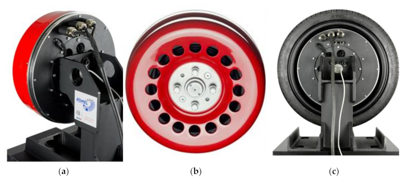
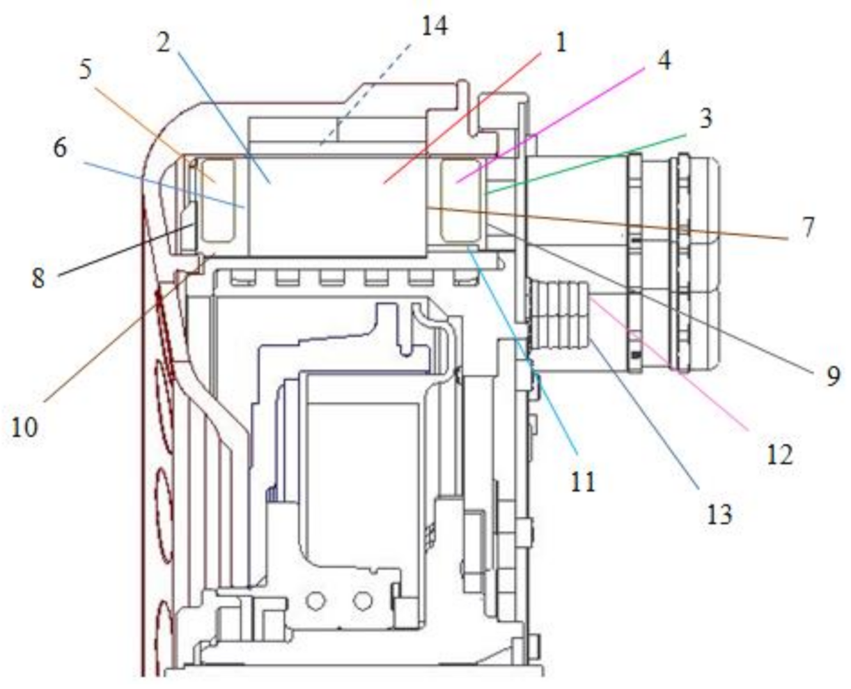
Pictures of the prototype SMzs200S32 motor are shown in Figure 2. For research purposes, this motor was equipped with a number of PT100 temperature sensors, placed in various elements of the stator and rotor (permanent magnets). Additionally, a small wireless temperature recorder was developed. It is installed on the rotor surface and the sensor mounted on the magnet is connected to the recorder. Temperature can be registered continuously and data are sent wirelessly [34]. The cross-section of the motor with the positions of the temperature sensors is shown in Figure 3.
Motor at the test stand was supplied from Sevcon Gen4 Size8 inverter dedicated to EV supply. During tests, the inverter was supplied with nominal voltage V = 350 VDC (about 235 V at motor terminals). Since the rotor position angle sensor had to be used, a magnetic absolute encoder with analog Sin–Cos output was applied. Control of the motor drive was conducted with the help of a computer-aided measurement and control device with dedicated control.
The motor operates in two zones: constant torque zone and field weakening zone. The rated operational parameters of this motor are presented in Table 1.
The operating parameters of the electric motor make it possible to use it in various car drive systems, where two, four, or more electric motors can be used. Taking the example of a Fiat Panda car with two motors, assuming a car weight of 1600 kg and driving at a speed of 150 km/h, each motor must be able to produce a torque of 150 Nm. When going up a 10% gradient at 105 km/h (950 rpm), each motor must generate a torque of approximately 300 Nm. The rated duty point allows the car to be driven continuously (i.e., until the supply battery is fully discharged) at a speed of more than 115 km/h on a road with a slope of 15.5%. This is a very abstract operating point because continuous operation under these conditions (road gradient, speed) is highly unlikely.
In the case of investigated drive, the maximum torque is limited by peak value of inverter current (seen from motor terminals). This specific inverter was used in tests. Further discussion will relate to simulation of motor operation within full operational range, this limitation will be ignored.
The wheel hub motor SMzs200S32 meets the operating parameters assumed by the constructors, but the authors planned to reduce its weight. For this purpose, an electromagnetic circuit with an increased number of pole pairs has been proposed. The further part of the article presents the procedure for modifying the design of the electromagnetic circuit using the calculation models generated in the Ansys Motor-CAD program.
3. Computational Models
If we aim to decrease the motor mass, then, apart from the use of lightweight and resistant material for the supporting structure, housing, and anchoring shield, the mass of the electromagnetic circuit should be decreased as much as possible (this mass usually constitutes more than 50% of the total motor mass). In the design, we should try to obtain a reasonably high number of poles, because this will decrease the volume of the electromagnetic circuit on account of lower magnetic flux within a single pole. Thus, the width of the stator yoke and the rotor of the electromagnetic circuit may be significantly diminished. This will result in a better ratio of core volume (or mass) to rated torque. Use of winding with concentrated coils is also useful, because winding ends may be reduced.
When we consider possibilities of lessening mass of the electromagnetic circuit by increasing the number of pole pairs, different existing limitations must be examined. Increasing the number of poles in SPM (Surface Permanent Magnet Motor) motors is easy from a technological standpoint, but it may be restricted by minimum dimensions of a single magnet (technological possibilities of mounting small magnets). The other limitation is maximum output frequency of supply inverter. We must also keep in mind that, when yoke thickness is reduced, the mechanical strength of the rotor also goes down.
An additional problem emerges when we try to increase the number of stator slots in proportion to the increased number of poles. For instance, with the number of poles 2p = 32 and number of slots Qs = 48, the number of slots per pole per phase is q = 0.5. If we raise the number of poles up to 2p = 56, then in order to maintain q = 0.5, the number of slots should be increased to Qs = 84 (Figure 4). Since the outer diameter of the machine is constant, such a large number of slots may not be feasible due to the technological limitations of production machines, the strength of the thin stator teeth, or the workability of the winding. In addition, the cost of producing a winding will also increase, as the number of coils is much greater. The area of the active part of the slot winding also decreases, because, with the increase in the number of slots, the share of slot insulation is greater.
In this situation, it is possible to reduce the number of sockets per pole per phase, but it should be remembered that, for motors with q < 0.5, the spatial distribution of magnetomotive force mmf is deformed, which causes increased eddy current losses in permanent magnets [35].
The winding temperature limited by the permissible winding insulation temperature is a standard torque limiting factor in electrical machines. In the case of multipole motors, and in particular when the number of gaps per phase per q pole is equal to or less than 0.5, the increased power losses in permanent magnets may lead to a situation, where the magnet temperature will limit the maximum load of the motor (especially when the motor is running with field weakened to increase the speed range [36]). Under field weakening conditions, magnets are exposed, not only to an increase in temperature caused by the magnitude and frequency of the supply current, but also to an external magnetic field.
By increasing the number of pole pairs, we obtain a toroidal motor with an increased internal diameter. As a result, the weight is reduced and additional space is gained inside the motor, which can be used, for example, for mounting a car brake drum (Figure 1).
The used Ansys Motor-CAD software (Ansys Canonsburg, Pensylwania, USA) greatly supports the design of electrical machines, because work simulations can be carried out in the entire working range of torque and speed.
At the same time, it is distinguished by very high computing speeds. It is possible to solve conjugated electromagnetic and thermal fields. It uses a combination of advanced analytical equations and calculations based on 2D FEM. The temperature can be determined in steady and transient conditions; the program uses advanced models in the form of thermal networks [37,38,39,40,41,42].
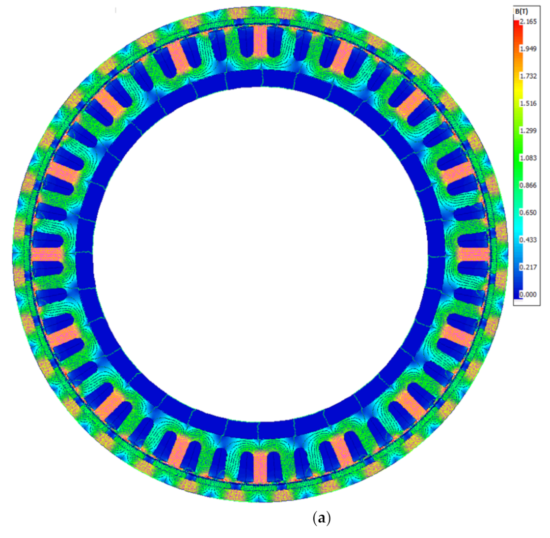
Model 1 of the motor with the number of pole pairs 2p = 32, where the number of slots per pole per phase is q = 0.5, is a representation of the prototype SMzs200S32 motor. Then the model of Motor #2 was developed; with the number of poles increased to 2p = 56, the number of slots per pole per phase also changed: q = 0.375. Modification of the electromagnetic circuits was carried out to maintain the outer diameter of the rotor and the width of the air gap. The width of the magnet in Motor #2 also increased from 4 to 5 mm. This was at the expense of the rotor yoke. As a result, the inside diameter of the stator and the diameter of the air gap were increased. The calculated operating parameters of both the motors and the masses of individual elements of the electromagnetic circuits are presented in Table 2. The weight of the winding and the mass of the magnetic core were reduced as assumed. The flux density in the rotor’s magnetic core increased with increasing width of the permanent magnet (at the expense of the core width). The weight of the winding was reduced by 0.9 kg, the mass of the stator magnetic core by 2.3 kg, the mass of the rotor magnetic core by 2.1 kg, and the mass of permanent magnets increased by 0.66 kg.
The simulation models and the calculated flux density distribution from the permanent magnets in the magnetic core are shown in Figure 5.
The calculations were made for the given power supply parameters, which are dictated by the permissible operating parameters of the inverter UDCmax. = 350 V, Imax. = 350 A. The control system performs work in two zones, the work zone with constant torque and the work zone weakening the magnetic field from permanent magnets.
Thermal calculations were made using two models in the thermal of the Motor-CAD module.
As the stator inner diameter increases, the diameter of the stator support structure increases. It was assumed that the thickness of the support structure must be kept so that its internal and external diameter change with the increase of the internal diameter of the stator.
The dimensions of the cooling channels remain unchanged. To facilitate further analysis, both models have identical lengths of winding ends. Note that in Motor #2, the calculated length of the turns is smaller and the teeth of the stator core are narrower. In practice, this can lead to a reduction in the length of the winding ends and a reduction in the length of the entire motor, which will also reduce the weight of the motor further. Determining the length of winding ends requires carrying out technological tests on the physical execution of the prototype winding, which is currently not the subject of research.
The simulation model uses the parameters of the actual materials used in the construction of SMzs200S32: electrical sheets used for stator and rotor laminates, permanent magnets, and aluminum alloy.
To sum up, the mass of the electromagnetic circuit of engine 2 is 4.7 kg less (by 23.5%), while the mass of its supporting structure is 0.3 kg greater than that of motor no. 1. The total mass of Motor #2 in relation to Motor #1 was significantly reduced—by 4.4 kg (by 12%).
The Bertotti method was used for calculating the magnetic core power losses in the elaborated models [43,44,45,46]. This lets us account for hysteresis, eddy current, and excess losses:
where: kh—hysteresis factor, Bm—flux density, f—frequency, σ—conductivity, b—thickness of single electrical sheet, ke—excess loss coefficient.
The first part of the formula relates to hysteresis losses (due to the hysteresis loop of the ferromagnetic material of the magnetic core). The second part of the formula covers eddy current losses (eddy currents are induced in the magnetic core). The third part relates to excess losses, caused by interaction of the external magnetic field and local magnetic fields generated by eddy currents.
In analysis, copper losses are split into constant losses and losses due to skin effect, i.e., in the program named as AC winding losses. Copper losses are calculated on the basis of a well-known relationship:
where: IRMS-value of supply root mean square current, R(υ)—winding resistance as a function of temperature
AC Losses on AC windings can be determined by two methods—full FEA and hybrid FEA method. The full FEA method uses an accurate model where the induced eddy currents and then losses are calculated separately for each conductor. Obviously, this is the most time consuming method. Hybrid FEA uses the flux density levels calculated by FEM for each slot, and then the losses are calculated analytically. This method is quick, but much less accurate at relatively high frequencies and relatively large conductor cross-sections. In our case, the mixed method was adopted. For the operating point with maximum speed and load, the losses were calculated using both methods, and then the correction factor was calculated according to the formula:
where: AC winding losses calculated by Full FEA method, —AC winding losses calculated by hybrid FEA method.
Since further analysis takes into account a wide load/speed range, AC winding losses are calculated with hybrid FEA method and each result is then multiplied by correction factor.
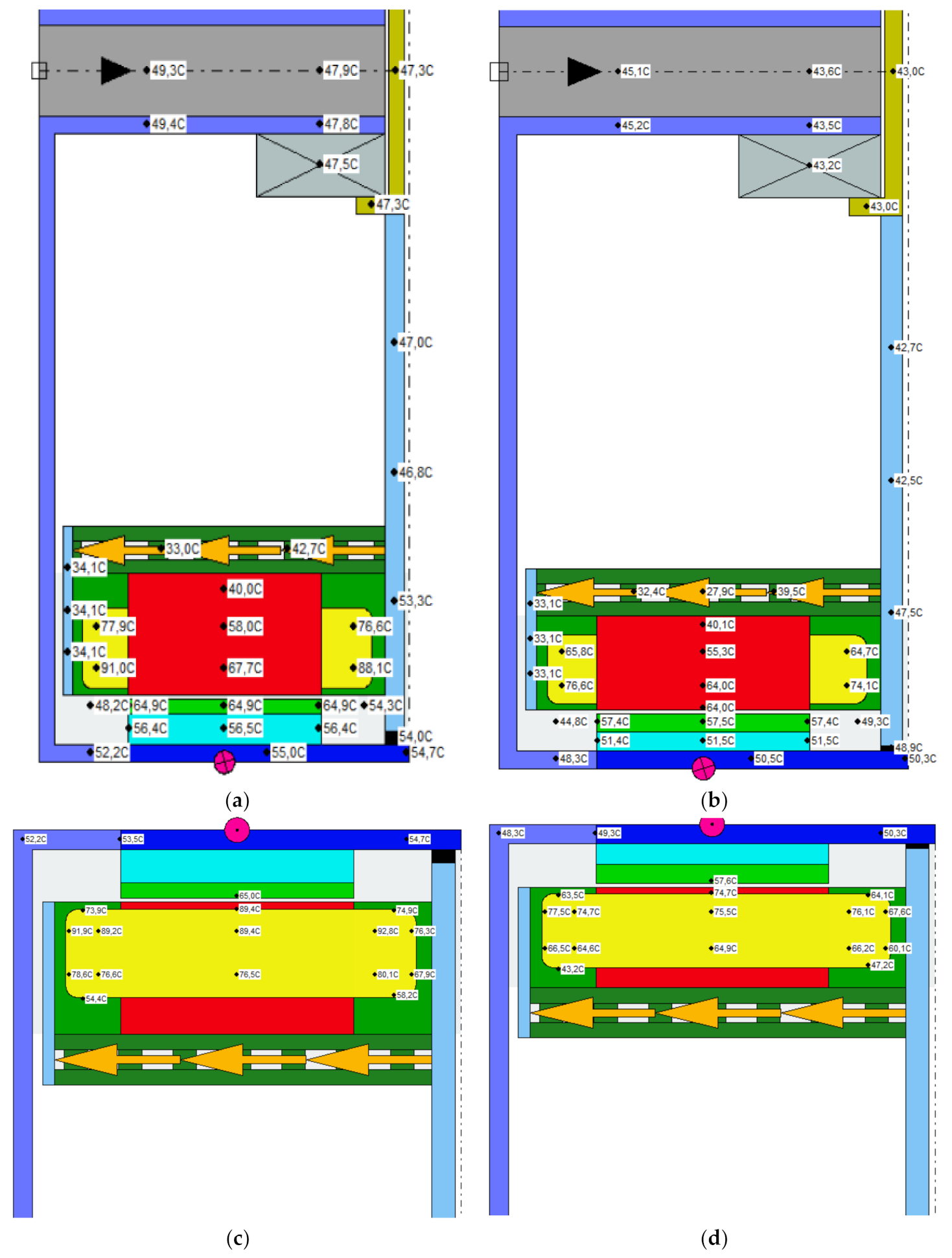
One operating point, motor SMzs200S32, was selected to verify the calculations. The operational parameters as well as losses and temperature distribution were tested. The work point was analyzed with the current consumption root mean square IRMS = 109 A and the rotational speed 950 rpm. With two motors mounted on the 17-inch wheels of the Fiat Panda, this point corresponds to driving at 100 km/h on a steep road (10% gradient). The values of coolant flow (10 L/min), coolant temperature (23.8 °C) and ambient temperature (28.3 °C) used in the calculations are identical to those measured in the laboratory tests. Table 3 summarizes the different operating parameters of the three motors: the real SMzs200S32 prototype motor, the Motor #1 simulation model, which is a representation of the prototype, and the Motor #2 simulation model, which is a version of the motor with an increased number of magnetic poles. Motor #1 and Motor #2 are shown in Figure 6 and Figure 7 with the calculated temperatures marked.
Based on the data from Table 3 and Figure 6, it is possible to see the importance of the position of the temperature sensor in a given element of the electric motor. In the case of a physically manufactured motor with a “compact” design, it is rather difficult to locate a large number of temperature sensors and their terminals. In addition, the stator of the motor, which houses almost all sensors, is embedded in epoxy. This excludes the possibility of replacing the sensor or changing the location. Since the gap-filling factor is high (approximately 75% with insulation) and due to the winding technology, the temperature sensors in the slots are placed on its bottom during the winding process. On the other hand, the sensors at the winding ends are placed in the middle. When the measured and calculated steady-state temperatures for the operating point in question are compared, we can see that model Motor #1 provides sufficient accuracy. The temperature differences between the prototype motor and Motor #1 result from the simplification of the shapes, possible slight differences between the physical parameters of the materials adopted in the model and the actual ones occurring in the motor (this may be due to technological differences) and the inaccuracy of determining the contact resistance between motor elements. The temperature comparison shows that an increase in the number of pole pairs (motor 2) lowers the temperature of the winding and magnets.
4. Discussion Calculation Results—Comparison of Operational Parameters of Investigated Motors
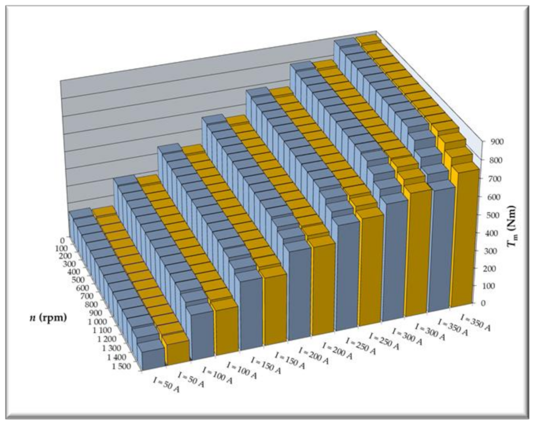
During subsequent analysis, we calculated operational parameters over a wide range of rotational speed and supply current IRMS. In order to take into account differences between two designs (and these differences have impact on temperature), comparison of operational parameters was conducted with temperatures calculated for current IRMS = 150 A and speed n = 1000 rpm. In all bar graphs, results for Motor #1 and Motor #2 are marked in blue and yellow, respectively. Rotational torque versus speed is shown in Figure 8.
In the first control zone, Motor #2 attains somewhat smaller rotational torques than Motor #1 (for identical supply currents). When the current is increased, then torque becomes comparable or higher. In the second control zone, when the field is weakened, Motor #2 is characterized by rotational torque equal or slightly higher than that of Motor #1.
Keeping in mind the planned later analysis, which would compare the different types of losses for the two motors (copper losses, losses in the magnetic core, and losses on permanent magnets), and these losses depend on the value of the supply current, we made calculations with the operating torque as the input quantity. The calculated torque characteristics are shown in Figure 9, and the corresponding supply current characteristics in Figure 10.
Basing on characteristics shown in Figure 9, we may say that, for higher rotational torques, operational range of Motor #1 is slightly less than that of Motor #2. This is because the supply voltage of the electric drive for both motors is the same UDC = 350 V. Motor #1 starts to work in the magnetic field weakening control zone in relation to Motor #2 slightly earlier (as shown in Figure 10, Motor #1 currents increase a little earlier at higher rotational speeds), while with increasing load torque, more current power is field weakening, and not generating torque.
Keeping in mind that these motors are dedicated to an electric car drive (modified Fiat Panda car) with two motors, the less extensive range of rotational torque may be of minimal importance in the first control zone, since it may affect car acceleration to some extent. In the second control zone, especially at maximum speeds, rotational torques of 750 Nm range practically do not occur.
Characteristics of supply currents versus assumed rotational torques are shown in Figure 10. The supply currents of two motors are not identical, and their disparity increases as rotational speed goes up and we enter the second control zone. As in the case of calculation results shown in Figure 8, we may state that equalization of the rotational torque in the first control zone has led to an increase in the supply current of Motor #2. In the second control zone, and as the field becomes more weakened, Motor #1 must be supplied with a higher current in order to maintain rotational torque at the required level.
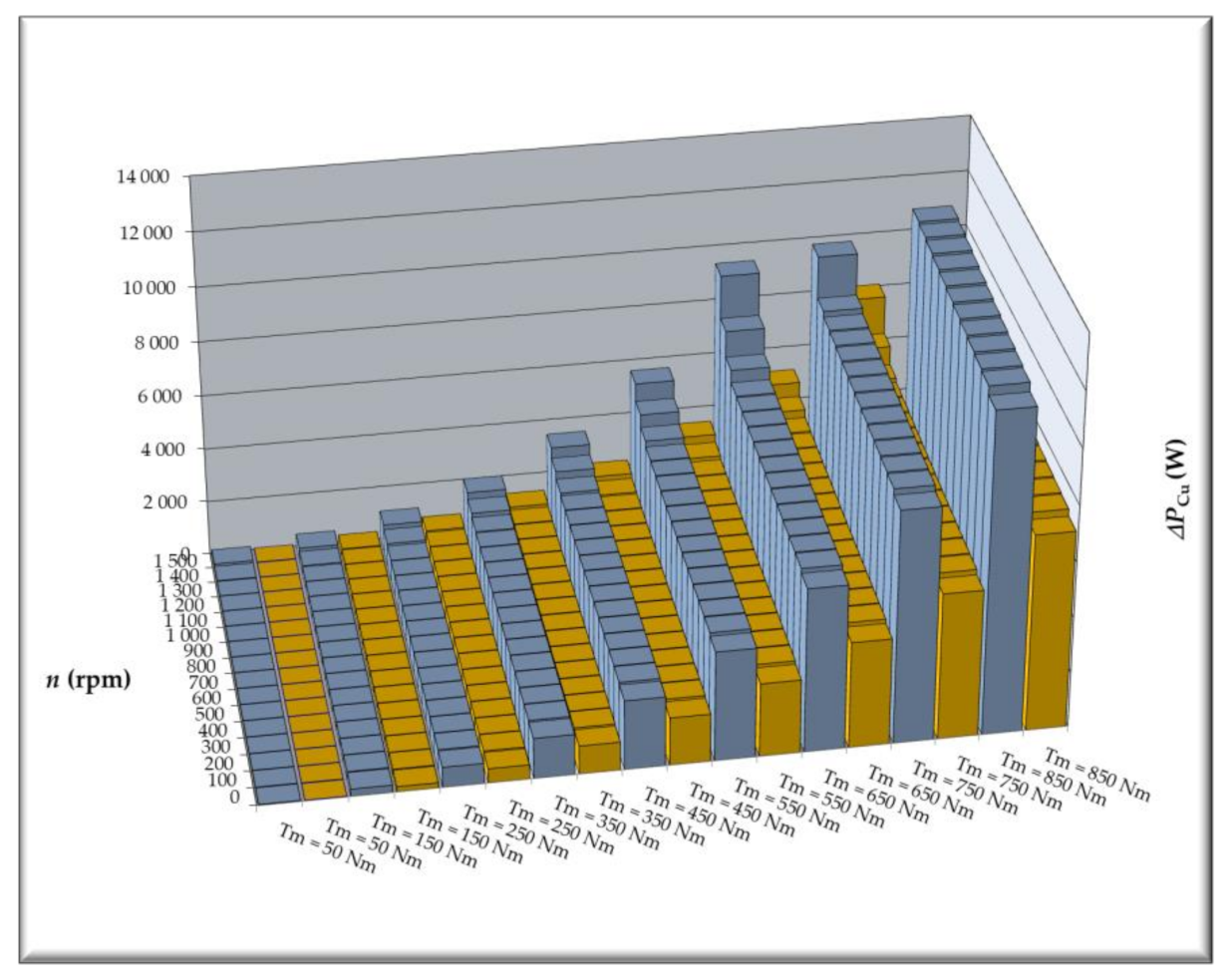
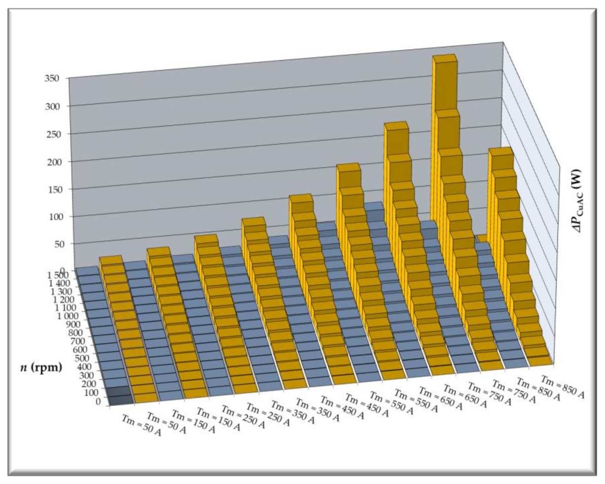
Characteristics shown in Figure 11 confirm the fact that Motor #1 is characterized by higher winding losses over the entire operational range. This is due to greater winding resistance and higher winding operational temperatures. Power losses associated with current displacement effects, i.e., AC winding losses, are shown separately in Figure 12. In this case, higher losses are clearly generated in Motor #2 windings; this is supplied at a much higher frequency since the number of pole pairs is increased from p = 16 to p = 28, and speed range remains unchanged. Even though AC winding losses are higher, their contribution to total losses (Figure 11) is insignificant.
Calculated total losses in the stator core are shown in Figure 13. Losses in Motor #2 core are greater than those of Motor #1 on account of higher values of flux density (produced by permanent magnets) in the electromagnetic circuit (see Figure 5) and higher supply currents (Figure 11). We may observe in these curves that core losses increase as rotational speed increases and then they stabilize at more or less constant levels; this is due to field weakening and operation in the second control zone. The field weakening zone for Motor #1 is commenced somewhat earlier.
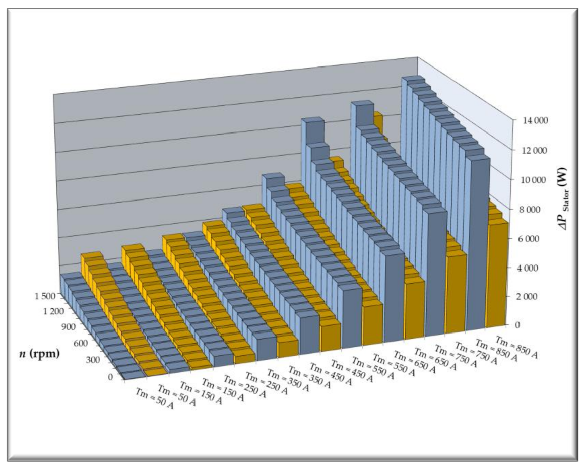
Characteristics of calculated stator total losses are presented in Figure 14; this is the sum of losses shown in Figure 11 and Figure 13. It must be noted that these losses determine temperature distribution in the stator core. The stator core is heated by its own losses and winding losses, which are transferred through the core to the coolant. In the case of lowest loads (rotational torque Tm = 50 Nm) losses of Motor #2 are higher over the entire range of rotational speed. These are mostly losses generated in the stator’s magnetic core; throughout the entire operational range, these losses are higher in Motor #2 (Figure 14). As the load increases, winding losses increase in both motors, but winding losses in Motor #1 increase at a much higher rate (see Figure 11), while stator core losses do not vary much with changes in the current. When charts for different losses are compared, we observe that while load increases, the area where Motor #2 losses are lower than Motor #1 losses moves away from lower speeds towards maximum speed. In the case of rotational torque equal to Tm = 450 Nm, total losses generated in the motor stator are higher in Motor #1 over the entire rotational speed range. When load is increased, difference in stator’s total losses also grows.
Permanent magnet losses also have significant impact on the motor’s operational range and these losses will be investigated next. PM losses are shown in Figure 15.
Examining the bar chart presented in Figure 15, we may observe that over (nearly) the entire operational range, PM power losses are smaller in Motor #2; the difference is increased as rotational speed rises (this is true with exception of operating points at speed n = 1500 rpm and at loads up to Tm = 150 Nm). Publications on the subject make it evident that decrease in number of slots per pole per phase results in increased PM losses [47]. Still, it must be pointed out that Motor #2 differs from Motor #1 by the number of magnetic pole pairs positioned upon diameter of similar size; this is related to significant decrease in PM angular length, so, finally, PM losses are lessened.
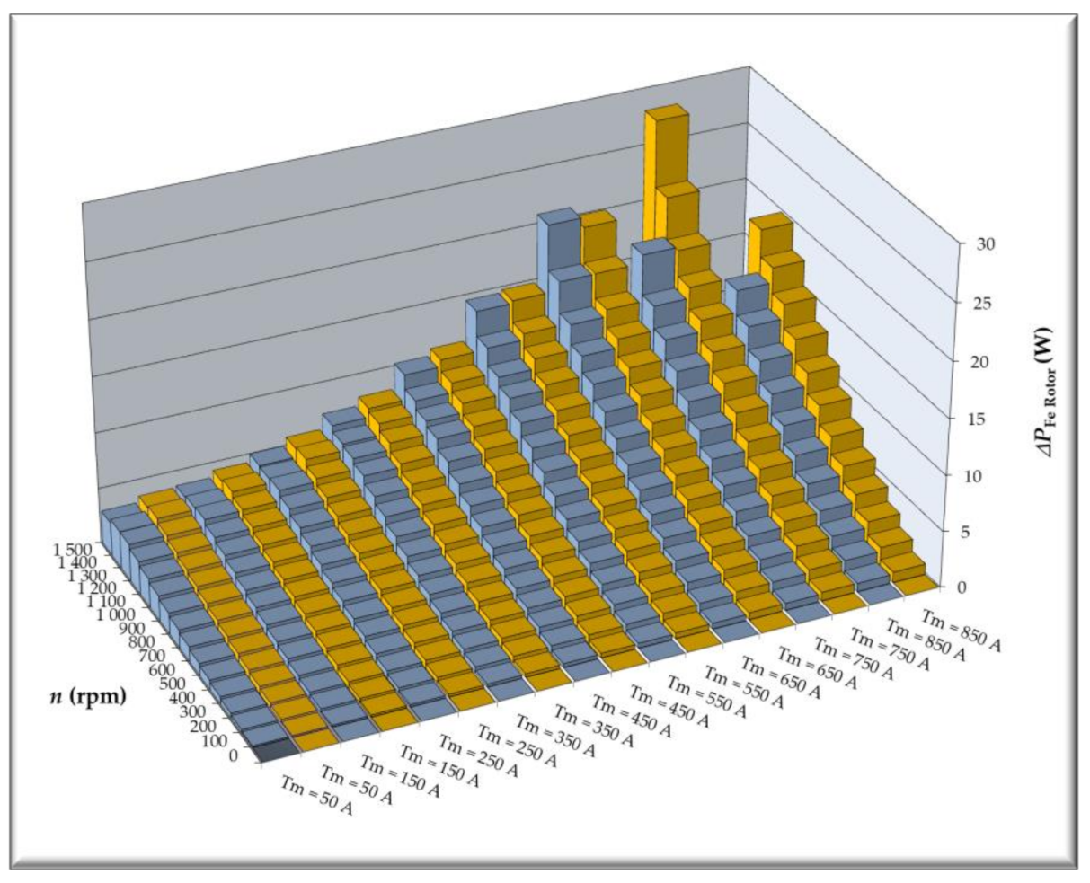
Characteristics of calculated rotor core losses are presented in Figure 16.
Rotor magnetic core losses are higher in Motor #2; still, value of these losses in relation to remaining rotor power losses, including PM losses, is very small.
Temperature rise in motor elements is influenced by the ratio of existing power losses to the area of heat removal. Design of Motor #2, with respect to Motor #1, is characterized by greater stator diameter and diameter of structure containing a water-cooling system. Thus, while lengths of both motors are identical, the area of heat removal is greater in Motor #2.
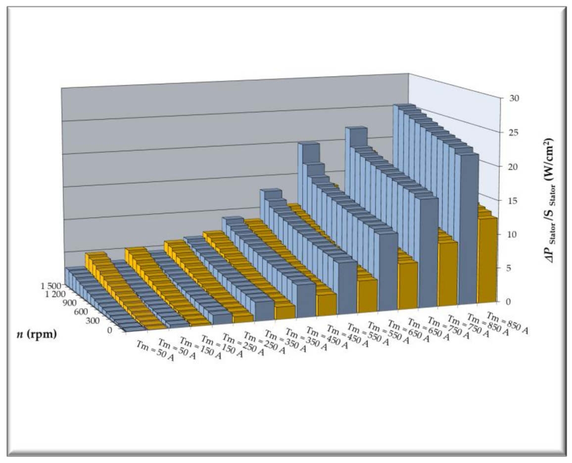
Bar charts showing the ratio of stator total losses to area of structure, where stator is positioned, are presented in Figure 17. If we compare losses shown in Figure 14 charts, with charts showing the ratio of these losses to the heat removal area (Figure 17), then we see that Motor #2 is much more promising; this is especially noticeable in the case of maximum speed at load torque equal to Tm = 450 Nm and Tm = 350 Nm.
A similar comparison was performed for winding losses in Figure 18. Total slot area is much greater in Motor #2 (SQ = 3389.4 cm2) than in Motor #1 (SQ = 235.6 cm2).
Ratio of power losses generated in permanent magnets to the rotor surface area where magnets are mounted is shown in Figure 19. The ratio of PM loss to heat removal area again underlines the advantages displayed by Motor #2, with respect to Motor #1.
In order to compare properties of these two motors, and taking into account the fact that cooling systems of the two motors differ since dimensions of structural elements are not identical, calculations were conducted for the S1 duty cycle, assuming that steady-state winding temperature cannot exceed TCu = 150 °C, while steady-state temperature of permanent magnets cannot exceed Tmag. = 100 °C. Ansys Motor-CAD (Ansys Canonsburg, Pensylwania, USA) analysis used here was based on the electromagnetic circuit model as well as the thermal model. The conjugated thermo-electromagnetic model was solved by the iterative method for speed, ranging from n = 0 rpm to n = 1500 rpm. Calculated torque-speed curves of the motors are shown in Figure 20; these have been worked out adopting the previously stated assumptions related to allowable steady-state temperatures for winding and permanent magnets.
The presented curves demonstrate clearly the advantage of Motor #2. Under the assumed conditions (maximum allowable temperatures of winding and magnets), the continuous torque of this motor is greater over the entire speed range than torque generated by Motor #1. In accordance with calculated power losses, difference in rotational torque becomes smaller as speed increases. Curves of maximum steady-state temperatures in winding, magnets, and magnetic core teeth of the stator are shown in Figure 21.
The calculated curves show that winding temperature determines the limits of the motor’s continuous operation. The exception is the operational point of Motor #2, at speed n = 1500 rpm, where winding temperature does not attain allowable temperature TCu < 150 °C, while permanent magnet temperature is equal to allowable temperature Tmag. = 100 °C. When rotational speed rises above c. n = 1200 rpm, the temperatures of magnet and stator’s core teeth stop increasing, and in case of Motor #1, they even start to decrease. Calculated winding losses, stator core losses and permanent magnet losses for limit motor load are shown in Figure 22. When we analyze the curves of calculated steady-state temperatures and corresponding power losses, we may observe that Motor #2 may operate continuously with much higher power losses in windings and core, generating higher rotational torque. At the same time, winding temperature is maintained at TCu = 150 °C. When rotational speeds are higher and motors operate with weakened magnetic field, this impact is more perceptible in Motor #1, where magnetic core and permanent losses are noticeably decreased, which results in a decrease of magnet temperature. When speed is maximum, winding losses are almost identical in both motors; the same is true for magnet losses. Losses in the stator core are greater in Motor #2.
Supply current (RMS) curves for Motor #1 and Motor #2 are shown in Figure 23.
5. Conclusions
The proposed electric motors intended for installation in a vehicle wheel must meet a number of requirements. One requirement is to reduce the weight of the motor so that the unsprung mass can be reduced. The research described was aimed at checking the possibility of reducing the mass by increasing the number of magnetic poles and increasing the width of the magnet at the expense of the rotor yoke. Model tests fully confirmed our expectations. Increasing the number of poles from 32 to 56 reduced the mass of the motor’s electromagnetic circuit: from 20.0 to 15.3 kg, i.e., by 23.5%. Models used for electromagnetic and thermal calculations were generated in Ansys Motor-CAD software (Ansys Canonsburg, Pensylwania, USA). The models are conjugated, so that interaction of electromagnetic field and thermal field may be taken into account. Motor #1 model is a representation of prototype SMzs200S32 motor designed and built in Łukasiewicz Research Network—Institute of Electrical Drives and Machines KOMEL. Motor #2 model is a modification of Motor #1 model, number of magnetic poles is increased. Number of slots per phase per pole was also modified, from q = 0.5 to q = 0.375.
The calculations show that, in spite of a significant decrease in mass of the electromagnetic circuit, Motor #2 is characterized by improved thermal parameters.
By increasing the number of pairs of magnetic poles and the volume of the permanent magnet, the allowable constant torque of Motor #2 increased. Despite the significant increase in the power frequency and the consequent increase in the losses in the magnetic core, the reduction of power losses in the winding and the geometric changes in the cooling system were much more important. The presented characteristics show that the total losses in the stator are largely lower in Motor #2. The higher losses in the stator are taken by Motor #2 at high rotational speeds and low and medium torques, which is also visible in the operating point parameters in Table 3, where Motor #2 has a slightly lower efficiency. By illustrating this operating point on the stator accumulative loss graphs, you can see that this is the area where Motor #2 has slightly higher accumulative losses. Observing the changes in the stator total loss ratio in both motors, it can be seen that, at higher rotational speeds, the effect of high frequency is significant at higher rotational speeds and lower supply currents. The effect of the frequency losses decreases as the overall winding losses increase. The total losses in the winding change with the current intensity and only negligibly with the frequency (due to the relatively small AC losses in the winding).
The temperature of the stator core drops; this is due to a decrease in the winding losses transferred to the core and an increase in the heat dissipation surface (caused by an increase in the diameter of the stator support structure). The losses of permanent magnets are smaller in Motor #2, regardless of the increase in frequency, due to the much smaller angular dimension of the magnets. In addition to the calculated power losses converted into heat, the temperature of the motor components is influenced by the dimensions of the cooling system. Design modifications introduced in the motor increase the heat dissipation area in the stator (increased internal diameter of the stator) and permanent magnets (increased rotor diameter on which the magnets are mounted). In addition, it should be noted that when we reduce the width of the stator and the rotor yoke, the thermal resistance between the winding and the cooling system housing and between the permanent magnets and the rotor outer surface is also reduced. The reduced stator yoke leads to a reduction in the distance between the coil terminals and the cooling system, which in turn leads to a reduction in the thermal resistance of the epoxy resin layer interposed between these elements. As a consequence, the heat dissipation from the winding part, which is characterized by the highest temperature in standard electric machines, improves [48,49].
Motor-CAD iterative calculations allowed the comparison of the torque vs. speed curves (maximum continuous torque), assuming that the winding and magnet temperatures did not exceed TCu = 150 °C and Tmag. = 100 °C, respectively. Motor #2, showing greater total losses at high rotational speeds, is characterized by a higher torque (in the S1 duty cycle) in the entire rotational speed range.
An additional advantage resulting from the increased number of pole pairs and the internal diameter of the stator is the distance of the motor structure from the brake drum (it is an additional source of heat during braking).
It should be noted that the power losses generated in the permanent magnets of the motor and the magnetic core can be further reduced by using permanent magnet segmentation and electrical sheets with a lower loss (we took M300-35A sheets in our calculations).
Apart from reducing the mass of the electromagnetic circuit, it is also necessary to analyze the possibilities of reducing the mass of the motor by reducing the mass of other elements, for example, by using light and durable materials [50].
The authors are currently exploring further options for reducing engine weight by improving cooling efficiency. The developed designs will allow better use of the electromagnetic circuit, which should result in a reduction of the engine weight while improving operating parameters.
Author Contributions
P.D.—development of computational models, running simulation, designing electromagnetic circuits, analysis of simulation results, preparation of the article. R.K.—analysis of simulation results, participation in the creation of proposals, editorial article. All authors have read and agreed to the published version of the manuscript.
Funding
The research is co-financed under the Program of the Ministry of Science and Higher Education “Implementation Doctorate” (POLAND). The research is a continuation of the project “Innovative Solutions for Direct Drive of Electric Vehicles”, financed by National Centre for Research and Development under the LIDER VII program, in accordance with the agreement: LIDER/24/0082/L-7/15/NCBR/2016 (POLAND). The project received the Research Award (main award) 25th Siemens Award Competition for scientists and research teams (Poland).
Institutional Review Board Statement
Not applicable.
Informed Consent Statement
Not applicable.
Data Availability Statement
Not applicable.
Conflicts of Interest
The authors declare no conflict of interest.
References
- Ślaski, G.; Gudra, A.; Borowicz, A. Analysis of the influence of additional unsprung mass of in-wheel motors on the comfort and safety of a passenger car. Arch. Autom. Eng. Arch. Motoryz. 2014, 65, 51–64. [Google Scholar]
- Parczewski, K.; Romaniszyn, K.; Wnęk, H. Influence of electric motors assembly in hubs of vehicle wheels on the dynamics of movement, especially on surfaces with different adhesion coefficient. Combust. Eng. 2019. [Google Scholar] [CrossRef]
- Dukalski, P.; Będkowski, B.; Parczewski, K.; Wnęk, H.; Urbaś, A.; Augustynek, K. Analysis of the influence of assembly electric motors in wheels on behaviour of vehicle rear suspension system. Mater. Sci. Eng. 2018, 421. [Google Scholar] [CrossRef]
- Dukalski, P.; Będkowski, B.; Parczewski, K.; Wnęk, H.; Urbaś, A.; Augustynek, K. Dynamics of the vehicle rear suspension system with electric motors mounted in wheels. Maint. Reliab. 2019, 21, 125–136. [Google Scholar] [CrossRef]
- Frajnkovic, M.; Omerovic, S.; Rozic, U.; Kern, J.; Connes, R.; Rener, K.; Biček, M. Structural Integrity of In-Wheel Motors. SAE Tech. Paper 2018, 1829, 2018. [Google Scholar] [CrossRef]
- Biček, M.; Connes, R.; Omerović, S.; Gündüz, A.; Kunc, R.; Zupan, S. The Bearing Stiffness Effect on In-Wheel Motors. Sustainability 2020, 12, 4070. [Google Scholar] [CrossRef]
- Parczewski, K.; Wnek, H. Comparison of overcoming inequalities of the road by a vehicle with a conventional drive system and electric motors placed in the wheels. In Proceedings of the Conference Transport Means 2020, Palanga, Lithuania, 2 October 2020. [Google Scholar]
- Li, G.; Wang, Y.; Zong, C. Driving State Estimation of Electric Vehicle with Four-wheel-hub-motors. Qiche Gongcheng Automot. Eng. 2018, 40, 150–155. [Google Scholar]
- Wanner, D.; Kreusslein, M.; Augusto, B.; Drugge, L. Single wheel hub motor failures and their impact on vehicle and driver behavior. Veh. Syst. Dyn. 2016, 54, 1–17. [Google Scholar] [CrossRef]
- Luo, Y.; Tan, D. Lightweight design of an in-wheel motor using the hybrid optimization method. Inst. Mech. Eng. Part D J. Automob. Eng. 2013, 227, 1590–1602. [Google Scholar] [CrossRef]
- Rahim, N.; Ping, H.; Tadjuddin, M. Design of an in-wheel axial flux brushless dc motor for electric vehicle. In Proceedings of the 2006 International Forum on Strategic Technology, Ulsan, Korea, 18–20 October 2006; pp. 16–19. [Google Scholar]
- Shin, P.S.; Kim, H.D.; Chung, G.B.; Yoon, H.S.; Park, G.S.; Koh, C.S. Shape Optimization of a Large-Scale BLDC Motor Using an Adaptive RSM Utilizing Design Sensitivity Analysis. IEEE Trans. Magn. 2007, 43, 1653–1656. [Google Scholar] [CrossRef]
- Seo, I.M.; Kim, H.K.; Hur, J. Design and analysis of modified spoke type BLDC motor using a ferrite permanent-magnet. In Proceedings of the 17th International Conference on Electrical Machines and Systems (ICEMS), Hangzhou, China, 22–25 October 2014; pp. 1701–1705. [Google Scholar]
- Zhu, J.; Cheng, K.E.; Xue, X.; Zou, Y. Design of a novel high-torque-density in-wheel switched reluctance motor for electric vehicles. In Proceedings of the 2017 IEEE International Magnetics Conference (INTERMAG), Dublin, Ireland, 24–28 April 2017. [Google Scholar]
- Artetxe, G.; Paredes, J.; Prieto, B.; Martinez-Iturralde, M.; Elosegui, I. Optimal pole number and winding designs for low speed–high torque synchronous reluctance machines. Energies 2018, 11, 128. [Google Scholar] [CrossRef] [Green Version]
- Zhu, X.; Shu, Z.; Quan, L.; Xiang, Z.; Pan, X. Design and Multicondition Comparison of Two Outer-Rotor Flux-Switching Permanent-Magnet Motors for In-Wheel Traction. IEEE Trans. Ind. Electron. 2017, 64, 6137–6148. [Google Scholar] [CrossRef]
- Rechkemmer, S.K.; Zhang, W.; Sawodny, O. Modeling of a Permanent Magnet Synchronous Motor of an E-Scooter for Simulation with Battery Aging Model. IFAC PapersOnLine 2017, 50, 4769–4774. [Google Scholar] [CrossRef]
- Gao, P.; Gu, Y.; Wang, X. The Design of a Permanent Magnet In-Wheel Motor with Dual-Stator and Dual-Field-Excitation Used in Electric Vehicles. Energies 2018, 11, 424. [Google Scholar] [CrossRef] [Green Version]
- Łebkowski, A. Design, Analysis of the Location and Materials of Neodymium Magnets on the Torque and Power of In-Wheel External Rotor PMSM for Electric Vehicles. Energies 2018, 11, 2293. [Google Scholar] [CrossRef] [Green Version]
- Freitag, G.; Schramm, M. Electric wheel hub motor with high recuperative brake performance in automotive design. World Electr. Veh. J. 2012, 5, 510–513. [Google Scholar] [CrossRef] [Green Version]
- Biček, M.; Lampič, G.; Zupan, S.; Obrul, B.; Gotovac, G.; Štefe, B.; Valentinčič, J. High Torque “In-Wheel” Motors for Rescue Vehicles. In Proceedings of the Innovative Automotive Technology—IAT 2012, Dolenjske Toplice, Slovania, 12–13 April 2012. [Google Scholar]
- Lampič, G.; Detela, A.; Valentinčič, J. Management of innovative technology of Elaphe* “in-wheel” electric motors—A case study. In Proceedings of the 9th International Conference on Management of Innovative Technologies MIT’2007, Fiesa, Slovenia, 8 – 10 October 2007. [Google Scholar]
- Elaphe. Available online: http://in-wheel.com/en/ (accessed on 19 October 2019).
- Kostic Perovic, D. Making the Impossible, Possible—Overcoming the Design Challenges of In Wheel Motors. World Electr. Veh. J. 2012, 5, 514–519. [Google Scholar] [CrossRef] [Green Version]
- Protean Electric. Available online: https://www.proteanelectric.com/ (accessed on 19 October 2019).
- Ziehl-Abegg. Available online: https://www.ziehl-abegg.com/de/en/product-range/automotive/in-wheel-hub-motors/ (accessed on 19 October 2019).
- Libert, F.; Soulard, J. Investigation on Pole-Slot Combinations for Permanent-Magnet Machines with Concentrated Windings. In Proceedings of the 16th International Conference on Electrical Machines, Lodz, Poland, 5–8 September 2004. [Google Scholar]
- Peng, M.-T.; Flack, T. Design and Analysis of an In-Wheel Motor with Hybrid Pole-Slot Combinations. IEEE Trans. Magn. 2016, 52, 1–10. [Google Scholar] [CrossRef]
- Guo, Q.; Zhang, C.; Li, L.; Gerada, D.; Zhang, J.; Wang, M. Design and implementation of a loss optimization control for electric vehicle in-wheel permanent-magnet synchronous motor direct drive system. Appl. Energy 2017, 204, 1217–1332. [Google Scholar] [CrossRef]
- Yamazaki, K.; Shina, M.; Kanou, Y.; Miwa, M.; Hagiwara, J. Effect of Eddy Current Loss Reduction by Segmentation of Magnets in Synchronous Motors: Difference Between Interior and Surface Types. IEEE Trans. Magn. 2009, 45, 10. [Google Scholar] [CrossRef]
- Martin, F.; El-Hadi Zaïm, M.; Tounzi, A.; Bernard, N. Improved Analytical Determination of Eddy Current Losses in Surface Mounted Permanent Magnets of Synchronous Machine. IEEE Trans. Magn. 2014, 50, 6. [Google Scholar]
- Huang, W.-Y.; Bettayeb, A.; Kaczmarek, R.; Vannier, J.-C. Optimization of Magnet Segmentation for Reduction of Eddy-Current Losses in Permanent Magnet Synchronous Machine. IEEE Trans. Energy Convers. 2010, 25, 2. [Google Scholar]
- Upadhayay, P.; Patwardhan, V. Magnet Eddy-Current Losses in External Rotor Permanent Magnet Generator. In Proceedings of the International Conference on Renewable Energy, Research and Applications, Madrid, Spain, 20–23 October 2013. [Google Scholar]
- Będkowski, B.; Dukalski, P.; Jarek, T.; Wolnik, T. Tests of Electrical Motor for Installation in the Wheel Hub of an Electric Car. IOP Conf. Series Mater. Sci. Eng. 2020, 841, 012003. [Google Scholar] [CrossRef]
- Toda, H.; Xia, Z.; Wang, J. Rotor Eddy-Current Loss in Permanent Magnet Brushless Machines. IEEE Trans. Magn. 2004, 40, 4. [Google Scholar] [CrossRef] [Green Version]
- Soong, W.L.; Ertugrul, N. Field-Weakening Performance of Interior Permanent-Magnet Motors. IEEE Trans. Ind. Appl. 2002, 38, 5. [Google Scholar] [CrossRef] [Green Version]
- Motor-CAD Help © 2019 Motor Design Ltd. Available online: https://www.motor-design.com/ (accessed on 17 May 2020).
- Ahmad, A.S.; Youguang, G. Predicting the Behavior of Induction Machine Using Motor-CAD and MATLAB. In Proceedings of the 12th International Conference on Compatibility, Power Electronics and Power Engineering, Doha, Qatar, 10–12 April 2018. [Google Scholar] [CrossRef]
- Jurkovic, M.; Žarko, D. Optimized Design of a Brushless DC Permanent Magnet Motor for Propulsion of an Ultra Light Aircraft. Automatika 2012, 53, 244–254. [Google Scholar] [CrossRef]
- Abdullah, A.T.; Ali, A.M. Thermal analysis of a three-phase induction motor based on motor-CAD, flux2D, and matlab. J. Electr. Eng. Comput. Sci. 2019, 15. [Google Scholar] [CrossRef]
- Jie, D. Thermal performance analysis of motor based on motor-CAD. AIP Conf. Proc. 2019, 2073, 020049. [Google Scholar]
- Moreno, Y.; Almandoz, G.; Egea, A.; Madina, P.; Escalada, P.M.A.A.J. Multi-Physics Tool for Electrical Machine Sizing. Energies 2020, 13, 1651. [Google Scholar] [CrossRef] [Green Version]
- Kowal, D.; Sergeant, P.; Dupré, L.; Vandenbossche, L. Comparison of Iron Loss Models for Electrical Machines with Different Frequency Domain and Time Domain Methods for Excess Loss Prediction. IEEE Trans. Magn. 2015, 51, 1. [Google Scholar] [CrossRef]
- Yamazaki, K.; Fukushima, N. Iron-Loss Modeling for Rotating Machines: Comparison Between Bertotti’s Three-Term Expression and 3-D Eddy-Current Analysis. IEEE Trans. Magn. 2010, 46, 3121–3124. [Google Scholar] [CrossRef]
- Zhao, H.; Luo, Y.; Wang, H.; Peter, B. A Complete Model for Iron Losses Prediction in Electric Machines Including Material Measurement. Data Fitting, FE Computation and Experimental Validation Electrical Review. Przegląd Elektrotechniczny 2012, 88, 52–55. [Google Scholar]
- Bertotti, G. General properties of power losses in soft ferromagnetic materials. IEEE Trans. Magn. 1988, 24, 621–630. [Google Scholar] [CrossRef]
- Ouamara, D.; Dubas, F. Permanent-Magnet Eddy-Current Losses: A Global Revision of Calculation and Analysis. Math. Comput. Appl. 2019, 24, 67. [Google Scholar] [CrossRef] [Green Version]
- Będkowski, B.; Madej, J. The innovative design concept of thermal model for the calculation of the electromagnetic circuit of rotating electrical machines. Maint. Reliab. 2015, 17, 481–486. [Google Scholar] [CrossRef]
- Krok, R. Sieci Cieplne w Modelowaniu Pola Temperatury w Maszynach Elektrycznych Prądu Przemiennego; Wydawnictwo Politechniki Śląskiej, Monografia Habilitacyjna: Gliwice, Poland, 2010. [Google Scholar]
- Kleine, A.; Rosefort, M.; Koch, H. Lightweight Construction for Electric Mobility Using Aluminium. Light Metals 2014, 2014, 331–335. [Google Scholar]
Figure 1.
Models The cross-section of disassembled three-dimensional (3D) model of SMzs200S32 motor, manufactured by Łukasiewicz Research Network–KOMEL Institute, and dedicated for assembly in wheel hub of car: 1—rotor, 2—rotor’s magnetic core, 3—magnet, 4—stator’s magnetic core, 5—stator winding coil ends, 6—resin, 7—permanent anchoring shield, 8—supporting structure, 9—casing with coolant ducts, 10—radiator of coil outhang, drive end, 11—radiator of coil outhang, non-drive drive, 12—brake drum, 13—bearing assembly, 14—entry for supply wires, 15—cooling system ports, 16—rotor assembly openings, 17—stator assembly openings.

Figure 2.
Prototype of SMzs200S32 motor manufactured by Łukasiewicz Research Network—Institute of Electrical Drives and Machines KOMEL (Ł-KOMEL): (a) angled view; (b) front view; (c) rear view.
Figure 2.
Prototype of SMzs200S32 motor manufactured by Łukasiewicz Research Network—Institute of Electrical Drives and Machines KOMEL (Ł-KOMEL): (a) angled view; (b) front view; (c) rear view.

Figure 3.
Cross-section of SMzs200S32 manufactured by Ł-KOMEL; siting of PT-100 temperature sensors in different elements of motor is shown, they are partly indicated as drive end (D) and non-drive end (N) sensors: 1—winding in slot N, 2—winding in slot D, 3—neutral point of winding, 4—winding ends N, 5—winding ends D, 6—laminations D, 7—laminations N, 8—radiator disk D, 9—radiator disk N, 10—casing of cooling system D, 11—casing of cooling system N, 12—water at inlet point, 13—water at outlet point, 14—permanent magnets. D—drive side; N—non-drive side.

Figure 4.
Models of cross-sections of magnetic circuits: (a) Q = 48, 2p = 32, q = 0.5; (b) Q = 84, 2p = 56, q = 0.5; (c) Q = 63, 2p = 56, q = 0.375.
Figure 4.
Models of cross-sections of magnetic circuits: (a) Q = 48, 2p = 32, q = 0.5; (b) Q = 84, 2p = 56, q = 0.5; (c) Q = 63, 2p = 56, q = 0.375.

Figure 5.
Two-dimensional (2D) FEM models constructed in Ansys Motor-CAD software: (a) Motor #1 (b) Motor #2.
Figure 5.
Two-dimensional (2D) FEM models constructed in Ansys Motor-CAD software: (a) Motor #1 (b) Motor #2.


Figure 6.
Results of calculations for Motor #1 model and Motor #2 model, speed n = 950 rpm, supply current Tm = 311 Nm: (a) Model of longitudinal cross-section through stator tooth Model #1. (b) Model of longitudinal cross-section through stator tooth Model #2. (c) Model of longitudinal cross-section through stator slot Model #1. (d) Model of longitudinal cross-section through stator slot Model #2.

Figure 7.
Results of calculations for Motor #1 model and Motor #2 model—transverse cross-section, speed n = 950 rpm, supply current Tm = 311 Nm. (a) Model #1 (b) Model #2.
Figure 7.
Results of calculations for Motor #1 model and Motor #2 model—transverse cross-section, speed n = 950 rpm, supply current Tm = 311 Nm. (a) Model #1 (b) Model #2.

Figure 8.
Bar chart of calculated rotational torque characteristics for Motor #1 and Motor #2; supply current is treated as input quantity and is identical for both motors.
Figure 8.
Bar chart of calculated rotational torque characteristics for Motor #1 and Motor #2; supply current is treated as input quantity and is identical for both motors.

Figure 9.
Bar chart of calculated rotational torque for Motor #1 and Motor #2; rotational torque is treated as input quantity and is identical for both motors.
Figure 9.
Bar chart of calculated rotational torque for Motor #1 and Motor #2; rotational torque is treated as input quantity and is identical for both motors.

Figure 10.
Bar chart of calculated supply current for Motor #1 and Motor #2; rotational torque is treated as input quantity and is identical for both motors.
Figure 10.
Bar chart of calculated supply current for Motor #1 and Motor #2; rotational torque is treated as input quantity and is identical for both motors.

Figure 11.
Bar chart of calculated total power losses in windings for Motor #1 and Motor #2; rotational torque is treated as input quantity and is identical for both motors.
Figure 11.
Bar chart of calculated total power losses in windings for Motor #1 and Motor #2; rotational torque is treated as input quantity and is identical for both motors.

Figure 12.
Bar chart of calculated AC winding power losses for Motor #1 and Motor #2; rotational torque is treated as input quantity and is identical for both motors.
Figure 12.
Bar chart of calculated AC winding power losses for Motor #1 and Motor #2; rotational torque is treated as input quantity and is identical for both motors.

Figure 13.
Bar chart of calculated stator core losses for Motor #1 and Motor #2; rotational torque is treated as input quantity and is identical for both motors.
Figure 13.
Bar chart of calculated stator core losses for Motor #1 and Motor #2; rotational torque is treated as input quantity and is identical for both motors.

Figure 14.
Bar chart of calculated stator total losses for Motor #1 and Motor #2; rotational torque is treated as input quantity and is identical for both motors.
Figure 14.
Bar chart of calculated stator total losses for Motor #1 and Motor #2; rotational torque is treated as input quantity and is identical for both motors.

Figure 15.
Bar chart of calculated permanent magnet losses for Motor #1 and Motor #2; rotational torque is treated as input quantity and is identical for both motors.
Figure 15.
Bar chart of calculated permanent magnet losses for Motor #1 and Motor #2; rotational torque is treated as input quantity and is identical for both motors.

Figure 16.
Bar chart of calculated rotor magnetic core losses for Motor #1 and Motor #2; rotational torque is treated as input quantity and is identical for both motors.
Figure 16.
Bar chart of calculated rotor magnetic core losses for Motor #1 and Motor #2; rotational torque is treated as input quantity and is identical for both motors.

Figure 17.
Bar chart of the calculated ratio of stator total losses to the area of the supporting structure containing the water cooling system for Motor #1 and Motor #2; rotational torque is treated as input quantity and is identical for both motors.
Figure 17.
Bar chart of the calculated ratio of stator total losses to the area of the supporting structure containing the water cooling system for Motor #1 and Motor #2; rotational torque is treated as input quantity and is identical for both motors.

Figure 18.
Bar chart of calculated ratio of stator winding losses to slot area for Motor #1 and Motor #2; rotational torque is treated as input quantity and is identical for both motors.
Figure 18.
Bar chart of calculated ratio of stator winding losses to slot area for Motor #1 and Motor #2; rotational torque is treated as input quantity and is identical for both motors.

Figure 19.
Bar chart of calculated ratio of PM losses to rotor’s inner surface area for Motor #1 and Motor #2; rotational torque is treated as input quantity and is identical for both motors.
Figure 19.
Bar chart of calculated ratio of PM losses to rotor’s inner surface area for Motor #1 and Motor #2; rotational torque is treated as input quantity and is identical for both motors.

Figure 20.
Calculated torque-speed curves with assumed steady-state temperatures of winding and magnet equal to, respectively: TCu ≤ 150 °C, Tmag. ≤ 100 °C.
Figure 20.
Calculated torque-speed curves with assumed steady-state temperatures of winding and magnet equal to, respectively: TCu ≤ 150 °C, Tmag. ≤ 100 °C.

Figure 21.
Maximum steady-state temperatures in winding, magnets, and magnetic core teeth of the stator vs. rotational speed; allowable steady-state temperatures for winding and magnets have been assumed as: TCu ≤ 150 °C, Tmag. ≤ 100 °C.
Figure 21.
Maximum steady-state temperatures in winding, magnets, and magnetic core teeth of the stator vs. rotational speed; allowable steady-state temperatures for winding and magnets have been assumed as: TCu ≤ 150 °C, Tmag. ≤ 100 °C.

Figure 22.
Calculated power losses in winding, magnets, and magnetic core teeth of the stator vs. rotational speed; allowable steady-state temperatures for winding and magnets have been assumed as: TCu ≤ 150 °C, Tmag. ≤ 100 °C.
Figure 22.
Calculated power losses in winding, magnets, and magnetic core teeth of the stator vs. rotational speed; allowable steady-state temperatures for winding and magnets have been assumed as: TCu ≤ 150 °C, Tmag. ≤ 100 °C.

Figure 23.
Supply current (IRMS value) vs. rotational speed; allowable steady-state temperatures for winding and magnets have been assumed as: TCu ≤ 150 °C, Tmag. ≤ 100 °C.
Figure 23.
Supply current (IRMS value) vs. rotational speed; allowable steady-state temperatures for winding and magnets have been assumed as: TCu ≤ 150 °C, Tmag. ≤ 100 °C.


Table 1.
Rating parameters of SMzs200S32 motor, Sevcon Gen4 Size8 inverter supply.
| Parameter | Value | Unit |
|---|---|---|
| Inverter’s rated voltage UDC | 350 | V |
| Motor’s rated current IDC | 173 | A |
| Rated torque Tm | 450 | Nm |
| Rated rotational speed nn | 1050 | rpm |
| Maximum speed nmax | 1500 | rpm |
| Maximum torque Tmax. (within rotational speed range n = 0–400 rpm) | 750 | Nm |
| Maximum efficiency ηmax | 95 | % |
| Motor mass m | 36 | kg |
Table 2.
Calculated weight of different elements of discussed electromagnetic circuits.
| Calculated Parameter | Motor #1 | Motor #2 |
|---|---|---|
| Number of slots Q | 48 | 63 |
| Number of pole pairs 2p | 32 | 56 |
| Number of slots per pole and phase q | 0.5 | 0.375 |
| Calculated length of turn (mm) | 204 | 190 |
| Winding weight (kg) | 4.5 | 3.6 |
| Stator core weight (kg) | 9.5 | 7.2 |
| Rotor core weight (kg) | 4.4 | 2.3 |
| Permanent magnets weight (kg) | 1.6 | 2.26 |
| Supporting structure weight (kg) | 4 | 4.3 |
| Total weight of electromagnetic circuit (kg) | 20 | 15.3 |
Table 3.
Comparison of measured parameters of SMzs200S32 motor with values calculated with the help of models (Motor #1 and Motor #2).
Table 3.
Comparison of measured parameters of SMzs200S32 motor with values calculated with the help of models (Motor #1 and Motor #2).
| Parameter | SMzs200S32 | Motor #1 | Motor #2 |
|---|---|---|---|
| Number of magnetic poles | 32 | 32 | 56 |
| Number of slots | 48 | 48 | 63 |
| Conductors per slot | 10 | 10 | 6 |
| Phase resistance at 20 (℃) | 0.026 | 0.025 | 0.016 |
| Supply current IRMS (A) | 109 | 109 | 121 |
| Drive supply voltage UDC (V) | 350 | 350 | 350 |
| Rotational torque Tm (Nm) | 300 | 311 | 311 |
| Rotational speed nn (rpm) | 950 | 950 | 950 |
| Mechanical power Pm (kW) | 29.9 | 30.9 | 31.1 |
| Supply frequency (Hz) | 253.6 | 253.3 | 443.4 |
| Power factor | 0.72 | 0.73 | 0.67 |
| Torque ripple (%) | - | 21 | 3.8 |
| Cogging torque (Nm) | 15 | 12.4 | 1.8 |
| Efficiency (%) | 93.2 | 93.4 | 92.5 |
| Steady-state temperatures (℃) | |||
| In slot (bottom) R | 76.5 | 76.5 | 54.9 |
| In slot (bottom) L | 75 | 76.5 | 54.9 |
| Coil outhang (center) R | 76.8 | 76.5 | 64.9 |
| Coil outhang (center) L | 72.3 | 76.6 | 64.6 |
| Top of tooth R | 65 | 67.7 | 64 |
| Top of tooth L | 65.8 | 67.7 | 64 |
| Yoke laminations R | 43.4 | 40 | 40.1 |
| Yoke laminations L | 51.6 | 40 | 40.1 |
| Radiator shield R | 41.4 | 53.3 | 47.5 |
| Radiator shield L | 49.5 | 34 | 33 |
| Temperature of supporting structure R | 33.2 | 42.7 | 39 |
| Temperature of supporting structure L | 39.6 | 33 | 32 |
| Magnet temperature | 67.1 | 64.9 | 57.5 |
| Coolant (water) | 23.8 | 23.8 | 23.8 |
| Ambient temperature | 28.3 | 28.3 | 28.3 |
Publisher’s Note: MDPI stays neutral with regard to jurisdictional claims in published maps and institutional affiliations. |
© 2021 by the authors. Licensee MDPI, Basel, Switzerland. This article is an open access article distributed under the terms and conditions of the Creative Commons Attribution (CC BY) license (http://creativecommons.org/licenses/by/4.0/).
Share and Cite
MDPI and ACS Style
Dukalski, P.; Krok, R. Selected Aspects of Decreasing Weight of Motor Dedicated to Wheel Hub Assembly by Increasing Number of Magnetic Poles. Energies 2021, 14, 917. https://doi.org/10.3390/en14040917
AMA Style
Dukalski P, Krok R. Selected Aspects of Decreasing Weight of Motor Dedicated to Wheel Hub Assembly by Increasing Number of Magnetic Poles. Energies. 2021; 14(4):917. https://doi.org/10.3390/en14040917
Chicago/Turabian StyleDukalski, Piotr, and Roman Krok. 2021. "Selected Aspects of Decreasing Weight of Motor Dedicated to Wheel Hub Assembly by Increasing Number of Magnetic Poles" Energies 14, no. 4: 917. https://doi.org/10.3390/en14040917
Note that from the first issue of 2016, this journal uses article numbers instead of page numbers. See further details here.