
Optimum Multi-Mini-Channels Height for Heat Enhancement under Forced Convection Condition


1
Department of Mechanical and Industrial Engineering, Ryerson University, Toronto, ON M5B 2K3, Canada
2
Department of Mechanical Engineering, Australian College of Kuwait, P.O. Box 1411, Safat 13015, Kuwait
*
Author to whom correspondence should be addressed.
Energies 2021, 14(21), 7020; https://doi.org/10.3390/en14217020
Submission received: 13 September 2021
/
Revised: 2 October 2021
/
Accepted: 21 October 2021
/
Published: 27 October 2021
(This article belongs to the Special Issue Novel Numerical Methods in Heat and Mass Transfer)
Abstract
:Heat enhancement and heat removal remain important topics in engineering. Furthermore, flow in a laminar regime can reduce the cost of cooling. In the present study, flow in mini channels in a rectangular cavity is investigated with water as a circulating fluid. The height of the channel in the cavity is varied and interaction of the free flow above the channel with flow through the channel has been investigated. It is shown that a combination of these two flows can provide the optimum heat removal at a Reynolds number of 750. This finding is valid if one ignores the friction effect to the wall. The best configuration is for an aspect ratio AR = 6. If the pressure drop is taken into consideration, then the performance evaluation criterion shows that the mini-channel with aspect ratio AR = 12 is the best configuration. Different correlations have been obtained between the Nusselt number, pressure drop, friction factor, performance evaluation criterion, and the Reynolds number and the height of the channels.
1. Introduction
Experimental and numerical analysis of heat transfer enhancement in porous and clear channels has received a lot of attention lately. Researchers [1,2,3,4,5,6,7,8,9,10] focused on conducting heat and fluid flow in porous channels with different types of permeability at a constant porosity of 0.9. Such an approach proved to be effective in heat removal but at the expense of large pressure drops. Different flow rates demonstrated that as the Reynolds number increases, the heat removal increases accordingly. Water used in some analysis has been replaced with nanofluid and hybrid nanofluid since this new type of fluid has higher thermal conductivity. On one hand, it enhances further the heat removal by 5% to 7% but at the expense of a large friction factor. Another issue with such fluid is sedimentation at the bottom of the channel. Regardless of the fluid to be used, it was found that the thermal and velocity boundary layers reduce further the heat rate removal. To overcome this problem different twisted tape shape was introduced. The objective of this tape is on one hand to create mixing even at the laminar regime but also destroy the formation of the boundary layer. Location of the twisted tape is found to achieve higher heat enhancement.
Dominic et al. [11] conducted a detailed experiment to investigate the effect of relative waviness on the performance of the mini channel. Different types of fluids such as water and nanofluid have been used in their setup. A maximum performance factor of 2.6 is achieved for a Reynolds number of 1900 by using a wavy mini-channel. They developed, based on their experiment, temperature distribution and Nusselt number correlation for different waviness cases.
Feng et al. [12] investigated experimentally the heat enhancement in the mini channel in the presence of twisted tape. It was reported that a mini channel heat sink with twisted tape inserts enhances the heat transfer performance, and also increases the pressure drop when compared to a mini channel without twisted tape. It was determined the best-twisted tape to be used for heat enhancement. They reported that the thermal enhancement factor increases with the twisted tape length and waviness.
Ho et al. [13,14,15] conducted a series of experiments aiming at investigating phase change materials and heat enhancement in the mini channel. Water and Al2O3/water nanofluid are used in the investigation. The nanoparticle concentration varied from 2%wt to 8%wt and nanoparticle phase change materials were also present. It is found that the dispersion of Al2O3 nanoparticles in the water solution leads to a decrease in wall temperature. Here again, it is confirmed that the usage of nanoparticles in water outperforms the water solution when it comes to heat removal. Additional researchers have investigated heat enhancement in the mini channel with special emphasis on using nanofluid as the circulating fluid. It is also confirmed that nanofluid helps improve the cooling process of a heat sink [16,17,18,19,20,21,22,23].
In our present study, we investigated numerically the usefulness of using water in heat enhancement through mini channels. We consider 10 rectangular channel configurations which are examined for different channel heights at various Reynolds numbers. The aim is to investigate the interaction between flow in the channel and flow circulating above the channels when the channel height is less than the cavity upper wall. Thus, the novelty of this article is to study the interaction between the flow circulating in the mini channels with the flow circulating above the height of the channels. Section 2 presents the problem description and the boundary conditions. The formulation in the non-dimensional form is presented in Section 3, followed by a comparison with experimental data for code calibration, in Section 4. Section 5 presents the results and discussion, followed by the conclusion in Section 6.
2. Problem Description and Boundary Conditions
This paper examines fluid performance for different configurations towards experimenting. Figure 1 presents the overall model under investigation. The numerical setup consists of an inlet pipe, a mixing chamber, a flow-through insert (not shown in Figure 1), and finally, an outlet for the fluid exiting from the opposite side. The bottom of the plate is in direct contact with an aluminum block heated with thermal resistance (contact is called the interface). The empty chamber where the insert is located has an external length of 37.8 mm and a height of 12.7 mm. The wall thickness of the chamber is 3.557 mm. Straight mini channels insert will be used to investigate the flow effectiveness in extracting as much heat as possible. Aluminum is used in our modeling to match the prepared experimental setup. The fluid enters with a velocity uin and a temperature Tin. The temperature is measured numerically 1 mm below the so-called interface located at the center of the block. It is at this location where the experimental setup location of the thermocouples is. Water is the fluid circulating thus Table 1 shows the physical properties of the water.
Figure 2a represents another view of Figure 1. The mini channels insert is shown in Figure 2b. Each mini-channel has a width of 1.615 mm and a length of 37.8 mm. Four different aspect ratios (AR) for this insert will be investigated which are AR = 3, 6 9, and 12 corresponding to channel height of 3.41 mm, 6.82 mm, 10.21 mm, and 12.7 mm, respectively. When the aspect ratio is set equal to zero that means no insert is present and the flow travels in a rectangular chamber before exiting the experimental setup. The inlet pressure is measured at the center of the intersection plan between the inlet cylinder and the mixing chamber. Similarly, the outlet pressure is calculated at the center of the intersection between the exit mixing chamber and the outlet cylinder. Therefore, the pressure drops calculated are for the entire system. As shown in Figure 2b, the insert is composed of 10 channels. The channels wall has an identical thickness to the channel opening which is 3.557 mm.
3. Finite Element Analysis
The finite element method has been used to solve the set of the differential equation using COMSOL software. The Navier–Stokes equation together with the energy equation was solved in the current model.
3.1. Fluid Flow Formulation
To make the governing equations of the physical model dimensionless, we define the following set of transformations.
The dimensionless parameters such as Reynolds number (Re)and the Prandtl number (Pr) are defined by;
where uin is the velocity at the inlet and D is the characteristic length which is set equal to 18.97 mm.
The full Navier–Stokes equations in the three-dimensional form are as follows:
X-direction
Y-direction
Z direction
where U, V, W are the velocities along the X, Y, and Z directions.
3.2. Heat Transfer Formulation
The energy equation for the fluid portion is as follows:
Finally, the temperature in the solid part of the model is studied by solving the heat conduction formulation. The local Nusselt number is known as the ratio of the convective heat coefficient multiplied by the characteristic length over the water conductivity (i.e., ). So, based on the non-dimensional adopted earlier, it becomes the inverse of the temperature. Thus,
The friction factor for a pipe is known as being the ratio of the pressure drop to the kinetic energy of the fluid. The friction factor used in our analysis is:
To detect the most efficient configuration for heat enhancement, the performance evaluation criterion (PEC) is known to be the ratio of the average Nusselt number over the friction factor. In the current paper the performance evaluation criterion is defined as follows:
Finally, it is important to investigate the amount of heat removed from the system for the different configurations and flow rates under investigation. Equation (14) represents the non-dimensional heat removal. Thus:
All the above parameters will be investigated in our current study.
3.3. Boundary Conditions
The model is insulated all around so no heat leak could occur. As shown in Figure 1, at the inlet a non-dimensional temperature of zero is applied and a normal velocity equal to unity. At the outlet, an open outflow is assumed. The heated block is subject to a heat flux having a value of 1.
3.4. Mesh Sensitivity
Table 2 presents the total number of elements used for each mesh. Using the average Nusselt number calculated 1 mm below the interface, Figure 3 shows this variation for different mesh levels.
A normal-level mesh will be suitable to be used in the COMSOL model since the average Nusselt number difference between the normal, fine, and finer mesh is less than 4%.
4. Comparison with Experimental Data
To confirm the accuracy of our model, a comparison with experimental data is conducted. Plant et al. [24] conducted an experimental measurement of heat enhancement using an identical setup as the one explained earlier. The insert used in the experiment consisted of three-channel configurations with each channel having a width of 5.35 mm and a height of 12.7 mm and 37.8 mm long. All other heating conditions and geometrical shapes are identical to the current model explained in Figure 1. The comparison is conducted for water circulating in the channel for a Reynolds number equal to 500. The temperature is measured experimentally and calculated numerically at 1 mm below the interface at the same location as our current case. Figure 4a presents the temperature variation and the corresponding Nusselt number is shown in Figure 4b. A good agreement is obtained knowing that some heat losses occurred experimentally as well as considering the measurement errors. It is evident that heat enhancement is obvious along with the flow entry and as the thermal boundary layer is developed, the heat enhancement drops.
With a mesh sensitivity showing a good number of elements is used in our model and with a good agreement between the experimental and numerical results, the proposed finite element model is accurate and is adopted in our study.
5. Results and Discussions
As indicated earlier mini channels inserts will be used to find the best aspect ratio for heating enhancement. The fluid used in our analysis is water at 20 degrees Celsius. Water will circulate in the mini-channel thus the formation of velocity and thermal boundary layers is imminent. The flow is assumed laminar, and a steady-state condition is applied.
The model was investigated for five different flow rates corresponding to a Reynolds number of 250, 500, 750, 1000, and 1250, respectively. All other initial conditions remained the same. Figure 5 presents the temperature distribution as well as the local Nusselt number distribution along with the flow, 1 mm below the interface as indicated earlier. In this particular case shown in the figure, the channel aspect ratio is 6, meaning the channel height occupies half of the test volume. The flow can circulate freely above the channels. The heat enhancement is effective at the beginning of the channels as shown in Figure 5a and as the flow progresses the development of the boundary layer leading to a decrease in heat extraction towards the end of the channel. After a certain traveled distance, the temperature slope decreases to become flat.
The local Nusselt number shown in Figure 5b demonstrates this effect with a high Nusselt number in the beginning then a negative slope variation leading to a flat slope at the end. Saghir et al. [25] demonstrated that the use of twisted tape helped to disturb the boundary layer and thus increasing the heat enhancement. In the present study, the channels are so thin that it is impossible to manufacture such tapes.
Figure 6 presents the flow behavior for all cases at a Reynolds number equal to 1250 in two different locations at the center of the test cavity and near the wall. Four different aspect ratios are displayed in two locations, at the middle (channel#5) of the test section and near the wall of the test section. As shown in Figure 6a–d, as the height of the channels starts increasing backflow is evident as the velocity is found to have a negative value thus counterflow. When the aspect ratio is 3, the counter flow is weak because the height of the channel is not effective in creating reverse flow. However, as the aspect ratio increase further, the counter flow is evident. It was also noticed that when the height of channels increases, it acts as a fin leading to higher heat enhancement by examining the local Nusselt number. Figure 6e–h shows the flow behavior near the wall of the test section. It appears a strong flow is encountered near the wall above the mini-channels height. As the aspect ratio increase, this high flow spread inside the channels.
The backflow due to friction is occurring at an early stage when the aspect ratio is 3 and progresses to the highest aspect ratio of 12. This concludes that the generation of backflow is similar to the use of twisted tape aiming at enhancing heat removal.
Figure 7 presents the temperature distribution along with the flow in two different locations at the center of the test section and near the wall for a Reynolds number of 1250. It is interesting to notice that the temperature slope has a non-linear shape when the aspect ratio is AR = 3. Then, an increase in the temperature slope is observed when the aspect ratio is AR = 6. As the aspect ratio increase, the slope of the temperature becomes more moderate and lower than the case of aspect ratio AR = 6. This may be an indicator that there is an optimum height for which heat removal is at its optimum level. Further investigation will be conducted to examine the best channels height.
Figure 8 can summarize the average Nusselt number for all cases for all Reynolds numbers in our study. It is evident that as the Reynolds number increase, the Nusselt number increases accordingly regardless of the channel height. Such a finding is evident because the increase in flow rate improves the heat transfer. A correlation between the average Nusselt number and the aspect ratio and Reynolds number is determined. It was found that
This equation is 95% accurate and it is valid for a range of Reynolds numbers from 250 to 1250.
Continuing our investigation, Figure 9 provides the friction factor along the channels for all cases. The higher the channel height leads to a higher friction factor. As the Reynolds number increase, the flow creates less friction coefficient. A correlation between the friction factor and the channel wall and flow rate is found to be equal to:
Here it is obvious from this formulation that as the Reynolds number increases the friction factor decrease accordingly. Another way to observe this process is to examine the pressure drop for all cases as shown in Figure 10.
It is shown that the pressure drop increase with the Reynolds number and the aspect ratio. For small aspect ratio AR = 3, the pressure drop is low by comparison to the other cases. However, since the friction factor is the ratio of the pressure drop to Reynolds number leads to a decrease in friction factor as the aspect ratio increase. The correlation for the pressure drop is found to be equal to
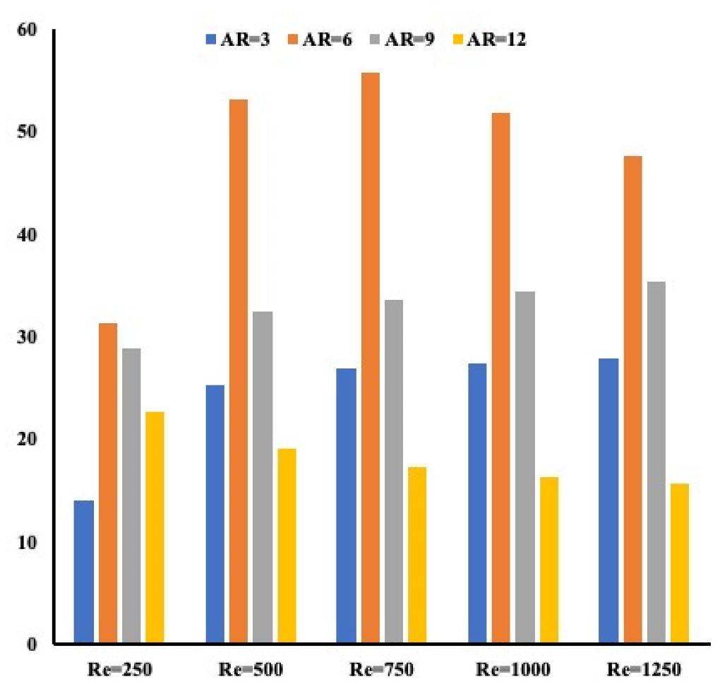
An increase in Reynolds number leads to an increase in the pressure drop is evident from this correlation. If one combines Figure 8 and Figure 9, we can evaluate the performance evaluation criterion. It has been known that this parameter defined in Equation (9) provides the optimum configuration considering the energy and the flow. Figure 11 provides this coefficient for all cases. It is evident that as the aspect ratios increase, heat enhancement represented by the Nusselt number increases, and the friction factor decreases. The reason is that the flow is traveling through the channel for aspect ratio 12 compared to another aspect ratio where the flow travels through the channel and on top of the test section where no wall resistance is found. This leads to a larger pressure drop. One may conclude from Figure 11 that the optimum configuration is with aspect ratio 12 regardless of the flow rate or Reynolds number. This finding is based on a combination of flow behavior and heat removal.
Since the performance evaluation criterion is an important parameter, a correlation has been formed as a function of the aspect ratio and the Reynolds number. Equation (14) shows a relation between PEC and the independent parameters which are the Reynolds number and the height of the channels.
If one ignores the flow effect and evaluates the heat removal solely, Figure 12 presents the energy taken away from the hot plate for all configurations. It appears that the aspect ratio AR = 6 is the configuration for which most of the heat is removed. This finding applied to all Reynolds numbers. The best Reynolds number for such a configuration is when Reynolds number is equal to 750 after which the heat removal decreases further. One may recall the temperature profiles in Figure 6 where it is pointed out that the largest temperature gradient is found for aspect ratio AR = 6. A positive temperature slope is detected at this aspect ratio.
6. Conclusions
In the present study, an effort is focused on investigating the importance of mini-channel height in heat enhancement. The novelty of this present work is to investigate the importance of channel height but more important is the interaction between flow in mini-channel and free flow above the channel. The combination of these two types of flow affected the heat removal. It is found that an aspect ratio of 6, meaning half the channel height, is the best configuration possible. We have also demonstrated that such configuration performs at a Reynolds number of 750 thus a laminar regime.
Author Contributions
Conceptualization, M.Z.S.; methodology, Z.A. and M.Z.S.; software, M.Z.S.; validation, M.Z.S. and Z.A.; formal analysis, M.Z.S.; investigation, M.Z.S.; resources, M.Z.S.; data curation, M.Z.S.; writing—original draft preparation, M.Z.S. and Z.A.; writing—review and editing, M.Z.S. and Z.A.; visualization, M.Z.S. and Z.A.; supervision, M.Z.S.; project administration, M.Z.S.; funding acquisition, M.Z.S. and Z.A. All authors have read and agreed to the published version of the manuscript.
Funding
This research was funded by [National Science and Engineering Research Council Canada, Faculty of Engineering and Architecture, Ryerson University], [Qatar Foundation] grant number [NPRP12S-0123-190011].
Conflicts of Interest
The authors declare no conflict of interest.
References
- Saghir, M.Z.; Mohamad, A.M. Effectiveness in incorporating Brownian and thermophoresis effects in modeling the convective flow of water-Al2O3 nanoparticles. Int. J. Numer. Methods Heat Fluid Flow 2018, 109, 47–63. [Google Scholar] [CrossRef]
- Welsford, C.; Bayomy, A.M.; Saghir, M.Z. Role of metallic foam in heat storage in the presence of Nanofluid and mcroencapsulated phase change material. Therm. Sci. Eng. Prog. 2018, 7, 61–69. [Google Scholar] [CrossRef]
- Bayomy, A.M.; Saghir, M.Z. Thermal performance of finned Aluminum heat sink filled with ERG Aluminum foam: Experimental and numerical approach. Int. J. Energy Res. 2020, 44, 5217. [Google Scholar] [CrossRef]
- Alhajaj, Z.; Bayomy, A.; Saghir, M.Z.; Rahman, M. Flow of nanofluid and hybrid fluid in porous channels: Experimental and numerical approach. Int. J. Thermofluids 2020, 1–2, 100016. [Google Scholar] [CrossRef]
- Welsford, C.A.; Delisle, C.S.; Plant, R.D.; Saghir, M.Z. Effects of nanofluid concentration and channeling on the thermal effectiveness of highly porous open-cell foam metals: A numerical and experimental study. J. Therm. Anal. Calorim. 2019, 140, 1507–1517. [Google Scholar] [CrossRef]
- Delisle, C.S.; Welsford, C.A.; Saghir, M.Z. Forced convection study with microporous channels and nanofluid: Experimental and numerical. J. Therm. Anal. Calorim. 2019, 140, 1205–1214. [Google Scholar] [CrossRef]
- Saghir, M.Z.; Welsford, C.; Thanapathy, P.; Bayomy, A.M.; Delisle, C. Experimental Measurements and Numerical Computation of Nano Heat Transfer Enhancement Inside a Porous Material. J. Therm. Sci. Eng. Appl. 2019, 12. [Google Scholar] [CrossRef]
- Welsford, C.; Thanapathy, P.; Bayomy, A.M.; Ren, M.; Saghir, M.Z. Heat enhancement using aluminum metal foam: Experimental and numerical approach. J. Porous Media 2020, 23, 249–266. [Google Scholar] [CrossRef]
- Plant, R.D.; Hodgson, G.; Impellizzeri, S.; Saghir, M.Z. Experimental and numerical investigation of heat enhancement using a hybrid nanofluid of copper oxide/alumina nanoparticles in water. J. Therm. Anal. Calorim. 2020, 141, 1951–1968. [Google Scholar] [CrossRef]
- Plant, R.D.; Saghir, M.Z. Numerical and experimental investigation of high concentration aqueous alumina nanofluids in a two and three channel heat exchanger. Int. J. Thermofluids 2020, 9, 100055. [Google Scholar] [CrossRef]
- Dominic, A.; Devahdhanush, V.S.; Suresh, S. An experimental investigation on the effect of relative waviness on performance of minichannel heat sinks using water and nanofluids. Heat Mass Transf. 2021, 1–16. [Google Scholar] [CrossRef]
- Feng, Z.; Ai, X.; Wu, P.; Lin, Q.; Huang, Z. Experimental investigation of laminar flow and heat transfer characteristics in square minichannels with twisted tapes. Int. J. Heat Mass Transf. 2020, 158, 119947. [Google Scholar] [CrossRef]
- Ho, C.J.; Chiu, Y.H.; Yan, Y.M.; Ghalambazd, M. Cooling performance of Al2O3-water nanofluid flow in a minichannel with thermal buoyancy and wall conduction effects. Case Stud. Therm. Eng. 2018, 12, 833–842. [Google Scholar] [CrossRef]
- Ho, C.; Chang, P.-C.; Yan, W.-M.; Amani, P. Efficacy of divergent minichannels on cooling performance of heat sinks with water-based MEPCM suspensions. Int. J. Therm. Sci. 2018, 130, 333–346. [Google Scholar] [CrossRef]
- Ho, C.; Liao, J.-C.; Yan, W.-M.; Amani, M. Experimental study of transient thermal characteristics of nanofluid in a minichannel heat sink with MEPCM layer in its ceiling. Int. J. Heat Mass Transf. 2019, 133, 1041–1051. [Google Scholar] [CrossRef]
- Moraveji, M.K.; Ardehali, R.M.; Ijam, A. CFD investigation of nanofluid effects (cooling performance and pressure drop) in mini-channel heat sink. Int. Commun. Heat Mass Transf. 2013, 40, 58–66. [Google Scholar] [CrossRef]
- Ho, C.J.; Chung, Y.; Lai, C.-M. Thermal performance of Al2O3/water nanofluid in a natural circulation loop with a mini-channel heat sink and heat source. Energy Convers. Manag. 2014, 87, 848–858. [Google Scholar] [CrossRef]
- Rimbault, B.; Nguyen, C.T.; Galanis, N. Experimental investigation of CuO–water nanofluid flow and heat transfer inside a microchannel heat sink. Int. J. Therm. Sci. 2014, 84, 275–292. [Google Scholar] [CrossRef]
- Kumar, V.; Sarkar, J. Two-phase numerical simulation of hybrid nanofluid heat transfer in minichannel heat sink and experimental validation. Int. Commun. Heat Mass Transf. 2018, 91, 239–247. [Google Scholar] [CrossRef]
- Arshad, W.; Ali, H.M. Experimental investigation of heat transfer and pressure drop in a straight minichannel heat sink using TiO2 nanofluid. Int. J. Heat Mass Transf. 2017, 110, 248–256. [Google Scholar] [CrossRef]
- Kim, Y.; Kim, M.; Ahn, C.; Kim, H.U.; Kang, S.-W.; Kim, T. Numerical study on heat transfer and pressure drop in laminar-flow multistage mini-channel heat sink. Int. J. Heat Mass Transf. 2017, 108, 1197–1206. [Google Scholar] [CrossRef]
- Sajid, M.U.; Ali, H.M.; Sufyan, A.; Rashid, D.; Zahid, S.U.; Rehman, W.U. Experimental investigation of TiO2–water nanofluid flow and heat transfer inside wavy mini-channel heat sinks. J. Therm. Anal. Calorim. 2019, 137, 1279–1294. [Google Scholar] [CrossRef]
- Dominic, A.; Sarangan, J.; Suresh, S.; Devahdhanush, V.S. An experimental study of heat transfer and pressure drop characteristics of divergent wavy minichannels using nanofluids. Heat Mass Transf. 2016, 53, 959–971. [Google Scholar] [CrossRef]
- Plant, R.D.; Hodgson, G.K.; Impellizzeri, S.; Saghir, M.Z. Experimental investigation of heat transfer with various aqueous mono/hybrid Nanofluids in a Multi-channel heat exchanger. Processes 2021. submitted. [Google Scholar]
- Saghir, M.Z.; Bayomy, A.M.; Abdul Rahman, M.D. Heat enhancement effectiveness using multiple twisted tape in rectangular channels. Fluids 2021, 6, 188. [Google Scholar] [CrossRef]
Figure 1.
Experimental setup.

Figure 2.
Geometrical model with different inserts. (a) Experimental setup; (b) Insert mini channels.
Figure 2.
Geometrical model with different inserts. (a) Experimental setup; (b) Insert mini channels.
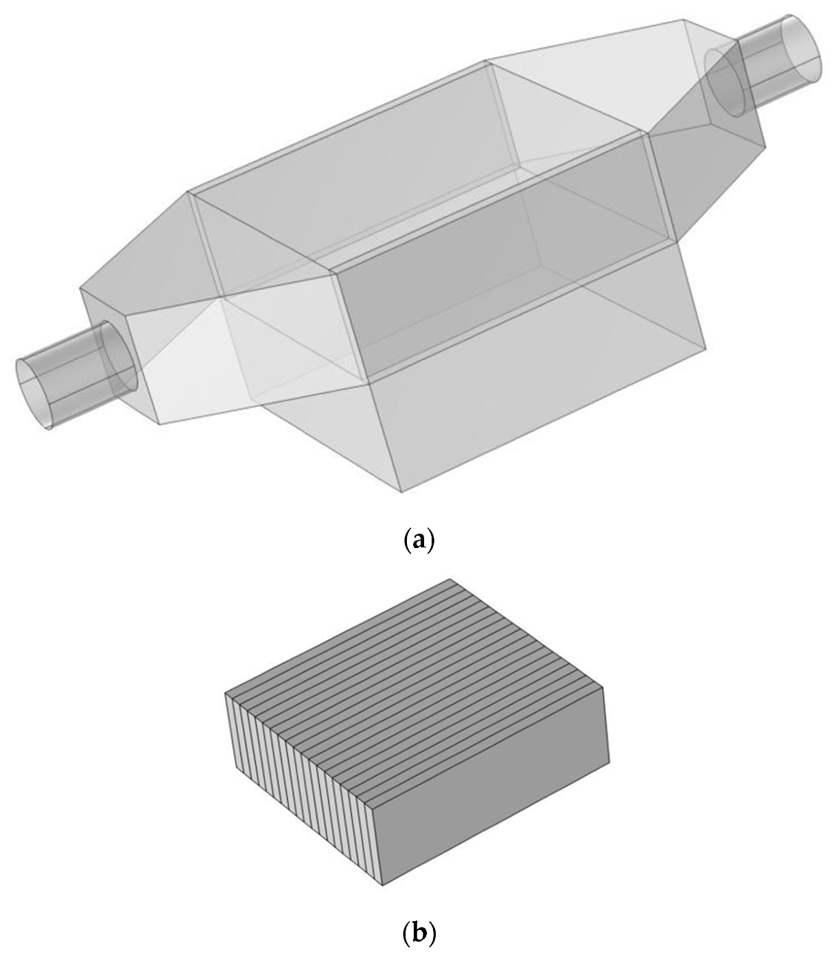
Figure 3.
Mesh sensitivity analysis.
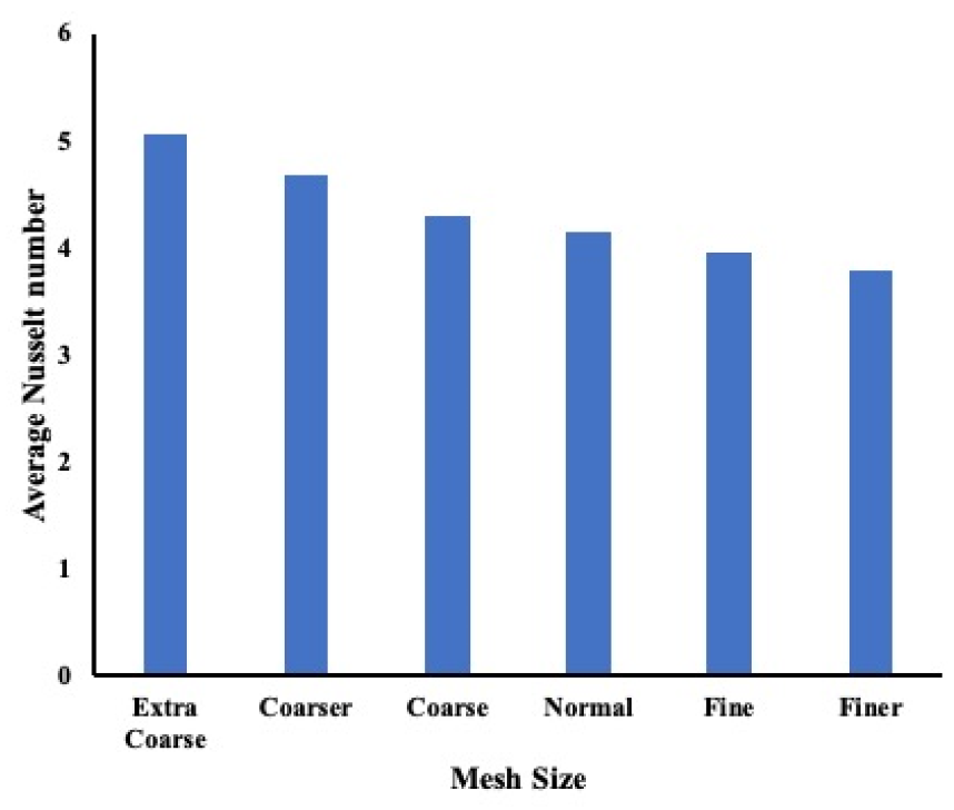
Figure 4.
Comparison with experimental data for three-channel configurations. (a) Temperature variation along with the flow; (b) Local Nusselt number along with the flow.
Figure 4.
Comparison with experimental data for three-channel configurations. (a) Temperature variation along with the flow; (b) Local Nusselt number along with the flow.

Figure 5.
Temperature and local Nusselt number variation in mini-channel configuration (AR = 6). (a) Temperature distribution. (b) Local Nusselt number variation.
Figure 5.
Temperature and local Nusselt number variation in mini-channel configuration (AR = 6). (a) Temperature distribution. (b) Local Nusselt number variation.

Figure 6.
Flow distribution at the middle of the test section (a–d) and near the wall (e–h).
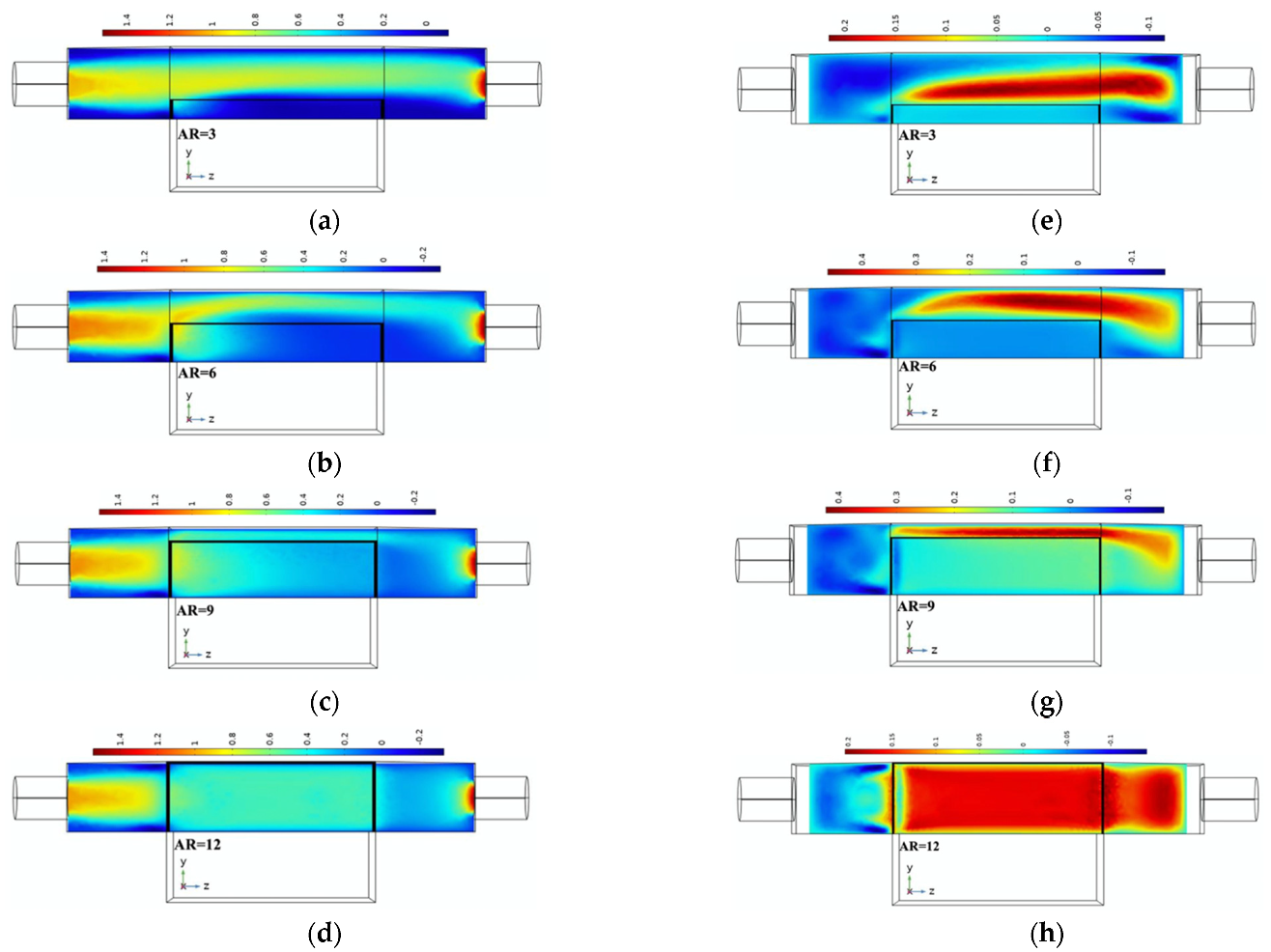
Figure 7.
Temperature distribution at the middle of the test section (a–d) and near the wall (e–h).
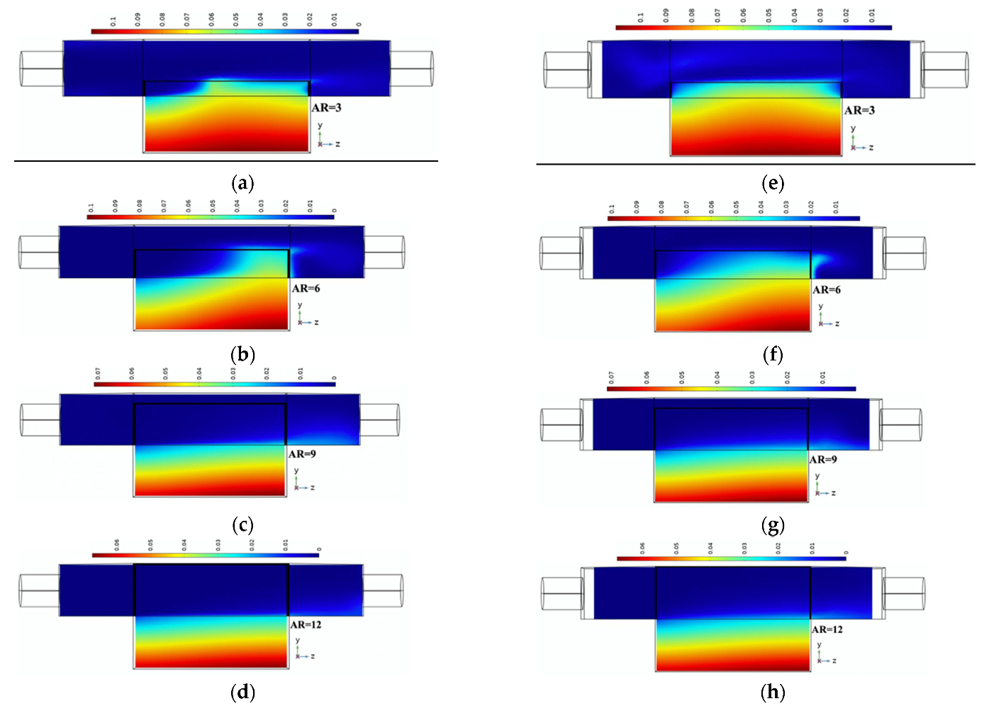
Figure 8.
Average Nusselt number for all cases.

Figure 9.
Friction factor for all cases.
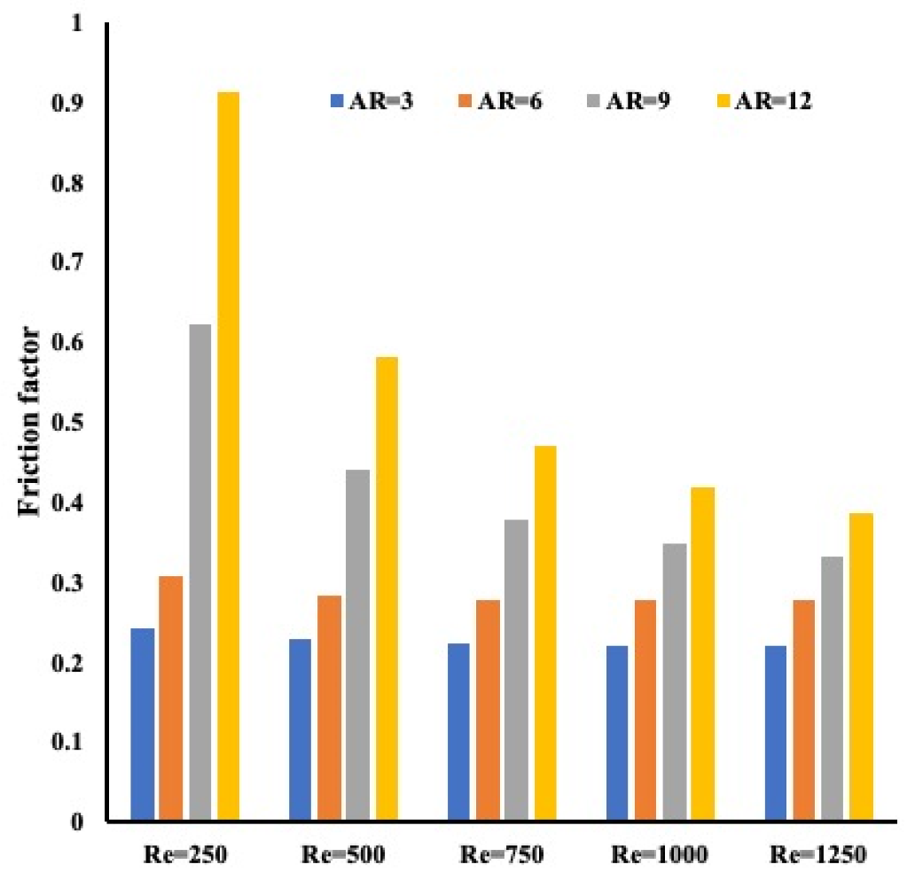
Figure 10.
Pressure drop variation for all cases.

Figure 11.
Performance coefficient for all cases.

Figure 12.
Heat removal for all cases.

Table 1.
Water physical properties.
| Fluids | (kg/m/s) | (kg/m3) | cp(J/kg/K) | k(W/m/K) |
|---|---|---|---|---|
| Water | 0.001002 | 998.2 | 4182 | 0.613 |
Table 2.
Mesh information for a different level of meshing.
| Extra coarse mesh | 17,888 total number of elements |
| Coarser mesh | 30,763 total number of elements |
| Coarse mesh | 68,890 total number of elements |
| Normal mesh | 112,088 total number of elements |
| Fine mesh | 321,591 total number of elements |
| Finer mesh | 919,451 total number of elements |
Publisher’s Note: MDPI stays neutral with regard to jurisdictional claims in published maps and institutional affiliations. |
© 2021 by the authors. Licensee MDPI, Basel, Switzerland. This article is an open access article distributed under the terms and conditions of the Creative Commons Attribution (CC BY) license (https://creativecommons.org/licenses/by/4.0/).
Share and Cite
MDPI and ACS Style
Saghir, M.Z.; Alhajaj, Z. Optimum Multi-Mini-Channels Height for Heat Enhancement under Forced Convection Condition. Energies 2021, 14, 7020. https://doi.org/10.3390/en14217020
AMA Style
Saghir MZ, Alhajaj Z. Optimum Multi-Mini-Channels Height for Heat Enhancement under Forced Convection Condition. Energies. 2021; 14(21):7020. https://doi.org/10.3390/en14217020
Chicago/Turabian StyleSaghir, M. Z., and Z. Alhajaj. 2021. "Optimum Multi-Mini-Channels Height for Heat Enhancement under Forced Convection Condition" Energies 14, no. 21: 7020. https://doi.org/10.3390/en14217020
Note that from the first issue of 2016, this journal uses article numbers instead of page numbers. See further details here.