
Investigation of Control Characteristics for a Molten Salt Reactor Plant under Normal and Accident Conditions


1
School of Resource & Environment and Safety Engineering, University of South China, Hengyang 421001, China
2
Chair of Nuclear Technology, Department of Mechanical Engineering, Technical University of Munich, 85748 Garching, Germany
*
Author to whom correspondence should be addressed.
Energies 2021, 14(17), 5279; https://doi.org/10.3390/en14175279
Submission received: 2 August 2021
/
Revised: 13 August 2021
/
Accepted: 20 August 2021
/
Published: 25 August 2021
(This article belongs to the Special Issue Advances in Fluid Power Systems)
Abstract
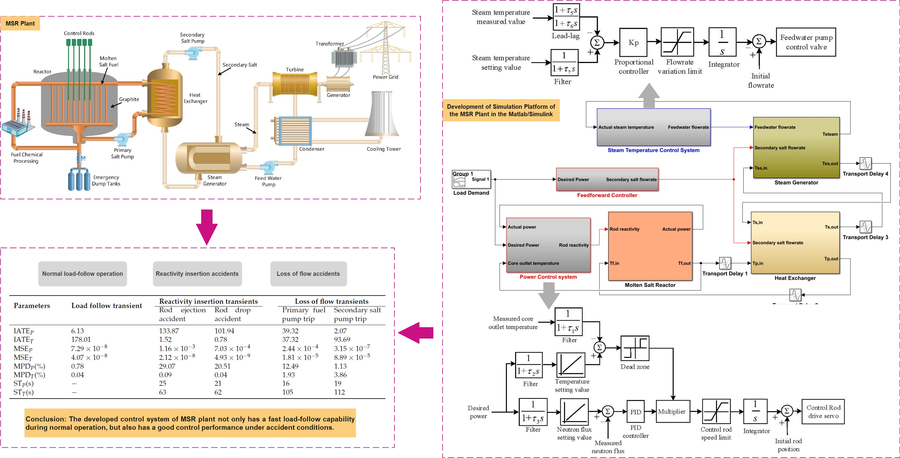
:A molten salt reactor (MSR) has unique safety and economic advantages due to the liquid fluoride salt adopted as the reactor fuel and heat carrier fluid. The operation scheme and control strategy of the MSR plant are significantly different from those of traditional solid-fuel reactors because of the delayed neutron precursors drift with the liquid-fuel flow. In this paper, a simulation platform of the MSR plant is developed to study the control characteristics under normal and accident conditions. A nonlinear dynamic model of the whole system is built in the platform consisting of a liquid-fuel reactor with a graphite moderator, an intermediate heat exchanger and a steam generator. A new control strategy is presented based on a feed-forward and feedback combined scheme, a power control system and a steam temperature control system are designed to regulate load changes of the plant. Three different types of operation conditions are simulated with the control systems, including transients of normal load-follow operation, a reactivity insertion accident and a loss of flow accident. The simulation results show that the developed control system not only has a fast load-follow capability during normal operation, but also has a good control performance under accident conditions.

1. Introduction
The initial concept design of the molten salt reactor (MSR) was developed by the Oak Ridge National Laboratory (ORNL) for the purpose of driving a nuclear powered aircraft, which adopted liquid uranium fluoride as both reactor fuel and coolant [1]. A test loop of the aircraft reactor was developed to explore the preliminary feasibility of molten fluoride fuel at ORNL [2]. By the 1960s, the eighth MW Molten Salt Reactor Experiment (MSRE) was built and underwent critical operation. Based on the experience with the MSRE’s technology, more conceptual designs of MSRs were presented, with single-fluid and two-fluid circuits, thermal-spectrum and fast-spectrum reactors [3,4]. Due to high melting point and high viscosity of the fuel salt, its long-term operation may cause irradiation and corrosion of structural materials. Another difficulty is that the liquid fuel flowing from the reactor core needs to be purified quickly, which poses a challenge to the chemical treatment of nuclear fuel [5]. However, the on-line fuel supply and reprocessing systems of the MSR bring a low excess reactivity to the reactor, in which the liquid fuel is separated from the fission products and the highly radioactive waste can be removed from the primary loop. In particular, the overheated nuclear fuel can be automatically discharged into the safety storage tanks under severe accident conditions [5]. The boiling point of the fuel salt is high and the operating pressure of the reactor vessel is close to atmospheric pressure. Furthermore, the fluoride fuel has a higher heat capacity than the traditional reactor coolant, which means that the molten liquid fuel could enhance core power density and make the reactor system more compact [6]. Because of its great safety and economic advantages compared with solid-fuel reactors, the MSR was chosen as one of the six reactor types by the international forum of Generation IV nuclear energy systems [7].
In recent years, there has been a rapid development of the design, simulation and operation of the MSR all over the world. A high-temperature coated particle fuel with a salt-coolant reactor (FHRs) was presented by US researchers, both preliminary conceptual design of the reactor core, and an experimental test facility of liquid fluoride-salt were completed [8,9]. In Europe, the EURATOM framework programs were carried out to develop two fast-spectrum MSR concepts for fuel breeding and nuclear waste burning, including a Molten Salt Actinide Recycler and Transmuter (MOSART) and a Molten Salt Fast Reactor (MSFR) [10,11]. The SPHINX project in the Czech Republic was performed for the technologies of thorium–uranium fuel cycle, in which the reactor physics and fuel chemistry, on-line reprocessing technology, and structural material were studied by theoretical and experimental methods [12]. Huke et al. [13] proposed a Dual Fluid Reactor (DFR) at the Institute for Solid-State Nuclear Physics (IFK), which adopts two-fluid molten salt fuel and liquid lead coolant in the core. The reactor neutronics/thermal-hydraulics of the DFR was simulated and analyzed in [14,15], and Liu et al. [16] presented a Small Modular Dual Fluid Reactor (SMDFR) based on the DFR concept. A combined MSR system was designed by Furukawa et al. [17] in Japan, in which the power is generated by molten-salt reactors (FUJI) and the nuclide 233U is produced by a spallation reaction in Accelerator Molten-Salt Breeders (AMSB). A Thorium Molten Salt Reactor (TMSR) project was implemented by the Chinese Academy of Sciences for the utilization of thorium resources and hydrogen production [18]. For the developed MSR concepts worldwide, the safety operation and stable control of the reactors play a key role in their technology roadmap and engineering implementation.
The dynamic characteristics and control strategy of the MSR are significantly different from those of traditional solid-fuel reactors because of delayed neutron drift caused by the liquid-fuel flow in the primary loop. Therefore, it is necessary to develop a real-time and accurate dynamic model for the control system design and simulation of the MSR. Simplified dynamic models and control systems for MSR concepts have been developed by several researchers. Sides Jr. [19] carried out a preliminary investigation of the dynamics and control for a single-fluid Molten-Salt Breeder Reactor (MSBR) based on a lumped-parameter system model. Tripodo et al. [20] developed a control-oriented power plant simulator for the molten salt fast reactor, in which a one-dimensional flow model of a liquid fuel with a neutron point-kinetics model was built for the reactor taking into account the drift of the delayed neutron precursors along the fuel circuit and the consequent reactivity insertion. A point reactor kinetics model and heat transfer nodal model of the MSBR core were built for the controller design of the fuel temperature [21]. A non-linear dynamic model of the MSR core was developed by Zarei [22] and a power control scheme with the classic PID controller has also been proposed. Zeng et al. [23] presented a fuzzy-PID composite control approach based on a linear model of the MSBR core, and the Internal Model Control (IMC) method was used for the improvement of the PID controller performance for the reactor power control [24]. However, these simplified lumped parameter models, especially the linearized models, could not describe the real-time spatial distribution of the reactor parameters during transient operation, thereby affecting the control performance and regulation precision of the designed controller. These studies mainly focused on the power control of the MSR core without a simulation platform of the whole-plant system; thus, the control system could not reflect the coupling effects between the various subsystems in the actual operation of the plant. In addition, the designs of these controllers do not take into account the input saturation and dead zone of the control mechanism, which are necessary for its engineering realization.
The objective of this study is to develop a simulation platform of the entire system to study the control characteristics of the MSR plant under normal and accident conditions. The 2250 MW MSR concept presented by Robertson [25] was chosen as the reference configuration for the system modeling and controller design. A non-linear distributed parameter model of the whole system was built in the platform consisting of a liquid-fuel reactor with a graphite moderator, an intermediate heat exchanger and a steam generator. A new control strategy is presented based on a feed-forward and feedback combined scheme, in which the reactor power control system and steam temperature control system, considering the input saturation and dead zone, are designed to adjust load changes of the plant. In order to investigate the operation and control characteristics of the MSR plant, three different transients have been simulated with the new simulation platform, which include normal load-follow operation, reactivity insertion accident and loss of flow accident.
2. MSR Plant Description
A conceptual design of 2250 MW MSR plant was presented by ORNL, in which a liquid salt of Uranium and Thorium (U–Th) fluoride was adopted as the reactor fuel and heat carrier fluid [25]. This thermal-spectrum reactor concept was chosen as the reference configuration to study the transient operation and control characteristics of the MSR plant in this work. The flow diagram of the whole system is shown in Figure 1.
The MSR plant was composed of a thermal-spectrum molten salt reactor with graphite moderator, 4 tubular heat exchangers (IHX) and 16 steam generators (SG). The reactor core was divided into two zones: a central zone and an outer zone. The mass flow rate fractions of the primary fuel salt in the central zone and outer zone were 81.4% and 18.6%, respectively, which were determined by the heat generation rate in each zone to keep the temperature rise equal. The on-line fuel processing system resulted in a low excess reactivity in the reactor, in which the fission products and the minor actinides could be separated from the liquid fuel salt in the primary loop. In particular, under severe accident conditions, the overheated nuclear fuel would be automatically discharged into the emergency dump tanks so that the reactor could be shut down safely. The control rod could move up and down in the reactor core through the drive mechanism to introduce reactivity in order to adjust the core power. The primary fuel salt flowed upward from the bottom of the core through the graphite-moderated region, and then entered the tube side of heat exchangers. The design point temperature of the fuel salt entering the core was 838.7 K and that at the core outlet was 977.6 K. The fission energy generated by the reactor core was transferred from the primary fuel salt of the tube side to the counter-current secondary salt of the shell side in the heat exchangers. The cold-leg temperature of the secondary salt at the design point was 727.6 K, and the hot-leg temperature was 894.3 K. The temperature of secondary salt could be regulated by changing the pump speed under various operating power points. This salt flowed in each heat exchanger to form a closed secondary loop, and each loop supplied heat to four steam generators. Thus, there was a total of 16 steam generators in the plant. The high-temperature secondary salt flowed into the shell side of horizontal supercritical steam generators to heat the feedwater, in which the pressure of water/steam was close to 25 MPa in the tube side of steam generators. The feedwater entered the U-tube of steam generators and became superheated steam after being heated by the secondary salt, and finally flowed into the turbine to generate electricity. The feedwater pump was used to adjust the flow rate to keep the outlet temperature of the steam at the design value of 810.9 K under steady-state conditions and maintain fluctuations as small as possible during transient operations, thereby providing a stable steam quality to the turbine. The pressure in the SG-tube side and the inlet temperature of the feedwater were also held constant during transient operations. The main design parameters used in this work are summarized in Table 1.
3. Development of the MSR Plant Simulation Platform
In this section, the nonlinear distributed parameter model of the whole system, the reactor power control system and the steam temperature control system for the MSR plant developed in the simulation platform are described.
3.1. Whole System Nonlinear Model
In order to avoid the simplifications and approximations introduced in the process of model linearization, this paper directly solves the nonlinear and time-varying system model of the MSR plant, which can more accurately reflect the dynamic behavior and the coupling effects between the various subsystems in the actual operation of the plant. The nonlinear distributed parameter model consists of a molten salt reactor model, a heat exchanger model and a steam generator model. A schematic diagram of the model node division is shown in Figure 2. In order to obtain the temperature distribution of the liquid fuel and the graphite, the core is divided into N nodes in the axial direction and two zones in the radial direction. The heat transfer coefficient of the primary fuel salt and secondary salt in the nonlinear model change with the mass flow rate and the salt temperatures. The molten salt fuel, tube wall and secondary salt in the heat exchanger are also divided into N nodes in the axial direction, and the node division of the steam generator is determined in a similar manner. In the process of numerical calculation, the spatial term of the differential equations of the whole system is first discretized, and then, the time-dependent term of the differential equations is calculated by a backward differentiation formulas (BDFs) method [26].
3.1.1. Molten Salt Reactor
The neutron kinetics model of the reactor is built by using the point-reactor kinetics equations with the drift of delayed neutron precursors and temperature reactivity feedbacks of the liquid fuel and the graphite. The equations are as follows:
where N is the neutron density, t is the time, is the total delayed neutron fraction, is the delayed neutron fraction of group j, is the neutron generation time, and are the delayed neutron precursor concentration and decay constant of group j, respectively, denotes the transit time of liquid fuel through the core, denotes the transit time of liquid fuel through the external loop. The values of the transit time ( and ) are presented in Table 1 [27]. Taking into account temperature reactivity feedbacks of the fuel and the graphite and the reactivity variation introduced by the control rod, the reactivity model could be written as:
where and are temperature reactivity coefficients of the molten salt fuel and the graphite, respectively, and are the average temperatures of the fuel and the graphite in the core, respectively, denotes the reactivity variation of the control rod movement. Calculating Equations (1) and (2) in steady state, the initial reactivity could be derived by the following formula:
The magnitude of the total thermal power is proportional to the neutron density in Equation (1), and the axial distribution of the power in the core is approximately a cosine distribution with a 2.4 m extrapolation distance [28]. The fraction of energy generated in the liquid fuel and in the graphite moderator are 91.9% and 8.1%, respectively.
The energy released by the fission reactions in the core is removed by the flowing molten-salt fuel. In order to obtain the spatial distribution of temperatures in the fuel and in the graphite, the core is divided into N nodes in the axial direction and two zones in the radial direction, as shown in Figure 2. According to the conservation principle of mass and energy, the heat transfer equation for the molten salt fuel in the central zone is as follows:
where , and are the mass, specific heat and temperature of the fuel in the axial node i, respectively, denotes the mass flow rate in the central zone, is the heat transfer coefficient between the fuel and the graphite, is the heat transfer area of node i, is the fraction of fission heat generated in fuel node i, is the total thermal power of the reactor.
For the graphite, the heat transfer equation is described as:
where , and are the mass, specific heat and temperature of the graphite in the axial node i, respectively, is the fraction of heat generation in graphite node i.
The heat transfer equations of the fuel and the graphite in the outer zone is derived in the same way. The molten salt fuel from the two zones of the core is mixed in the reactor upper plenum, the outlet temperature is given by:
where is the fraction of mass flow rate of the fuel in the central zone, and are the fuel temperatures at the node N of the central zone and the outer zone, respectively.
3.1.2. Heat Exchanger
The heat exchanger adopts a shell-and-tube structure in which the primary fuel salt flows downwards in the tube side and the secondary salt flows upwards in the shell side. The node divisions of primary fuel salt, tube wall and secondary salt in the heat exchanger are shown in Figure 2. The heat transfer model of the primary fuel salt is as follows:
where , and are the mass, specific heat and temperature of the primary fuel salt in the axial node i respectively, denotes the mass flow rate in the tube side, is the heat transfer coefficient between the primary fuel salt and the tube wall, is the heat transfer area of node i.
For the tube wall:
where , and are the mass, specific heat and temperature of the tube wall in the axial node i, respectively.
For the secondary salt:
where , and are the mass, specific heat and temperature of the secondary salt in the axial node i, respectively, denotes the mass flow rate in the shell side, is the heat transfer coefficient between the secondary salt and the tube wall, is the heat transfer area of node i.
3.1.3. Steam Generator
The steam generator is a U-tube counter-current exchanger, with the high-temperature secondary salt flowing into the shell side and the feedwater entering the U-tube side, which becomes overheated steam after being heated by the secondary salt. The heat transfer model of the secondary salt is written as:
where , and are the mass, specific heat and temperature of the secondary salt in the axial node i of steam generators, respectively, denotes the mass flow rate in the shell side, and denote the heat transfer coefficient and the heat transfer area between the secondary salt and the U-tube wall.
For the U-tube wall:
where , and are the mass, specific heat and temperature of the U-tube wall in the axial node i, respectively.
The water and steam are in a supercritical state due to their high temperature and pressure in the U-tube of the steam generator. Thus, the water/steam mixture is a single-phase fluid, and the heat transfer model of the water/steam could be described as:
where , and are the mass, specific heat and temperature of the water/steam in the axial node i, respectively, denotes the mass flow rate in the tube side, is the heat transfer coefficient between the water/steam and the tube wall, is the heat transfer area of node i.
The thermophysical properties of materials in Equations (5)–(13) were inserted into the thermal-hydraulic model based on the experimental data and empirical correlation in the design report [25], which are presented in Table 2. The relation of heat transfer coefficients to mass flow rate is shown in Figure 3 obtained from the empirical formula in the literature [28].
3.1.4. Transport Delays between Various Subsystems
Taking into account the transit time of the fluid flow in the pipes connecting the various subsystems, transport delay equations of the primary fuel salt between the reactor core and the heat exchanger are used in the dynamic simulation platform of the MSR plant:
where and are the inlet and outlet temperatures of the primary fuel salt in the core, respectively, and are the inlet and outlet temperatures of the primary fuel salt in the heat exchanger, respectively, the values of delay times and are 2 s and 2.3 s, respectively.
For the secondary-salt loop, the transport delays in the hot and cold legs can be written as:
where and are the secondary-salt temperatures in the heat exchanger and the steam generator, respectively, the values of delay times and are 14.5 s and 11.9 s, respectively [28].
3.2. Plant Control System
Before designing the control system, the operation parameters should be obtained by a series of steady state calculations at different plant loads. Figure 4 shows the results for the temperature as a function of the plant load. To protect the turbine blades, the steam outlet temperature remains constant at 810.9 K. Thermal cycle efficiency and control (such as turbine model, condenser model, etc.) are not discussed in this work; thus, a simplified assumption is adopted that the feedwater temperature maintains a constant value of 644.3 K during different operation transients. The variation of the core outlet temperature is a linear function of the load demand. The reactor inlet temperature remains constant when the load is below 50% full power (FP) and linearly changes from 810.9 K to 838.7 K for loads above 50% FP. The cold-leg and hot-leg temperatures of the secondary salt are determined by the steady-state heat balance points, in which the minimum operation temperature is higher than its melting point.
A new control strategy was proposed to realize the desired operation conditions, which mainly includes two control modules for load tracking: the power control system and the steam temperature control system. The objective of the power control system in this work is to make the total thermal power follow the variation of the load demand as quickly as possible. The steam temperature control system is designed to keep the outlet temperature of the steam at the design value of 810.9 K under steady-state conditions and maintain the fluctuations as small as possible during transient operations, thereby providing a stable steam quality to the turbine. A schematic diagram of the plant control system is shown in Figure 5. The measured values of neutron flux and reactor outlet temperature are compared with those of set-values for the plant load demand. The deviations of neutron flux and outlet temperature ( and ) are fed back to the control rod servo for suitable reactivity adjustments. In order to avoid neutronic fluctuations due to the drift of the delayed neutron precursors, the drift times ( and ) are kept constant during transient operations, which means the mass flow of the primary pump is always maintained at the 100% FP value. At the same time, a feed-forward control scheme is adopted to match the secondary salt temperature to its set-point by regulating the secondary pump, in which the feed-forward tuning parameter of the pump is programmed as a function of the load demand. The steam temperature control system is designed to adjust the mass flow rate of the feedwater pump when the measured steam outlet temperature deviates from its set-point.
3.2.1. Reactor Power Control System
The reactor power control system is a three input and single output nonlinear controller, the block diagram of the control principle is shown in Figure 6.
According to the demand of the electric grid load, the desired power could be determined and converted to the set-value of the neutron flux. The deviation signal between this set-value and the measured value is sent to the PID controller. After the error signal is processed by the PID controller, the adjustment signal is transmitted to the rod speed controller for calculating the rod movement speed and direction. When we are designing a PID controller for a given system, we follow the steps shown below to obtain a desired response. The first step is to obtain an open-loop response and determine what needs to be improved. The second step is to add a proportional control parameter () to improve the rise time. The third step is to add a derivative control parameter () to reduce the overshoot, and then add an integral control () to reduce the steady-state error. Finally, adjust each of the gains , and until we obtain a desired overall response. The designed values of PID parameters are 0.025, 0.0079 and 0.0028, respectively. Considering the criticality safety of the reactor and the engineering feasibility of the control rod mechanism, the change rate of the controlled reactivity is limited to ±10 pcm/s. In addition, the power control system includes a dead zone block of outlet temperature to avoid frequent actions of the control mechanism caused by signal noise and by extremely small deviations. When the error of the measured outlet temperature and its set-value is below the threshold in the dead zone, a lock signal will be sent to the control rod mechanism to prevent unnecessary actions of the rod drive mechanism in order to extend its service life.
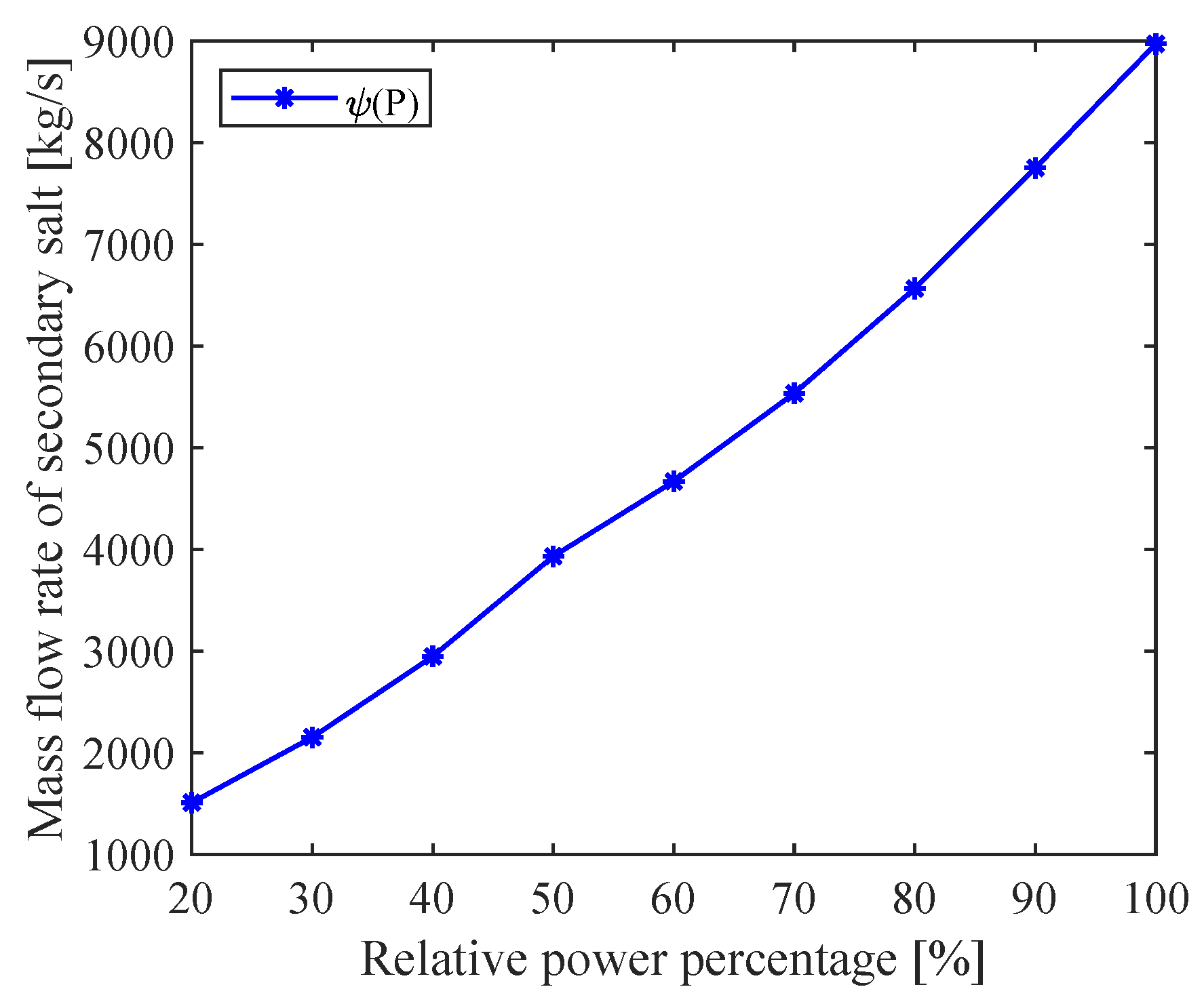
The feed-forward controller is designed to match the secondary salt temperature to its set-point, in which the tuning parameter of the secondary pump is programmed as a function of the load demand. The block diagram of the controller is shown in Figure 7. The mass flow rate of the secondary salt is a nonlinear fitting function based on solutions of the steady state equations for the entire system at different power levels, as shown in Figure 8.
3.2.2. Steam Temperature Control System
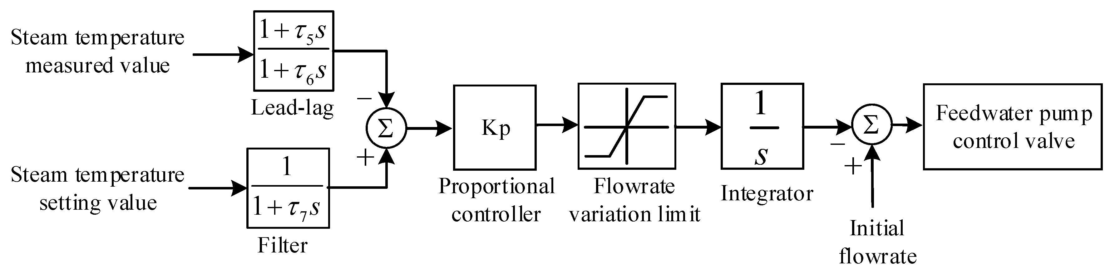
In the process of the plant load variation, the steam temperature deviates from its set value due to the energy imbalance between the various subsystems, thereby generating a temperature error signal. After the deviation signal is processed by the proportional controller, it is transmitted to a limiter of the feedwater flow rate to avoid the temperature oscillation caused by the sharp changes of the pump valve position. The value of is 0.006 and the change rate of the mass flow rate is limited to ±0.5%/s. Meanwhile, the feedback signal of steam temperature will produce a hysteresis effect due to the system thermal inertia. Thus, a lead-lag controller is designed to compensate for the thermal inertia which could improve the response speed of the steam temperature control. The parameter values of the lead-lag controller and are 20 and 1, respectively. The final output signal is sent to the flow-control valve for the adjustment of the feedwater flow rate to keep the steam outlet temperature constant, as shown in Figure 9.
3.3. Implementation of the Plant Nonlinear Model and Control System
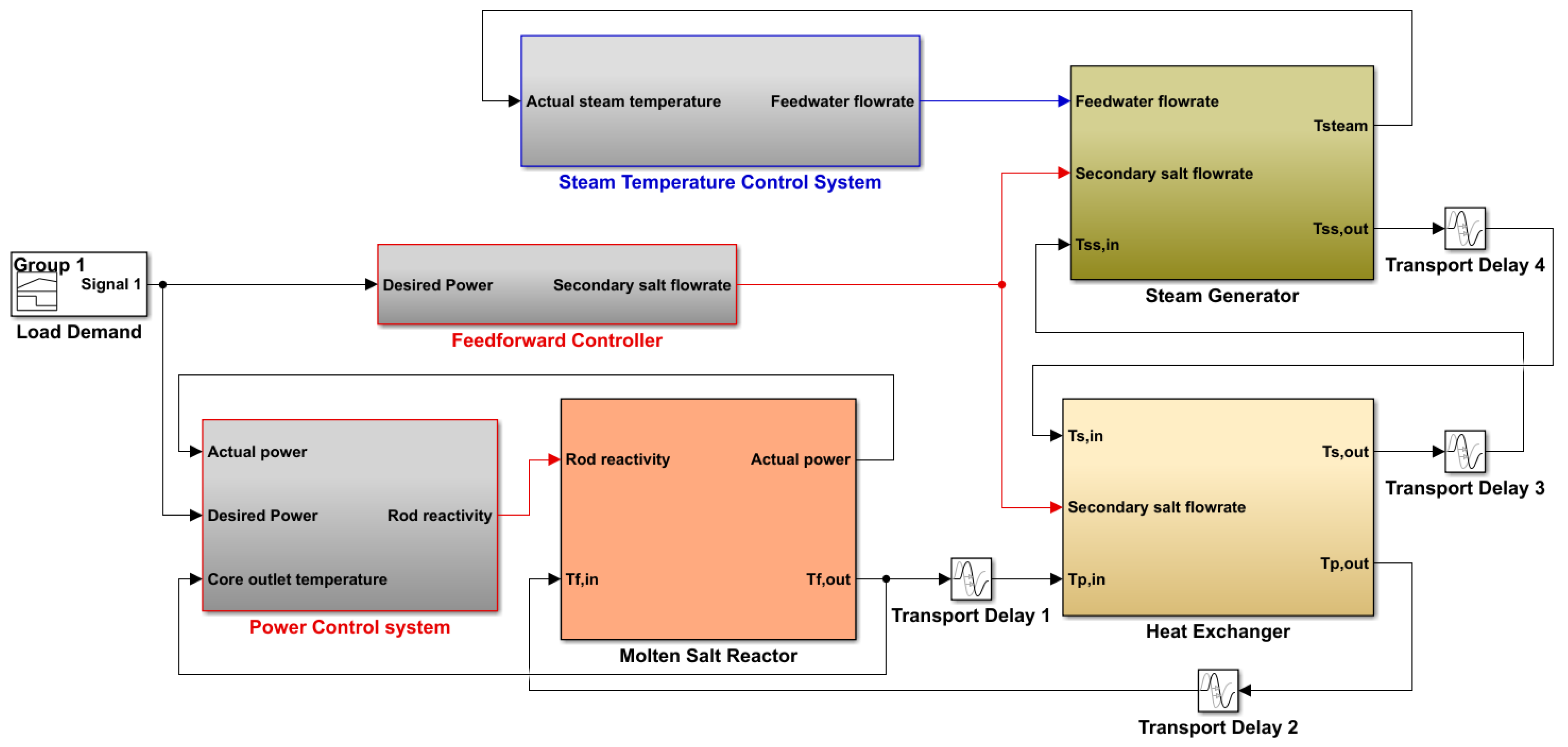
The Matlab/Simulink program has been widely applied to the field of system transient simulation and controller design due to its powerful capabilities for model calculation and numerous toolboxes for simulation analysis. The nonlinear distributed parameter model, the reactor power control system and the steam temperature control system for the MSR plant were developed in the Matlab/Simulink environment. The developed simulation platform is presented in Figure 10, which mainly consists of five parts: the molten salt reactor system, the heat exchanger system, the steam generator system, the power control system, and the steam temperature control system. Based on the developed platform, the nonlinear dynamic model of the whole system could be applied under different transient conditions. With the designed reactor power and steam temperature controllers, the feed-forward and feedback combined control strategy can realize the load tracking of the MSR plant under normal and accident conditions.
4. Results and Discussions
Based on the established dynamic model of the whole system, the reactor power control system and the steam temperature control system were designed in the simulation platform. Three different transients were simulated to investigate the operation and control characteristics of the MSR plant, namely normal load-follow operation, a reactivity insertion accident and a loss-of-flow accident. The following four criteria are often used to quantitatively assess the performance of control systems under different operating conditions [29]:
(i) Integral time absolute error (ITAE) is defined as:
where is the error between the measured value of the controlled variable and its desired value;
(ii) Mean square error (MSE) is defined as:
(iii) Maximum percentage deviation (MPD) is defined as:
where and denote the measured value and the desired value of the controlled variable, respectively;
(iv) Settling time (ST) is the total time required for the response curve to reach and stay within a small range of the final value.
4.1. Load-Follow Operation
A linear load change transient is investigated to test the load-follow capability of the control system, in which the load demand decreases from 100% FP to 40% FP at a speed of 10% FP/min after the steady-state operation for 100 s, and then, the load demand returns to 100% FP at the same rate after equilibrium has been established at 40% FP. The transient responses of the system parameters are presented in Figure 11.
The load demand signal is transmitted into the power control system, as shown in Figure 5. The error signals between the desired values and the measured values of the neutron flux and the fuel outlet temperature ( and ) drive the control rod movement into the core to adjust the reactor power. As shown in Figure 11a,g, the reactivity insertion of the control rod makes the actual power quickly follow the desired power. The actual operating value of the reactor power is almost consistent with the load demand, and the maximum relative deviation does not exceed 1%, as presented in Table 3. Meanwhile, the mass flow rate of the secondary salt serves as a feed-forward tuning parameter which is programmed as a function of the demand load, as shown in Figure 11h. The reactor outlet temperature decreases with the reduction of the reactor power, and the reactor inlet temperature gradually decreases after a slight increase because less heat is transferred into the secondary salt with the reduction of its flow rate in the heat exchanger, as shown in Figure 11c,d.
The load demand signal is also sent to the steam temperature control system to adjust the feedwater flow rate, as shown in Figure 11b,h. With the rapid decrease of reactor power, the heat transferred to the steam generator reduces rapidly, so that the steam temperature drops. Then, the actual value of the steam temperature is compared with its desired value, and the error signal transmitted into the feedwater pump to reduce the mass flow rate in the steam generator. It can be seen from Figure 11b,h that the steam temperature decreases slightly with the drop of reactor power and then increases gradually with the reduction of the feedwater flow rate before reaching a steady-state point around its desired value, and the range of steam temperature variation does not exceed 1 K during the transient. The cold-leg temperature of the secondary salt decreases with the reduction of the reactor power, and the hot-leg temperature of the secondary salt gradually decreases after a small rise with the rapid reduction of the secondary salt flow rate, as shown in Figure 11e,f.
Based on this control scheme, the 40% load condition is followed quickly for this transient and the system parameters stabilize quickly at a new steady-state point. The reactor power and the steam temperature are well controlled during the process of the load increase from 40% FP to 100% FP, as shown in Table 3, where the subscript of the performance parameters represents the reactor power and represents the steam outlet temperature. The simulation results show that the designed control system for the MSR plant has a good load-follow capability, which can quickly adjust the reactor power and the steam temperature with satisfactory accuracy.
4.2. Reactivity Insertion Accident
During the operation of a nuclear power plant, due to the failure of mechanical devices or the actions of the operators, partially inserted shutdown rods can accidentally eject from the reactor or fall into the reactor, and then, positive or negative reactivity is introduced, causing the reactor power to deviate from normal operating conditions. In this work, accident transients caused by both rod ejection (60 pcm positive reactivity) and rod drop (60 pcm negative reactivity) are investigated to test the control system performance.
4.2.1. Rod Ejection Accident
Figure 12 shows the comparative results of the rod ejection transient with and without the plant control system. A step of positive reactivity of 60 pcm is suddenly introduced into the reactor at 50 s, and the load demand maintained at 100% FP level. The transient responses of the system parameters with the control system are compared with those of the case that the control system is inactive under the rod ejection accident.
For the controlled case, the reactor power rapidly increases by 29% when the step positive reactivity of 60 pcm is suddenly introduced into the reactor at 50 s, as shown in Figure 12a. The sudden rise of the reactor power leads to the reactor outlet temperature to increase rapidly from its initial steady-state value. The other temperature parameters also ascend with the increase of the reactor power. Because the load demand signal is kept at l00% FP level, the steam outlet temperature set-point is maintained at 810.9 K. Thus, the load deviation signal is sent to the power control system, and the control rod begins to insert negative reactivity into the reactor to reduce the power until it returns to the l00% FP level. The mass flow rate of the secondary pump is constant since the load demand remains 100% FP. At the same time, the increasing reactor temperature causes an increase of the steam temperature, which is delayed due to the transit time of the heat between different subsystems. The error signal of the steam temperature is transmitted to the control system to adjust the feedwater flow rate. It can be seen from Figure 12b that the steam outlet temperature quickly reaches the steady-state point around its desired value. The performance parameters of the control system during this transient are summarized in Table 3. The simulation results show that the developed control system could effectively deal with the rod ejection accident, thereby maintaining the stable operation of the MSR plant.
For the uncontrolled case, it can be seen from Figure 12 that the power increases by about 51% after 60 pcm positive reactivity is introduced into the reactor, and then, the power decreases gradually due to the negative reactivity introduced by the fuel Doppler feedback effect and the graphite temperature feedback effect, and finally reaches a new equilibrium value of 135% FP. Meanwhile, the temperatures of the primary fuel, the secondary salt and the steam also ascend with the power increase and then gradually stabilize to a new equilibrium point. The results show that the reactor power and steam temperature could not be restored to their desired values without the control system.
4.2.2. Rod Drop Accident
The simulation results of the rod drop transient with and without the control system are shown in Figure 13. A step negative reactivity of 60 pcm is suddenly introduced into the reactor at 50 s, and the load demand maintained at 100% FP level. The transient responses of the system parameters with the control system are compared with those of the case that the control system is inactive under rod drop accident.
As shown in Figure 13a, the reactor power decreases rapidly to about 79.5% FP level after a step insertion of 60 pcm negative reactivity with the control system. Since the load demand signal keeps at l00% FP, and the setting value of the steam outlet temperature remains at 810.9 K. The power error signal causes the control rod to add reactivity into the reactor at its maximum speed of 10 pcm/s. The sudden reduction of the reactor power also causes a rapid decrease of the reactor outlet temperature.
After a few seconds delay, the reactor inlet temperature reduces with the temperature decrease of the primary fuel. When the reactor inlet and outlet temperatures return to the initial values, the positive reactivity added by the control rod and the negative reactivity introduced by the temperature feedback effects make the reactor power rise by about 121%. Thus, the error signal of the reactor power changes at 59 s, and the control rod starts to introduce negative reactivity to the reactor until the actual power approaches 100% FP, as shown in Figure 13g. Meanwhile, the effect of the reduction in the primary fuel temperature leads to a slight decrease of the steam temperature. The steam temperature controller reduces the feedwater flow rate to return the steam temperature to the desired value. The performance parameters of the control system during this transient are summarized in Table 3, which indicate that both the reactor power and steam temperature are well controlled to their desired values under rod drop accident.
For the uncontrolled case, it can be seen from Figure 13 that the power decreases by about 42% after 60 pcm negative reactivity is inserted into the reactor, and then, the power increases gradually due to the reactivity feedback effects of the fuel and graphite temperatures, finally reaching a new equilibrium value of 66% FP. Meanwhile, the temperatures of the primary fuel, the secondary salt and the steam also decrease with the power drop and then gradually stabilize at a new equilibrium point. The final reactor power and steam temperature are far from the desired values without the control system.
4.3. Loss of Flow Accident
The loss of flow accidents occurring in the primary loop and secondary loop, in which the mass flow rate in the loop drops due to the pump trip, are simulated with the developed simulation platform.
4.3.1. Primary Fuel Pump Trip
A sudden loss of one of the four primary fuel pumps at 50 s is simulated with and without the control system, as shown in Figure 14. During this transient, the reduction of load from 100% FP to 75% FP is initiated after a quarter of the primary pumps fail. The main purpose of this simulation is to test the safety characteristics of the control system to avoid overheating of the primary fuel salt.
As shown in Figure 14a, the load demand of the plant is reduced from 100% FP to 75% FP when the loss of flow accident occurs. The error signal between the set-value of the load and its measured value drives the control rod downwards into the reactor for the power adjustment. As the mass flow rate of the primary fuel decreases, both the inlet temperature and outlet temperature rise rapidly. Meanwhile, the mass flow of the secondary salt serves as a feed-forward tuning parameter and it is reduced with the decrease of the demand load. With the rapid decrease of reactor power, the heat transferred to the steam generator reduces rapidly, so that the steam temperature drops. Then, the deviation signal of the steam temperature is transmitted to the feedwater pump in order to reduce the flow rate. In the final steady-state, the reactor power and the steam temperature reach their desired values, as shown in Figure 14a,b. Although there is a short-term large deviation of the steam temperature, which is mainly caused by the simultaneous superposition of the two effects (primary pump trip and load demand reduction). However, this maximum deviation is still within the acceptable range, and the steam temperature quickly returns to the desired value due to the effective adjustment of the control system. The performance parameters of the control system during this transient are summarized in Table 3. The simulation results show that the developed control system not only makes the reactor continue to operate stably under a loss-of-flow accident, but also can produce a rapid adjustment of the reactor power and the steam temperature according to the load demand.
The results of evolution of the system parameters without the control system are also shown in Figure 14. The reactor output power is nearly proportional to the primary-fuel flow rate when the temperature difference remains constant between the reactor outlet and the reactor inlet. Therefore, the uncontrolled actual power automatically drops to about 75% with the step reduction of the primary-fuel flow rate. Meanwhile, the temperatures of the primary fuel, the secondary salt and the steam rise slightly with the decrease of the primary-fuel flow rate and then gradually drop to a new equilibrium point. However, the final values of the reactor power and the steam temperature deviate from their desired values without the control system.
4.3.2. Secondary Salt Pump Trip
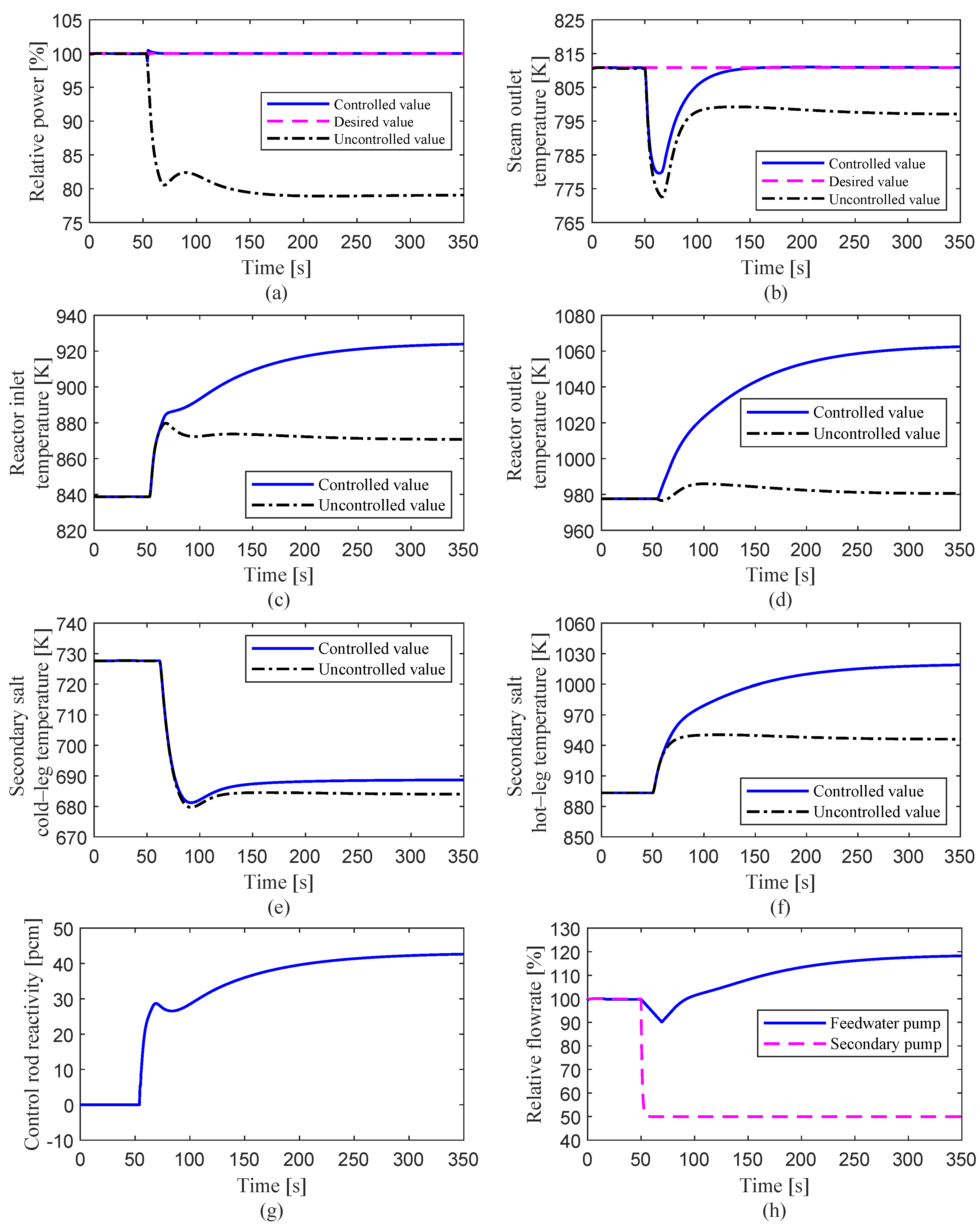
In this transient, half of the secondary molten salt pumps are assumed to fail, resulting in a rapid decrease of the mass flow rate to 50% of the steady-state value. The load demand is maintained constant at l00% FP level. Both controlled and uncontrolled cases are simulated and the response results of the system parameters are shown in Figure 15.
For the controlled case, since half of the secondary pumps stop running, the mass flow rate of the secondary salt drops rapidly in the heat exchanger and steam generator. The flow rate reduction of the secondary salt in the IHX causes that the heat produced by fission reaction in the fuel cannot be taken out in time, and then, the primary fuel temperature increases rapidly from its initial steady-state value, as shown in Figure 15c,d. The reactor power drops due to the negative reactivity introduced by the Doppler effect and the fuel temperature effect with the fuel temperature rising. Because the load demand remains at l00% FP level, the power deviation signal is sent to the control system, and the control rod begins to insert positive reactivity into the reactor to raise the power until it returns to the l00% FP level. The rapid response of the control system makes the maximum power deviation reach only 1.13%. During this transient, the hot-leg temperature of the secondary-salt initially tends to rise and the cold-leg temperature to fall. At the same time, the heat transferred from the secondary salt to the water/steam in the SG is reduced with the rapid decrease of secondary salt flow rate, so that the steam temperature drops rapidly. The error signal between the actual value of the steam temperature and its desired value is transmitted into the feedwater flow-rate controller. It can be seen from Figure 15b that the steam outlet temperature quickly reaches the set-point at 810.9 K. The performance parameters of the control system during this transient are presented in Table 3. The simulation results show that the developed control system could respond quickly to keep the reactor power and the steam temperature at their target values.
For the uncontrolled case, because the mass flow rate of the secondary salt drops rapidly after the loss-of-flow accident occurs, the heat of the primary circuit loop cannot be removed in time. It can be seen from Figure 15c,d that the fuel temperatures of the reactor inlet and outlet rise rapidly. Due to the negative feedback effect of reactivity, the reactor power quickly decreased from 100% FP to about 80% FP, and then stabilizes to a new equilibrium point. Meanwhile, the steam temperature decreases with the power drop and then rises gradually to a new equilibrium point. The final values of the reactor power and the steam temperature deviate from the desired values when the plant control system is not activated.
5. Conclusions
In this study, a simulation platform of the MSR plant was developed to study the control characteristics under normal and accident conditions. The nonlinear dynamic model of the whole system that was built in the platform consisted of a liquid-fuel reactor with a graphite moderator, an intermediate heat exchanger and a steam generator. A new control strategy was presented based on a feed-forward and feedback combined scheme, in which the reactor power control system and steam temperature control system, considering the input saturation and dead zone, were designed to adjust load changes of the plant. In order to investigate the operation and control characteristics of the MSR plant, three different transients were simulated with the developed simulation platform, which include normal load-follow operation, reactivity insertion accident and loss of flow accident. During the load-follow operation, the actual operating value of the reactor power is almost consistent with the desired load, and the range of steam temperature variation does not exceed 1K during the transient. These results show that the designed control system of the MSR plant has a fast load-follow capability and satisfactory control accuracy. For the reactivity insertion transients, the simulation results indicate that the control system could effectively deal with the rod ejection accident, thereby maintaining the stable operation of the MSR plant. In addition, both the reactor power and steam temperature are well controlled to their desired values under rod drop accident. For the loss of flow transients, the simulation results show that the developed control system not only makes the reactor continue to operate stably after one of the four primary fuel pumps fails suddenly, but also could achieve rapid adjustment of the reactor power and steam temperature according to the load demand. Furthermore, the control system could respond quickly to keep the reactor power and the steam temperature at their target values during the transient of secondary salt pump coastdown.
Author Contributions
Conceptualization, R.L. and C.L.; methodology, R.L. and C.L.; software, R.L.; validation, R.L.; formal analysis, R.L.; investigation, R.L. and C.L.; resources, R.L.; data curation, R.L. and C.L.; writing—original draft preparation, R.L.; writing—review and editing, R.L., C.L. and R.M.-J.; visualization, R.L.; supervision, C.L. and R.M.-J.; project administration, R.L.; funding acquisition, R.L. All authors have read and agreed to the published version of the manuscript.
Funding
This research was funded by Scientific Research Foundation of the Education Department of Hunan Province, China (Grant No. 18B265); High-tech Program of the Science and Technology Bureau of Hengyang City, China (Grant No. S2018G9031015321); Fundamental Research Fund for Young Teachers of the University of South China (Grant No. 190XQD064).
Institutional Review Board Statement
Not applicable.
Informed Consent Statement
Not applicable.
Data Availability Statement
Data is contained within the article, further inquiries can be directed to the corresponding authors.
Conflicts of Interest
The authors declare no conflict of interest.
Abbreviations
The following abbreviations are used in this manuscript:
| MSR | Molten Salt Reactor |
| IHX | Intermediate Heat eXchanger |
| SG | Steam Generator |
| PID | Proportion Integration Differentiation |
| ITAE | Integral Time Absolute Error |
| MSE | Mean Square Error |
| MPD | Maximum Percentage Deviation |
| ST | Settling Time |
References
- Cottrell, W.; Hungerford, H.; Leslie, J.; Meem, J. Operation of the Aircraft Reactor Experiment; Technical Report; Oak Ridge National Lab., Tenn.: Oak Ridge, TN, USA, 1955. [Google Scholar]
- Bettis, E.; Cottrell, W.; Mann, E.; Meem, J.; Whitman, G. The aircraft reactor experiment—operation. Nucl. Sci. Eng. 1957, 2, 841–853. [Google Scholar] [CrossRef]
- Robertson, R.; Briggs, R.; Smith, O.; Bettis, E. Two-Fluid Molten-Salt Breeder Reactor Design Study (Status as of 1 January 1968); Technical Report; Oak Ridge National Lab.: Oak Ridge, TN, USA, 1970. [Google Scholar]
- Taube, M.; Ligou, J. Molten plutonium chlorides fast breeder reactor cooled by molten uranium chloride. Ann. Nucl. Sci. Eng. 1974, 1, 277–281. [Google Scholar] [CrossRef]
- Luzzi, L.; Di Marcello, V.; Cammi, A. Multi-Physics Approach to the modeling and analysis of Molten Salt Reactors; Nova Science Publishers, Inc.: Hauppauge, NY, USA, 2012. [Google Scholar]
- LeBlanc, D. Molten salt reactors: A new beginning for an old idea. Nucl. Eng. Des. 2010, 240, 1644–1656. [Google Scholar] [CrossRef]
- Locatelli, G.; Mancini, M.; Todeschini, N. Generation IV nuclear reactors: Current status and future prospects. Energy Policy 2013, 61, 1503–1520. [Google Scholar] [CrossRef]
- Varma, V.K.; Holcomb, D.E.; Peretz, F.J.; Bradley, E.C.; Ilas, D.; Qualls, A.; Zaharia, N.M. AHTR Mechanical, Structural, and Neutronic Preconceptual Design; Technical Report; Oak Ridge National Lab. (ORNL): Oak Ridge, TN, USA, 2012. [Google Scholar]
- Yoder, G.L., Jr.; Aaron, A.; Cunningham, B.; Fugate, D.; Holcomb, D.; Kisner, R.; Peretz, F.; Robb, K.; Wilgen, J.; Wilson, D. An experimental test facility to support development of the fluoride-salt-cooled high-temperature reactor. Ann. Nucl. Energy 2014, 64, 511–517. [Google Scholar] [CrossRef]
- Sheu, R.; Chang, C.; Chao, C.; Liu, Y.W. Depletion analysis on long-term operation of the conceptual Molten Salt Actinide Recycler & Transmuter (MOSART) by using a special sequence based on SCALE6/TRITON. Ann. Nucl. Energy 2013, 53, 1–8. [Google Scholar]
- Fiorina, C.; Aufiero, M.; Cammi, A.; Franceschini, F.; Krepel, J.; Luzzi, L.; Mikityuk, K.; Ricotti, M.E. Investigation of the MSFR core physics and fuel cycle characteristics. Prog. Nucl. Energy 2013, 68, 153–168. [Google Scholar] [CrossRef]
- Uhlíř, J.; Juříček, V. Current czech r&d in thorium molten salt reactor (msr) technology and future directions. In Thorium Energy for the World; Springer: Berlin/Heidelberg, Germany, 2016; pp. 139–144. [Google Scholar]
- Huke, A.; Ruprecht, G.; Weißbach, D.; Gottlieb, S.; Hussein, A.; Czerski, K. The Dual Fluid Reactor–A novel concept for a fast nuclear reactor of high efficiency. Ann. Nucl. Energy 2015, 80, 225–235. [Google Scholar] [CrossRef]
- Wang, X.; Macian-Juan, R. Steady-state reactor physics of the dual fluid reactor concept. Int. J. Energy Res. 2018, 42, 4313–4334. [Google Scholar] [CrossRef]
- Wang, X.; Liu, C.; Macian-Juan, R. Preliminary hydraulic analysis of the distribution zone in the Dual Fluid Reactor concept. Prog. Nucl. Energy 2019, 110, 364–373. [Google Scholar] [CrossRef]
- Liu, C.; Li, X.; Luo, R.; Macian-Juan, R. Thermal Hydraulics Analysis of the Distribution Zone in Small Modular Dual Fluid Reactor. Metals 2020, 10, 1065. [Google Scholar] [CrossRef]
- Furukawa, K.; Arakawa, K.; Erbay, L.B.; Ito, Y.; Kato, Y.; Kiyavitskaya, H.; Lecocq, A.; Mitachi, K.; Moir, R.; Numata, H.; et al. A road map for the realization of global-scale thorium breeding fuel cycle by single molten-fluoride flow. Energy Convers. Manag. 2008, 49, 1832–1848. [Google Scholar] [CrossRef]
- Jiang, M.; Xu, H.; Dai, Z. Advanced fission energy program-TMSR nuclear energy system. Bull. Chin. Acad. Sci. 2012, 27, 366–374. [Google Scholar]
- Sides, W., Jr. Control Studies of a 1000-Mw (e) MSBR; Technical Report; Oak Ridge National Lab.: Oak Ridge, TN, USA, 1970. [Google Scholar]
- Tripodo, C.; Di Ronco, A.; Lorenzi, S.; Cammi, A. Development of a control-oriented power plant simulator for the molten salt fast reactor. EPJ Nucl. Sci. Technol. 2019, 5. [Google Scholar] [CrossRef]
- Singh, V.; Lish, M.R.; Chvála, O.; Upadhyaya, B.R. Dynamics and control of molten-salt breeder reactor. Nucl. Eng. Technol. 2017, 49, 887–895. [Google Scholar] [CrossRef]
- Zarei, M. Nonlinear dynamics and control in molten salt reactors. Nucl. Eng. Des. 2018, 332, 289–296. [Google Scholar] [CrossRef]
- Zeng, W.; Jiang, Q.; Xie, J.; Yu, T. A fuzzy-PID composite controller for core power control of liquid molten salt reactor. Ann. Nucl. Energy 2020, 139, 107234. [Google Scholar] [CrossRef]
- Zeng, W.; Zhu, W.; Hui, T.; Chen, L.; Xie, J.; Yu, T. An IMC-PID controller with Particle Swarm Optimization algorithm for MSBR core power control. Nucl. Eng. Des. 2020, 360, 110513. [Google Scholar] [CrossRef]
- Robertson, R.C. Conceptual Design Study of a Single-Fluid Molten-Salt Breeder Reactor; Technical Report; Oak Ridge National Lab., Tenn.: Oak Ridge, TN, USA, 1971. [Google Scholar]
- Shampine, L.F.; Reichelt, M.W.; Kierzenka, J.A. Solving index-1 DAEs in MATLAB and Simulink. SIAM Rev. 1999, 41, 538–552. [Google Scholar] [CrossRef]
- Burke, O. Hybrid Computer Simulation of the MSBR; Technical Report; Oak Ridge National Lab.: Oak Ridge, TN, USA, 1972. [Google Scholar]
- Sides, W. MSBR control studies: Analog simulation program; Technical Report; Oak Ridge National Lab.: Oak Ridge, TN, USA, 1971. [Google Scholar]
- Wang, P.; Wan, J.; Luo, R.; Zhao, F.; Wei, X. Control parameter optimization for AP1000 reactor using Particle Swarm Optimization. Ann. Nucl. Energy 2016, 87, 687–695. [Google Scholar] [CrossRef]
Figure 1.
Whole system diagram of the MSR plant.

Figure 2.
System nodalization of the nonlinear distributed parameter model.

Figure 3.
Variation of heat transfer coefficients with mass flow rate in the reactor core, heat exchanger (IHX) and steam generator (SG).
Figure 3.
Variation of heat transfer coefficients with mass flow rate in the reactor core, heat exchanger (IHX) and steam generator (SG).

Figure 4.
The operation temperature as a function of load.

Figure 5.
Control strategy of the MSR plant.

Figure 6.
The block diagram of power control system.

Figure 7.
The block diagram of the secondary salt temperature control.

Figure 8.
Feedforward tuning function of the mass flow rate of the secondary salt corresponding to the desired power.
Figure 8.
Feedforward tuning function of the mass flow rate of the secondary salt corresponding to the desired power.

Figure 9.
The block diagram of steam temperature control system.

Figure 10.
Simulation platform for the MSR plant nonliear model and control system in the Matlab/Simulink environment.
Figure 10.
Simulation platform for the MSR plant nonliear model and control system in the Matlab/Simulink environment.

Figure 11.
Transient responses of the system parameters during a load–follow change from 100% FP to 40% FP and, then, return at a speed of 10% FP/min. (a) Relative power; (b) Steam outlet temperature; (c) Reactor inlet temperature; (d) Reactor outlet temperature; (e) Secondary salt cold–leg temperature; (f) Secondary salt hot–leg temperature; (g) Control rod reactivity; (h) Relative flowrate.

Figure 12.
Transient responses of the system parameters under rod ejection accident. (a) Relative power; (b) Steam outlet temperature; (c) Reactor inlet temperature; (d) Reactor outlet temperature; (e) Secondary salt cold–leg temperature; (f) Secondary salt hot–leg temperature; (g) Control rod reactivity; (h) Relative flowrate.

Figure 13.
Transient responses of the system parameters under rod drop accident. (a) Relative power; (b) Steam outlet temperature; (c) Reactor inlet temperature; (d) Reactor outlet temperature; (e) Secondary salt cold–leg temperature; (f) Secondary salt hot–leg temperature; (g) Control rod reactivity; (h) Relative flowrate.

Figure 14.
Transient responses of the system parameters under primary fuel pump trip. (a) Relative power; (b) Steam outlet temperature; (c) Reactor inlet temperature; (d) Reactor outlet temperature; (e) Secondary salt cold–leg temperature; (f) Secondary salt hot–leg temperature; (g) Control rod reactivity; (h) Relative flowrate.

Figure 15.
Transient responses of the system parameters under secondary salt pump trip. (a) Relative power; (b) Steam outlet temperature; (c) Reactor inlet temperature; (d) Reactor outlet temperature; (e) Secondary salt cold–leg temperature; (f) Secondary salt hot–leg temperature; (g) Control rod reactivity; (h) Relative flowrate.


Table 1.
Main design parameters of the MSR plant [25].
Table 1.
Main design parameters of the MSR plant [25].
| Parameters | Values |
|---|---|
| Total thermal power (MW) | 2250 |
| Core height (m) | 3.96 |
| Central zone/Outer zone diameters (m) | 4.39/5.15 |
| Total delayed neutron fraction (pcm) | 264 |
| Core transit time of fuel salt (s) | 3.57 |
| External loop transit time of fuel salt (s) | 6.05 |
| Reactivity coefficient of fuel (1/K) | |
| Reactivity coefficient of graphite (1/K) | |
| Primary fuel salt | --- |
| Core inlet temperature (K) | 838.7 |
| Core outlet temperature (K) | 977.6 |
| Fuel salt flow rate (kg/s) | 11945 |
| Secondary salt | - |
| Secondary salt cold-leg temperature (K) | 727.6 |
| Secondary salt hot-leg temperature (K) | 894.3 |
| Secondary salt flow rate (kg/s) | 8971 |
| Feed water inlet temperature (K) | 644.3 |
| Steam outlet temperature (K) | 810.9 |
| Steam flow rate (kg/s) | 1487 |
| Steam pressure (MPa) | 24.82 |
Table 2.
Thermophysical Properties of Fuel Salt, Graphite, Secondary salt, Tube Wall and Water/Steam.
Table 2.
Thermophysical Properties of Fuel Salt, Graphite, Secondary salt, Tube Wall and Water/Steam.
| Parameters | Values |
|---|---|
| Fuel salt density (kg·m−3) | |
| Fuel salt specific heat ( J·kg−1·K−1) | 1357 |
| Graphite density (kg·m−3) | 1843 |
| Graphite specific heat (J·kg−1·K−1) | 1760 |
| Fuel-graphite heat transfer coefficient ( W·m−2· K−1) | 6047 |
| Secondary salt density (kg·m−3) | |
| Secondary salt specific heat (J·kg−1·K−1) | 1507 |
| Tube wall density (kg·m−3) | 8671 |
| Tube wall specific heat (J·kg−1·K−1) | 569 |
| IHX fuel salt-wall heat transfer coefficient (W·m−2· K−1) | 13,786 |
| IHX secondary salt-wall heat transfer coefficient (W·m−2·K−1) | 9533 |
| Supercritical water/steam density (kg·m−3) | + 12,748 |
| Supercritical water/steam specific heat (J·kg−1·K−1) | |
| SG secondary salt-wall heat transfer coefficient (W·m−2·K−1) | 4860 |
| SG water inlet-wall heat transfer coefficient (W·m−2·K−1) | 10,055 |
| SG steam outlet-wall heat transfer coefficient ( W·m−2·K−1) | 8265 |
Table 3.
Quantitative evaluation results of the control performance.
| Parameters | Load Follow Transient | Reactivity Insertion Transients | Loss of Flow Transients | ||
|---|---|---|---|---|---|
| Rod Ejection Accident | Rod Drop Accident | Primary Fuel Pump Trip | Secondary Salt Pump Trip | ||
| IATEP | |||||
| IATET | |||||
| MSEP | |||||
| MSET | |||||
| MPDP(%) | |||||
| MPDT(%) | |||||
| STP(s) | − | 25 | 21 | 16 | 19 |
| STT(s) | − | 63 | 62 | 105 | 112 |
Publisher’s Note: MDPI stays neutral with regard to jurisdictional claims in published maps and institutional affiliations. |
© 2021 by the authors. Licensee MDPI, Basel, Switzerland. This article is an open access article distributed under the terms and conditions of the Creative Commons Attribution (CC BY) license (https://creativecommons.org/licenses/by/4.0/).
Share and Cite
MDPI and ACS Style
Luo, R.; Liu, C.; Macián-Juan, R. Investigation of Control Characteristics for a Molten Salt Reactor Plant under Normal and Accident Conditions. Energies 2021, 14, 5279. https://doi.org/10.3390/en14175279
AMA Style
Luo R, Liu C, Macián-Juan R. Investigation of Control Characteristics for a Molten Salt Reactor Plant under Normal and Accident Conditions. Energies. 2021; 14(17):5279. https://doi.org/10.3390/en14175279
Chicago/Turabian StyleLuo, Run, Chunyu Liu, and Rafael Macián-Juan. 2021. "Investigation of Control Characteristics for a Molten Salt Reactor Plant under Normal and Accident Conditions" Energies 14, no. 17: 5279. https://doi.org/10.3390/en14175279
Note that from the first issue of 2016, this journal uses article numbers instead of page numbers. See further details here.