
Analysis of Natural Hydraulic Fracture Risk of Mudstone Cap Rocks in XD Block of Central Depression in Yinggehai Basin, South China Sea

1
Institute of Unconventional Oil & Gas, Northeast Petroleum University, Daqing 163318, China
2
Key Laboratory of Continental Mudstone Hydrocarbon Accumulation and Efficient Development, Ministry of Education, Northeast Petroleum University, Daqing 163318, China
3
Hainan Branch of China National Offshore Oil Corporation Ltd., Haikou 570100, China
*
Author to whom correspondence should be addressed.
Energies 2021, 14(14), 4085; https://doi.org/10.3390/en14144085
Submission received: 18 May 2021
/
Revised: 2 July 2021
/
Accepted: 2 July 2021
/
Published: 6 July 2021
(This article belongs to the Collection State of the Art Geo-Energy Technology in China)
Abstract
:The Yinggehai Basin is an important Cenozoic gas bearing basin in the South China Sea. With the gradual improvement of gas exploration and over-development in shallow layers, deep overpressured layers have become the main target for natural gas exploration. There are no large-scale faults in the strata above the Meishan Formation in the central depression, and hydraulic fracturing caused by overpressure in mudstone cap rocks is the key factor for the vertical differential distribution of gas. In this paper, based on the leak-off data, pore fluid pressure, and rock mechanics parameters, the Fault Analysis Seal Technology (FAST) method is used to analyze the hydraulic fracture risk of the main mudstones in the central depression. The results show that the blocks in the diapir zone have been subjected to hydraulic fracturing in the Huangliu cap rocks during the whole geological history, and the blocks in the slope zone which is a little distant from the diapirs has a lower overall risk of hydraulic fracture than the diapir zone. In geological history, the cap rocks in slope zone remained closed for a longer time than in diapir zone and being characterized by the hydraulic fracture risk decreases with the distance from the diapirs. These evaluation results are consistent with enrichment of natural gas, which accumulated in both the Yinggehai Formation and Huangliu Formation of the diapir zone, but it only accumulated in the the Huangliu Formations of the slope zone. The most reasonable explanation for the difference of the gas reservoir distribution is that the diapirs promote the development of hydraulic fractures: (1) diapirism transfers deep overpressure to shallow layers; (2) the small fault and fractures induced by diapir activities weakened the cap rock and reduced the critical condition for the natural hydraulic fractures. These effects make the diapir zone more prone to hydraulic fracturing, which are the fundamental reasons for the difference in gas enrichment between the diapir zone and the slope zone.
1. Introduction
Hydraulic fracturing, also known as natural hydraulic fracturing and hydraulic extensional fracturing, is a common kind of geological phenomenon which refers to fractures caused by the increase of pore fluid pressure [1,2,3,4,5]. It covers the hydraulic effects on intact rocks and fractured rocks, which play an important guiding role in fluid migration, oil and gas preservation, and the safe exploitation of oil and gas fields. Research on hydraulic fracturing began in the late 1960s [1]. In a study on the law of joint development, Secor proposed the mechanism of natural tensile fractures and pointed out that the fracture caused by fluid overpressure can open original fractures in the formation while also playing an important role in the migration of groundwater, oil and gas, and ore-forming fluids [6,7]. After that, Phillips formally proposed the concept of hydraulic fracturing in his study of the formation mechanism of mineralized normal faults in Wales, the UK, which he described as the process of fracture expansion caused by the increase of pore fluid pressure within the fracture [2]. In 1990, Sibson analyzed the migration process of abnormally high pressure fluid near the fault, described the dynamic process of fault hydraulic rupture, and pointed out that this process is periodic, intermittent, and pulsating [8]. Subsequently, the research on hydraulic fracture was deepened, many overpressure basins around the world were analyzed and studied, and it was clearly pointed out that hydraulic fracture is a potential risk leading to oil and gas leakage [9]. For example, in the research of Timor Sea, they pointed out that the fault reactivity caused by hydraulic fracturing is the main cause of oil and gas leakage [10].
Through the study of the development of hydraulic fracture, the hydraulic fracture phenomenon is similar to the fault valve mechanism [11]. It has the characteristics of episodic eduction, especially in the overpressure basins. When the pore fluid pressure exceeds the rock fracturing pressure, rocks will begin fracturing leading to highly permeable channels for fluid to flow into which carries a large quantity of minerals through the fractures. In the process, pore fluid pressure is released and gradually reduced. The mineral cementation, precipitation, and pressolution gradually decreases the width of the fractures which finally forms a closed hydraulic fracture until the fluid pressure rises to enter the next “broken-closed” cycle.
Studies have also shown that these hydraulic fractures have specific geological characteristics both macroscopically and microscopically. For example, due to the periodic activities of hydraulic fracturing, different periods of hydraulic fracturing and fluid migration lead to changes in the formation structure and in 3D seismic imaging. Furthermore, the amplitude intensity is usually increased or decreased locally along the reflection layer and it forms the vertical continuous fuzzy zone and pipe features [12,13]. In the field of outcropping, it is mainly manifested as extensional fractures extending perpendicular to the direction of minimum principal stress and filled by quartz, calcite, and gypsum veins [14,15,16]. The multi-stage filling of fractures by fluid minerals can also be observed under a microscope.
How to effectively and accurately determine the critical condition of hydraulic fracturing is particularly important to quantitatively evaluate the periodicity of hydraulic fracturing. Through a lot of experience, many scholars regard 85% of the overburden lithostatic pressure as the critical pressure for hydraulic fracturing to occur [6,17,18,19,20]. Similarly, a study on the Norwegian Snorre field found that when the pore fluid pressure at the top of the reservoir reaches 82% of the static pressure, approximately equal to the minimum horizontal principal stress, hydraulic fracturing increases the permeability of mudstone and leads to the escape of oil and gas from the reservoir [21]. Some investigators propose that the critical pore fluid pressure for hydraulic fractures is the sum of the principal of minimum stress and the tensile strength of cap rock [1,22,23,24,25]. Gaarenstroom defined the difference between the minimum horizontal principal stress and pore fluid pressure as the retention capacity in his study on the risk of hydraulic fracture in the cap rock of the North Sea Basin. The larger the pore fluid pressure is, the retention capacity will be smaller, and the risk of hydraulic fracture in the cap rock will be greater. He found that when the retention capacity is lower than 7 MPa, the risk of hydraulic fracture will significantly increase [24]. Most of these evaluation methods only consider the risk of hydraulic tensile fracture of rock and ignore the tensile strength of rock. However, the actual cap rock is often heterogeneous, especially when there is strong and weak interbedding in the cap rock (sandstone and mudstone are both distributed), and the cap rock may form shear fracture or mixed-mode fracture failure. Therefore, this simple evaluation method is obviously not applicable to evaluate the hydraulic fracture risk of deep overpressure cap rock such as Yinggehai Basin. At present, we mainly use the Fault Analysis Seal Technology (FAST) for the hydraulic fracture evaluation [10,26]. The Fast evaluation method is a comprehensive method proposed by Mildren et al. in 2002 based on the principle of rock rupture. This method can be used to evaluate the conditions and types of faults or fractures formed by rock rupture and the conditions under which the faults reactivity or maintain stability. The basic principle is whether the formation fluid pressure under the current stress and pressure conditions can cause the structure to reactivate or remain stable. The quantitative evaluation results of the FAST method are in good agreement with the actual situation, and it has been widely used in oil and gas field production and gas storage [10,26]. The data required by the FAST method mainly include the characteristics of present stress field, fluid pressure, friction strength, and cohesion of the rock. In this study, although there is a lack of large-scale fault development in the study area, a large number of fractures are still developed in the cap rock. Therefore, we can still use the FAST method to evaluate whether hydraulic fracture will be induced by fluid pressure in the cap rocks. It can be used to evaluate not only the risk of complete cap fracture, but also the risk of the occurrence of pre-existing extensional fracture and shear fracture before movement takes place, which is an effective method for studying the integrity of cap rocks.
In recent years, many scholars have done a lot of research on the effectiveness of cap rocks. We keep focusing on the study of hydraulic fracturing on the effectiveness of cap rock and the risk of oil and gas leakage and have used this method to analyze hydraulic fractures of cap rocks in several blocks in different basins [27,28,29,30,31,32] which have achieved some good results. Especially in the study area, a lot of preliminary research has actually been done on the cap rocks, such as the macro- and micro-development characteristics and sealing mechanism and sealing ability of the cap rocks. Some scholars have made preliminary studies on the migration and preservation conditions of natural gas caused by hydraulic fracturing, but most of them focus on theoretical and qualitative analysis. In order to further study the influence of hydraulic fracturing on natural gas enrichment in different structural locations, the same FAST evaluation method was used in this study. Based on the in-situ stress characteristics, mudstone mechanics and pore fluid pressure are used to analyze the potential of mudstone hydraulic fracturing in present conditions, and combine with the paleo-pressure to analyze the hydraulic fracture risk in geological history to discuss its influence on gas accumulation and provide theoretical guidance for oil and gas exploration in basins with the same geological background.
2. Geological Setting
The Yinggehai Basin is a typical Cenozoic sedimentary basin on the northwestern continental shelf of the northern South China Sea [33,34,35,36,37,38]. The northeast side of the basin adjoins the southern uplift of the Beibu Gulf Basin and the Hainan Uplift. The west side is connected to the Kunsong Uplift and it extends to the Hanoi Depression in Vietnam. This basin is 750 km long and 200 km wide, with an area of about 11.3 × 10⁴ km2. Yinggehai Basin is located in the convergence zone of the Eurasian, Pacific, and Indo-Australian plates [38]. Under the background of the expansion of the South China Sea, it is restricted by the strike-slip activity of the Red River Fault and the compression of the plate [39]. The basin is distributed in a rhomboid shape along the NW-SE direction, and composed of four first-order structural units: The Central Depression, The Yingdong Slope Zone, The Yingxi Slope Zone, and The Lingao Uplift (Figure 1).
The basin has experienced multi-stage regional tectonic movements, which can be divided into four stages: Eocene—Early Oligocene rift period, Late Oligocene fault—Depression period, Early—Middle Miocene post-rift thermal subsidence period, and Late Miocene—Quaternary accelerated subsidence period. Drilling data shows that the strata drilled from bottom to the top of the basin are as follows: The Lingtou Formation, The Yacheng Formation, The Lingshui Formation, The Sanya Formation, The Meishan Formation, The Huangliu Formation, The Yinggehai Formation, and The Ledong Formation (Figure 2).
The Central Depression developed a series of nearly N–S orientations diapir structures, which is distributed in an echelon arrangement [35,37]. The research area is located in the southeast of the central depression in the Yinggehai Basin (Figure 1), which is characterized by a lack of fracture, rapid settlement, high temperature and high pressure, and it has more mudstone and less sand. The Yinggehai Basin experienced rapid subsidence in the late structural period, with a deposition rate of 500–1400/Ma, and the Cenozoic maximum sedimentary thickness is over 17 km [34]. Test data of the both the drill pipe and the cable indicates that deep formation pressures below 4000 m exceed 100 MPa, with a maximum pressure factor of 2.30. The numerical simulation of different overpressure formation mechanisms shows that due to the limited abundance of organic matter and the weak contribution of hydrocarbon generation and compression, the abnormally high pressure of the formation comes from the under-compaction caused by the rapid deposition of mudstone, and the conduction effect of the diapir structure acting on the deep overpressure [40,41].
The Ledong area has developed mainly two types of traps, tectonic lithologic trap under the diapir background and lithologic trap group developed within the background context of gravity flow deposition. The Sanya Formation and the Meishan Formation in the Miocene are shallow marine facies mudstones which is the main source rocks in study area. The mudstones in Huangliu Formation and the Yinggehai Formation in upper Miocene and Quaternary Formation are the main cap rocks for nature gas. In addition, these strata are the main reservoir-forming assemblage in the study area (Figure 2). The longitudinal enrichment layers of natural gas are quite obviously different in various structural positions. In the diapir zone, oil and gas are mainly enriched in the shallow strata (Yinggehai and Ledong Formation), such as XD-A area and XD-B area, but natural gas is generally enriched in deeper layers (the Meishan and the Huangliu Formation) and in the slope zones which are far from the diapirs, such as XD-C, XD-D, XD-E area (Figure 3). As a whole, the farther from the diapir, the deeper the gas enrichment. Published literature indicates that there are signs of large-scale fluid migration in the Yinggehai Basin (e.g., gas chimney, pockmark, and pipe) the origins of which many scholars attribute to hydraulic fracturing by overpressure fluid [36]. We speculate that the difference of vertical distribution of natural gas may be caused by the difference in hydraulic fracture strength in different structural positions. Therefore, based on the in-situ stress in the study area, this paper will use the fluid pressure in mudstone and the mechanical parameters of mudstone to analyze the risk of hydraulic fracture in the diapir area and the slope area in the long-term geological historical course as well as the current period. Furthermore, we clarify the main reasons for the natural gas differentially accumulated in the vertical between the different structural zones.
3. Methods
3.1. Principle of Cap Rock Hydraulic Fracture Evaluation
There are two kinds of hydraulic fracture modes of cap rock under the dominance of fluid, namely, the fracture of intact cap rock and the re-opening of pre-existing fractures. The constant increase of pore fluid pressure leads to the gradual decrease of the effective stress on the cap rocks, and eventually, pressure is relieved through hydraulic fractures [4].
The fracture mode on cap rocks is controlled by two factors, the tensile strength of cap rock (T) and its differential stress (S1 − S3) [1,42,43]. When the S1 − S3 of the stratum is less than 4 times the tensile strength, extensional fractures are formed; when the S1 − S3 is more than 6 times its tensile strength, it results in compressional shear fractures; the tensile strength and shear mixing fractures occur in relation to the above two conditions when the S1 − S3 is more than 4 times and less than 6 times the tensile strength (Table 1) [26]. For the intact cap rocks, in the case of extensional fractures, extensional shear fractures, and shear fractures, the fracture pressure (P) of cap rock corresponds to A1C1, A2C2, and A3C3, respectively (see points in Figure 4) [42]. However, for cap rocks with pre-existing fractures, hydraulic fractures are always re-opening along the weak surface. We used the incoherency of envelope to characterize fracture conditions, fracture pressure (P) for extensional fractures, extensional shear fractures, and shear fractures which respectively correspond to Figure 4 B1C1, B2C2, and B3C3. Analysis shows that the existence of early fractures largely increases the risk of hydraulic cracks in the cap rocks. Therefore, in order to determine the hydraulic fracture pressure, the fracture mode of the cap rock must be determined first.
Where P is fracture pressure (MPa), S1 is maximum principal stress (MPa), S3 is minimum principal stress (MPa), S1 − S3 is differential stress (MPa), Sn is normal stress (MPa), T is tensile strength of rock (MPa), C is cohesion (MPa), τ is shear stress (MPa), μ is coefficient of friction.
3.2. Parameters of Cap Rock Hydraulic Fracture Evaluation
Based on the above description, the development of hydraulic fracture depends on the pore fluid pressure, the characteristics of the in-situ stress field, and the mechanical properties of the cap rock. Among them, pore fluid pressure and mechanical parameters of cap rocks can be obtained through formation tests and laboratory tests. Therefore, in order to be able to quantitatively evaluate the hydraulic fracture risk of cap rock, it is necessary to define the in-situ stress characteristics of the study area.
3.2.1. Vertical Principal Stress
The vertical principal stress mainly comes from the rock gravity of the overburden strata. Therefore, it can be obtained by integrating density log data. Because the Yinggehai Basin is in the South China Sea, it is necessary to consider the effect of seawater on the vertical principal stress [44] (Equation (1)).
where Sv is the vertical principal stress (MPa), ρw is the density of water(1.03 g/cm3 for Yinggehai Basin), hw is the water depth(average depth is 65 m in the study area), ρc is the density of overburden layers (g/cm3), g is the gravitational acceleration constant (N/kg), h is the burial depth below sea level (m). However, there are always some problems when calculating vertical principal stress. For example, the density logging usually does not start from the sea bottom or surface. The missing density value can be converted from the check-shot velocity data to the density data through the Nafe-Drake transformation formula [45].
3.2.2. Horizontal Principal Stress
Horizontal principal stress is usually the most difficult to interpret. At present, a relatively reliable method is extracted from hydraulic pressure tests [46]. However, these tests have not been widely used on drilling. In this study, we have chosen to use pumping pressure tests data to analyze horizontal principal stress which can be classified as FITs (Formation Integrity Tests), LOTs (Leak-Off Tests), and XLOTs (Extended Leak-Off Tests) [47]. They are curves of bottom hole pressure and pumped mud volume/time, and can be distinguished by the difference between the number of pumping cycles and the point at which pumping is ceased [47] (Figure 5a). LOTs are performed in the formation below the casing shoe, and its primary purpose is to determine the maximum mud weight that could be allowed without drilling risk (formation loss) [24]. Whereas LOTs are not pressurized after the loss pressure is reached to avoid further formation damage, XLOTs are pressurized after the loss pressure is reached, even with multiple pressure cycles performed to obtain more information. Engineering practice shows that a classic single-cycle XLOT curve includes Leak-off Pressure (LOP), Formation Break-down Pressure (FBP), Fracture Propagation pressure (FPP), Instantaneous Shut in Pressure (ISIP), Fracture Closure Pressure (FCP) (Figure 5b–d). Of these points on the curve, LOP is the first point that deviates from the linear relationship between pressure and cumulative mud volume, which can be considered to be the point where the fluid begins to penetrate into the formation, and the rock begins to deform inelastically. Thus, the lower envelope of all LOP data can be used to represent horizontal minimum principal stress [24].
During the XLOT test, the failure pattern of the wellbore wall is very similar to the hydraulic fracturing in cap rock. The difference is that hydraulic fracturing detects the wellbore conditions through technology and then selects the target interval without fractures. The presence of fractures causes the formation break-down pressure to be close to the fracture reopening pressure, and the tensile strength of wellbore wall is approximately zero [48,49]. Thus, the Hubbert–Willis equation [48] can be simplified to
where SHmax and Shmin are the maximum and minimum horizontal principal stress, respectively (MPa); FRP is the fracture reopening pressure (MPa); and Pp is the pore pressure (MPa).
3.2.3. Pore Fluid Pressure and Mechanical Parameters of Cap Rocks
The current pore fluid pressure is derived from formation Drill Stem Test (DST) and Modular Formation Dynamics Test (MDT) data and drilling fluid weight. The palaeo-pressure data was derived from CNOOC (China National Offshore Oil Corp., Beijing, China).
The mechanical parameters of cap rocks can be tested by direct tensile test and the Brazilian tensile test. However, these two methods have high requirements for sample preparation and low success rate. Considering the limited core samples, conventional triaxial compression test was chosen for this paper. Specifically, we used the GCTS Rapid Triaxial Rock Test System, and the instrument model is RTR-2000. Through tests, we measured the stress-strain curves of rock under different confining pressures and assumed that the tensile strength envelope in the tensile region conforms to the Griffith fracture criterion; the tensile strength of rock can be estimated by its relation to the cohesion, which is usually approximately twice the tensile strength.
4. Results
4.1. In-Situ Stress and Mechanical Properties of the Cap Rock
4.1.1. Pore Fluid Pressure
Drill pipe or wireline test data obtained from DST and MDT show that most of the wells in the Yinggehai Basin have encountered abnormal high fluid pressure formations in the middle and deep layers. In the study area, gas reservoirs are distributed in both overpressure and normal pressure layers, and the Huangliu Formation contains the main regional cap rocks for overpressure gas reservoirs in the deep layer. The maximum fluid pressure can be reached 96 MPa and the fluid pressure coefficient is close to 2.3. The fluid pressure increases with the burial depth longitudinally, and the magnitude of overpressure in the diapir zone is stronger than the slope zone at the same depth. This overpressure distribution may be due to the fact that overpressure can be transferred from deep to shallow layers in diapir zone.
4.1.2. Vertical Principal Stress
In this study, the density–depth relationship of five Wells in the three blocks of the study area (Figure 6a, Equation (2)) was used to integrate to obtain the magnitude of vertical principal stress in the study area (Figure 6b, Equation (3)). The vertical stress gradient increases with depth and is close to 22.8 MPa/km in Huangliu Formation.
Sv = 0.010576h1.0949 − 0.607
4.1.3. Horizontal Principal Stress
Minimum Horizontal Principal Stress
According to the statistics of the LOTs and XLOTs data from the study area, they can be divided into three types. The first type is the XLOTs, although only one pressure cycle was performed, we can observe the FBP, FPP, and ISIP clearly (Figure 5b). In the second category, the well was shut in immediately after LOP was observed, with no significant pressure drop and no formation fracture (Figure 5c). The third category of data is that the formation did not fracture, and no significant losses were observed (Figure 5d). We cannot determine whether the shut-in was performed before or after the LOP was reached, but it can be inferred from the data of the offset wells.
For the first category of date, ISIP can better reflect Shmin than LOP, so ISIP is chosen to represent Shmin. For the second category, Shmin was represented by LOP. As for the third category of data, it is not possible to determine whether the maximum pressure is between FIT and LOP or between LOP and FBP, since no LOP formation was observed and no fracture occurred. However, compared to the offset well, the later well date can be used as the upper limit of Shmin. Synthesizing three categories of data analysis in the study area, the Shmin can be described by ISIP and LOP data in depths (Figure 7).
Maximum Horizontal Principal Stress
According to the XLOT curve of the study area, Equation (2) is used to calculate the maximum horizontal principal stress. The tensile strength is approximated by the difference between the fracture pressure and the loss pressure. The results show that the in-situ stress state is Sv > SHmax > Shmin when the depth is above 2700 m and corresponds to the normal faulting stress regime. The in-situ stress state is SHmax > Sv > Shmin when the depth is below 2700 m and corresponds to the strike-slip faulting stress regime (Figure 7). The horizontal principal stress is obviously affected by the pressure-stress coupling, that is, the horizontal principal stress shows a trend of significant increase with the increase of fluid pressure.
4.1.4. Geomechanical Properties of the Cap Rock
The Huangliu Formation cap rock in the Yinggehai Basin is a shallow-marine-facies deposit composed of mudstone which is a regional cap layer widely developed in the study area with a maximum thickness of up to 400 m. The mechanical properties of the cap rock directly control the fracture conditions and the required fracture pressure. As mentioned above, we used the GCTS Rapid Triaxial Rock Test System to test the mechanical parameters of cap rocks. The laboratory temperature was 25 °C, the humidity was 50%, the strain rate was 0.03 mm/min, and the sample was a cylinder with a diameter of 25 mm and a height of 50 mm taken from cap rock in the Huangliu Formation’s well cores. According to the real geological background, the pore fluid pressure was set to 55 MPa. Through data processing and calculation, the friction coefficient (μ) and cohesion (C) were 0.426 and 17 MPa. The tensile strength of rock is 8.5 MPa (Figure 8). Furthermore, the well logging data can be used to calculate the tensile strength of the strata by Equation (5) [54]. The prediction of tensile strength is shown in Figure 9.
where T is tensile strength (MPa), Ed is dynamic modulus of elasticity (MPa), Vsh is mudstone content (%), and K is the correction coefficient obtained by fitting the experimental test data and logging calculation data, which is approximately 16 (dimensionless).
4.2. Risk of Hydraulic Rupture of Mudstone Cap Rock
Hydraulic fracture is characterized by episodic opening, which not only provides channels for fluid migration, but also damages the integrity of cap rock, leading to the loss of oil and gas. It is, therefore, of great significance for evaluating the effectiveness of oil and gas traps and finding favorable exploration targets to determine whether hydraulic fracturing is occurring or about to occur in the cap rock.
4.2.1. Risk of Hydraulic Fracture of Cap Rock in Present Conditions
The development of hydraulic fractures depends on the pore fluid pressure, the characteristics of in-situ stress field, and the mechanical properties of the cap rock. As mentioned above, when the differential stress of the cap rock is less than four times the tensile strength, the cap rock will suffer extensional fracture; when the difference stress is more than six times the tensile strength, the cap rock will suffer shear fracture; and when the difference stress is between the two conditions, the cap rock will suffer tensile shear mixed fracture (Table 1). The comparison of tensile strength and differential stress shows that the differential stress of strata at different depths in the study area is generally less than four times the tensile strength, and the difference between differential stress and four times the tensile strength gradually increases with the increase of depth, which means that extensional fracture is always developed in the strata. Due to the different fracture conditions of the cap rocks with early fracture development and those without fracture development, the existence of fractures increases the risk of hydraulic fracture of the cap rocks to a large extent and makes the cap rocks more prone to hydraulic fracture. Considering the geological background of early strike-slip fault activity and diapir structure, subsequent hydraulic fracturing will occur along the pre-existing fracture weak surface. In this paper, the minimum horizontal principal stress is used to represent the minimum fracture pressure required for hydraulic fracturing of cap rock, and the ratio of fluid pressure to the minimum fracture pressure is defined as the hydraulic fracture risk factor of cap rock (Rf) (Equation (6)). When its value is greater than 1, it indicates that hydraulic fracture has occurred in fractured cap rock.
where Rf is the hydraulic fracture risk factor of cap rock, PHF is the minimum hydraulic fracture pressure (MPa), equal to the minimum horizontal principal stress (MPa), Pp is the pore fluid pressure (MPa).
Five blocks with relatively complete data in the diapir zone and the slope zone in Ledong area were selected for analysis and evaluation. We interpolated the Rf values from the 19 wells to generate a contour map of Rf (Figure 10). The results show that at the top of XD-A and XD-B reservoirs have developed strong overpressure so that the Rf ratio is greater than 1, means that it is still in the period of hydraulic leakage. Blocks XD-C, XD-D, and XD-E maintain hydraulic seal in Huangliu Formation. It can be concluded from the plane variation of the risk coefficient that the closer to the center of the diapir, the higher the fracture risk, which reflects the control effect of the burial depth of the cap rock and the degree of overpressure development on the gas reservoir distribution.
4.2.2. The Evolution Process of Hydraulic Fracture in Cap Rock
At present, the natural gas in the Yinggehai Basin is enriched in multiple reservoirs, and the enrichment of shallow oil and gas reflects the fracture of cap rock during the historical period, which leads to the migration of natural gas from deep to shallow layers. The risk of cap rock hydraulic fracture in geological history mainly depends on the paleo-fluid pressure, paleo-in-situ stress, and the strength of cap rock (cap rock fracture pressure) in geological history. Compared with the in-situ stress in present conditions, it is very difficult to recover the palaeo-stress which is controlled by many factors (e.g., depth, tectonic activity, and palaeo-pressure) [55]. Due to the limitation of the original data, the subsequent research of this paper assumes that the tectonic environment is stable after the middle Miocene, and the burial history is combined with the current stress data to analyze the magnitude of the palaeo-stress. Based on that assumption, the vertical principal stress at the same depth varies little in geological history, but the magnitude of horizontal principal stress is mainly composed of tectonic stress and the Poisson effect of overburden, so the strength of tectonic activity has a great influence on it. As stated earlier, the Yinggehai Basin experienced multiphase tectonic evolution, in middle-late Miocene into a period of rapid subsidence and basin tectonic activity is weak overall. The strata of Meishan Formation and above formations generally not develop large faults, and the faults in deep layers mostly have stop activities. The Ledong area is in a relatively stable tectonic environment. The key horizon of this study is the cap layer of the Huangliu Formation and Meishan, which are overpressured strata developed during the period of structural stability. Therefore, the present in-situ stress (Figure 7) combined with burial history can be roughly used in this paper to predict the magnitude of paleo-stress under a stable tectonic setting (Figure 11). Although there are some uncertainties in the prediction of paleo-stress, it can still provide some reference for the evaluation of whether hydraulic fracture occurs in the cap rock. In addition, compaction is the main factor to control the variation of rock tensile-strength with similar mineral content, and compaction is closely related to the stress on the stratum. Therefore, this paper also assumes that the tensile strength of mudstone cap rocks in different geological periods has little difference under the same burial depth. The relationship between differential stress and tensile strength in the study area should also be referred to when studying whether hydraulic fracture occurs in the cap rock in historical periods. As shown in Figure 9, the differential stress from shallow to deep layers is always less than four times tensile strength, which indicates that even in geological historical periods, the hydraulic fracture of intact rock is dominated by tensile fracture. Therefore, approximate vertical fractures developed in the diapir structural zone confirm the conclusion of extensional fracture in the rock [41]. We calculated hydraulic fracture risk factor (Rf), the ratio of paleo-fluid pressure, and rock fracture minimum pressure in different periods in cap rock to evaluate whether hydraulic fracturing occurred in the historical period.
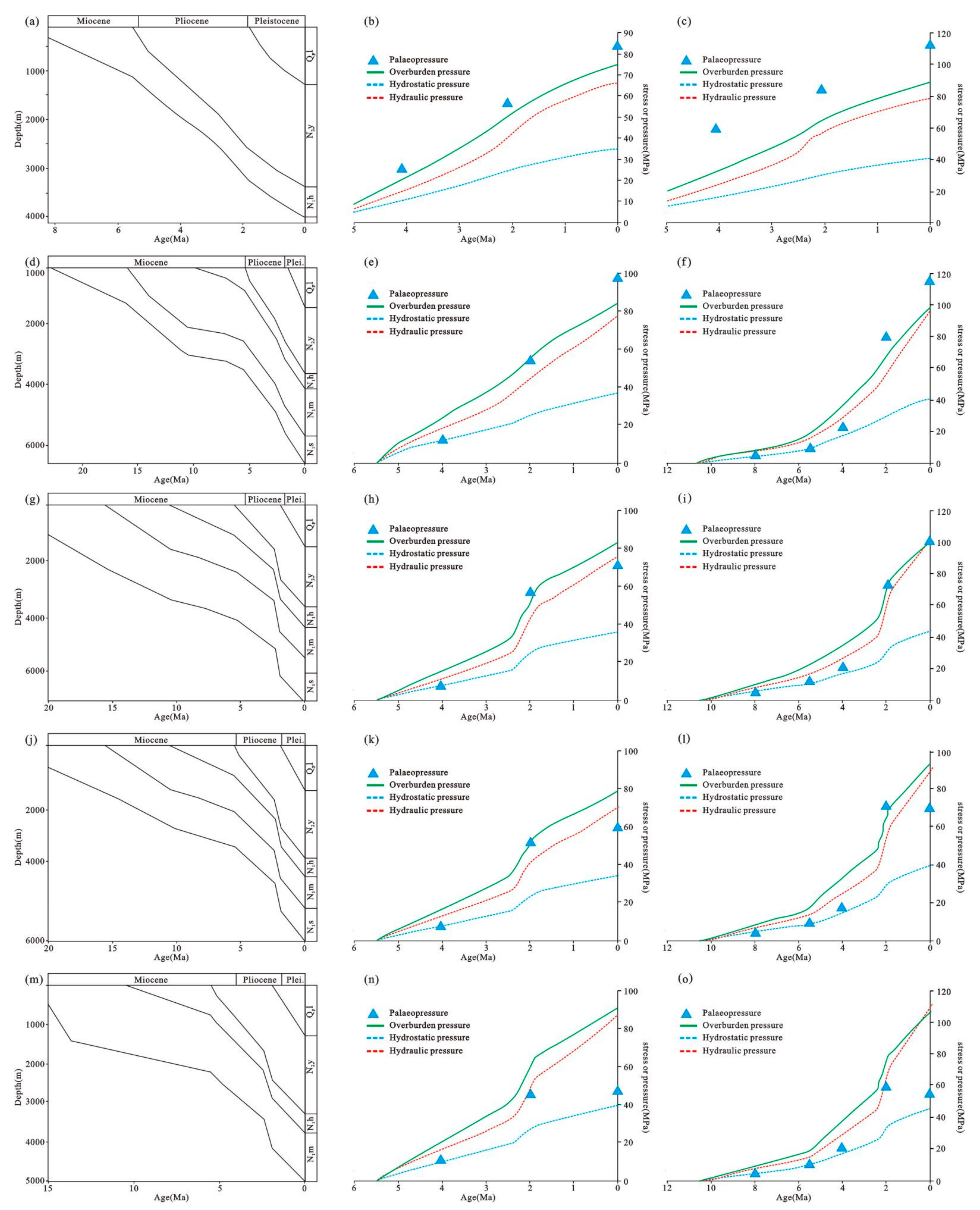
The paleo-pressure data of hydraulic fracture evaluation are mainly from CNOOC. We evaluated gas reservoirs in the diapir zone and slope zone. Taking XD-A area as an example in the diapir zone, it can be seen that the paleo-fluid pressure is consistently higher than the hydraulic fracturing pressure of rock strata, indicating that with the passage of geological time, the hydraulic fracturing of cap rock continues to occur in Huangliu and Meishan Formation, providing an effective channel for oil and gas migration, enabling natural gas to enter the shallow Ledong Formation and Yinggehai Formation from the deep source rock and finally to form reservoirs (Figure 11b,c). The evolution process of hydraulic fracture of XD-B block is similar to that of the XD-A block. Although the hydraulic fracture started later than XD-A block, both the cap rocks of Huangliu and Meishan Formations were in the stage of hydraulic fracturing after 2 Ma (Figure 11e,f) and finally formed shallow gas reservoirs or showing gas-bearing properties (Figure 11e,f). In relatively distant slope zones, the XD-C and XD-D blocks, in the historical period, hydraulic fracture occurred about 2 Ma in Huangliu and Meishan Formation, but later, as the pressure was released, hydraulic fractures began closing again; only a small amount of oil and gas shows but failed to form oil and gas accumulation (Figure 11h,i,k,l). The XD-E block, which is farthest from the diapir, has not reached the hydraulic fracture pressure in the historical period until now, although the pressure has accumulated to a certain extent (Figure 11n,o). The cap rocks have always been sealed, and the oil and gas have not migrated or diffused through the layers, and finally accumulated in the sandstone of the Meishan Formation (Figure 3). From the whole evaluation results, the evolution of hydraulic fracture of cap rock has obvious characteristics. It can be divided into three categories, “continuous fracturing” in diapir zones, “continuous sealing” in slope zones, and “sealed-fractured-sealed” in between.
5. Discussion
5.1. The Uncertainty of Calculation in Hydraulic Fracture Risk Factor
The evaluation method of this study is the FAST method which can be used to evaluate both tensile and shear hydraulic fracture. We first determined the hydraulic fracture mode of cap rock, and then selected the appropriate evaluation method for evaluation. In the evaluation process, we fully applied the formation test data of the oil field to analyze the hydraulic fracture risk of the cap rock under real geological conditions as far as possible. In the measurement of rock mechanics parameters, we also restored the real geological conditions to the greatest extent within the scope of instrument testing.
In spite of our efforts, there is still some uncertainty in the determination of Rf, mainly because it is controlled by many factors, including the state of paleo-stress, mechanical properties of rock in historical period, and paleo-fluid pressure. The stress field can be divided into three scales [56]: the first-order stress field mainly comes from the plate driving force; the second-order stress field is derived from major intraplate stress, such as isostatic compensation, glaciation retreat, and lithospheric bend; and the third-order stress field is determined by stress and strain such as faults activity, local intrusion, horizontal detachment, and density inversion. The influences of the various factors described above bring great difficulties to the evaluation of the current stress field, especially the determination of the maximum horizontal principal stress. In our study, the in-situ stress is determined based on two assumptions. Firstly, it is assumed that the in-situ stress in the study area is homogeneous as is the magnitude of the in-situ stress in different locations. Secondly, it is assumed that the influence intensity of various factors on the in-situ stress in the geological history period is the same as that of today, so that the magnitude of the ancient in-situ stress can be obtained from the burial-depth. In addition, the study in this paper ignored the heterogeneity of stratigraphic sedimentation in the same geological history period and assumed a consistent tensile strength of rocks, which was obviously inconsistent with reality. However, due to the limited core samples, we cannot test drill cores at different locations, so more tensile strength data could not be obtained. In theory, at some locations in the cap rock, due to the influence of the rock’s mineral composition, it is possible to have lower tensile strength, leading to other fracture modes and lower hydraulic fracture pressure. Fortunately, the data show that the differential stress is always less than the four times the tensile strength (Figure 9) and the fracture mode of cap rock is mainly extensional fracture.
5.2. Control Effect of Hydraulic Fracturing on Gas Accumulation
The preservation condition of the cap rock is very important to the hydrocarbon accumulation in the trap, which is mainly reflected in the microscopic sealing ability of the cap rock itself and whether the cap rock is damaged. Scholars have conducted a lot of studies on the cap rocks in Yinggehai Basin [33,34,35,36,37,38]. The mathematical model and the test method show that the cap rock of Yinggehai Basin has strong displacement pressure, which is enough to seal up the hydrocarbon column of a certain height. However, there are still some traps that fail to be explored due to inadequate preservation conditions. The primary reason of this phenomenon is that the cap rocks have been damaged. In accordance with the process of the hydraulic fracture of mudstone, it is not hard to see that hydrocarbons leak episodically at the geological timescale. In particular, some scholars have found evidence of the existence of hydraulic fractures in the three-dimensional seismic reflection and cores of Yinggehai Basin [36], and the cemented fractures also show multi-phase characteristics, which all indicate that fractures are an important channel for fluid migration. In addition, other geochemical parameters in the study area, such as fluid inclusion homogenization temperature, natural gas isotope difference, and quantitative reservoir fluorescence analysis, can also reflect the multi-stage fluid charging caused by the fracturing of mudstone cap rocks in the past.
These phenomena mean that gas accumulation in the study area is actually a process of dynamic equilibrium of accumulation and dispersion. Although oil and gas will be leaked at a certain stage in geological history, as long as the rate of oil and gas charging is greater than the rate of loss, oil and gas can accumulate in traps and even form large and medium-sized oil and gas fields. In the future, if accurate in-situ stress and mechanical properties of cap rock can be obtained based on the analysis of gas generation capacity and dominant migration path, the hydraulic fracture pressure of cap rock can be effectively predicted, which will be an important method to reduce the risk of gas exploration in deep overpressured reservoirs.
In our present study, the hydraulic fracture status of cap rock in different periods is given, but the current data do not completely cover the entire historical period, it is difficult to construct a complete and accurate hydraulic fracture process of mudstone with existing data and means. Further and comprehensive work may be carried out in the future.
It is clear to see from the above formula for calculating hydraulic fracture pressure that the effectiveness of overpressure cap rock is controlled by three types of factors: (1) the in-situ stress factor, (2) the fluid in the formation, and (3) the mechanical properties of the cap rocks. In this paper, we only discuss the effect of overpressure in lithologic traps on the preservation conditions of traps and its effect on gas accumulation in Yinggehai Basin. As we all know, there are many diapir structures developed in Yinggehai Basin [57]. Diapirism formed a series of associated high-angle faults; these faults and diapirs can conduct deep pressure to shallow layers. Under the action of strong overpressure, the periodic rupture and healing of the cap rocks at the top of trap can regulate the fluid pressure in the formation and control the accumulation and loss of natural gas. Moreover, the faults in conjunction with hydraulic fracturin allow fluid to migrate more easily. The seismic reflection fuzzy zone above the Meishan Formation is the evidence of a large amount of hydraulic fracturing. By compacting the hydraulic fracture processes of gas reservoirs or gas-bearing structures in the different structural zones, it can be seen that the diapir zone has a more obvious hydraulic fracture response and higher risk than the slope zone. On the plane, the closer to the diapir structure, the greater the risk of hydraulic fracture. For example, XD-C and XD-D are more affected by diapir activities and more likely to fracture than XD-E. Under the background of the overall lack of large faults in the study area, the tectonic activities of the diapir promote the occurrence of hydraulic fracture, which is mainly reflected in two aspects: (1) diapir structure has conduction effect on deep overpressure; (2) the diapir structure activity will deform the overburden strata, accompanied by a many structural fractures (small faults and fractures), making mudstones more prone to hydraulic fracture. This is the main reason why hydraulic fracturing is more likely to occur in the diapir zone, and it also explains why only in the diapir zone oil and gas can accumulate in shallow layers, while the natural gas in the slope zone cannot break through to the shallow layers.
6. Conclusions
In this paper, the hydraulic fracture of the main cap rock in the study area is analyzed based on the in-situ stress, pore fluid pressure, and rock mechanical parameter in the geological historical period and present time. The difference in the evolution process and risk of hydraulic fracture is the fundamental reason for the obvious difference in gas distribution between diapir zone and slope zone.
The research of hydraulic fracturing shows that gas leakage has occurred in cap rocks in the diapir zone throughout geological time and remains in the leakage period like XD-A and XD-B; as a result, the natural gas accumulated in both deep and shallow reservoirs at this locations. However, in the slope zone, except XD-E block, gas leakage has occurred in the Huangliu cap rock and Meishan cap rock at a certain geological time in XD-C and XD-D block. Therefore, gas accumulated only in the Meishan Formation in XD-E, but both in the Huangliu and Meishan reservoirs in XD-C and XD-D.
The tectonic activity of the diapirs weakened the strength of the strata and made them more prone to hydraulic fracturing, thus providing the vertical channel for fluid migration, resulting in differential distribution of natural gas in diapir zone and slope zone. This general phenomenon has two main causes: a. diapirism transfers deep overpressure to shallow layers; b. the activity of diapir cause strata to deform and form structural fractures (small faults and fractures), reduce critical stress condition, and make the cap rock more susceptible to hydraulic fracturing. The slope zones may have better preservation conditions than the diapir zones.
Author Contributions
Conceptualization, R.J.; methodology, C.F.; software, Y.J.; investigation, R.J. and C.F.; data curation, Y.J.; writing—original draft preparation, R.J. and B.L.; writing—review and editing, B.L. and X.F.; supervision, X.F.; funding acquisition, R.J. All authors have read and agreed to the published version of the manuscript.
Funding
This research was funded by National Natural Science Foundation of China, grant number 42002152; Science and Technology Project of Heilongjiang Province, grant number 2020ZX05A01.
Institutional Review Board Statement
Not applicable.
Informed Consent Statement
Not applicable.
Data Availability Statement
Not applicable.
Conflicts of Interest
The authors declare no conflict of interest.
Nomenclature
| FAST | Fault Analysis Seal Technology |
| XD-A, XD-B, XD-C, XD-D, XD-E | Typical block code in the study area |
| P | Fracture pressure, MPa |
| Pp | Pore pressure, MPa |
| PHF | Minimum hydraulic fracture pressure, MPa |
| S1 | Maximum principal stress, MPa |
| S3 | Maximum principal stress, MPa |
| S1 − S3 | Differential stress, MPa |
| Sn | Normal stress, MPa |
| Sv | Vertical stress, MPa |
| Shmin | Horizontal minimum principal stress, MPa |
| SHmax | Horizontal maximum principal stress, MPa |
| τ | Shear stress, MPa |
| T | Tensile strength of rock, MPa |
| C | Cohesion, MPa |
| μ | Coefficient of friction |
| ρw | Density of water, g/cm3 |
| Ρc | Density of overburden layers, g/cm3 |
| g | Gravitational acceleration constant, N/kg |
| hw | Water depth, m |
| h | Burial depth below sea level, m |
| FIT | Formation Integrity Tests |
| LOT | Leak-Off Test |
| XLOT | Extended Leak-Off Test |
| LOP | Leak-off Pressure, MPa |
| FBP | Formation Break-down Pressure, MPa |
| FPP | Fracture Propagation pressure, MPa |
| ISIP | Instantaneous Shut in Pressure, MPa |
| FCP | Fracture Closure Pressure, MPa |
| FRP | fracture reopening pressure, MPa |
| DST | Drill Stem Testing |
| MDT | Modular Formation Dynamics Test |
| CNOOC | China National Offshore Oil Corp. |
| GCTS | Geotechnical Consulting and Testing Systems |
| Ed | Dynamic modulus of elasticity, MPa |
| Vsh | Mudstone content, % |
| K | Correction coefficient, dimensionless |
| Rf | Hydraulic fracture risk factor of cap rock |
References
- Secor, D.T. Role of fluid pressure in jointing. Am. J. Sci. 1965, 263, 633–646. [Google Scholar] [CrossRef]
- Phillips, W.J. Hydraulic fracturing and mineralization. J. Geol. Soc. 1972, 128, 337–359. [Google Scholar] [CrossRef]
- Ozkaya, I. Analysis of natural hydraulic fracturing of mudstones during sedimentataion. SPE Prod. Eng. 1986, 1, 191–194. [Google Scholar] [CrossRef]
- Watts, N.L. Theoretical aspects of cap-rock and fault seals for single- and two-phase hydrocarbon columns. Mar. Pet. Geol. 1987, 4, 274–307. [Google Scholar] [CrossRef]
- Miller, T.W. New insights on natural hydraulic fractures induced byabnormally high pore pressures. AAPG Bull. 1995, 79, 1005–1081. [Google Scholar]
- Roberts, S.J.; Nunn, J.A. Episodic fluid expulsion from geopressured sediments. Mar. Pet. Geol. 1995, 12, 195–202. [Google Scholar] [CrossRef]
- Løseth, H.; Gading, M.; Wensaas, L. Hydrocarbon leakage interpreted on seismic data. Mar. Pet. Geol. 2009, 26, 1304–1319. [Google Scholar] [CrossRef]
- Sibson, R.H. Conditions for fault-valve behavior. Geol. Soc. Lond. Spec. Publ. 1990, 541, 15–28. [Google Scholar] [CrossRef]
- Ingram, G.M.; Urai, J.L. Top-seal leakage through faults and fractures: The role of mudrock properties. Geol. Soc. Lond. Spec. Publ. 1999, 158, 125–135. [Google Scholar] [CrossRef]
- Mildren, S.D.; Hillis, R.R.; Dewhurst, D.N.; Lyon, P.J.; Meyer, J.J.; Boult, P.J. FAST: A new approach to risking fault reactivation and related seal breach of fault seals. Am. Assoc. Petrol. Geol. Bull. 2005, 2, 73–85. [Google Scholar]
- Sibson, R.H. Fluid flow accompanying faulting: Field evidence and models. Earthq. Predict. 1981, 4, 593–603. [Google Scholar]
- Cartwright, J.; Huuse, M.; Aplin, A. Seal bypass systems. AAPG Bull. 2007, 91, 1141–1166. [Google Scholar] [CrossRef]
- Zuhlsdorff, L.; Spiess, S.V. Three-dimensional seismic characterization of a venting site reveals compelling indications of natural hydraulic fracturing. Geology 2004, 32, 101–104. [Google Scholar] [CrossRef]
- Cosgrove, J.W. Hydraulic fracturing during the formation and deformation of a basin: A factor in the dewatering of low-permeability sediments. AAPG Bull. 2001, 85, 737–748. [Google Scholar]
- Meng, Q.; Hooker, J.; Cartwright, J. Genesis of natural hydraulic fractures as an indicator of basin inversion. J. Struct. Geol. 2017, 102, 1–20. [Google Scholar] [CrossRef]
- Petrie, E.S.; Evans, J.P.; Baure, S.J. Failure of cap-rock seals as determined from mechanical stratigraphy, stress history, and tensile-failure analysis of exhumed analogsStress History and Tensile Failure Analysis of Exhumed cap rock Seal Analogs. AAPG Bull. 2014, 98, 2365–2389. [Google Scholar] [CrossRef]
- Fang, H.A.O.; Jian-Zhang, L.I.U.; Hua-Yao, Z.O.U.; Peng-Peng, L.I. Mechanisms of natural gas accumulation and leakage in the overpressured sequences in the Yinggehai and Qiongdongnan basins, offshore South China Sea. Earth Sci. Front. 2015, 22, 169–180. [Google Scholar]
- Ungerer, P.; Burrus, J.; Doligez, B.; Chenet, P.Y.; Bessis, F. Basin evaluation by integrated two-dimensional modeling of heat transfer, fluid flow, hydrocarbon generation, and migration. AAPG Bull. 1990, 74, 309–335. [Google Scholar]
- Wang, C.; Xie, X. Hydrofracturing and episodic fluid flow in mudstone-rich basins-a numerical study. AAPG Bull. 1998, 82, 1857–1869. [Google Scholar]
- Xie, X.N.; Li, S.T.; Wang, Q.Y. Hydraulic fracturing and episodic compaction of mudstones in sedimentary basin. Chin. Sci. Bull. 1997, 42, 2193–2195. [Google Scholar]
- Caillet, G. The cap rock of the Snorre Field, Norway: A possible leakage by hydraulic fracturing. Mar. Pet. Geol. 1993, 10, 42–50. [Google Scholar] [CrossRef]
- Du Rouchet, J. Stress fields, a key to oil migration. AAPG Bull. 1981, 65, 74–85. [Google Scholar]
- Li, T.W.; Meng, L.D.; Feng, D.; Zhou, X.N.; Xia, N.; Wei, Z.P. Hydraulic fracturing mechanism and its application in stability evaluation of caprock and fault. Fault-Block Oil Gas Field 2015, 22, 47–52. [Google Scholar]
- Gaarenstroom, L.; Tromp, R.; Brandenburg, A.M. Overpressures in the Central North Sea: Implications for trap integrity and drilling safety. In Proceedings of the Geological Society, London, Petroleum Geology Conference Series; Geological Society of London: London, UK, 1993; Volume 4, pp. 1305–1313. [Google Scholar]
- Konstantinovskaya, E.; Malo, M.; Castillo, D.A. Present-day stress analysis of the St. Lawrence Lowlands sedimentary basin (Canada) and implications for cap rock integrity during CO2 injection operations. Tectonophysics 2012, 518–521, 119–137. [Google Scholar] [CrossRef]
- Mildren, S.D.; Hills, R.R.; Lyon, P.J.; Meyer, J.J.; Dewhurst, D.N.; Boult, P.J. FAST: A new technique for geomechanical assessment of the risk of reactivation-related breach of fault seals. AAPG Hedberg Ser. 2005, 2, 73–85. [Google Scholar]
- Li, T.W. Hydraulic Fracturing Mechanism and Quantitative Evaluation Method of Cap Rock and Fault. Ph.D. Thesis, Northeast Petroleum University, Daqing, China, 2015. [Google Scholar]
- Jia, R. The Integrity of Cap Rocks and Gas Accumulation in Yingqiong Basin. Ph.D. Thesis, Northeast Petroleum University, Daqing, China, 2018. [Google Scholar]
- Jin, Y.J.; Fan, C.W.; Fu, X.F.; Meng, L.; Liu, B.; Jia, R.; Cao, S.; Du, R.; Li, H.; Tan, J. Risk analysis of natural hydraulic fracturing in an overpressured basin with mud diapirs: A case study from the Yinggehai Basin, South China Sea. J. Pet. Sci. Eng. 2021, 196, 107621. [Google Scholar] [CrossRef]
- Liu, B.; He, S.; Meng, L.D.; Fu, X.; Gong, L.; Wang, H. Sealing mechanisms in volcanic faulted reservoirs in Xujiaweizi extension, Northern Songliao Basin, Northeastern China. AAPG Bull. 2020. ahead of print. [Google Scholar]
- Liu, B.; Sun, J.; Zhang, Y.; Junling, H.E.; Xiaofei, F.U.; Liang, Y.A.N.G.; Jilin, X.I.N.G.; Xiaoqing, Z.H.A.O. Reservoir space and enrichment model of shale oil in the first member of Cretaceous Qingshankou Formation in the Changling sag, southern Songliao Basin, NE China. Pet. Explor. Dev. 2021, 48, 608–624. [Google Scholar] [CrossRef]
- Gong, L.; Wang, J.; Gao, S.; Fu, X.; Liu, B.; Miao, F.; Zhou, X.; Meng, Q. Characterization, controlling factors and evolution of fracture effectiveness in shale oil reservoirs. J. Pet. Sci. Eng. 2021, 203, 108655. [Google Scholar] [CrossRef]
- He, J.X.; Xia, B.; Wang, Z.X.; Liu, B.M.; Sun, D.S. The regularity of oil and gas migration and accumulation and direction of exploration of northern south China sea continental shelf of the western. Acta Pet. Sin. 2006, 27, 12–18. [Google Scholar]
- Xie, Y.H. Sequence Stratigraphic Analysis and Hydrocarbon Accumulation Models in Tectonically Active Basins: Case Study on the Yinggehai Basin; Geological Publishing House: Beijing, China, 2009. [Google Scholar]
- Xie, Y.H.; Zhang, Y.C.; Li, X.S.; Zhu, J.C.; Tong, C.X.; Zhong, Z.H.; Zhou, J.X.; He, S.L. Main controlling factors and formation models of natural gas reservoirs with high-temperature and overpressure in Yinggehai Basin. Acta Pet. Sin. 2012, 33, 601–609. [Google Scholar]
- Zhao, B.F.; Chen, H.H.; Kong, L.T.; Wang, Q.R.; Liu, R. Vertical migration system and its control on natural gas accumulation in Yinggehai Basin. Earth Sci. J. China Univ. Geosci. 2014, 39, 1324–1332. [Google Scholar]
- Hao, F.; Li, S.T.; Gong, Z.S.; Yang, J. Mechanism of diapirism and episodic fluid injections in the Yinggehai Basin. Sci. China Ser. D 2001, 31, 471–476. [Google Scholar]
- Fan, C.W. The identification and characteristics of migration system induced by high pressure, and its hydrocarbon accumulation process in the Yingqiong Basin. Oil Gas Geol. 2018, 39, 254–267. [Google Scholar]
- Ren, J.Y.; Lei, C. Tectonic stratigraphic framework of Yinggehai-Qiongdongnan Basins and its implication for tectonic province division in South China Sea. Chin. J. Geophys. 2011, 54, 3303–3314. [Google Scholar] [CrossRef]
- Luo, X.; Dong, W.; Yang, J.; Yang, W. Overpressuring mechanisms in the Yinggehai Basin, South China Sea. AAPG Bull. 2003, 87, 629–642. [Google Scholar] [CrossRef]
- Lei, C.; Ren, J.; Clift, P.D.; Wang, Z.; Li, X.; Tong, C. The structure and formation of diapirs in the Yinggehai–Song Hong Basin, South China Sea. Mar. Pet. Geol. 2011, 28, 980–991. [Google Scholar] [CrossRef]
- Sibsion, R.H. Structural permeability of fluid-driven fault-fracture meshes. J. Struct. Geol. 1996, 18, 1031–1042. [Google Scholar] [CrossRef]
- Sibsion, R.H. Tensile overpressure compartments on low-angle thrust faults. Earth Planets Space 2017, 69, 1–15. [Google Scholar] [CrossRef] [Green Version]
- Mcgarr, A.; Gay, N.C. State of stress in the earth’s crust. Annu. Rev. Earth Planet. Sci. 1978, 6, 405. [Google Scholar] [CrossRef]
- Ludwing, W.J.; Nafe, J.E.; Drake, C.L. Seismic refraction. In The Sea; Maxwell, A.E., Ed.; Wiley-Interscience: New York, NY, USA, 1971; Volume 4, pp. 53–84. [Google Scholar]
- Engelder, T. Stress Regimes in the Lithosphere; Princeton University Press: Kandy, Sri Lanka, 1993; Volume 102, p. 457. [Google Scholar]
- White, A.J.; Traugott, M.O.; Swarbrick, R.E. The use of leak-off tests as means of predicting minimum in-situ stress. Pet. Geosci. 2002, 8, 189–193. [Google Scholar] [CrossRef]
- Brudy, M.; Zoback, M.D. Drilling-induced tensile wall-fractures: Implications for determination of in-situ stress orientation and magnitude. Int. J. Rock Mech. Min. Sci. 1999, 36, 191–215. [Google Scholar] [CrossRef]
- Zoback, M.D.; Barton, C.A.; Brudy, M.; Castillo, D.A.; Finkbeiner, T.; Grollimund, B.R.; Moos, D.B.; Peska, P.; Ward, C.D.; Wiprut, D.J. Determination of stress orientation and magnitude in deep wells. Int. J. Rock Mech. Min. Sci. 2003, 40, 1049–1076. [Google Scholar] [CrossRef]
- Hubbert, M.K.; Aime, M.; Willis, D.G.; Aime, J.M. Mechanics of hydraulic fracturing. Pet. Trans. AIME 1957, 210, 153–168. [Google Scholar] [CrossRef]
- Hills, R. Pore pressure/stress coupling and its implications for seismicity. Explor. Geophys. 2000, 31, 448–454. [Google Scholar] [CrossRef]
- Tingay, M.R.P.; Hills, R.R.; Morley, C.K.; Swarbrick, R.E.; Okpere, E.C. Pore pressure/stress coupling in Brunei Darussalam—implications for mudstone injection. Geol. Soc. Lond. Spec. Publ. 2003, 216, 369–379. [Google Scholar] [CrossRef] [Green Version]
- Liu, R.; Liu, J.; Zhu, W.; Hao, F.; Xie, Y.; Wang, Z.; Wang, L. In Situ stress analysis in the Yinggehai Basin, northwestern South China Sea: Implication for the pore pressure-stress coupling process. Mar. Pet. Geol. 2016, 77, 341–352. [Google Scholar] [CrossRef]
- Jin, Y.; Yuan, J.; Chen, M.; Chen, K.P.; Lu, Y.; Wang, H. Determination of rock fracture toughness K IIC and its relationship with tensile strength. Rock Mech. Rock Eng. 2011, 44, 621. [Google Scholar] [CrossRef]
- Morris, A.P.; Ferrill, D.A.; Mcginnis, R.N. Using fault displacement and slip tendency to estimate stress states. J. Struct. Geol. 2016, 83, 60–72. [Google Scholar] [CrossRef] [Green Version]
- Heidbach, O.; Reinecker, J.; Tingay, M.; Müller, B.; Sperner, B.; Fuchs, K.; Wenzel, F. Plate boundary forces are not enough: Second-and third-order stress patterns highlighted in the World Stress Map database. Tectonics 2007, 26, TC6014. [Google Scholar] [CrossRef]
- Gong, Z.S.; Li, S.T. Continental Margin Basin Analysis and Hydrocarbon Accumulation of the Northern South China Sea; China Science Press: Beijing, China, 1997. [Google Scholar]
Figure 1.
The structure outline map of Yinggehai Basin.
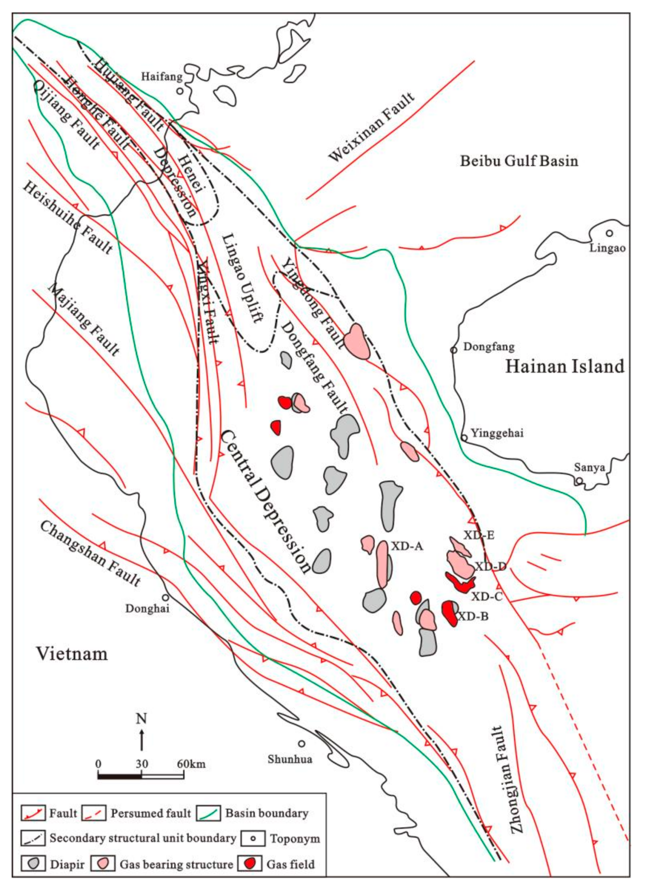
Figure 2.
Comprehensive strata log diagram of the Yinggehai Basin with the source-reservoir-cap assemblage and main tectonic event.
Figure 2.
Comprehensive strata log diagram of the Yinggehai Basin with the source-reservoir-cap assemblage and main tectonic event.

Figure 3.
Vertical distribution of gas in diapir zone and slope zone in Yinggehai Basin.

Figure 4.
Hydraulic fracture pressure for the cap rock in different stress and mechanical properties. The Mohr circles, from large to small, indicate the critical conditions of shear, extension-shear and extension fracture of intact cap rocks and fractured cap rocks, and the corresponding maximum sustainable fluid pressures are A1C1, A2C2, A3C3 and B1C1, B2C2, B3C3(modified by Sibson(1996)).

Figure 5.
(a) Classic XLOT curve in the drilling [24]; (b–d) The different types XLOT curves in study area.
Figure 5.
(a) Classic XLOT curve in the drilling [24]; (b–d) The different types XLOT curves in study area.
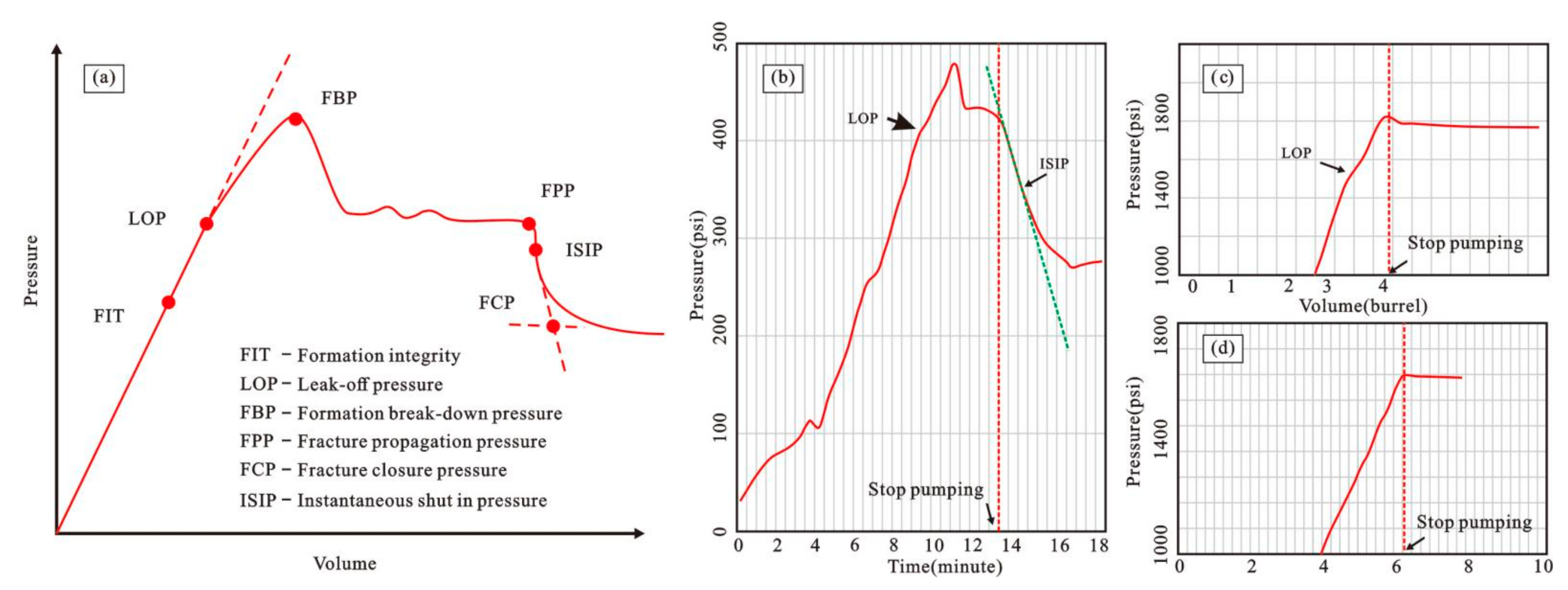
Figure 6.
(a) The density measurements of 5 Wells in the three blocks of the study area. The relationship between density and depth follows a power function. (b) Vertical principal stress obtained by the density log from the 5 wells. The vertical stress gradient is shown to increase with depth and close to 22.8 MPa/km in Huangliu Formation.

Figure 7.
Horizontal principal stress in study area. SHmax is calculated by the Hubbert–Willis equation [50] under the assumption of zero tensile strength. SHmax is interpreted from LOTs and XLOTs. The data show the characteristics of stress pressure coupling, that is, the horizontal principal stress increases with the pore fluid pressure increasing [51,52,53].
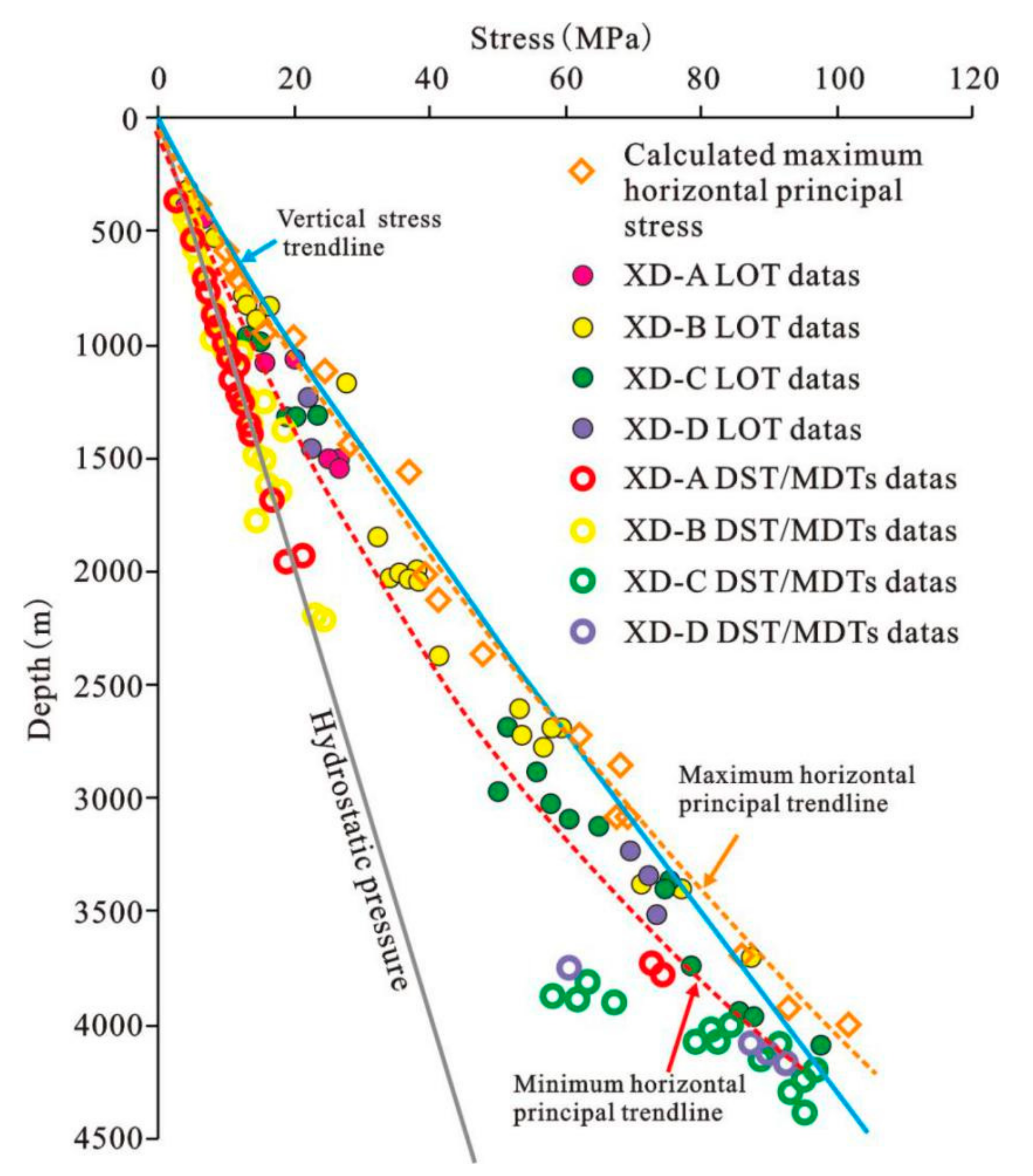
Figure 8.
Mohr diagram plotting shear stress against effective normal stress.

Figure 9.
Prediction of tensile strength from the well XD-A1. The one quarter of the differential stress is always less than the tensile strength in the whole depth, it means that extensional fracture always occurs for the intact cap rock.
Figure 9.
Prediction of tensile strength from the well XD-A1. The one quarter of the differential stress is always less than the tensile strength in the whole depth, it means that extensional fracture always occurs for the intact cap rock.

Figure 10.
Hydraulic fracture risk of Huangliu Formation in the present stress and pressure condition.
Figure 10.
Hydraulic fracture risk of Huangliu Formation in the present stress and pressure condition.
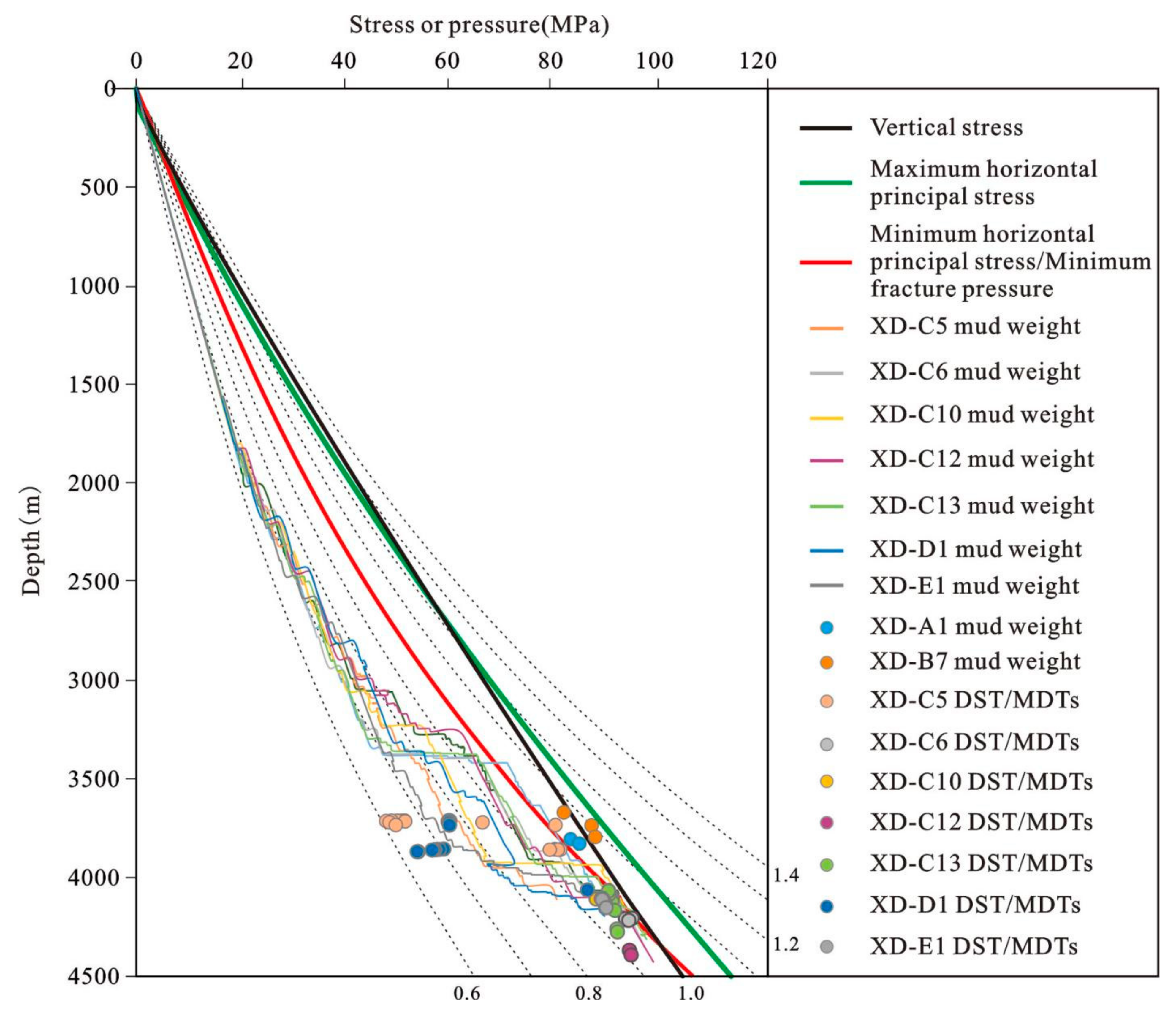
Figure 11.
Burial history of the five blocks in study area and the hydraulic risk analysis of Huangliu and Meishan Formation in geological time. (a–c) is the XD-A, the palaeopressure was larger than the hydraulic, indicating continuous leakage in whole geological time in both Huangliu and Meishan Formation. The Xd-B show in (d–f) is similar to the XD-A, the leakage time was later than XD-A, and still leaking today. (g–i) and (j–l) is present XD-C and XD-D block, hydraulic fracture occurred about 2 Ma. (m–o) is the XD-E which is farthest from the diapir, has not reached the hydraulic fracture pressure in the historical period until now.

Table 1.
The fracture mode and criterion of rocks in different differential stress [26].
Table 1.
The fracture mode and criterion of rocks in different differential stress [26].
| Fracture Mode | Fracture Criterion | Differential Stress Condition |
|---|---|---|
| Extensional fracture | P = S3 + T | S1 − S3 < 4T |
| Extensional shear fracture | P = Sn + (4T2 − τ2)/4T | 4T < S1 − S3 < 6T |
| Shear fracture | P = Sn + (C − τ)/μ | S1 − S3 > 6T |
Publisher’s Note: MDPI stays neutral with regard to jurisdictional claims in published maps and institutional affiliations. |
© 2021 by the authors. Licensee MDPI, Basel, Switzerland. This article is an open access article distributed under the terms and conditions of the Creative Commons Attribution (CC BY) license (https://creativecommons.org/licenses/by/4.0/).
Share and Cite
MDPI and ACS Style
Jia, R.; Fan, C.; Liu, B.; Fu, X.; Jin, Y. Analysis of Natural Hydraulic Fracture Risk of Mudstone Cap Rocks in XD Block of Central Depression in Yinggehai Basin, South China Sea. Energies 2021, 14, 4085. https://doi.org/10.3390/en14144085
AMA Style
Jia R, Fan C, Liu B, Fu X, Jin Y. Analysis of Natural Hydraulic Fracture Risk of Mudstone Cap Rocks in XD Block of Central Depression in Yinggehai Basin, South China Sea. Energies. 2021; 14(14):4085. https://doi.org/10.3390/en14144085
Chicago/Turabian StyleJia, Ru, Caiwei Fan, Bo Liu, Xiaofei Fu, and Yejun Jin. 2021. "Analysis of Natural Hydraulic Fracture Risk of Mudstone Cap Rocks in XD Block of Central Depression in Yinggehai Basin, South China Sea" Energies 14, no. 14: 4085. https://doi.org/10.3390/en14144085
Note that from the first issue of 2016, this journal uses article numbers instead of page numbers. See further details here.