Numerical and Experimental Study of Air-to-Air Plate Heat Exchangers with Plain and Offset Strip Fin Shapes


1
LG Electronics, 170, Seongsanpaechong-ro, Changwon-si, Gyeongsangnam-do 51533, Korea
2
Ecoenergy Research Institute, 2323 Daejeo-dong, Kangseo-gu, Busan 46703, Korea
3
School of Mechanical Engineering, Pusan National University, Busan 46241, Korea
4
Research Institute for Future Wind Energy Technology, Pusan National University, Busan 46241, Korea
5
School of Architectural Engineering, Pusan National University, Busan 46241, Korea
*
Author to whom correspondence should be addressed.
Energies 2020, 13(21), 5710; https://doi.org/10.3390/en13215710
Submission received: 2 August 2020
/
Revised: 25 October 2020
/
Accepted: 26 October 2020
/
Published: 31 October 2020
(This article belongs to the Special Issue Experimental Heat Transfer in Energy Systems)
Abstract
:This study evaluates the performance of a plate heat exchanger numerically and experimentally. The predictive model for estimating the heat transfer and frictional pressure drop across the plain and offset strip fins is compared with the experimental results with the parameters of Reynolds number and fin pitch. The heat transfer of the offset fin shape is 13.4% higher than that of the plain fin in the experiment in the case of Re = 6112 for the hot airflow and Re = 2257 for the cold airflow. A predictive model uses the effectiveness-Number of Transfer Units (NTU) method with the discretization in the segments divided into small control volumes in the heat exchanger. The difference of heat transfer and pressure drop for the plain fin between the numerical and the experimental results are approximately 1.9% and 5.9%, respectively. Thus, the results indicate that the predictive model for estimating the heat transfer is useful for evaluating the performance of the plate heat exchanger in the laminar-to-transition regions.
1. Introduction
Due to their high efficiency and compactness, compared with other heat exchangers, the plate-fin heat exchanger (PFHE) is commonly used in various applications such as home appliances, electronic cooling devices, air-conditioning evaporators and condensers, chemical industries, cryogenics for separation, the production of petrochemicals, and aerospace. PFHEs are characterized by the large ratio of surface area by volume, which usually consists of an array of plate fins that are rectangular, offset strip, triangular, perforated, wavy, or louvered [1]. The main advantages of PFHE are large heat transfer area, excellent heat transfer effect, light and compact design, low contamination rate inside the plate heat exchanger, less space than shell tube type, and heat exchange between multiple streams. Various kinds of plate-fin channels, based on different applications, also employ special techniques to enhance heat transfer [2]. Air-to-air plate heat exchangers are a very effective and inexpensive means for heating or cooling fluids in electronic cooling devices and air-conditioning systems. Air-to-air heat exchangers with offset fin shapes have a number of advantages, such as high efficiency, compact structure, high mechanical strength, easy maintenance, or capacity adaptability. Optimal design plays an important role in improving heat transfer and reducing the pressure drop.
Many researchers have worked on the heat transfer and friction factors of the plate heat exchanger with the design parameter of the plate-fin heat exchanger such as fluid type, laminar/transitional/turbulent flow regime, fin shapes for hot/cold fluids, and fin pitch. There is no unique solution or method to evaluate the performance of the heat transfer and friction factors of the plate-fin heat exchanger. Khoshvaght-Aliabadi et al. [2] conducted experimental works for evaluating the performance of PFHE with various plate-fin shapes. They have found that the vortex-generator has the significant increase of the heat transfer. Mortean and Mantelli [3] suggested new correlation for estimating the Nusselt number correlations of the plate heat exchanger in transitional flow regimes with the good agreement between the experimental and numerical results. Churchill [4] suggested friction-factor equation as a function of Reynolds number, surface roughness, and pipe diameter and provided unique values for all fluid flow regimes. Zheng and Qi [5] reviewed various offset strip fins for gas and liquid fluids including two-phase flow numerically and experimentally. Brenk et al. [6] conducted research on the development of efficient and fast numerical methodologies related to the plate heat exchanger research. Additionally, geometric optimization was performed to improve PFHE performance by improving maldistribution. Peng et al. [7] presented a new inlet header configuration with splitter plates for plate-fin heat exchanger which can decrease the flow maldistribution and pressure drop simultaneously. Manglik and Bergles [8] studied the correlations to evaluate the performance for the plate heat exchanger with rectangular offset strip fin and proposed the design tools to predict the heat transfer and friction factor. In addition, Joshi and Webb [9] presented the empirical correlations to predict the characteristics of heat transfer and friction in the offset strip fin heat exchanger numerically and experimentally. Hu and Herodi [10] described the effect of the Prandtl to estimate the heat transfer and pressure drop in offset fin shapes and proposed the predictive model for heat transfer and pressure drop. Vyas and Agrawap [11] reviewed research on heat transfer in offset strip fin heat exchangers and described the broad discussion on 2D and 3D offset strip fins studied numerically and experimentally.
In this study, we undertake the numerical and experimental works for the performance evaluation of the heat transfer and frictional pressure drop between the plate heat exchanger for condensing the moisture from the humid and hot air in a household dishwasher. Using the correlation equations of heat transfer and pressure drop previously studied, we intend to optimally design the PFHE through the comparative analysis between the model and the experimental results. We study the combination of the array of plain and offset strip fins of the PFHE as a function of fin pitch. The finite volume method (FVM) along with the effectiveness-NTU and the discretization in the segments divided into small control volumes in the heat exchanger is used to predict the heat transfer rate of the plate fin heat exchanger. The predictive model for estimating the heat transfer and friction factor across the plate fin heat exchanger are compared to the experimental results. The test conditions include cold airflow, representing the laminar and transition regimes, and hot airflow, representing the transition regime.
2. Experimental Methods
2.1. Air-to-Air Plate Heat Exchanger
Figure 1 represents a schematic diagram of the plate heat exchanger for condensing the moisture from the humid and hot air in a household dishwasher, as used in this study. The heat inside the dishwasher improves drying by water evaporation from the dish and reducing the surface tension of the water. The humid, hot air evaporated from the dishes moves to the plate heat exchanger to condense the moisture. The removal of moisture from the dishes in a dishwasher is an important parameter for improving the performance of the dishwasher in cleaning dishware and cutlery automatically.
Dried air coming out from the plate heat exchanger is not expelled to the outside but it is returned to the dishwasher tub. Household dishwashers are usually cleaned by spraying hot water in the range of 40–75 °C. Moisture removal methods in commercial dishwashers include dehumidification at the wall inside the dishwasher, discharge of the moisture outside the dishwasher, and application of an adsorbent. However, the PFHE is more hygienic and does not require discharging moisture outside the dishwasher. In this study, the evaluation performance of the plate heat exchanger for condensing the moisture in the dishwasher is analyzed using the predictive model and experimental work.
Figure 2 represents the PFHE drawing with a description of the hot and cold airflow directions. The heat exchanger is made from aluminum alloy 3003. The cross-flow arrangement of hot air and cold air offers superior heat transfer performance and a more convenient mechanical layout to remove the moisture from the dishwasher. The cold airflow consists of two streams, one on the top and one on the bottom, with the rectangular plain or offset fin shapes. At the same time, the hot humid air flows into an open-air channel to remove the moisture evaporated from the dishes.
The hot air flows inside each channel along the horizontal direction without any mixing between the channels. Heat transfers from the hot air stream through the contact to the fin wall and from the fin wall to the cold air. In this study, proposed empirical correlations for evaluating the performance of the PFHE compares with the experimental results with the parameters of Reynolds number and fin pitch.
Figure 3 shows a drawing of the plain and offset strip fins in the plate-fin heat exchanger installed on the cold airflow side. PFHE design includes many geometric and operating parameters, such as channel length, channel height, temperatures, airflow rate, fin height, fin thickness, fin pitch, and fin length. In general, plain fins have the performance of lower heat transfer and pressure drop compared with offset fins. Additionally, the offset fin provides heat transfer coefficients that are 2–3 times higher than that offered in plain fin shape with the same fin pitch [12].
2.2. Experimental Apparatus for Evaluating the Plate Heat Exchanger
Figure 4 represents the schematic diagram used for evaluating the performance of the plate heat exchanger with plain and offset strip fins. The experimental apparatus consists of two fans (Inno Tech TB-6B), an electric heater, pressure sensors (Sensirion SDP 610, ±3% of reading), temperature and humidity sensors (Sensirion SHT75, ±0.3 °C, ±1.8%RH), T-type thermocouples and data loggers (Agilent 34970A, ±1 °C) with every 2 s sampling time, power meters (Yokogawa WT310, ±0.1% of reading), two straighteners for uniform flow distribution, and the plate heat exchanger. Parts are connected by insulating ducts.
Fans are calibrated by the fan tester certified by AMCA standard 210 and ASHRAE standard 51. The experimental data of temperature and pressure drop is acquired after 10 min, which is a stable flow state in the heat exchanger. Due to the characteristics of the orthogonal heat exchanger, a temperature difference occurs depending on the location of the discharge part, but the temperature is measured at five locations each, a total of 20 locations, at the inlet and outlet of the heat exchanger on the hot air side and the cold air side and the heat exchange amount using the average temperature of 10 min is calculated. The heat transfer rate can be determined with the data of air flow rate, specific heat, and the difference of the inlet and outlet temperature.
The cooling fan forces cooling air from the surroundings to the cold side of the air-to-air heat exchanger and the surrounding air temperature maintains at the 23 °C and 50% relative humidity (RH) by the constant temperature and humidity chamber. The fan is used to generate hot air, creating a hot air stream with an open loop. Both the cool and hot airflow rates are controlled between 0.4 and 0.8 m3/minute (CMM), with the cold-air-flow test conditions representing the laminar and transition regimes and the hot air representing the transition regime.
Table 1 lists the physical parameters and test conditions to evaluate the performance of the plate heat exchanger. For the hot air, the temperature and relative humidity are 75 °C and 3.6% RH, respectively, while the temperature and relative humidity are 23 °C and 50% RH, respectively, for the cold air. The proposed empirical correlations for predicting the Nusselt number and pressure drop across the PFHE are compared with the experimental results with the parameters of Reynolds number and fin pitch. The fin pitches used for the cold air channel are 3.5 and 5.3 mm in this study. The Reynolds number of the cold airflow ranges from 1115 to 2686, representing the laminar regime and transition regime. For the hot airflow, the Reynolds number ranges from 3056 to 6112, representing the transition regime. In the PFHE design in this study, the channel lengths of the hot and cold air are 200 and 205 mm, respectively, while the channel heights of the hot and cold air are 7.9 and 3.8 mm, respectively.
3. Numerical Methods
The finite volume method (FVM) is used to predict the performance of the plate heat exchanger in terms of heat transfer rate, with the mini-channels and segments divided into small control volumes. The plate heat exchanger is divided into several segments along the channel. In each segment, mass and energy conservation equations are applied. This method is generally very useful, especially for determining the heat transfer rate and the outlet temperatures of the hot and cold air in the plate heat exchanger with the given conditions of the inlet temperatures of the hot and cold air.
Figure 5 presents a schematic of the discretization in the segments divided into small control volumes in the heat exchanger for predicting the heat transfer rate and pressure drop across the PFHE using the effectiveness-NTU method in this study. The heat exchanger is discretized into five mini-channels along the X-direction of the cold airflow in a number of segments, consisting of two top and bottom flow streams which the first channel consists from segment 1 to segment 5, the second channel from segment 6 to segment 10, and so on. In addition, the hot airflow along the Y-direction could be described in a number of segments with center flows which the first channel consists of from segment 1 to segments 6, 11, 16, and 21; the second channel from segment 2 to segments 7, 12, 17, and 22; and so on. All segment dimensions are independent except that the air and fin have the same discretization. The equations of mass and energy conservation are determined for the 2D segments in the plate heat exchanger.
The outlet temperature and heat transfer rate of the hot and cold air in the PFHE can be determined, using the correlation between the heat transfer and the friction factor with the given conditions of the inlet temperatures of the hot and cold air. The cold air flowed inside each channel along the X-direction, with no mixing between the channels. The heat is transferred from the hot airflow to the fin tube wall through contact, as well as from the fin wall to the cool air. In this study, the assumptions are uniform inlet velocity in the cell, no heat transfer from the outer surfaces to the environment, and smooth surfaces. Heat flux varies depending on the flow cross section of the heat exchanger. To take this into account in this study, the heat exchanger is divided into 25 segments and the heat flux for each part is calculated. The amount of heat exchange assuming that the heat flux is constant within the same segment can be determined.
The prediction model to determine the heat transfer rate of the PFHE using the discretization method in segments divided into small control volumes in the heat exchanger and the effectiveness-NTU method can be described in the following steps: (1) the Reynolds number and the Prandtl number in the segment 1 located in the first channel can be calculated by the given input data such as the geometry of the PFHE, the inlet temperature, relative humidity, and air flow rate of the cold and hot air flows in Table 1. (2) The Nusselt number (Nu) can be calculated using the correlation provided by Gnielinski [13] for the plain fin and Manglik and Bergles [8] for the offset fin in Table 2. (3) The coefficient of overall heat transfer (U) in the segment 1 described in Equation (16) in Table 3 can be determined using the Nusselt number obtained in the previous step. Details are elaborated in the paragraph explaining Table 3. (4) The heat transfer rate (Q) in the segment 1 can be determined using the effectiveness-NTU method in Equation (10a) in Table 3. (5) The outlet temperature and relative humidity in the segment 1 can be determined using the heat transfer rate in the Equation (10b) in Table 3. (6) In the next segment 2, the heat transfer rate, outlet temperature, and relative humidity can be determined using the above five steps and using the outlet temperature and relative humidity in the segment 1 provided by step 5 as inlet conditions of the segment 2. (7) The heat transfer rate in the first channel can be obtained by adding up from segment 1 to segment 5, and the total heat transfer rate in the heat exchanger can be determined by adding up from channel 1 to channel 5.
The prediction model to determine the pressure drop across the PFHE can be calculated using the Darcy–Weisbach equation and the friction factor correlation, provided by Churchill [6] for the plain fin and Manglik and Bergles [8] for the offset fin in Table 2. The pressure drop across the PFHE can be determined by adding up and averaging from channel 1 to channel 5.
Table 2 lists the correlations between the heat transfer and the friction factor for predicting the plate-fin heat exchanger. To predict the PFHE’s thermal performance in Table 2, the Nusselt number correlation, provided by Gnielinski [13], for hot airflow in a transition regime and cold airflow with plain fins is applied. Gnielinski [13] summarized the correlation equations for predicting the heat transfer in hydrodynamics and the thermal development of flow. For the offset fins, the Nusselt number and pressure drop correlations provided by Manglik and Bergles [8], can be applied. The correlations for the friction factors from Churchill’s work [6] for predicting pressure drop across the plain-fin PFHE are derived in this study, as shown in Table 2.
Pressure drop across the plate-fin heat exchanger can be calculated by Equations (4) and (5) described the friction factor. Churchill [6] found a single correlating equation for friction loss determined with the parameters of the Reynolds number and surface roughness. A model proposed by Manglik and Bergles [8] is used for the offset strip fin shape in the cold airflow of the laminar-to-transition regime.
Table 3 describes the equations used to calculate the heat transfer rate in the plate heat exchanger using the effectiveness-NTU method [14]. The log mean temperature difference (LMTD) method is very useful for determining the heat transfer rates and the outlet temperature of both hot and cold air. The heat transfer rate in the plate heat exchanger can be determined in Equation (10a). The maximum possible heat transfer rate in Equation (11) can be determined from the smaller heat capacity and the maximum temperature difference in the heat exchanger. Therefore, the maximum possible heat transfer rate can be calculated from the inlet temperatures of the hot and cold air and their mass flow rates. The relations of the heat transfer effectiveness in Equations (12) and (13) can be described as the dimensionless group NTU and the heat capacity ratio [14]. Therefore, the heat transfer effectiveness can be used to determine the heat transfer rate without knowing the outlet temperatures of airflows. The NTU in Equation (15) can be derived by the coefficient of total heat transfer in the plate heat exchanger and the smaller heat capacity ratio.
4. Results and Discussion
Figure 6 compares the experimental and numerical heat transfer of the plate heat exchanger as a function of the Reynolds number of the cold airflow rate. The amount of heat transfer has been found to increase in relation to increasing the hot airflow rate and in relation to an increasing Reynolds number of the cold airflow rate. In addition, the heat transfer of the offset fin shape is higher than that of the rectangular plain fin shapes. In the case of Re = 6112 for the hot airflow and Re = 2257 for the cold airflow, the heat transfer of the offset fin shape is 13.4% higher than that of the plain fin in the experiment, as shown in Figure 6c. In addition, the Nusselt numbers of the offset fins and plain fins provided by Gnielinski [13] and Manglik et al. [8] are 15.9 and 7, respectively, meaning the Nusselt number of the offset fins is 2.3 times higher than that of the plain fins having the same fin pitch of 3.5 mm.
The segment distribution of outlet temperature on the hot airflow of segments 21–25 ranges from 56.6 to 65.8 °C and for the cold airflow of segments 5–25 ranges from 38.4 to 32.5 °C. The offset strip fin significantly enhances the heat transfer due to the repetitive growth of the laminar boundary layer, which can then dissipate in the wake region [15]. For the range of Reynolds numbers studied for the cold airflow, the predictive model has a good agreement with the experimental results.
Figure 7 compares the experimental and numerical heat transfer of the plate heat exchanger at the 3.5 and 5.3 mm fin pitches. The amount of heat transfer increases in relation to an increasing hot airflow rate and in relation to an increasing Reynolds number of the cold airflow rate. In the case of Re = 6112 for the hot airflow and Re = 2257 for the cold airflow, the heat transfer of the 3.5 mm fin pitch in the plain fin shape is 9.3% higher than that of the 5.3 mm fin pitch, as shown in Figure 7c. It is believed that a smaller fin pitch could use more fins and a greater heat transfer area, thus enhancing the heat transfer. In addition, the Nusselt number of the 3.5 and 5.3 mm fin pitches provided by Gnielinski [13] and Manglik et al. [8] are 7 and 7.5, respectively. Similarly, the predictive model has a good agreement with the experimental results for the range of Reynolds numbers of the cold airflow studied here.
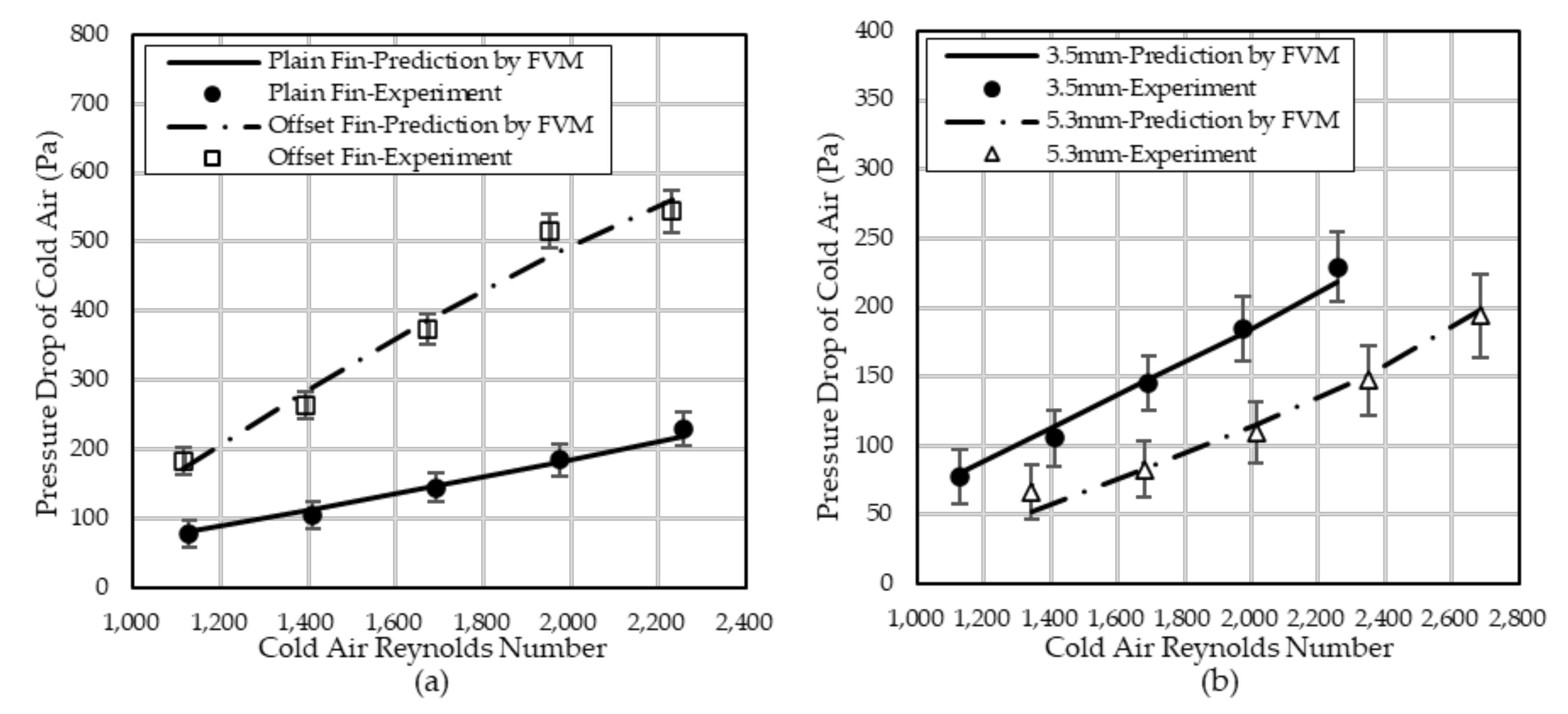
Figure 8 compares the experimental and predictive pressure drop across the air-to-air plate heat exchanger as a function of the Reynolds number of the cold air, showing (a) the plain and offset strip fins, and (b) the fin pitch. The pressure drop across the PFHE plays an important role in heat exchanger design; for both fins, the pressure drop increases in relation to increasing cold airflow rate, similar to the results regarding heat transfer. The offset fin provides pressure drop values two times higher than that provided by plain fin geometry with the same fin pitch of 3.5 mm. The pressure drop is 255% higher at Re = 2257 for the cold airflow in Figure 8a. The offset strip fin significantly increases the pressure drop due to the repetitive growth of the laminar boundary layer, which can then dissipate in the wake region [15]. The pressure drop across the fin channel at a 3.5 mm fin pitch is 50% higher than that at a 5.3 mm fin pitch at the Re = 2257 for the cold airflow as shown in Figure 8b. It is believed that the smaller fin pitch used more fins and a greater fin area, thus increasing the pressure drop across the heat exchanger.
Figure 9 shows the difference comparison of the numerical and experimental heat transfer of the plate heat exchanger. For the studied range of Reynolds numbers for the cold airflow, the predictive model has a good agreement with the experimental results for the plain fin shape, with a difference of approximately 1.9% between the numerical and experimental results. Therefore, the correlation for predicting the heat transfer is useful for compact PFHEs operating under similar conditions of in the laminar-to-transitional flow region to those tested in this study. The difference comparison of the numerical and experimental pressure drop across the plate heat exchanger is shown in Figure 10. For the studied range of Reynolds numbers for the cold airflow, the numerical and experimental results demonstrate similar results, with an approximately 5.9% difference between the numerical and experimental results.
5. Conclusions
The performance of the heat transfer and pressure drop across the plate heat exchangers with plain rectangular and offset strip fin shapes was evaluated using the predictive models and experimental study. The predictive model compares the experimental results with the parameters of Reynolds number and fin pitch. In this study, the cold airflow represents the laminar or transition regime, and the hot airflow represents the transition regime. The amount of heat transfer increases in relation to an increasing hot airflow rate and in relation to an increasing Reynolds number of the cold airflow rate. In addition, the heat transfer of the offset fin shape is higher than that of the plain rectangular fin shape. In the case of Re = 6112 for the hot airflow and Re = 2257 for the cold airflow, the heat transfer of the offset fin shape is 13.4% higher than that of the plain fin in the experiment. A predictive model uses the effectiveness-NTU method with the discretization in the segments divided into small control volumes in the heat exchanger. The difference of heat transfer and pressure drop for the plain fin between the numerical and the experimental results are approximately 1.9% and 5.9%, respectively.
Author Contributions
Conceptualization, K.R.K.; Data curation, K.R.K., Y.C.A.; Formal analysis, H.D.J. and Y.C.A.; Investigation, J.K.L. and Y.H.K.; Resources, J.K.L. and Y.H.K.; Validation, K.R.K. and J.K.L.; Writing—original draft, K.R.K.; Writing—review and editing, H.D.J. and Y.C.A. All authors have read and agreed to the published version of the manuscript.
Funding
This study was financially provided by the National Research Foundation of Korea (NRF) grant and the Korea government (MSIT) (No. 2018R1A2B6004137).
Conflicts of Interest
The authors declare no conflict of interest.
Nomenclature
| Flat-plate heat transfer area | |
| Fin area of heat transfer | |
| Flat-plate heat transfer area (except for fin contact area) | |
| Fin area of heat transfer in the heat exchange | |
| Cross-sectional area | |
| Height of rectangular | |
| Width of rectangular | |
| The larger heat capacity | |
| The Smaller heat capacity | |
| Capacity ratio | |
| Specific heat | |
| Hydraulic diameter | |
| Maximum difference between prediction and experiment | |
| Mean difference between prediction and experiment | |
| Friction factor | |
| Channel height | |
| Coefficient of convection heat transfer | |
| Colburn j factor | |
| Thermal conductivity | |
| Flow path length | |
| Single offset fin length | |
| Mass flow rate | |
| Number of transfer unit | |
| Nusselt number | |
| Prandtl number | |
| Pressure | |
| Wetted perimeter | |
| Heat transfer rate | |
| Maximum possible heat transfer rate | |
| Roughness | |
| Reynolds number | |
| Relative humidity | |
| Fin pitch | |
| Temperature | |
| Air inlet temperature | |
| Air outlet temperature | |
| Fin thickness | |
| Overall heat transfer coefficient | |
| Arbitrary parameter, | |
| Location in the flow path | |
| Arbitrary parameter, | |
| Ratio, | |
| Ratio, | |
| Intermittency factor | |
| ∆ | Pressure drop |
| Heat exchanger plate thickness | |
| Heat transfer effectiveness | |
| Fin efficiency | |
| Air dynamic viscosity | |
| Face velocity | |
| Friction factor of smooth pipes for turbulent flow | |
| Air density | |
| Ratio, | |
| c | Cold air |
| h | Hot air |
References
- Anish, A.; Raj, B.A.; Thirumalai, T.R. A Review on Plate Fin Heat Exchanger. Int. J. Mech. Eng. 2017, 4, 33–47. [Google Scholar]
- Khoshvaght-Aliabadi, M.; Hormozi, F.; Zamzamian, A. Role of Channel Shape on Performance of Plate-fin Heat Exchanger: Experimental Assessment. Int. J. Therm. Sci. 2014, 79, 183–193. [Google Scholar] [CrossRef]
- Mortean, M.V.V.; Mantelli, M.B.H. Nusselt Number Correlation for Compact Heat Exchangers in Transition Regimes. Appl. Therm. Eng. 2019, 151, 514–522. [Google Scholar] [CrossRef]
- Churchill, S.W. Friction Factor Equation Spans All Fluid Flow Regimes. Chem. Eng. 1977, 84, 91–92. [Google Scholar]
- Zheng, X.; Qi, Z. A Comprehensive Review of Offset Strip and its Application. Appl. Therm. Eng. 2018, 139, 61–75. [Google Scholar] [CrossRef]
- Brenk, A.; Pluszka, P.; Malecha, Z. Numerical Study of Flow Maldistribution in Multi-Plate Heat Exchangers Based on Robust 2D Model. Energies 2018, 11, 3121. [Google Scholar] [CrossRef] [Green Version]
- Peng, X.; Li, D.; Li, J.; Jiang, S.; Gao, Q. Improvement of Flow Distribution by New Inlet Header Configuration with Splitter Plates for Plate-Fin Heat Exchanger. Energies 2020, 13, 1323. [Google Scholar] [CrossRef] [Green Version]
- Manglik, R.M.; Bergles, A.E. Heat Transfer and Pressure Drop Correlations for the Rectangular Offset Strip Fin Compact Heat Exchanger. Exp. Therm. Fluid Sci. 1995, 10, 171–180. [Google Scholar] [CrossRef]
- Joshi, H.M.; Webb, R.L. Heat Transfer and Friction in Offset Strip Fin Heat Exchanger. Int. J. Heat Mass Transf. 1987, 30, 69–80. [Google Scholar] [CrossRef]
- Hu, S.; Heroldi, K.E. Prandtl Number Effect on Offset Fin Heat Exchanger Performance: Predictive Model for Heat Transfer and Pressure Drop. Int. J. Heat Mass Transf. 1995, 38, 1043–1051. [Google Scholar] [CrossRef]
- Vyas, A.; Agrawap, A.B. Offset-Strip Fin Heat Exchangers a Conceptual Review Study. Int. J. Eng. Res. Appl. (IJERA) 2013, 3, 1306–1312. [Google Scholar]
- Dewatwal, J. Design of Compact Plate Fin Heat Exchanger. Bachelor’s Thesis, Department of Mechanical Engineering, National Institute of Technology, Rourkela, India, 2009. [Google Scholar]
- Gnielinski, V. G1 Heat Transfer in Pipe Flow. In VDI Heat Atlas, 2nd ed.; Springer: Berlin/Heidelberg, Germany, 2010; pp. 691–700. ISBN 978-3540778776. [Google Scholar]
- Cengel, Y.A.; Ghajar, A.J. Heat and Mass Transfer: Fundamentals & Applications, 5th ed.; McGraw-Hill Education: New York, NY, USA, 2011; ISBN 978-0073398187. [Google Scholar]
- Coletti, F.; Hewitt, G.F. Heat Exchanger Design Handbook, Multimedia ed.; Begell House: Danbury, CT, USA, 2020; ISBN 978-1-56700-423-6. [Google Scholar]
Figure 1.
Schematic diagram of the plate-fin heat exchanger for condensing the moisture from the humid hot air in the household dishwasher used in this study.
Figure 1.
Schematic diagram of the plate-fin heat exchanger for condensing the moisture from the humid hot air in the household dishwasher used in this study.

Figure 2.
Structure of the plate-fin heat exchanger, showing the airflow direction (Lc, channel length for cold air; Lh, channel length for hot air; Hc, channel height for cold air; Hh, channel height for hot air).
Figure 2.
Structure of the plate-fin heat exchanger, showing the airflow direction (Lc, channel length for cold air; Lh, channel length for hot air; Hc, channel height for cold air; Hh, channel height for hot air).

Figure 3.
Drawing of rectangular plain and offset strip fins in the air-to-air plate heat exchanger for cold airflow, (a) rectangular plain fin shape; (b) offset fin shape; (c) geometry of offset fin (Lo, single offset fin length of cold air channel; t, fin thickness; s, length of fin pitch; Hc, height of cold air channel).

Figure 4.
Schematic diagram for measuring the performance of air temperature, airflow rate, and pressure drop of the plate-fin heat exchanger.
Figure 4.
Schematic diagram for measuring the performance of air temperature, airflow rate, and pressure drop of the plate-fin heat exchanger.

Figure 5.
Schematic of the discretization in the segments divided into small control volumes for predicting the heat transfer rate and pressure drop across the plate-fin heat exchanger.
Figure 5.
Schematic of the discretization in the segments divided into small control volumes for predicting the heat transfer rate and pressure drop across the plate-fin heat exchanger.

Figure 6.
Experimental and numerical comparison of heat transfer in the plate-fin heat exchanger at 3.5 mm of fin pitches as a function of cold airflow rate, (a) Re = 3056 for the hot airflow rate; (b) Re = 4584; (c) Re = 6112.
Figure 6.
Experimental and numerical comparison of heat transfer in the plate-fin heat exchanger at 3.5 mm of fin pitches as a function of cold airflow rate, (a) Re = 3056 for the hot airflow rate; (b) Re = 4584; (c) Re = 6112.

Figure 7.
Experimental and numerical comparison of heat transfer in the heat exchanger at 3.5 and 5.3 mm of plain fin pitches. (a) Re = 3056 for the hot airflow rate; (b) Re = 4584; (c) Re = 6112.
Figure 7.
Experimental and numerical comparison of heat transfer in the heat exchanger at 3.5 and 5.3 mm of plain fin pitches. (a) Re = 3056 for the hot airflow rate; (b) Re = 4584; (c) Re = 6112.

Figure 8.
Experimental and numerical comparison of the pressure drop across the plate-fin heat exchanger, (a) with plain and offset strip fins and (b) with 3.5 and 5.3 mm fin pitch.
Figure 8.
Experimental and numerical comparison of the pressure drop across the plate-fin heat exchanger, (a) with plain and offset strip fins and (b) with 3.5 and 5.3 mm fin pitch.

Figure 9.
Difference comparison of experimental and numerical results of heat transfer of the plate-fin heat exchanger (a) plain; (b) offset fin.
Figure 9.
Difference comparison of experimental and numerical results of heat transfer of the plate-fin heat exchanger (a) plain; (b) offset fin.

Figure 10.
Difference comparison of experimental and numerical results of pressure drop across the plate-fin heat exchanger (a) plain; (b) offset fin.
Figure 10.
Difference comparison of experimental and numerical results of pressure drop across the plate-fin heat exchanger (a) plain; (b) offset fin.


Table 1.
Physical parameters and test conditions for evaluating the performance of the plate heat exchanger.
Table 1.
Physical parameters and test conditions for evaluating the performance of the plate heat exchanger.
| Physical Parameters | Values | |
|---|---|---|
| Plate-fin heat exchanger geometry | Channel length for hot air, | 200 mm |
| Channel length for cold air, | 205 mm | |
| Channel height for hot air, | 7.9 mm | |
| Channel height for cold air, | 3.8 mm | |
| Fin thickness, t | 0.2 mm | |
| Fin pitch, s | 3.5, 5.3 mm | |
| Single offset fin length, | 12.8 mm | |
| Hot air test conditions | Temperature | 75 °C |
| Relative humidity | 3.6% RH | |
| Flow rate | 0.4–0.8 CMM | |
| Reynolds number | 3056–6112 | |
| Cold air test conditions | Temperature | 23 °C |
| Relative humidity | 50% RH | |
| Flow rate | 0.4–0.8 CMM | |
| Reynolds number | 1115–2686 |
Table 2.
Correlations for predicting the Nusselt number and friction factor of the heat exchanger.
| Investigators | Correlations | Equation No. | Remarks |
|---|---|---|---|
| Gnielinski [13] | Laminar regime (Re ≤ 2300) | Applied for the plain fin in the cold airflow and hot airflow. Hydraulic diameter for rectangular fin shape | |
| (1a) | |||
| ① Hydrodynamically, thermally developing | |||
| (1b) | |||
| ② Hydrodynamically developed, thermally developing | |||
| (1c) | |||
| ③ Hydrodynamically, thermally developed | |||
| (1d) | |||
| Transition regime (2300 ≤ Re ≤ 10,000) | |||
| (2a) | |||
| (2b) | |||
| Turbulent regime (10,000 ≤ Re) | |||
| (3a) | |||
| (3b) | |||
| Churchill [6] | (4) | Applied for the plain fin in the cold airflow and hot airflow | |
| (5) | |||
| Manglik and Bergles [8] | (6) | Applied for the offset fin of the cold airflow and hot airflow. | |
| (7) | |||
| (8a) | |||
| , | (8b) | ||
| (9) |
Table 3.
Equations for calculating the heat transfer rate of the PFHE using the effectiveness-NTU method [14].
Table 3.
Equations for calculating the heat transfer rate of the PFHE using the effectiveness-NTU method [14].
| Parameter | Equations | Equation No. | Remarks | |
| Heat transfer rate, | (10a) (10b) | : Heat transfer effectiveness : Maximum possible heat transfer rate | ||
| (11) | : Temperature of hot air : Temperature of cold air | |||
| Heat transfer effectiveness, | mixed, unmixed | (12) | Hot side: Mixed Cold side: Unmixed | |
| mixed, unmixed | (13) | |||
| Heat capacity ratio, c | (14) | : The smaller heat capacity : The larger heat capacity | ||
| Number of transfer units, NTU | (15) | : Mass flow rate | ||
| Coefficient of total heat transfer, U | (16) |  : Calculated from Table 2 η: Fin efficiency | ||
Publisher’s Note: MDPI stays neutral with regard to jurisdictional claims in published maps and institutional affiliations. |
© 2020 by the authors. Licensee MDPI, Basel, Switzerland. This article is an open access article distributed under the terms and conditions of the Creative Commons Attribution (CC BY) license (http://creativecommons.org/licenses/by/4.0/).
Share and Cite
MDPI and ACS Style
Kim, K.R.; Lee, J.K.; Jeong, H.D.; Kang, Y.H.; Ahn, Y.C. Numerical and Experimental Study of Air-to-Air Plate Heat Exchangers with Plain and Offset Strip Fin Shapes. Energies 2020, 13, 5710. https://doi.org/10.3390/en13215710
AMA Style
Kim KR, Lee JK, Jeong HD, Kang YH, Ahn YC. Numerical and Experimental Study of Air-to-Air Plate Heat Exchangers with Plain and Offset Strip Fin Shapes. Energies. 2020; 13(21):5710. https://doi.org/10.3390/en13215710
Chicago/Turabian StyleKim, Kyung Rae, Jae Keun Lee, Hae Do Jeong, Yul Ho Kang, and Young Chull Ahn. 2020. "Numerical and Experimental Study of Air-to-Air Plate Heat Exchangers with Plain and Offset Strip Fin Shapes" Energies 13, no. 21: 5710. https://doi.org/10.3390/en13215710
Note that from the first issue of 2016, this journal uses article numbers instead of page numbers. See further details here.