Abstract
A range extender (RE) is a device used in electric vehicles (EVs) to generate electricity on-board, enabling them to significantly reduce the number of required batteries and/or extend the vehicle driving range to allow occasional long trips. In the present work, an efficiency-oriented RE based on a small motorcycle engine modified to the efficient over-expanded cycle, was analyzed, tested and simulated in a driving cycle. The RE was developed to have two points of operation, ECO: 3000 rpm, very high efficiency with only 15 kW; and BOOST: 7000 rpm with 35 kW. While the ECO strategy was a straightforward development for the over-expansion concept (less trapped air and a much higher compression ratio) the BOOST strategy was more complicated to implement and involved the need for throttle operation. Initially the concepts were evaluated in an in-house model and AVL Boost® (AVL List Gmbh, Graz, Austria), and proved feasible. Then, a BMW K75 engine was altered and tested on a brake dynamometer. The running engine proved the initial concept, by improving the efficiency for the ECO condition in almost 40% in relation to the stock engine and getting well over the required BOOST power, getting to 35 kW, while keeping an efficiency similar to the stock engine at the wide open throttle (WOT). In order to protect the engine during BOOST, the mixture was enriched, while at ECO the mixture was leaned to further improve efficiency. The fixed operation configuration allows the reduction, not only of complexity and cost of the RE, but also the set point optimization for the engine and generator. When integrated as a RE into a typical European light duty vehicle, it provided a breakthrough consumption reduction relatively to existing plug-in hybrid electric vehicles (PHEVs) in the market in the charge sustaining mode. The very high efficiency of the power generation seems to compensate for the loss of efficiency due to the excess electricity production, which must be stored in the battery. The results indicate that indeed it is possible to have an efficient solution, in-line with the electric mobility sustainability paradigm, which can solve most of the shortcomings of current EVs, notably those associated with batteries (range, cost and charging time) in a sustainable way.
1. Introduction
Electric vehicles (EVs) have an enormous potential for enabling the quest for sustainable urban transportation. Battery electric vehicles (BEVs) rely solely on batteries for energy storage and thus are most affected by the still enormous unsolved issues regarding batteries [1]. Current batteries are very expensive, have a limited life, their energy density is still very low, being 17 times larger and 35 times heavier in relation to the same energy stored in petrol [2] and its charging is still long. New modes of fast and super-charging are increasingly available but they require massive electric power, from 50 to 450 kW [3] often during peak demand schedules and will be extremely expensive, both to manufacture and to use and tend to increase the battery degradation rate. This sometimes brings the running costs of electric vehicles in pair, if not more expensive, than conventional fuelled cars [4,5]. While subsidies support the competitiveness of BEVs, they still seem to fail to lead to favorable total costs of ownership (TCOs) within most vehicle segments and for a wide range of annual mileages according to some authors [6]. Some solutions have been proposed to reduce the cost of fast charging during hours of peak electricity demand such as through load shifting. Such a solution was assessed by the authors using stationary energy storage to store energy during low electricity demand periods and then supplying to the EV fast charging stations during the day [7]. Nevertheless, it seems clear that there is a need for practical solutions that may circumvent the limitations of current EV storage.
Hybridization, and particularly the implementation of the plug-in hybrid electric vehicle (PHEV) concept, is a way of reducing the reliance on bulk electric energy storage for long trips. Of course, the complexity level of a PHEV is higher than that of BEVs, so their use makes more sense in cases where large ranges are desired [1]. The added complexity of the PHEV dual powertrain surely isan issue, but it is something that many users are willing to deal with in order to minimize the real (or perceived) limitations of BEV limited range and charging times. In fact, the optimal battery capacities for PHEVs are quite low on a TCO perspective (between 4 and 6 kWh for a typical German driver with annual mileage of 15,000 km [8]). Regarding greenhouse gas emissions, higher capacity batteries are advisable, although the added weight will adversely affect the energy consumption [8].
Realistic efficiency figures of PHEV are not easily available, as the methodologies used to certify the consumption of these vehicles are often oversimplified. This is the case for the procedure currently used for the determination of fuel consumption, carbon dioxide (CO2) emissions and electric range for PHEVs in Europe; this procedure is described in the United Nations Economic Commission for Europe (UN-ECE) Regulation R101 and has been updated in 2017 with the worldwide-harmonized light-vehicle test procedure (WLTP), which implements its own driving cycle, the WLTC driving cycle (with the “C” standing for “driving Cycle”) [9,10]. It is mainly aimed at certifying the fuel consumption and CO2 emissions rather than the electric consumption of PHEVs. In this procedure, the consumption and emissions are recorded in two modes. One is the charge depleting (CD) mode, in which the use of the battery is preferred, with the engine being off or at most turning on only under very specific conditions (e.g., high power demanding). This mode is tested from the full state of charge (SoC) to the minimum SoC set for the CD mode. The vehicle is also tested under the charge sustaining mode (CS), which is the mode used when the minimum CD SoC is achieved and the engine will start ensuring most of the power so that the SoC does not drop below a certain minimum threshold.
The official fuel consumption is a weighted average between the CD and CS modes, with the weighting factor being the so-called “utility factor” (UF) [11]. The UF used in Europe is based on the driving statistics described by the SAE J2841 standard [12]. This factor is around 0.5 for a CD range around 23 km, which is roughly the WLTC cycle driving distance. If, for instance, the CD range is close to this value, and the engine never switches on during that mode, the WLTP energy (petrol) consumption and CO2 emissions will be half of the consumption recorded under CS. If the CD range is double that value, then the official consumption of the PHEV will be one quarter of its CS consumption. If the CD range is 100 km, then the UF will be around 90% and the official consumption will be only 10% of the CS consumption. This consumption/emissions figure is rather limited when the aim is to evaluate both the electrical consumption in CD mode, which is a measure of the electrical efficiency of the powertrain, and the consumption in CS mode.
Table 1 summarizes the characteristics gathered for some of the most prominent models in the market [13,14,15]. In terms of electrical efficiency, the Hyundai Ioniq Plug-In and the Toyota Prius Plug-in are two reference vehicles currently available in the European market. The Toyota model has a usable 6.4–7.0 kWh battery with a 43 km WLTP range in CD mode, corresponding to an electric consumption of 14.4 kWh/100 km or 0.94 kWh/(km·kg) on a specific basis. In CS mode the gasoline consumption is estimated to be 4.1 L/100 km or 0.27 L/(km·kg). The Ioniq numbers are quite similar, with an estimated 7.6 kWh usable battery, 52 km of WLTP range, 14.1 kWh/100 km and 4.2 L/100 km, respectively. In terms of specific consumption this yields 0.94 kWh/(km·kg) and 0.28 L/(km·g), respectively.

Table 1.
Specifications for some of the most popular plug-in hybrid electric vehicles (PHEVs) in the market.
Table 1 also presents the specifications for the VW Golf GTE and the BMW i3 REx. The latter was the only extended range electric vehicle (EREV, also called a series hybrid plug-in) available in Europe up to 2019, when it was discontinued. The 120 Ah version, with a 42.2 kWh battery (37.9 kWh usable), had a high 308 km WLTP electric range and an excellent electric efficiency of 13.2 kWh/100 km. Nevertheless, in charge sustaining mode, the fuel efficiency was very poor at 6.7 L/100 km (or 0.5 L/(km·kg) in terms of specific fuel consumption), which is likely due to the series architecture and relatively inefficient range extender engine (small motorcycle engine) and generator. The VW Golf GTE (2107–2018) is no longer in production: with an estimated 7.0 kWh usable battery and 37 km WLTP range, it displays the lowest electric efficiency of all the listed vehicles (18.9 kWh/100 km) and the second poorest fuel efficiency of the group (5.4 L/100 km or 0.36 L/(km·kg) on a specific basis).
For the electric ranges and electric consumptions recorded, a new, calculated battery capacity was derived (Capacity = consumption × range/100) and presented in Table 1. The European sale label consumption was derived from the procedure using the utility factor [11]. The value for the BMW I3 REx was outside of the utility factor curve and therefore was not calculated. Assuming that there is a full chemical reaction of the petrol hydrocarbons with air (which is an accurate assumption taking into account that the catalyst will complete the combustion of eventually unburned hydrocarbons and carbon monoxide [16]), the CO2 emissions will be proportional to the consumption. In other words, there is a fixed value of CO2 emissions per litre of petrol (2.31 kgCO2/L) according to the corresponding chemical reaction.
Now, the mechanical complexity and cost arising from the parallel hybrid plug-in vehicle architecture, which normally requires a full sized electrical and mechanical powertrain may be partially averted by using the series hybrid architecture. In this architecture the engine, also called the range extender (RE), acts solely as an electrical generator, which is not mechanically connected to the traction system, simplifying the powertrain. Since this engine is not responsible for direct traction, it may be more easily downsized than parallel hybrid engines. Therefore, using a RE could be a way to significantly extend the range of an EV without the need to have a bulky, heavy and expensive battery pack that most of the time is only partially used. The use of small range extenders in electric vehicles could greatly reduce the initial cost of the batteries and the cost of recharging, avoiding the need of costly fast-charging most of the time.
In terms of EREV sustainability, previous studies by the authors discovered that driving patterns with more than about 75% of urban driving using an efficiency-oriented RE would produce negligible CO2 emissions on a well-to-wheel life cycle analysis (LCA) [2]. Now, despite the aforementioned advantages of REs, the sales of EREVs have not been as high as expected. The Chevrolet Volt/Opel Ampera EREV was for some time the best sold PHEV for some periods, but battery electric vehicles such as the Tesla Model 3 have far surpassed its sales. In 2019 it was discontinued. The manufacturing costs, the perception of a complex and over-engineered vehicle, which would need specialized maintenance, as well as the difficulty to suitably market the advantages of PHEVs were some of the reasons advanced for its dismissal [17]. The other EREV in the market, the BMW i3 REx version was also discontinued in Europe in 2019. Despite the RE being a much simpler package (an optional 647cc 2-cylinder petrol range extender), in some countries it increased the price of the vehicle beyond 5 k€. The brand cited the gradually increasing battery capacities and availability of fast charging stations as the main reasons for discontinuing the RE [18]. Despite this trend of discontinuation of EREVs in the market, there are still defenders of the relevance of this technology for the future, such as Ford, which aims to apply it extensively on light commercial vehicles as a way of optimizing battery capacity and range [19] or Mazda, as it aims to revive its signature rotary engine as a compact low vibration RE solution [20]. The use of massive battery packs in vehicles, which only rarely need long ranges, also does not seem to make a lot of sense not only on an initial investment cost perspective but also in terms of dead weight increase. Furthermore, the intensive mining of rare earth elements required for batteries has sustainability issues on its own [21], so it seems that REs may play a role in optimizing the cost and sustainability of electrified vehicles. What might be lacking for a successful EREV is a compact, affordable and efficient RE, which may be able to simultaneously minimize the total cost of ownership and maximize sustainability on a life cycle basis. While the Chevrolet Volt had a mechanically complex powertrain with a full sized engine which even supplied mechanical power to the wheels in a limited range of conditions, the BMW i3 offered a compact but overly expensive and inefficient engine as RE.
There are two very different philosophies that seem to make sense for electric mobility:
- (a)
- As the RE should be seldom used, the main interest is for it to be as small and as light as possible, not to interfere with the already heavy EV;
- (b)
- As the RE is a part of a very efficient and sustainable vehicle (the EV), it should be designed to be as efficient as possible.
While Mazda’s rotary engine would fit in logic (a), the present study assesses logic (b) as the basis for the development of a range extender. In the philosophy for the EV is also the fact that the most critical and expensive item of the EV is the battery system. Batteries are getting ever more powerful and cheaper, but they still are substantially expensive and bulky [22,23]. Therefore, the logical solution for an affordable and rational EV is to use a small battery enabling an electric range during city driving (35 km) [24] and a small and compact RE for more prolonged driving. There are strategies that enable a substantial improvement of the engine efficiency. Over-expansion obtained through late intake valve closure (LIVC) combined with an optimal compression ratio (CR) for the intake charge admitted has proven to be quite effective with spark ignition engines being able to exceed typical diesel engine efficiency for most of the engine map [25]. Actually, a life cycle comparison of several types of RE done by the authors revealed that the over-expanded engine was the most promising in terms of energy efficiency and CO2 emissions [2].
The RE concept was popularized by the Chevrolet Volt/Opel Ampera, it was a highly demanded optional in the first, lower range versions of the BMW i3 and it is present in other niche vehicles, such as the sports car Fisker Karma [4] and the LEVC TX hackney carriage used as a low emission taxicab in London [26]. Some companies offer the RE as a standalone product as described in [27]. Examples are the Mahle’s 900cc twin cylinder RE [28] and Rheinmetall/KSPG/FEV compact and quiet horizontal axis V2 RE [29].
So far, an efficiency-oriented RE more in-line with electric mobility’s sustainability paradigm is still lacking. Following the previous LCA analysis of an over-expanded engine as RE [2], which was found to be the best option among rotary (Wankel), microturbine and Otto engine in terms of overall efficiency and emissions, the present paper presents the modeling and testing of such an engine. Bespoke thermodynamic analysis and commercial engine analysis software were used to optimize the engine parameters, namely various degrees of CR and valve timings. An existing 750cc engine was adapted to the over-expanded engine with several LIVC degrees and tested for torque, power and efficiency in two operating set points. One for maximum efficiency (ECO mode) and another one for power (BOOST mode). The concept is also assessed through the simulation under the WLTC cycle using a previously developed model for the energy assessment of vehicles during driving cycles [30].
2. Concept, Modeling Approach
In terms of efficiency, the developed RE (BMW K75) has seen its thermodynamic cycle being altered from the conventional Otto cycle to the much more efficient over-expanded cycle [31], also known as the Miller/Atkinson cycle. However, this alteration substantially reduces engine power. As the electric vehicle should have a power level compatible with driving on motorways, a power level required for driving at 120 km/h on a leveled road was set as a requirement. However, if the motorway has a steep incline (the maximum legal in Europe is 6%), the required power almost triples. To enable both driving actions, two conditions were set: a high efficiency mode (ECO, around 15 kW) when low power is required and a high power mode (BOOST, around 35 kW) when maximum power is necessary. Figure 1 illustrates this strategy under the CS mode in comparison with the conventional variable load mode of an engine-generator where the generated electricity follows closely the instantaneous electrical demand. While no excess energy is produced, under variable engine load the engine will operate in a wide range of operating conditions making it impossible to optimize efficiency. The dual mode (ECO/BOOST) enables us to maximize the efficiency in one particular operating condition (ECO) where the engine will be operating most of the time.
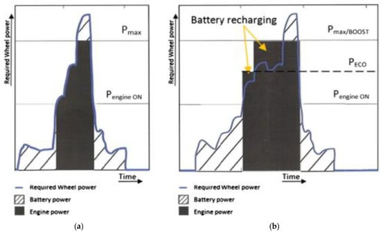
Figure 1.
Comparison between electric vehicle (EV) charge sustaining strategies with range extenders (REs): (a) variable engine load mode following instantaneous electrical demand and (b) dual power set point engine mode (ECO/BOOST) used in the present work, adapted from [2].
To enable the ECO operation, the referred BMW K75 engine had its valve closure event delayed (to allow for some backflow of the mixture, reducing the effective intake stroke) and its CR increased. The running speed (in the ECO mode) was also set to less than half of its maximum in order to minimize friction losses.
The BOOST point of operation is a strange condition: as the maximum power of a spark ignition (SI) engine occurred at maximum speed with no obstruction to the airflow to the cylinders (WOT) and since the engine CR was significantly increased, the intake was partially throttled at the BOOST condition to avoid destructive knock.
Engine simulations were performed prior to testing to assess the required cam events and CR by a specific software developed by the group [25,31] to simulate spark-ignition engines, based on the 1st Law of Thermodynamics, followed by the combustion calculations (Wiebe) [16], gas properties and gas exchange. The heat transfer (Annand) [32] and engine friction (Sandoval and Heywood) [33] were also calculated. In parallel, the commercial engine simulation software AVL Boost [34] was also used for comparison. The bespoke model allows us to have full control over the phenomena and models used, while the commercial software provides a more in-depth analysis of the engine.
The ECO and BOOST power and efficiency values that were obtained experimentally were then used in a driving cycle simulation to assess the consumption and CO2 emissions under the WLTC driving cycle for CD and CS modes. The driving cycle energy model used has been described in previous work [30]. Firstly, the instantaneous mechanical power required to fulfill the driving cycle was obtained. It accounts for the main forces acting on the vehicle, namely, aerodynamic drag, rolling resistance including tire slip and cornering force when applicable, road slope forces and inertial forces under acceleration. The next step was to predict the behaviour of the electric powertrain, battery and RE when fulfilling the cycle both under CD and CS operation. The following strategy was adopted: CD mode is active until the state of charge (SoC) dropped below 20%. Below this SoC level the CS mode was activated, with a hysteresis margin of 5%, which means that CD would be reactivated if the SoC ever recovered above 25%.
The CD operation was characterized for favouring the EV mode (mode where electricity comes from the energy storage) over the RE mode (mode where the RE is on and supplies all or part of the electric power requirement of the vehicle). Under CD operation the RE will only be active if the electric power demand overcomes the electric power supplied by the battery. A time delay for deactivation of the range extender was also set, so that if the RE is switched on, it will only switch off after a delay of 30 s, even if the electrical power can again be supplied by the battery alone. This was done in order to avoid excessive engine starts and stops.
The CS operation was characterized for favouring the use of the RE mode instead of the EV mode since under this regime the SoC of the energy storage was too low. As an exception, the EV mode would be on under CS if both the power requirement was low (below 10 kW) and the SoC was not too low (above 5%).
The RE operates under two different fixed conditions: ECO mode, in which the RE is able to supply a mechanical power of 16.4 kW with 41% thermal to mechanical efficiency; BOOST mode, in which the RE supplies s mechanical power of 36.7 kW with 32% thermal to mechanical efficiency. Whenever the RE is on, the ECO mode is favored as long as it is possible to fulfill the power demand with the power produced by the RE only or by the combination of the RE and the battery power. If the power demand overcomes the combined ECO and battery power, the BOOST mode will be activated. If the electric power production exceeds the electric power required, the excess is stored in the battery. The simulation conditions are presented in the following section.
3. Materials and Methods
3.1. Engine Test Rig
The engine is a BMW K75, 750 cm3, 3 cylinder inline, spark ignition engine connected to a 100 kW GoPower hydraulic dynamometer (Figure 2). This engine is especially suitable for adaptation to over-expansion due to its long stroke versus its bore diameter.
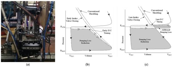
Figure 2.
(a) Engine in the test dynamometer; pumping losses for early intake valve closure (EIVC) (b) and late intake valve closure (LIVC) (c) strategies, adapted from [35].
The adaptation to the over-expanded cycle required replacing the camshafts (with different LIVC profiles) and lowering the engine block by 3.5 mm to increase the geometric CR from 10:1 to 19:1. As the engine specifications were completely changed, the stock electronic controller was not adequate and it was necessary to use a customized system. The MegaSquirt II [36], allowing a wide freedom of tuning the injection and ignition maps, was the engine control unit (ECU) used in the modified engine.
Two different strategies could be used to achieve the over expanded cycle using the intake valve opening [31]: (i) the early intake valve closure (EIVC) and (ii) the late intake valve closure (LIVC). While for the latter the intake valve opens only during a fraction of the downwards stroke, the LIVC strategy leaves the intake valve opened for the whole downwards stroke and part of the upwards stroke, therefore exhausting part of the charge already in the cylinder back to the intake manifold. According to Figure 2b,c the strategy that leads to a higher pumping loss reduction would be EIVC. However, a decision was made in favor of the LIVC strategy because, during BOOST operation, the engine would be working at a high speed (7000 rpm) and at that speed the EIVC mode would significantly reduce volumetric efficiency, and thus, the amount of air entering the cylinders. As the maximum engine speed was reduced from 8500 to 7000 rpm, the exhaust cam was also modified (its opening was extended in 10°) so that the expansion stroke would be longer than in the conventional engine, improving the over-expansion. In order to use the same pistons and avoiding the hitting of the valves on the piston crown, the intake valve opening advance and the exhaust valve closure were reduced by 10°, reducing the period (near top dead centre, TDC) when both valves were opened by 20°.
The methodology to modify the design of the intake cams was to copy the upward and downward sections of the cam and to leave the valve opened at the highest point for a certain number of degrees (of crankshaft), in what it is called “dwell”. With that intention, a simplified thermodynamic analysis was used to optimize the dwell and the compression ratio combination. Figure 3 shows one of such assessments. The higher the cam dwell, the later will the intake valve close. This will induce a smaller effective intake stroke and thus, a higher level of over-expansion, or a longer expansion ratio (ER), which is the ratio between the intake and the expansion strokes.
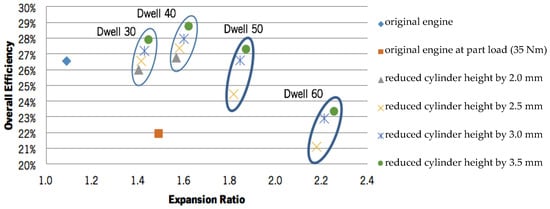
Figure 3.
Estimated engine overall efficiency for different cam dwells, compression ratio (reduction) as a function of the expansion ratio.
It is possible to perform a simplified geometric analysis to the effect of changing the intake valve closure timing and reducing the cylinder height on the trapped compression ratio and on the corresponding brake efficiency gains. Assuming that the component of the mechanical losses does not change, it is possible to correct the theoretical efficiency and indirectly the brake efficiency. This was done in a previous work [37] and is shown in Figure 3. It can be noticed that increasing the level of over-expansion first causes an increase in the efficiency for ERs up to around 1.6. This increase is associated with the rise in the expansion work provided by over-expansion. However, for ER values higher than 1.6, the overall efficiency starts falling. This excessive valve dwell causes the thermodynamic improvement obtained for the indicated engine cycle no longer compensating for the loss of net mechanical power produced with such a small effective intake stroke. Under these conditions, the low mechanical power produced starts being substantially deprecated by the mechanical losses. That is why an optimal dwell value exists for an intermediate ER value. Note that the mechanical losses of the over-expanded engine will actually be smaller than those of the original Otto cycle engine, as the piston skirt friction forces will be lower due to the shorter effective compression stroke. This is one of the reasons why the efficiency figures displayed in Figure 3 are actually under-predicted. Nonetheless, this simplified analysis allowed us to highlight the parameters at stake when altering the degree of over-expansion and the compression ratio and provided a first guess into the range of interest for the expansion ratio.
The results in Figure 3 suggest that the best combination would be to use a dwell of 40 with the highest compression ratio of the three. Unfortunately, although the model predicted that these changes would produce 15.4 kW at 3500 rpm and 36.3 kW at 7000 rpm (within the project requirements), these operating conditions would be prone to the onset of engine knock by excessive trapped compression ratio.
3.2. Engine Modifications
The optimal conditions were calculated using the thermodynamic model, but it is vital to test the engine under various conditions, so two intake camshafts were produced, one with 45° dwell and the other with 50° dwell (Figure 4a). The concept of dwell may be better understood by looking at Figure 4b, which outlines the dwell 45 cam lift compared with the original profile.
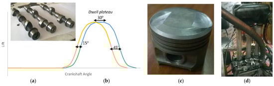
Figure 4.
(a) Inlet camshafts tested (left to right): stock, dwell 45, dwell 50; (b) outline of the dwell 45 cam profile; (c) machined piston (with 45° edge) and (d) long inlet pipes installed at intake to avoid LIVC charge backflow.
The exhaust cam was reduced by 20° (10 at opening and 10 at closure). Two extra camshafts were also manufactured and tested, with dwells of 40° and 60°. However, the camshaft with a dwell of 40° created too much knock (excessive trapped compression ratio). Furthermore, it was not possible to start the engine with the dwell 60° camshaft because the trapped compression ratio was too low, so the dwell 40° and 60° camshafts were discarded.
As the cylinder block height was cut, the piston crowns would interfere with the combustion chamber and hit the chamber walls on their sides. Therefore, the pistons were machined to avoid this interference (Figure 4c), with their top edge being cut.
As the over-expansion strategy with LIVC involved the exiting of some of the inlet charge (air-fuel mixture) from the combustion chamber after being admitted, we should make sure that it would not leak to the atmosphere. The solution was the use of long intake pipes (Figure 4d), each one with a volume of more than twice the expected volume of mixture drawn from the combustion chamber. Fortunately, this engine had three throttle plates just upstream of the inlet valves, which facilitated the conversion.
3.3. Driving Cycle Simulation Conditions
The driving cycle simulation conditions regarding vehicle, fuel and hybrid powertrain specifications, as well as the threshold levels of power and SoC for the several driving modes are presented in Table 2. The data for the vehicle and fuel used are typical for a mid-sized European vehicle. The battery and electric motor characteristics are also similar to other PHEVs in the market. The RE power and efficiency under ECO and BOOST modes are the values measured in the experimental component of the present work, presented further ahead in the results section.
Table 2.
Vehicle characteristics and modes of operation used in the driving cycle simulations.
Regarding power and SoC threshold levels, the EV mode is allowed to exist under CS operation as long as the required power is below 10 kW and the SoC is not too low (above 5%). This is typical behaviour of full hybrids and plug-in hybrids to benefit from the high efficiency of the electric powertrain under low speeds. It is also worth noting that a 5% hysteresis interval exists for the switching between the CS and CD modes so that the RE will not switch on and off too frequently. For the same reason, a minimum range extender operation time of 30 s was imposed. This means that whenever the RE is switched on it will only turn off after 30 s have passed even if it is no longer necessary. Under CS mode when the RE is operating in ECO mode, whenever the power requirement exceeds the ECO power, the battery will supply the surplus up to its maximum power. However, if the SoC is below the minimum value set for EV mode, the BOOST mode will be activated instead of using the battery.
4. Results
4.1. Engine Assessment
The engine was initially tested in stock conditions (stock inlet and exhaust camshafts and stock CR, but with the new ECU), with the fuelling map set always at stoichiometric conditions (mixture strength, λ = 1). The stock engine was tested for throttle openings ranging from 10% to 100% (WOT) (Figure 5a).
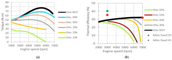
Figure 5.
(a) Measured torque as a function of engine speed, for various positions of the throttle position sensor (TPS) for the stock K75 engine and (b) comparison between experimental values of the stock (lines) and over-expanded (dots) engine efficiencies.
Subsequently, the engine was tested with both developed camshafts with CR = 19:1 and for both specified engine conditions: ECO: 3000 rpm, λ = 1.15; BOOST: 7000 rpm, λ = 0.90.
Figure 5b shows the thermal efficiency of the stock engine under some throttle conditions, with the maximum efficiency occurring for WOT, and reaching values slightly above 30%. In this figure one could also see the points of operation for the over-expanded engine using inlet camshafts with dwell 45 (green dots) and 50 (red dots), for 3000 rpm and 7000 rpm (for that speed both camshafts gave similar results). The conditions for 7000 rpm involved throttling the engine, with the throttle in a position near the 50% mark, as required to avoid engine knock. The throttle was slightly more closed for the dwell 45 camshaft, but both conditions produced matching values.
As it can be seen, for the ECO condition (3000 rpm, WOT) the engine performed much better than the stock engine, with an efficiency slightly higher than 40% for the case of the camshaft with dwell 45. We were not expecting such a good a result for the BOOST condition (7000 rpm, throttled condition), when the over-expanded engine performed, in terms of efficiency, as well as the stock engine at WOT. However, this good result can be explained. In spite of the engine being throttled, the CR of the engine was very high and the running condition was just below the onset of knock. This is the condition where the engine has better efficiency for a specific engine speed [38]. The negative effect of the pumping losses caused by the partial closure of the throttle was reversed by the higher efficiency resulting from the very high compression ratio of the engine.
On the overall, an intake camshaft with a dwell of 45° and a CR of 19:1 was selected as the proposed solution. The camshaft with a dwell of 50 yielded 15.7 kW and an efficiency of 35.4% at 3000 rpm, while the camshaft with a dwell of 45 provided 16.4 kW and an efficiency of 40.5%. These tests were performed with a lean mixture of λ = 1.15. When comparing to the stock engine also at 3000 rpm and producing similar levels of power, the throttle had to be closed between 30% and 50% and the efficiency (see Figure 5b, line for WOT) was 29%. This gave an improvement of the engine with the dwell 45 camshaft of almost 40% in terms of efficiency (fuel consumption) for that level of power. However, part of this improvement was related to the leaner conditions of the over-expanded engine. If fact, the simulations for this engine (stock) showed that the best brake specific fuel consumption (BSFC, Figure 6) would be for λ = 1.15, with an improvement of 5%.
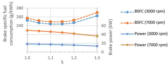
Figure 6.
Simulation results for brake specific fuel consumption and power of the stock engine as a function of mixture strength, λ.
At 7000 rpm, both camshafts provided an efficiency of 32.2% and a power of 36.7 kW, beyond the required 35 kW set at the start of the project. It should be remembered that the BOOST condition was achieved for rich (λ = 0.90) conditions, in order to prevent the engine from overheating. It is worth noting that the efficiency figures surpass the ones used in the LCA study in which the present RE concept was assessed [2]. This means that the conclusions of that study, which favors this concept, have been broadly validated.
4.2. Driving Cycle Simulation
An EREV incorporating the RE developed in the present work was simulated under the aforementioned driving cycle conditions described in UN-ECE and WLTP procedures for evaluating the official consumption of PHEVs. The simulating conditions were already displayed in Table 2. Namely, the RE power and consumption figures under the ECO and BOOST set points are the engine powers measured experimentally multiplied by the generator efficiency (see Table 2). The ECO or BOOST set point was chosen according to power required by the driving cycle. As seen further ahead, the ECO set point was always sufficient to fulfill the power requirements and therefore the BOOST set point was never activated during the simulated driving cycles.
The operation under CD mode can be observed through Figure 7a for a whole WLTC cycle. It may be seen that the RE is never tuned on as the minimum SoC for CS activation (20%) is never achieved. The electrical power needed by the motor also never exceeds the battery power, so the RE does not need to be turned on. It may be seen that the power lost in the batteries is always slightly higher than the motor requirements due to the efficiency of the battery. The regenerative braking events are also clearly seen as negative values. To estimate the CD range, the WLTC was repeated sequentially with the CS mode being only achieved at the beginning of the third consecutive WLTC cycle, for a distance around 53 km.
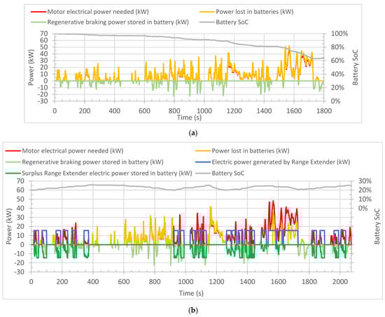
Figure 7.
Power parameters and state-of-charge for (a) charge depleting starting from full charge, under a single WLTC cycle and (b) charge sustaining starting from 20% state of charge (SoC) under an extended WLTC cycle (25 km).
Figure 7b displays the results for CS mode, which is activated when the SoC drops below 20%. This mode was ran for an extended WLTC cycle, for 25 km, as it is the distance that is used to derive the official consumption and emissions in Europe [9,10,11,12]. It can be seen that the RE operated during limited periods with a constant power corresponding to the ECO setting. The power surplus produced may be seen in dark green as a negative value. The SoC oscillated between 20% and 25%, where the EV mode is reactivated. In addition, it may be seen that whenever the ECO power is not sufficient for the power demand, the batteries supply the remainder. Therefore, the BOOST power was never required, which is good, as its consumption and emissions are substantially worse than in the case of the ECO setting.
Some results from these simulations are also summarized in Table 3. Regarding the CD results it is worth highlighting that in terms of electric consumption the value obtained (14.3 kWh/100 km) ranks between the values reported for the Hyundai Ioniq and the Toyota Prius (recall Table 1). In terms of specific electric consumption (1.02 kWh/(km·kg)) it is ranked between the BMW i3 REx and the Golf GTE. This shows that the model provides realistic results for similar conditions and that the efficiency values assumed for the battery and electric motor were comparable to those of commercial vehicles. In addition, the range was almost identical to the Ioniq PHEV, as the battery capacity (usable part) of both cars was also similar. The range was obtained by running several consecutive WLTC cycles until the minimum CD SoC was achieved.
Table 3.
Simulation results for charge depleting (CD) and charge sustaining (CS) modes.
Regarding the CS results, a non-corrected consumption of 3.96 L/100 km was obtained, but according to the official procedure this value needs to be corrected because the final SoC was actually higher than the initial SoC [11]. This is because the RE has a constant power operation and therefore excess power is often produced, contributing to charging the vehicle. The correction of the consumption was made according to the normalized method for European vehicles, which uses the coefficient Kfuel appearing in Table 1. The most important parameters are the consumption and emissions under the CS mode, 3.85 L/100 km, 88.9 g CO2/km, respectively or, in terms of specific consumption (per unit mass), 0.28 L/(km·kg). Comparing with the state-of-the-art figures by Toyota and Hyundai (recall Table 1) it may be seen that the performance of the developed engine overcomes the state-of-art in absolute terms and matches the state-of-art in terms of specific consumption. Despite being a constant power RE that tends to frequently produce excess electric power instantaneously (and this would be detrimental because of the battery charge-discharge cycle inefficiency), it seems that the very high efficiency of the developed engine, along with the efficient generator that may be optimized for attaching to the RE, has eventually a net positive effect on the overall efficiency of the vehicle. Finally, Table 3 also displays an estimation of the official consumption and emissions according to the European certification procedure and using the utility factor corresponding to the CD range.
5. Conclusions
An engine from the BMW K75 motorcycle was altered to work under the over-expanded cycle, to work as a very efficient range extender (RE) for electric vehicles.
After modelling, to sort out the best engine setup, the engine was modified in terms of inlet and exhaust valve events and its compression ratio was greatly increased from 10:1 to 19:1. The engine was mapped for two working conditions, an ECO light power mode with very high efficiency and a BOOST mode for high power delivery.
The ECO mode was set at 3000 rpm and, with an optimized intake camshaft (dwell 45), it was able to achieve an efficiency slightly surpassing 40% while producing 16.4 kW. The requirement for the BOOST mode (35 kW) was exceeded with a value of 36.7 kW, but the efficiency was still high (32%), even though this mode required throttling.
As a result, it was possible to surpass the initial proposed targets with the tests, even providing better results than the model predictions.
These results add to those obtained in a previous life cycle analysis (LCA), which anticipated that small efficiency-oriented REs such as the present one would provide a highly valuable solution for energy efficiency and emission savings in electric mobility, reducing the need for massive battery packs, while still providing sufficient range for occasional long trips at a small cost. The efficiency figures obtained in the present work are even higher than those considered in the LCA, therefore the conclusions of that study have been broadly validated.
The concept also compared favorably against the state-of-the-art plug-in hybrids (PHEVs), of the market when simulating it under the WLTC driving cycle and the official consumption and emissions procedure for PHEVs currently in use in the European Union. For the specified powertrain and energy storage characteristics, the model predicted charge depleting (CD) electric consumptions on par with these vehicles (14.3 kWh/100 km or 1.02 kWh/(km·kg)). The charge sustaining (CS) petrol consumption (3.85 L/100 km), which is a measure of the efficiency of the powertrain when using extensively the range extender, was predicted to be lower than the state-of-the-art PHEVs or similar when analyzed on a specific consumption perspective (0.28 L/km/kg).
The fact that the RE operates at a fixed condition means that it will frequently produce excess power that needs to be stored in the battery with an associated loss of efficiency. However, having a fixed operation set point not only allows us to minimize complexity but also allows us to optimize the engine and the corresponding generator for that operation set point. That might explain why, for the simulation conditions, the consumption did not seem to be penalized. It seems that the very high overall efficiency of the RE eventually compensated for the losses of efficiency associated with producing a fixed power and then needing to store the excess for later use. Even so, the addition of a small capacity storage buffer based on ultra-capacitors could be a way of avoiding the increase of charge/discharge cycles that the main battery would have to endure when implementing the fixed power RE strategy.
Future work will deal with the implementation of the concept into a closer-to-market industrial prototype.
Author Contributions
Conceptualization, F.P.B., J.M., F.L. and C.C.; methodology, F.P.B., J.M., F.L., C.C. and L.M.; software, F.P.B., F.L. C.C. and L.M.; validation, F.P.B., J.M., L.M. and A.L.N.M.; formal analysis, F.P.B., J.M. and L.M.; investigation, F.P.B., F.L. and C.C.; resources, F.P.B., J.M., L.M. and A.L.N.M.; data curation, J.M.; writing—original draft preparation, F.P.B. and J.M.; writing—review and editing, F.P.B., J.M., L.M. and A.L.N.M.; visualization, F.P.B., J.M., F.L. and C.C.; supervision, F.P.B., J.M. and A.L.N.M.; project administration, J.M. and F.P.B.; funding acquisition, J.M. and F.P.B. All authors have read and agreed to the published version of the manuscript.
Funding
This Research was funded by MIT-Portugal EDAM, FCT, ERDF through Programa Operacional Fatores de Competitividade—COMPETE and National funds through PIDDAC, Project references MIT-Pt/EDAM-SMS/0030/2008 (MOBI-MPP—Assessment and Development of Integrated Systems for Electric Vehicles of the), UID/EMS/04077/2019 (MEtRICs - Mechanical Engineering and Resource Sustainability Centre Strategig Project) and grant numbers SFRH/BPD/89553/2012 (F.P. Brito) and SFRH/BSAB/142994/2018 (J Martins). AVL LIST GmbH provided free of charge an AVL Boost license through the University Partnership Program.
Acknowledgments
Project MOBI-MPP—Assessment and Development of Integrated Systems for Electric Vehicles of the MIT-Portugal EDAM (MIT-Pt/EDAM-SMS/0030/2008); MEtRICs—Mechanical Engineering and Resource Sustainability Centre (UID/EMS/04077/2019); F.P. Brito is supported by FCT under Post-doc grant SFRH/BPD/89553/2012, J Martins is supported by FCT sabbatical grant SFRH/BSAB/142994/2018, financed by ERDF funds through Programa Operacional Fatores de Competitividade—COMPETE and National funds through PIDDAC and FCT. AVL LIST GmbH for the AVL Boost license supported under the University Partnership Program.
Conflicts of Interest
The authors declare no conflict of interest.
Nomenclature
| λ | Air-fuel mixture strength |
| Kfuel | Coefficient for correcting the consumption according to the UN-ECE procedure |
| BEV | Battery Electric Vehicle |
| BOOST | High Power mode of operation of the developed Range Extender |
| BSFC | Brake Specific Fuel Consumption (g/kWh) |
| CD | Charge Depleting |
| CS | Charge Sustaining |
| CR | Compression Ratio |
| ECU | Engine Control Unit |
| ECO | High efficiency mode of operation of the developed Range Extender |
| EDAM | MIT-Portugal Engineering Design and Advanced Manufacturing program |
| EIVC | Early Intake Valve Closure |
| ER | Expansion Ratio |
| ERDF | European Regional Development Fund (FEDER in Portuguese) |
| EREV | Extended Range Electric Vehicle |
| EV | Electric Vehicle |
| FCT | Fundação para a Ciência e a Tecnologia (Portuguese funding agency) |
| LCA | Life Cycle Analysis |
| LIVC | Late Intake Valve Closure |
| MEtRICs | Mechanical Engineering and Resource Sustainability Centre |
| PHEV | Plug-in Hybrid Electric Vehicle |
| PIDDAC | Central Administration Program for Investment and Developt. Costs (Portuguese) |
| RE | Range Extender |
| SoC | Battery State of Charge |
| TCO | Total Costs of Ownership |
| TDC | Top Dead Centre |
| TPS | Throttle Position Sensor |
| UF | Utility Factor |
| UN-ECE | United Nations Economic Commission for Europe |
| WLTC | Worldwide-harmonized Light-vehicle Test driving Cycle |
| WLTP | Worldwide-harmonized Light-vehicle Test Procedure |
| WOT | Wide Open Throttle |
References
- Chen, W.; Liang, J.; Yang, Z.; Li, G. A Review of Lithium-Ion Battery for Electric Vehicle Applications and Beyond. Energy Procedia 2019, 158, 4363–4368. [Google Scholar] [CrossRef]
- Ribau, J.; Silva, C.; Brito, F.P.; Martins, J. Analysis of four-stroke, Wankel, and microturbine based range extenders for electric vehicles. Energy Convers. Manag. 2012, 58, 120–133. [Google Scholar] [CrossRef]
- The Media Portal by Porsche Ultra-High-Power Charging Technology for the Electric Vehicle of The Future. Available online: https://newsroom.porsche.com/en/company/porsche-fastcharge-prototype-charging-station-ultra-high-power-charging-technology-electric-vehicle-16606.html (accessed on 15 November 2019).
- Martins, J.; Brito, F.P. Carros Elétricos; Publindústria: Porto, Portugal, 2012; ISBN 978-972-8692-64-3. [Google Scholar]
- Simeu, S.K.; Brokate, J.; Stephens, T.; Rousseau, A. Factors influencing energy consumption and cost-competiveness of plug-in electric vehicles. World Electr. Veh. J. 2018, 9, 23. [Google Scholar] [CrossRef]
- Letmathe, P.; Suares, M. A consumer-oriented total cost of ownership model for different vehicle types in Germany. Transp. Res. Part D Transp. Environ. 2017, 57, 314–335. [Google Scholar] [CrossRef]
- Cunha, Á.; Brito, F.P.; Martins, J.; Rodrigues, N.; Monteiro, V.; Afonso, J.L.; Ferreira, P. Assessment of the use of vanadium redox flow batteries for energy storage and fast charging of electric vehicles in gas stations. Energy 2016, 115, 1478–1494. [Google Scholar] [CrossRef]
- Redelbach, M.; Özdemir, E.D.; Friedrich, H.E. Optimizing battery sizes of plug-in hybrid and extended range electric vehicles for different user types. Energy Policy 2014, 73, 158–168. [Google Scholar] [CrossRef]
- United Nations Economic Commission for Europe (UN-ECE) UN Regulation UN-ECE R101. Available online: https://www.unece.org/trans/main/wp29/wp29regs101-120.html (accessed on 15 November 2019).
- Riemersma, I.; Mock, P. Too Low to be True? How to Measure Fuel Consumption and CO2 Emissions of Plug-In Hybrid Vehicles, Today and in the Future; ICCT Briefing; International Council on Clean Transportation: Washington, DC, USA, 2017. [Google Scholar]
- Pavlovic, J.; Tansini, A.; Fontaras, G.; Ciuffo, B.; Otura, M.G.; Trentadue, G.; Bertoa, R.S.; Torino, P. The Impact of WLTP on the Official Fuel Consumption and Electric Range of Plug-in Hybrid Electric Vehicles in Europe. SAE Tech. Pap. 2017, 2017-24-0133. [Google Scholar] [CrossRef]
- SAE International Hybrid-EV Committee. J2841: Utility Factor Definitions for Plug-In Hybrid Electric Vehicles Using Travel Survey Data-SAE International; SAE International Hybrid-EV Committee, SAE International: Warrendale, PA, USA, 2010. [Google Scholar] [CrossRef]
- Vehicle Certification Agency Download Car Fuel and Emissions Information. Available online: https://carfueldata.vehicle-certification-agency.gov.uk/downloads/default.aspx (accessed on 21 November 2019).
- EV Database UK. Available online: https://ev-database.uk/ (accessed on 21 November 2019).
- Electric Car Database | EVDB.io. Available online: https://evdb.io/ (accessed on 21 November 2019).
- Heywood, B.J. Internal Combustion Engine Fundamentals; McGraw-Hill: New York, NY, USA, 1988. [Google Scholar]
- Evarts, C. How the Media May Have Punctured Plug-In Hybrids’ Balloon, Green Car Reports. Available online: https://www.greencarreports.com/news/1120073_commentary-how-the-media-may-have-punctured-plug-in-hybrids-balloon (accessed on 24 November 2019).
- Berman, B. BMW Keeps Doubling Energy Density of I3 Batteries, Enough to Kill Range-Extending Engine for Good-Electrek. Available online: https://electrek.co/2019/11/22/bmw-keeps-doubling-energy-density-of-i3-batteries-enough-to-kill-range-extending-engine-for-good/ (accessed on 24 November 2019).
- Frost & Sullivan Electrics are the Future for Light Commercial Vehicles. Available online: https://ww2.frost.com/frost-perspectives/electrics-are-future-light-commercial-vehicles/ (accessed on 27 November 2019).
- Burgess, R. Mazda RX-9 Hopes Boosted by New Rotary-Engine Technology | Autocar. Available online: https://www.autocar.co.uk/car-news/new-cars/mazda-rx-9-hopes-boosted-new-rotary-engine-technology (accessed on 27 November 2019).
- Ortego, A.; Valero, A.; Valero, A.; Restrepo, E. Vehicles and critical raw materials: A sustainability assessment using thermodynamic rarity. J. Ind. Ecol. 2018, 22, 1005–1015. [Google Scholar] [CrossRef]
- Ehsani, M.; Gao, Y.; Longo, S.; Ebrahimi, K.; Gao, Y.; Longo, S.; Ebrahimi, K. Modern Electric, Hybrid Electric, and Fuel Cell Vehicles, 3rd ed.; CRC Press: Boca Raton, FL, USA, 2018; ISBN 9780429504884. [Google Scholar]
- Ribeiro, B.; Brito, F.; Martins, J. A Survey on Electric/Hybrid Vehicles. SAE Tech. Pap. 2010, 2010-01-0856. [Google Scholar] [CrossRef]
- Hu, P.S.; Reuscher, T.R. Summary of Travel Trends: 2001 National Household Travel Survey; U. S. Department of Transportation, Federal Highway Administration: Washington, DC, USA, 2004.
- Ribeiro, B.; Martins, J. Direct comparison of an engine working under otto, miller and diesel cycles: Thermodynamic analysis and real engine performance. SAE Tech. Pap. 2007. [Google Scholar] [CrossRef]
- LEVC TX—The Electric Taxi | Order Book Now Open | LEVC. Available online: https://www.levc.com/media-pr/tx-electric-taxi/ (accessed on 28 February 2019).
- Noga, M. Application of the internal combustion engine as a range-extender for electric vehicles. Combust. Engines 2013, 154, 781–786. [Google Scholar]
- Mahle MAHLE Powertrain | MAHLE Compact Range Extender Engine. Available online: https://www.mahle-powertrain.com/en/experience/mahle-compact-range-extender-engine/ (accessed on 28 February 2019).
- Rheinmetall Automotive Range Extender Rheinmetall Automotive. Available online: https://www.rheinmetall-automotive.com/en/products/range-extender/ (accessed on 28 February 2019).
- Martins, L.A.S.B.; Araujo, B.J.O.; Martins, J.J.G.; Brito, F.C.P. Methodology for the energy characterization of type-approval and realworld driving cycles for passenger vehicles. In Proceedings of the ASME International Mechanical Engineering Congress and Exposition, Proceedings (IMECE), Houston, TX, USA, 13–19 November 2015; Volume 6A-2015. [Google Scholar]
- Martins, J.J.G.; Uzuneanu, K.; Ribeiro, B.S.; Jasasky, O. Thermodynamic Analysis of an Over-Expanded Engine. SAE Trans. 2004, 113, 476–490. [Google Scholar]
- Annand, W.J.D.; Ma, T.H. Instantaneous Heat Transfer Rates to the Cylinder Head Surface of a Small Compression-Ignition Engine. Proc. Inst. Mech. Eng. 1970, 185, 976–987. [Google Scholar] [CrossRef]
- Sandoval, D.; Heywood, J.B. An Improved Friction Model for Spark-Ignition Engines. SAE Trans. 2003, 112, 1041–1052. [Google Scholar]
- AVL AVL BOOST-avl.com. Available online: https://www.avl.com/boost (accessed on 28 February 2019).
- Mechadyne Intake Valve Closing Strategies. Available online: https://www.mechadyne-int.com/reference/throttle-less-operation/intake-valve-closing-strategies/ (accessed on 1 March 2019).
- MegaSquirt MegaSquirt 2 | MegaSquirt. Available online: http://megasquirt.info/products/ms-complete/ms2/ (accessed on 28 February 2019).
- Santos, P.J. Desenvolvimento de um Range Extender baseado num motor BMW K75-Transformação de ciclo Otto para ciclo Miller. Master’s Thesis, Universidade do Minho, Escola de Engenharia, Guimaraes, Portugal, 2013. [Google Scholar]
- Martins, J. Internal Combustion Engines, 5th ed.; Publindústria: Porto, Portugal, 2016; ISBN 972895302X. (In Portuguese) [Google Scholar]
© 2020 by the authors. Licensee MDPI, Basel, Switzerland. This article is an open access article distributed under the terms and conditions of the Creative Commons Attribution (CC BY) license (http://creativecommons.org/licenses/by/4.0/).