Article

Experimental Validation of a New Modeling for the Design Optimization of a Sliding Vane Rotary Expander Operating in an ORC-Based Power Unit

Department of Industrial and Information Engineering and Economics, University of L’Aquila, Via Giovanni Gronchi, 18, 67100 L’Aquila, Italy
*
Author to whom correspondence should be addressed.
Energies 2020, 13(16), 4204; https://doi.org/10.3390/en13164204
Submission received: 13 July 2020 / Revised: 10 August 2020 / Accepted: 12 August 2020 / Published: 14 August 2020
(This article belongs to the Special Issue Waste Energy Recovery and Valorization in Internal Combustion Engines)

Abstract

:
Sliding Rotary Vane Expanders (SVRE) are often employed in Organic Rankine Cycle (ORC)-based power units for Waste Heat Recovery (WHR) in Internal Combustion Engine (ICE) due to their operating flexibility, robustness, and low manufacturing cost. In spite of the interest toward these promising machines, in literature, there is a lack of knowledge referable to the design and the optimization of SVRE: these machines are often rearranged reversing the operational behavior when they operate as compressors, resulting in low efficiencies and difficulty to manage off-design conditions, which are typical in ORC-based power units for WHR in ICE. In this paper, the authors presented a new model of the machine, which, thanks to some specific simplifications, can be used recursively to optimize the design. The model was characterized by a good level of physical representation and also by an acceptable computational time. Despite its simplicity, the model integrated a good capability to reproduce volumetric and mechanical efficiencies. The validation of the model was done using a wide experimental campaign conducted on a 1.5 kW SVRE operated on an ORC-based power unit fed by the exhaust gases of a 3 L supercharged diesel engine. Once validated, a design optimization was run, allowing to find the best solution between two “extreme” designs: a “disk-shaped”—increasing the external diameter of the machine and reducing axial length—and by a “finger-shaped” machine. The predictions of this new model were finally compared with a more complex numerical model, showing good agreement and opening the way to its use as a model-based control tool.

1. Introduction

The reduction of harmful emissions and that of fuel consumption (i.e., CO2 emissions) in the Internal Combustion Engine (ICE), keeping at the same time traditional mechanical performances, is today the main driver of the research in the automotive sector. Among the technologies that allow the achievement of these goals, Waste Heat Recovery (WHR) has attracted very wide scientific attention. Indeed, this technology shows great potential in terms of ICE efficiency gain [1] as about two-third of the fuel energy is lost in exhaust gases and engine coolant [2]. In order to recover the thermal energy of the exhaust gases, several opportunities have been introduced and compared [3]. Direct heat recovery options aim to exploit the residual enthalpy of the exhaust gases [4,5], but they still introduce unavoidable backpressure effects on the engine, also if sub-atmospheric turbines are considered, losing in many cases the effectiveness of the recovery [6,7]. Thermoelectric devices have been studied for many years [8,9], but their high costs and very low efficiencies prevent their massive introduction in the market. A viable way seems to be represented by indirect heat recovery through Organic Rankine Cycles (ORC): many thermodynamic and experimental studies have been done, showing high theoretical performances, but lower realistic mechanical power recoverable [10,11,12]. In fact, the thermal components of a small-scale ORC unit have to face to very frequent off-design working conditions, which lower their energy conversion efficiencies during real operation [13]. The variation of the hot source (flow rate and temperature of the exhaust gas) is the most important off-design condition and can lead the unit to work significantly far from the design points, with a very low recovery capability. For these reasons, the design of the ORC components assumes fundamental importance in such applications. One key component of an ORC-based power unit is certainly the expander, and, for Waste Heat Recovery in ICE, volumetric machines are preferred to dynamic machines, axial, or radial turbines. Dynamic machines in small scale applications, in fact, are limited by their high revolution speed and the necessity to work close to steady-state operating conditions [14,15]. The high speed of rotation introduces some limits concerning the subsequent conversion in electrical energy, the most usable energy source onboard. These machines, mainly when are of the axial type, suffer working fluid flow rate variations, which are indispensable to match the hot source variation. On the contrary, volumetric machines are characterized by lower rotational speeds, which are compatible with a direct driving of an alternator, the capability to work with two phases working fluid [16], and to accept flow rates also strongly different from the rated one [14]. For all these reasons, volumetric expanders are considered as one of the key components for obtaining high performances and, so, the commercial success of the small and micro-scale ORC-based power units [17].
Among the different volumetric technologies, there is no prevailing solution: scroll [18,19], screw [20,21,22], piston [23,24], and rotary vane machines [25,26] have been successfully discussed in the literature. Scroll machines are a good candidate to be used as an expander in small-scale ORC-based power units, thanks to their compact structure, reliability, and smooth operation [27]. The most current applications were derived from the retrofit of the scroll compressor, but series products gradually increase their presence on the market [28]. Low capacity and more complex geometry in comparison to other volumetric technologies [17] are the main disadvantages. Concerning piston expanders, they have been widely used [29] and, as claimed in [30], when they work with a large expansion ratio, their performances can be higher than those of scroll expander. Despite these advantages, piston expanders have some drawbacks, such as torque pulsation, lubrication difficulties, high manufacturing cost, and reliability, due to the great number of parts in relative motion [17]. Screw expanders have been also widely employed in the ORC-based power unit [31]. Among the advantages offered by screw expanders, there are compactness, capacity to reach high revolution speed (2000 RPM), and to deal with wet expansion [32]. They are commonly used in a power range higher than screw and piston expanders, while the main disadvantages are the difficult and complex manufacturing and sealing problems [17], which lead to lower volumetric efficiency.
Sliding Rotary Vane Expanders (SVREs) present a much simpler structure, lower cost, and easier manufacturing with respect to other volumetric machines [33]. Thus, these aspects ensure that SVRE technology represents an interesting alternative, even though its efficiency is lower than that of other technologies [34]. The main reasons are due to friction losses (mechanical efficiency) and leakages across chambers (volumetric efficiency) and end-wall plates. The mechanical losses increase with vane number and rotational speed, producing a reduction of expander performance [35]. However, the greater impact on expander performance is exerted by volumetric losses which significantly contribute to SVRE efficiency reduction, [36]. The main cause of such losses is the leakage occurring in the gap created by the absence of contact between the stator surface and blade tip, especially during the filling process [37]. Thus, a correct and reliable representation of the volumetric losses is fundamental to understand the behavior of the expander and to optimize the performance [34]. Indeed, there is a large room for improvement of the machine design to increase SVRE efficiency [38]. In fact, from an engineering point of view, more conventional are the sliding vane rotary compressors often operated as expanders, simply reversing the speed of rotation and exchanging filling and emptying ports. In order to assist a proper design of the SVRE, the development of a suitable mathematical model could allow to specifically design these machines through a model-based approach; the comprehension of the processes inside the machine certainly helps the behavior of the single machine, as well as that one when the machine operates in the recovery unit [39]. Comprehensive models of SVRE are available in the literature, published also by the authors [40,41], but their use is characterized by a certain complexity: difficulty to define the boundary conditions at the inlet and exhaust ports, matching of 1D transient phenomena (during filling and emptying of the vanes) with lumped parameters approaches (thermodynamic properties inside the closed vanes), long computational times due to the representation of transient phenomena. These models have a high capability of predicting real phenomena but are unsuitable to be used as a design tool and to approach the control needs with the help of a mathematical model (model-based control).
In this paper, a new theoretical model of an SVRE was presented, conceived differently from those already available. The model simplified the filling and emptying processes of the intaking and discharging vanes, assuming a fixed pressure during both processes. This eliminated the coupling with 1D unsteady models, which described the pressure waves (and so the mass pulsations) inside the pipes, significantly reducing the computational times. Fluid leakages were, on the contrary, carefully represented both among adjacent chambers and across the end-wall plates. The effects produced by the fluid that passes between chambers on the pressure inside the chambers were represented as well, catching some important phenomena, which were experimentally observed and theoretically justified by the use of the aforementioned more complex models. In particular, the deviation of the pressure inside the chambers is from an adiabatic transformation [41,42]. Care was also used to represent friction losses in all their contributions (at tip blade, inside the rotor slots, etc.). This new modeling intended to represent volumetric and mechanical efficiencies, without losing too much for what concerns the indicated power. The simplicity of the model represented an added value: it could be used to optimize the geometry, finding the best solution for the product given by volumetric and mechanical efficiencies.
The model was validated, thanks to a wide experimental campaign done on an SVRE with rated power equal to 1.5 kW, operated within an ORC-based power unit, fed by the exhaust gas of a 3 L turbocharged diesel engine (IVECO F1C). The validation demonstrated that the real volumetric and mechanical efficiency was reproduced by the model, and how an acceptable confidence level of the indicated power was reached. The model was organized in order to behave as a design platform: the optimum design was reached by means of an iterative procedure, which evaluated the performances of the expander when most relevant geometry variables were changed, for a given flow rate and revolution speed.

2. Materials and Methods

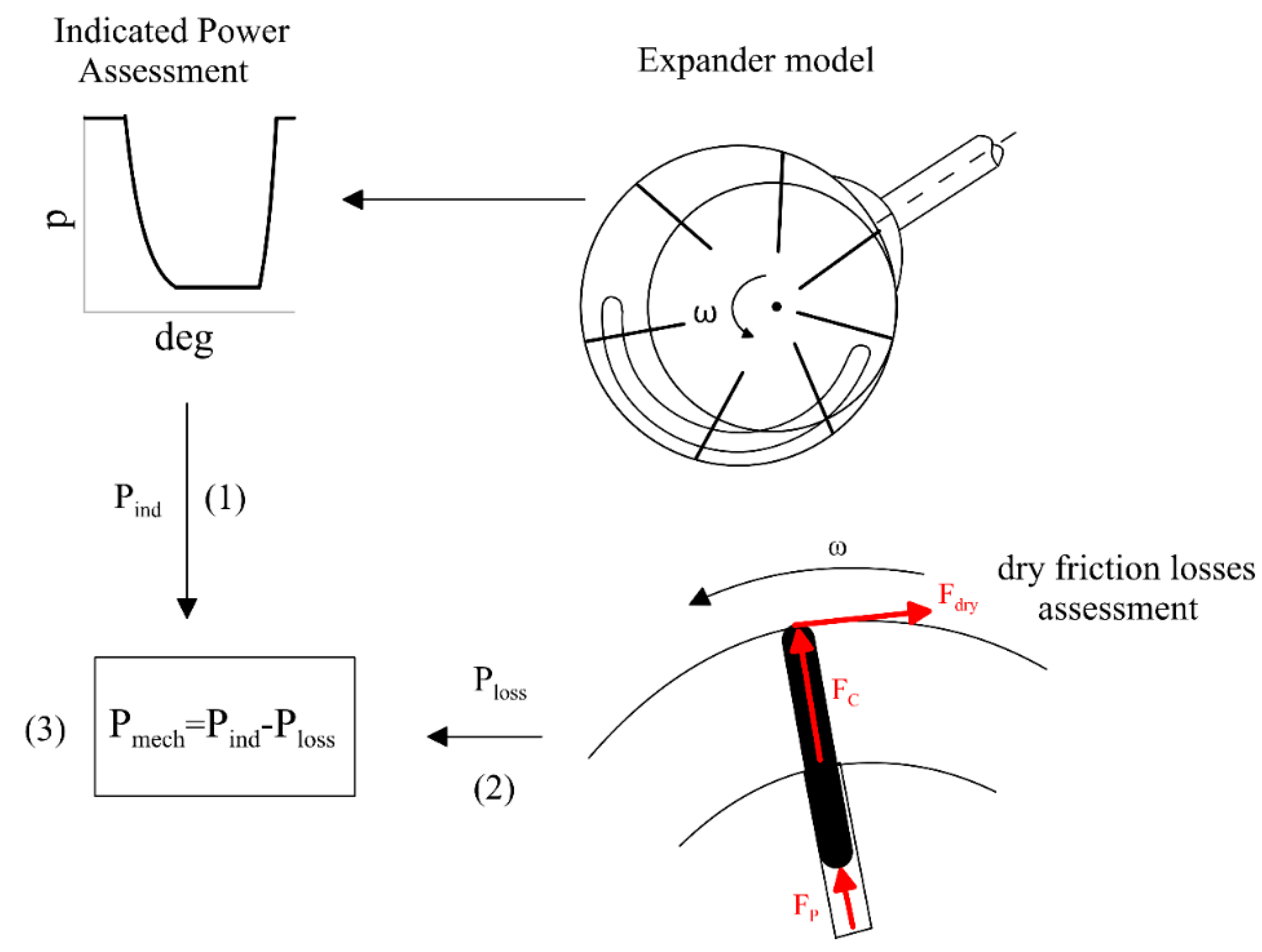
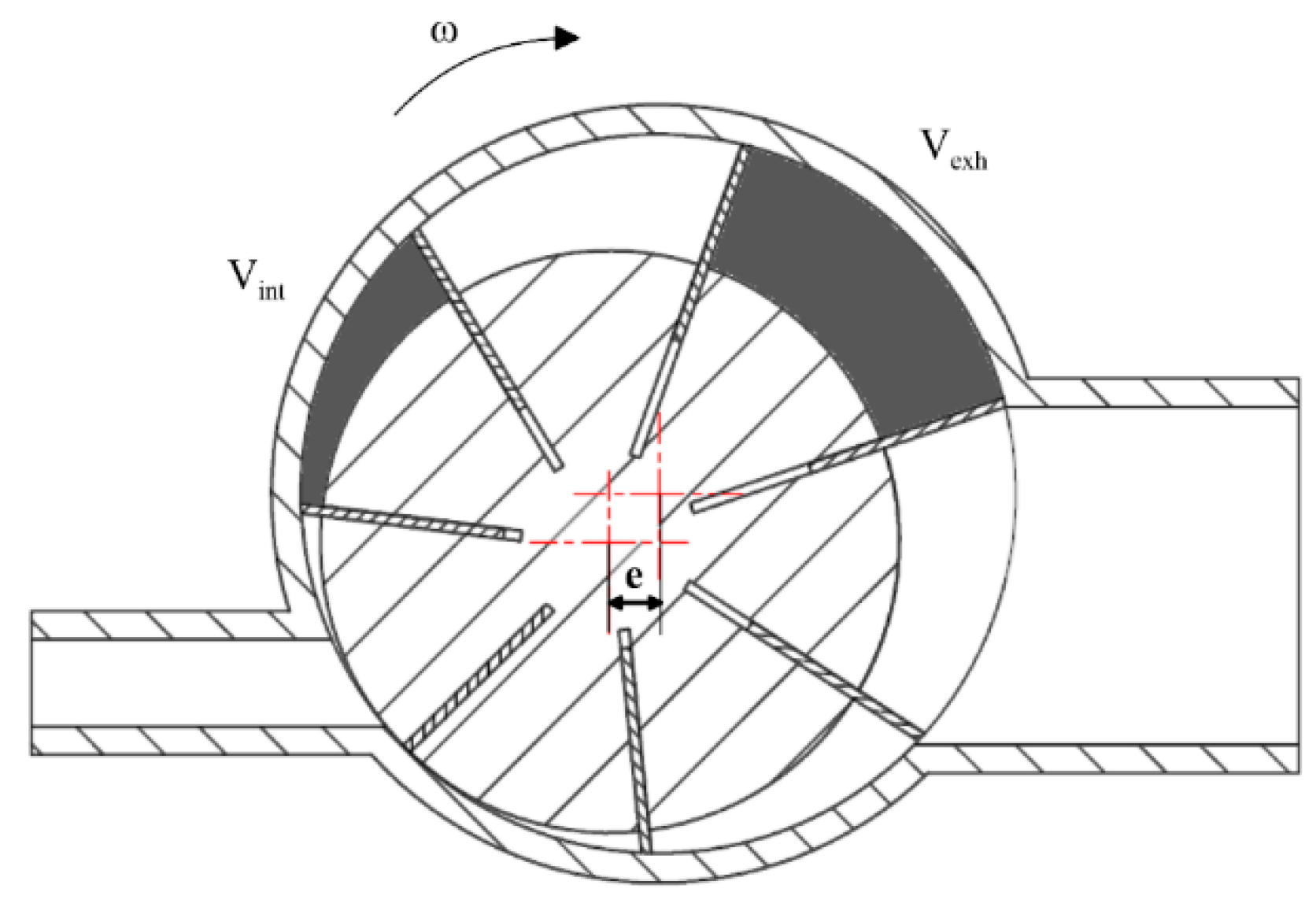
2.1. Mathematical Model of SVRE

The reason for a new model of an SVRE stands on the need to have a good compromise between the existing models and a simpler representation that doesn’t sacrifice the representation of the most relevant phenomena, which influence volumetric and mechanical efficiencies of the machine. Existing models have a high degree of reproducibility of real phenomena [40,41]. They are based on matching a 1D transient model, which represents the filling and emptying of the vanes facing intake and exhaust ports, with a lumped parameter approach, which describes the thermodynamic properties of the working fluid inside the chambers. This class of models represents also the leakage paths between vanes and across the end-wall plates, as well as the friction losses inside the machine produced by the contact at tip blades and inside the rotor slots. The high accuracy of these models is witnessed by several contributions in the literature [40,41]. Of course, also the indicated diagram is well represented and the effects produced by some unconventional solutions, like for instance, a double port intake technology [43,44]. Weakest points of the SVREs are the low values of the volumetric and mechanical efficiencies, which risk vanishing the superior characteristics of these machines when compared with the dynamic or volumetric reciprocating machines (low revolution speed, absence of vibrations, wide off design capabilities, management of mixtures of liquid and vapor at saturation, flexible shaping, etc.). Hence, the model has been oriented to be precise as much as possible concerning these two parameters (volumetric and mechanical efficiencies) and leave sufficiently described other aspects, like the indicated efficiency. Concerning this last parameter, three phenomena are dominant: (1) the quantity of the working fluid inside the chambers at the intake port closing; (2) the quantity of the working fluid inside the chamber at the exhaust port closing; (3) the effect of the leakages on the pressure inside the chambers. Among these, the first and the second one would require an unsteady approach (here neglected), while the third one has been solved in the new model with a simpler approach, without losing accuracy.
The volumetric losses are due to the leakages that take place among the geometric and functional gaps of the machine. They are:
  • Between blade tip and stator inner surface;
  • Between rotor face and casing;
  • Between blade side and rotor slots.
The first leakage is recognized to have a heavier detrimental effect on expander volumetric efficiency. Indeed, the gap puts into communication adjacent chambers, thus affecting the phases (intake, expansion, and exhaust), which each chamber performs. In particular, when a chamber is performing the intake phase, part of the entering working fluid escapes towards the adjacent chambers across the gap. A suitable quantity of oil mixed with the working fluid reaches the stator surfaces, thanks to the centrifugal forces, and ensures the absence of dry contact and a sensible contribution to the sealing of the vanes but, anyway, leakages occur. This causes the real mass flow rate entering the expander ( W F ) to be higher than the maximum allowable theoretical one (ṁth, Equation (1)). The ratio between these two values is the volumetric efficiency of the machine (Equation (2)):
t h = ρ i n , e n d V i n , e n d N v ω
η v o l = t h W F = ρ i n , e n d V i n , e n d N v ω W F
W F being easily measurable upstream of the machine. The leakages taking place between adjacent chambers are driven by the angular phase shift of the pressure profiles [41]. The geometrical choices of the machine influence these volumetric losses through the leakage area too.
In the new model here presented, the filling and emptying of the vanes have been assumed as steady, fixing the pressure inside the vanes simultaneously faced with the ports. For the inlet port, the static pressure at the expander inlet is represented by the highest pressure of the plant, i.e., the thermodynamic top pressure of the Rankine’s cycle. Similarly, during the emptying phase, all the vanes faced to the exhaust port assume instantaneously the downstream pressure (at the condenser). The intake phase phenomena and leakages are described according to the procedure reported in Figure 1. For the sake of comprehension, consider that the angular displacement of the intake port area can feed two chambers simultaneously (see Figure 1). The pressure inside the chambers is assumed to be equal to the upstream static pressure, known immediately before the port opening. In Figure 1, three chambers are considered: the one that is performing the intake phase (named ch1), the following (ch2), and the previous chamber (ch7), seen in the revolution speed sense. After the filling, during the expansion phase, the pressure is calculated during rotation, considering an adiabatic transformation. The initial mass inside the vane, when it is fully closed (having crossed the inlet port), tends to be varied due to leakages. An iteration procedure is needed in order to respect the continuity equation and energy conservation inside the rotating cells.
The model considers the leakages among vanes and between rotor face and end-wall plates following a lumped parameter approach. This consists of representing the leakage area as an equivalent orifice, whose diameter is evaluated through Equation (3a) for tip blade leakages and through Equation (3b) for leakages at the end-wall plate (Steps 2 and 3 in Figure 1).
d e q = 4 A l e a k π = 4 ( δ t i p W e x p ) π
d e q = 4 A l e a k π = 4 ( δ e n d w a l l d s t a t ) π
Clearances at blade tip (δtip) and between rotor face and end-wall plate (δend-wall) are experimentally identified, and the chamber width (Wexp) comes from geometrical data. Once the equivalent orifice is defined, as well as the pressure difference across vanes (also during subsequent iterations before convergence), the leakage mass flow rate (ṁleak) can be evaluated. The relation that rules this phenomenon is the one representing the flow across a lumped orifice ([45]), and it is depicted by Equation (4a) for leakages at tip blade and Equation (4b) for leakages taking place at the end-wall plate:
l e a k , t i p ( θ ) = c d A l e a k ρ 2 | p i ( θ ) p i 1 ( θ ) | ρ
l e a k , e n d w a l l ( θ ) = c d A l e a k ρ 2 | p i n t a k e p e x h a u s t | ρ
The relation allows to evaluate ṁleak among one chamber and the adjacent as a function of rotor angle (θ), represented by Step 5 in Figure 1. The absence of the occurrence of the sonic flow on the leakage area allows to consider Equation (4) of a wide validity. A sketch of the leakage representation is given in Figure 1: the fluid moves toward the passage area, contracting its fluid vane in an adiabatic reversible way. So, when the fluid approaches the area, a nozzle flow is considered, followed by a sudden enlargement flow in which kinetic energy is lost, and the static pressure at the throat area is assumed to be equal to the static pressure inside the vane where the fluid is escaped. The same phenomena are repeated for a subsequent couple of vanes. A similar representation applies also for the leakages across the end-wall plates.
The solution of the mass and energy conservation equations allows to evaluate, after a simple iterative procedure, the pressure inside chambers during rotation, the flow rates in-taken and expelled, the leakages between vanes and the indicated work (5). Once the pressure is known during the whole vane rotation, the indicated power Pind can be calculated according to Equation (5) (Step 6 of Figure 1).
P i n d = i = 1 N v p i d V i t c y c l e
Considering the geometry of the expander and the boundary conditions as in Table 1, the volumetric efficiency can be evaluated, as well as the intrinsic behavior of the machine expressed in terms of pressure profile and the corresponding leakages (Figure 2).
In Figure 2a, the indicated cycles referred to chamber 1 and chamber 7 (which precedes chamber 2 in the sense of rotation) are reported. Here, the constant pressure intake and discharge phases are evident, as well as the expansion and recompression, which deviate from an ideal adiabatic transformation (due to leakages). Indeed, the pressure trend during the expansion departs from the one obtained considering mass constant during the adiabatic isentropic transformation (represented by the dashed line). The pressure difference is the main driver of the leakages among the chambers [41]; indeed, for what concerns the one at tip blades between chamber 1 and 7 (Figure 2b), it takes place in the angular interval in which there are pressure differences among the adjacent chambers. Differences occur between the present new model and the advanced theoretical model (which considers a 1D transient phenomena inside the pipes connecting vanes and ports, so closely reproducing real phenomena), but the basic variations are caught vs. rotor angle, Figure 2b. The advanced theoretical model is the one discussed in [40,41]: when the fluid leaves chamber 1, it assumes a negative sign; otherwise, if the fluid coming from chamber 7 enters chamber 1, it assumes a positive sign. The results indicate a good matching, considering that the theoretical model adopts the following simplifications:
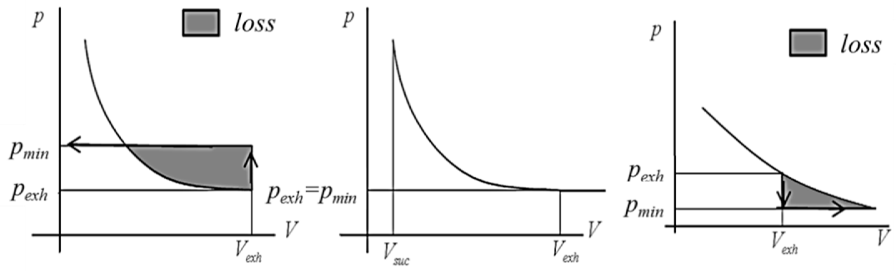
  • The intake and exhaust phases are considered as isobaric transformations;
  • The dynamic phenomena taking place at intake and exhaust phases are not considered.
The same conclusion applies also for the indicated cycle angular shift (Figure 2c) between chamber 1 and chamber 2 (which follows in the sense of rotation) and the corresponding leakages (Figure 2d).
Besides the volumetric machine characterization, the theoretical model allows also to reproduce its mechanical behavior. In Figure 3, the procedure adopted is shown. The evaluation starts introducing in a mechanical subroutine the indicated power carried out by the volumetric analysis reported above. Subtracting to this value the power loss due to friction Ploss, the mechanical power can be evaluated as in (Equation (6)):
P m e c h = P i n d P l o s s
Thus, Ploss results from the contact at tip blade between the blade and inner stator surfaces mediated through the oil film, inside the slots of the rotors where the blades move alternately and at the contact between the rotor and end plates [41]. When all the forces are accounted for, the resulting component normal to the surfaces in relative motion can be obtained; the product of this component with the friction coefficient gives the power lost by friction. In the new theoretical model, only the contribution at tip blade is considered, having observed that it is the main term [40,41]. The friction power at tip blade has been expressed as in Equation (7):
P l o s s = C t i p N V F N r V ω
In particular, FN is given by the sum of the centrifugal force (FC, Equation (8)) and the force exerted by the fluid under the blades (Fp, Equation (9)). It is worth noting that friction coefficients have been identified by experimental comparisons.
F C = m b ω 2 r v
F p = p b W e x p t b
Once the mechanical and indicated powers are known, it is possible to evaluate the mechanical ηmech (Equation (10)) and indicated efficiency ηind (Equation (11)). In particular, mechanical efficiency is expressed as the ratio between mechanical and indicated power, while the indicated efficiency by dividing the indicated power by the power associated with an isentropic expansion (having accounted for the residual power due to the recompression).
η m e c h = P m e c P i n d
η i n d = P i n d WF ( h i n h o u t , i s )
The product of indicated and mechanical efficiency provides the value of the global efficiency (Equation (12)).
η g l o b = η i n d η m e c h = P i n d W F ( h i n h o u t , i s )   P m e c h P i n d = P m e c W F ( h i n h o u t , i s )
Concerning the thermal losses, they are not considered by the model because the expander in the real experimental condition is fully insulated. Moreover, all the transformations inside the device can be considered adiabatic as they are very fast. In reality, as it has been assessed by the authors in previous work [40,41], the observation of the real pressure trace measured by a sequence of fast response pressure transducers shows values greater than those obtainable, considering an adiabatic transformation. The reason is due to the leakages, which allow the hotter fluid to enter an adjacent vane through clearances, modifying the pressure.

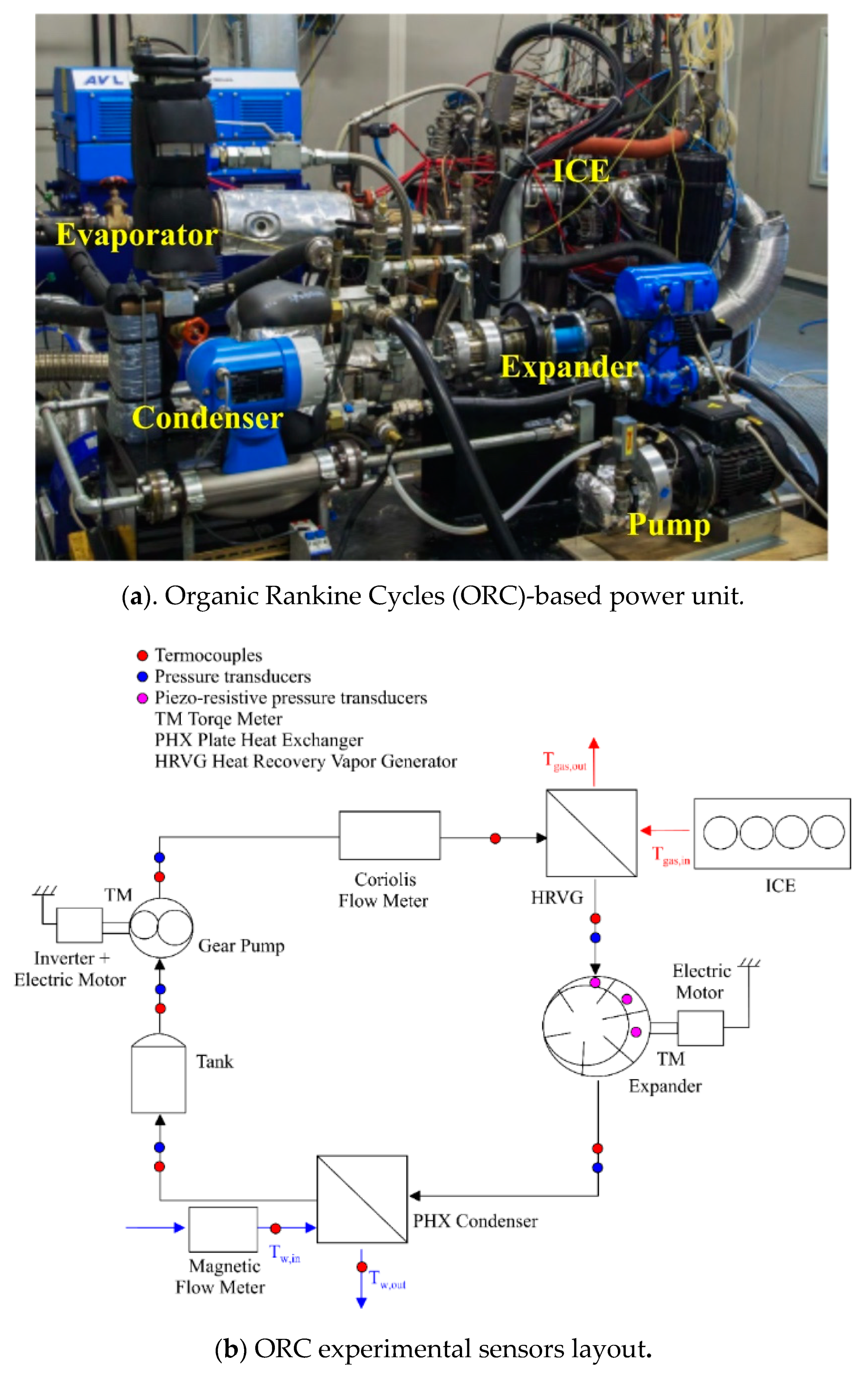
2.2. Experimental Validation

In order to use the model as a design software platform, a validation, thanks to the data collected during the experimental campaign [40,41], was needed. In Figure 4a and in Figure 4b, the experimental setup is reported. It was composed of:
-
A volumetric gear pump, which circulates the fluid. Thanks to an inverter, the revolution speed (and consequently the mass flow rate) can be changed;
-
A plate and fin evaporator;
-
A Sliding Vane Rotary Expander, linked to the electric grid via an electric generator;
-
A plate heat exchanger, acting as a condenser and cooled by tap water;
-
A tank, upstream the pump, which allows to dump the mass flow rate fluctuation and to decouple the minimum plant pressure from the mass of working fluid inside the plant.
The working fluid was R236fa, mixed to 5% of the working fluid mass of POE oil to lubricate the rotating machines and to behave as sealing fluid. In particular, the mass flow rate of working fluid was measured by a Coriolis flow meter, while the cooling water mass flow rate by a magnetic flow meter. The pressure inside chambers was measured by sequencing a series of piezoelectric transducers in order to experimentally reconstruct the thermodynamic cycle. Pressures and temperatures upstream and downstream of each component were measured as well. Finally, thanks to two torque-meter installed on the pump and on the expander shafts, the corresponding mechanical powers could be measured.
For what regards the acquisition of the experimental data, the same procedure reported in [41] was adopted. Once the ICE working condition was set, before starting the acquisition, the time needed by the ORC-based power unit was waited (10 min). The data acquisition was performed through a software developed by the authors in NI Labview™ software (National Instruments, Austin, TX, USA). Data were acquired for 5 s at 4500 Hz. This high value was chosen to reconstruct with good accuracy the p-θ indicated cycle. Indeed, being the expander revolution speed fixed at 1500 RPM, the expander in the acquistion period performed 125 revolutions with a pressure value measured every 2° of rotation. The uncertainty of measurement of the different quantities is reported in Table 2, while more details on the experimental campaign and on the experimental facility are reported in [40,41]. The experimental campaign was focused on the expander as it is considered the key component of the ORC-based power unit. The expander tested presented the intake and exhaust port, respectively, in radial and axial positions. Its main geometric features are reported in Table 1.
Mass flow rate, volumetric efficiency, and indicated and mechanical power predicted by the theoretical model were compared with the experimental data when certain values of intake and exhaust pressure and temperature and expander revolution speed were set as boundary conditions. In particular, the revolution speed was set equal to 1500 RPM, as the expander was constrained to rotate at such velocity. Moreover, also the predictions of the advanced theoretical model developed by the authors [40,41] were considered in the comparison: as already observed, these results came from a much more complex and comprehensive model, but high demanding in terms of computational time and prediction set up. This model could be considered as reference one because the hypotheses introduced for the simplified model here presented were not assumed.
Nonetheless, the simplified theoretical model (black points in Figure 5) allowed to predict the value of mass flow rate (Figure 5a), volumetric efficiency (Figure 5b), and indicated (Figure 5c) and mechanical power (Figure 5d), satisfactorily close to the corresponding experimental values.
Indeed, for the mass flow rate, the maximum deviation was equal to 13%, while the Root Mean Square Error (RMSE) equaled 3.6%. Similarly, volumetric efficiency predictions showed a maximum deviation equal to 6%, and the RMSE was 2.3%. Concerning Pind, the theoretical model allowed to achieve an RMSE of 5% with a maximum deviation of 19%, while for Pmech, the RMSE was 3%, and the maximum deviation was 18%. Figure 5 reports also the predictions obtainable with an advanced theoretical model [41] (red point), and it can be noticed that they were close to the theoretical ones given by the new model. Indeed, when the new model was adopted to reproduce the expander behavior in terms of WF, ηvol, Pind, and Pmech, the RMSE and maximum deviation were slightly higher but comparable to the theoretical predictions obtained, thanks to an advanced theoretical model. The main reason for these differences between the two theoretical models is due to the indicated power prediction, with the intake and the exhaust phases being considered at constant pressure in the new model. The effects were evident when the indicated power was represented. This can be seen in Figure 6, where the indicated cycle measured and predicted by the theoretical simplified and the theoretical advanced model is shown.
Two intake pressure values (10.2 bar (a) and 8.5 bar (b)) were considered. It can be noticed how, despite the theoretical simplified model is not able (by definition) to catch the pressure oscillation during intake, it allowed to reproduce the overall trend of the pressure inside the vanes and, consequently, the area below the cycle (as confirmed by the low errors in terms of Pind, shown in Figure 5c).
In Figure 5 and Figure 6, reference was made to an advanced theoretical model, which was developed by the authors in previous works [40,41]. It was used because it represents an advanced comprehensive model of the expander, which suitably mixes the unsteady nature of the flow on the intake and exhaust pipes, a lumped parameter model when the vanes don’t exchange mass across the inlet and outlet ports but exchange mass across leakages with more complex modeling. The 1-D analysis was employed to reproduce the dynamic phenomena inside the intake and exhaust pipes; the pipes were discretized into small elements and the Navier-Stokes equation (mass, momentum, and energy conservation equations). During the filling and emptying processes, vanes facing ports behaved like boundary conditions. This required complex modeling because vanes changed their volumes during the flow rate in/out, and the kinetic energy was lost or recovered or partially lost and recovered at the pipe end for the intake and at the pipe inlet for the exhaust. When the exhaust started, according to the pressure difference, the chocked flow could happen. During vane rotation, leakages modified the pressure inside vanes, producing a pressure during time diagram greater than the adiabatic trend, which should be the most suitable assumption considering the very fast process. So, an accurate leakage flow among vanes was modeled considering all the contributions. In this way, a very good agreement was reached for the volumetric efficiency of the machine. This allowed to identify the most suitable values for the clearance gap at tip blade δtip and between rotor face and end-wall plate δend-wall: 85 μm and 48 μm were found and used also in the simplified model presented here. In a similar accurate way, the mechanical efficiency was determined by measuring the shaft power and also the indicated power, thanks to a series of fast response pressure transducers, which record how pressure varies during rotation inside the vane. The advanced theoretical model solved the dynamic of the blade during its motion, deriving the forces applied to it. The friction coefficient was identified as equal to 0.01. These values were assumed in the simplified model.
Moreover, the theoretical advanced model tried to reproduce the pressure oscillation during intake and exhaust, thanks to the 1D transient model, which was needed to reproduce pressure oscillation (and masses pulsation), mainly at high pressure (intake). The new simplified model tried to stay on the experimental data, but secondary phenomena occurred, which could be represented neither by the theoretical advanced model. Pressure trace during exhaust was more correctly reproduced when the pressure before the exhaust port opening approached the downstream pressure. In this situation, pressure waves were negligible during exhaust. The simplified model predicted sudden recompression at the exhaust port opening, which didn’t take place in reality: this was due to the overestimation of the initial pressure from which expansion started at the intake port closing and to an only partial representation of the pressure inside the vane during expansion in the presence of leakages. As Figure 5d shows, the new theoretical model allowed to reproduce, with satisfactory accuracy, also the measured mechanical power (Pmech) through the correct representation of Ploss due to friction. Thus, a final confirmation of the capability of the simplified theoretical model to represent the expander performance was given by the comparison of mechanical efficiency (ηmech, Figure 7a). In Figure 7b, global efficiency (ηglob) is also shown. Indeed, in both cases, the simplified theoretical model ensured to reproduce the real data with a comparable accuracy with respect to the advanced theoretical model catching the trends.
Hence, the two main difference between the two models can be outlined:
  • The representation of the leakages;
  • The intake and exhaust phases were represented as isobaric transformation.
Concerning the first aspect, the representation of the leakages highly affected the capability of the model to return an accurate evaluation of the mass flow rate, volumetric efficiency, and, consequently, mechanical power produced by the machine form the influence on the indicated power. The simplified model assessed the leakages among adjacent chambers and between rotor face and end-wall plate through the equivalent orifice representation. Despite this approach was assessed as reliable, it led to higher errors than that of Poiseuille–Couette flow, which was implemented in the comprehensive advanced numerical model [41,42]. Concerning the second aspect, an instantaneous filling and emptying process was considered, neglecting the real processes, which involved pressure waves traveling inside the inlet and discharge pipes and the behavior of the vanes as boundary conditions of the 1D flows.
The simplified isobaric model had a great advantage for what concerns the computational time. Few seconds (less than 5 s for each case) were needed for a complete prediction of the expander performances, while the numerical advanced model required a computational time hundreds of times larger (10–15 min for each case). When used as an optimization tool, multiple cases were considered, so this version of the model required several hours, while the simplified model presented in this paper only very few minutes.

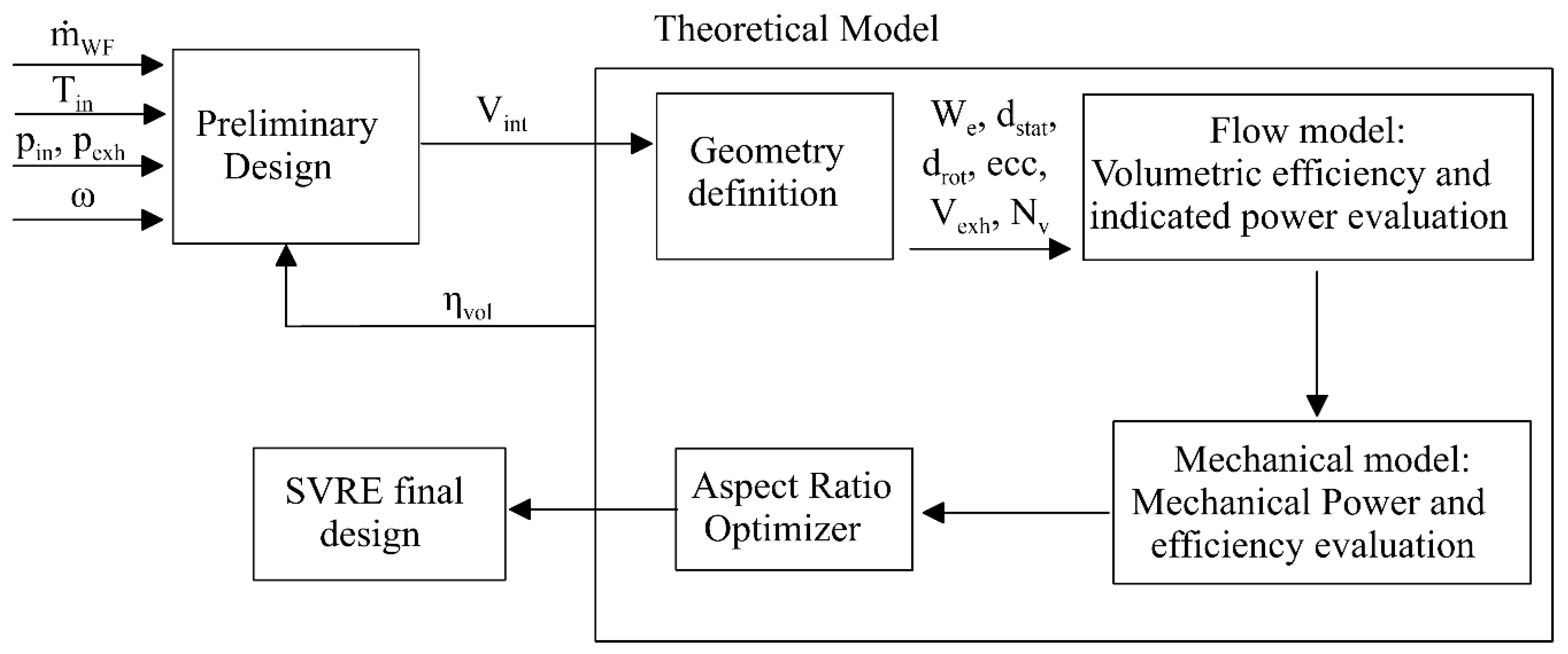
2.3. Model-Based SVRE Design

The validation process demonstrated as the new theoretical model presented allows to predict the expander performance with good accuracy.
These aspects give a strong expectation of the possibility of employing it in a model-based design procedure.
In order to verify this capability, the model can be used to evaluate the best geometry, which maximizes the machine performance (the combination of volumetric and mechanical efficiencies). The whole design procedure has an iterative nature and can be summarized in the flow chart reported in Figure 8.
The first step of the sizing process is the definition of the intake Vint and exhaust volumes Vexh (shown in Figure 9): the first is defined rearranging properly Equation (2) in order to obtain a Vint, which, for a given mass flow rate, ensures the desired intake pressure. Regarding volumetric efficiency, an initial value should be considered, which will be updated during the calculation. Concerning Vexh, this volume should guarantee the correct exhaust pressure according to the design pressure ratio. It could be preliminarily obtained, considering the expansion phase as an adiabatic-isentropic transformation with no leakages. So, the best Vexh is that value, which ensures that the chamber pressure at the exhaust start is equal to that exerted by the circuit at the expander outlet. This condition ensures that neither recompression during the discharge nor a sudden expansion will happen, both introducing a loss, Figure 10. Another important parameter, shown in Figure 9, is the eccentricity of the expander, which is the radius difference between the rotor and stator. This determines also the swept volumes and the size of the machine.
The ratio between Vint and Vexh represents the built-in volume ratio βV (Equation (13)).
β V = V e x h V s u c
However, in real situations, during the expansion phase, there is a mass exchange between adjacent chambers. For this reason, Vexh can’t be imposed as design input, but only preliminarily assumed and subsequently evaluated, thanks to the optimization procedure.
Once Vint is defined, and a proper βV is set, the same value of Vint could be achieved with different combinations of dstat, drot (and consequently the eccentricity), and Wexp. The geometric configuration of the SVRE can be described by the Aspect Ratio (AR) (Equation (14)), here defined as the ratio between the axial height (Wexp) and stator diameter (dstat).
A R = W e x p d s t a t
AR will be the result of the optimization procedure in order to guarantee the optimum global efficiency of the machine.
The theoretical model considers all the possible geometric configurations that ensure the intake volume provided by the preliminary design. Therefore, varying the expander width, the stator diameter must assume a certain value to guarantee that the intake volume is kept constant. Thus, if the expander width increases, the stator diameter decreases, as well as the eccentricity, because the rotor diameter is kept constant. On the other hand, if the expander width is reduced, the stator diameter must grow to avoid the intake volume variation. So, for each geometrical configuration, volumetric and mechanical efficiencies are calculated (for a given angular displacement of the intake and exhaust ports, Table 1) for different Aspect Ratios. The geometrical solution, which will predict the highest value of global efficiency, will be the optimum one.

3. Results

In order to assess the benefits introduced by the model-based design, the SVRE used in model validation was redesigned according to the presented procedure.
The first step was the definition of Vint, according to the operating conditions, in the pre-design phase. The operating condition considered was the one reported in Table 3. It is important to observe that the set point on the intake static pressure depended on the geometry of the machine, being it among the main cause of the permeability of the plant: from an engineering point of view, in fact, the maximum pressure (chosen after some thermodynamic evaluations) depends on the hydraulic “reaction” of the plant to a specific mass flow rate of the working fluid [40,41]. The concept of the permeability of the plant is very significant, and the SVRE (and its geometrical configuration) is the most influencing component.
Seven blades were considered, respecting the initial machine design; in reality, also this number should be chosen as the best compromise between the maximization of volumetric efficiency (which tends to increase with blade number) and that of mechanical efficiency (which increases, reducing blade number).
Equation (2) gives the preliminary design for Vint equal to 5.4 cm3. Knowing Vint, the iterative procedure was started in order to evaluate the best AR among the possible geometric configurations.
In Figure 11a, all the possible geometric configurations, which guarantee the achievement of the designed Vint, are reported. Here, it can be observed that when the vane axial height Wexp decreased from 80 mm to 30 mm, the eccentricity (keeping constant the rotor diameter at 65 mm) must grow from 4.1 mm to 11.3 mm. In other words, the SVRE passed from a “finger-shaped” to a “disk-shaped” geometry, depending on which dimension (the axial or radial one) was dominant. The AR reported, therefore, the shape appearance of the expander: its value ranged from 0.3 (when Wexp was 30 mm, and dstat was equal to 87.6 mm, like a “disk”) to 1.2 (when Wexp was 80 mm, and dstat was equal to 73.2, “finger-shaped”).
All these AR values ensured that the SVRE had a Vint close to 5.4 cm3, as shown in Figure 11b. However, despite Vint was the same, the built-in volume ratio (and consequently Vexh, which was a result of the calculation only preliminary imposed) varied from 4.1, when AR was 0.3, until to 3.3, for AR equal to 1.2. The results showed that when the AR decreased, the Vexh increased. The model consented to evaluate the performance of the SVRE for each AR. According to Figure 12a, the minimum AR (0.3) ensured to maximize both volumetric and mechanical efficiencies. Indeed, the volumetric efficiency increased from 0.44 to 0.50 when AR decreased from 1.2 to 0.3. Similarly, the mechanical efficiency grew from 0.89 to 0.95 for the same variation of AR. Concerning the global efficiency, despite it exhibited quite the same trend ranging from 0.34 to 0.33 (the maximum fell for AR = 0.7, but the values were very close in the AR range between 0.3 and 0.7), the benefits were lower compared to those observed for volumetric and expander efficiencies. This is because the indicated efficiency decreased with AR reduction. In fact, in higher AR machines (finger-shaped), the volumetric efficiency was lower (Figure 12a). This aspect involved that the machine should intake more mass flow rate to ensure a certain intake pressure, as reported in Figure 12b. This extra mass flow rate represented a severe penalization of the machine volumetric performance; however, similarly to what observed in [41], part of volumetric losses recirculated inside the chambers, providing a partial recovery effect in terms of indicated power. This recovery effect allowed to partially reduce the penalization in terms of global efficiency and to provide a slight increase in mechanical power. This effect can be seen in Figure 12b, where it can be observed that as AR increased from 0.3 to 1.2, the mechanical power grew from 977 to 1082 W, with an increase of about 10%.
Nevertheless, despite this effect on mechanical power, the high volumetric losses experienced for high AR significantly penalized the whole expander performance. Indeed, as aforementioned, for higher AR, the expander should intake a larger mass flow rate (up to 15%) with respect to the case of lower AR to achieve the required intake pressure (Figure 12b). Hence, when the AR was 0.3, the mass flow rate was 131 g/s, while when AR became 1.2, the mass flow rate increased up to 155 g/s. This extra mass flow rate led to a higher power required by the pump, which eroded the mechanical power advantage observed for higher AR. So, adopting lower AR, benefits could be observed, also from the whole plant point of view.
Therefore, considering all these results, the best design configuration, which ensures to achieve the best compromise between the maximization of global efficiency and mechanical power, was the one that showed an AR equal to 0.7. This expander shape involved a chamber width of 50 mm and an eccentricity of 6.6 mm (the stator diameter was 78.2 mm as the rotor diameter was kept constant to 65 mm). However, from the plant point of view, lower AR (0.3) ensured to obtain the minimum mass flow rate, which allowed ensuring the required intake pressure with a comparable mechanical power produced by the expander (Figure 12b). In this way, as the power required by the pump diminished, the advantages of the net power produced by the unit could be achieved. In any case, a “disk-shaped” machine (AR lower than one) was more efficient than a “finger-shaped” one (AR higher than one).
Obviously, other eventual geometrical constraints could be imposed in the optimization procedure in order to consider specific cases or boundaries.
With the aim to observe if the expander revolution speed can change the main features of the SVRE design, the model-based procedure was repeated considering a different revolution speed (2000 RPM). The results showed that a lower AR ensured to maximize the expander global efficiency. A higher revolution speed, of course, decreased the dimensions of the machine. This can be observed in Figure 13a, where, for the same expander width excursion (30–80 mm), the eccentricity (and consequently the radial encumbrance) was lower with respect to the previous case (lower revolution speed). For these values, AR varied from 0.3 to 1.2. The reduction of the dimensions was confirmed also by Vint, which was equal to 4.4 cm3 instead of 5.4 cm3, observed in the previous case (Figure 13b). The built-in volume ratio varied in a narrower range: in particular, from 3.86 to 3.22 when AR passed from 0.3 to 1.2.
Concerning the SVRE volumetric efficiency (Figure 14a), it increased with AR reduction in analogy with the lower speed case. However, the values were higher, because a reduction of volumetric losses due to the revolution speed increase was obtained, in accordance with the theoretical expectation. On the contrary, the higher revolution speed led to a lower mechanical efficiency with respect to the previous case. Indeed, when the revolution speed increased, the power loss due to friction grew (Equation (7)), and the mechanical efficiency decreased with AR. From the global efficiency side, which depends on the combined effect of volumetric, indicated, and mechanical SVRE performance, it can be noticed that it decreased with AR.
Moreover, at 2000 RPM, a slight improvement could be observed with respect to the lower revolution speed. In fact, for the higher revolution speed, when AR ranged from 0.3 to 1.2, the global efficiency varied from 0.35 to 0.32.
SVREs designed at higher revolution speeds presented slight benefits, also in terms of mechanical power produced. Indeed, even though the elaborated mass flow rate was equal in the two cases (Figure 14b) when the machine rotated at higher speed, it performed more cycles in a second, thus producing more power.
In fact, when AR was decreased from 1.2 to 0.3, the mechanical power decreased from 1100 W to 1055 W. The revolution speed at design point could not be increased too much because the higher was the revolution speed, the higher were the wear phenomena, which reduced the life of the machine. Thus, for all these reasons, an intermediate revolution speed between 1500 RPM and 2000 RPM was a good compromise.

4. Discussion

In the present paper, a new simplified theoretical model of the volumetric and mechanical performance of a Sliding Vane Rotary Expander is developed. Indicated performances are also represented. Models of SVREs have been extensively treated in the literature and have reached a very good level of prediction, but they are unsuitable to be used as design tools, considering the long computational times and general modeling set up. The model presented is conceived as a compromise between physical consistency and computational resources because the goal is the development of a suitable tool to assist the geometry optimization of the machine.
The physical consistency of the new model is displayed toward the predictions of volumetric and mechanical efficiencies, the most important parameters for these machines. Reduced computational times are reached, thanks to a specific simplification, which doesn’t affect the quality of the two aforementioned parameters. Intake and exhaust phases are simplified with respect to a 1D transient dynamic filling and emptying approach, while leakages among vanes and friction losses are represented with care as well as friction losses.
The model is validated, thanks to a wide experimental activity performed on an SVRE installed on an ORC-based power unit, built to recover the thermal energy of the exhaust gases of a 3 L supercharged diesel engine. The results show that, in spite of the intrinsic simplicity, the volumetric and mechanical efficiencies are represented with a satisfactory degree of precision, close to the real data, and those produced by a more complex model. Furthermore, the simplified theoretical SVRE model shows two main advantages:
  • It presents simulation times significantly lower with respect to the numerical model; few seconds characterize a complete prediction of the machine, while a more advanced theoretical model requires few hours;
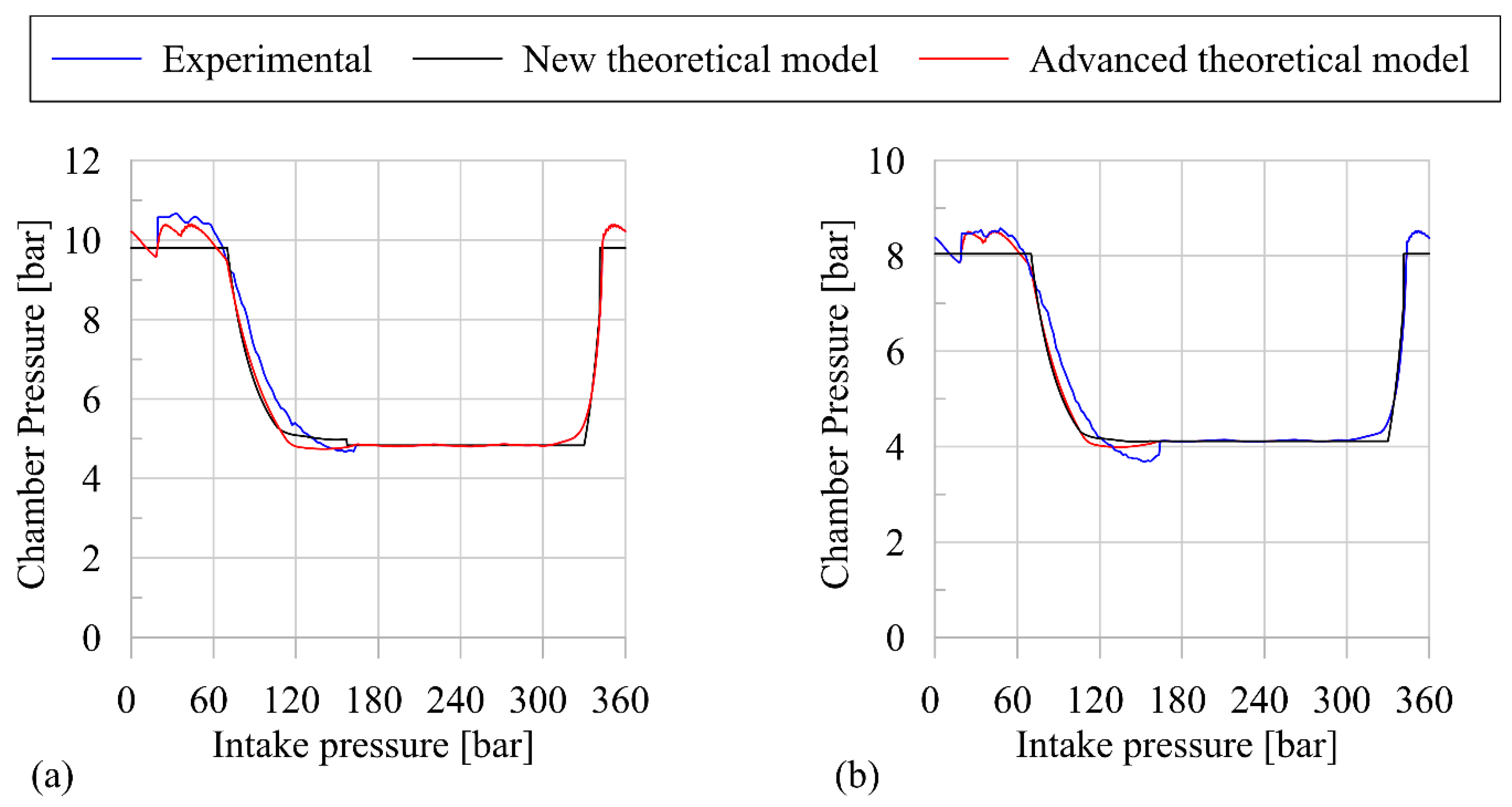
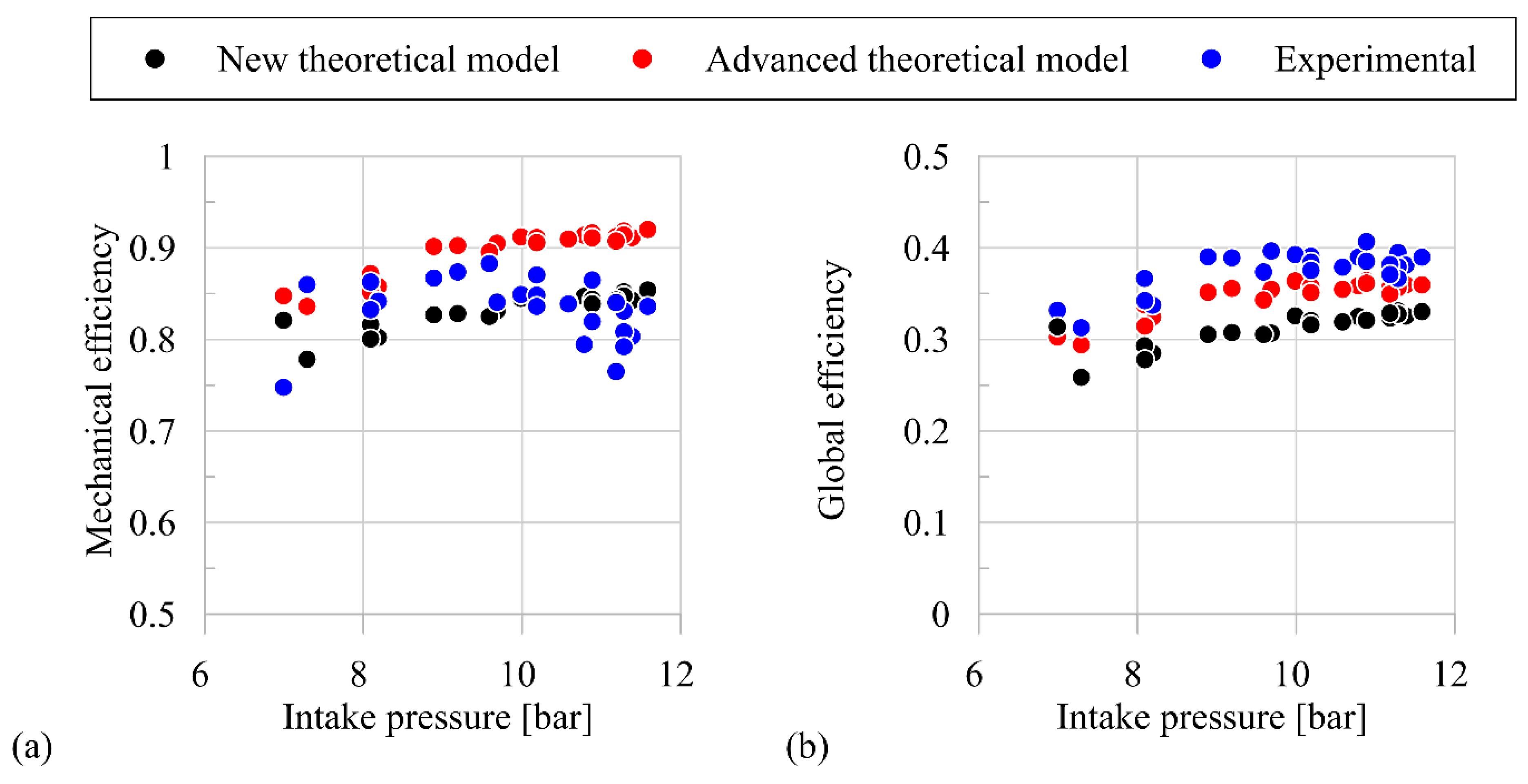
  • Once experimentally validated, the simplified model allows representing the whole behavior of the SVRE. Indeed, the predicted mass flow rate, volumetric efficiency, and indicated and mechanical power show a Root Mean Square Error equal to 3.6%, 2.3%, 5%, and 3%, respectively. Moreover, for all the quantities object of validation, the maximum deviations are lower than 20%.

5. Conclusions

In conclusion, the theoretical model is used as a virtual platform to optimize the geometry of a machine. An iterative procedure is developed, and, for a specific set of boundaries (static intake and exhaust pressure, intake temperature, expander revolution speed), a geometry is developed, which optimizes the whole performance of the machine (product of the volumetric and mechanical efficiencies). The results show that the best design strategies require:
(1)
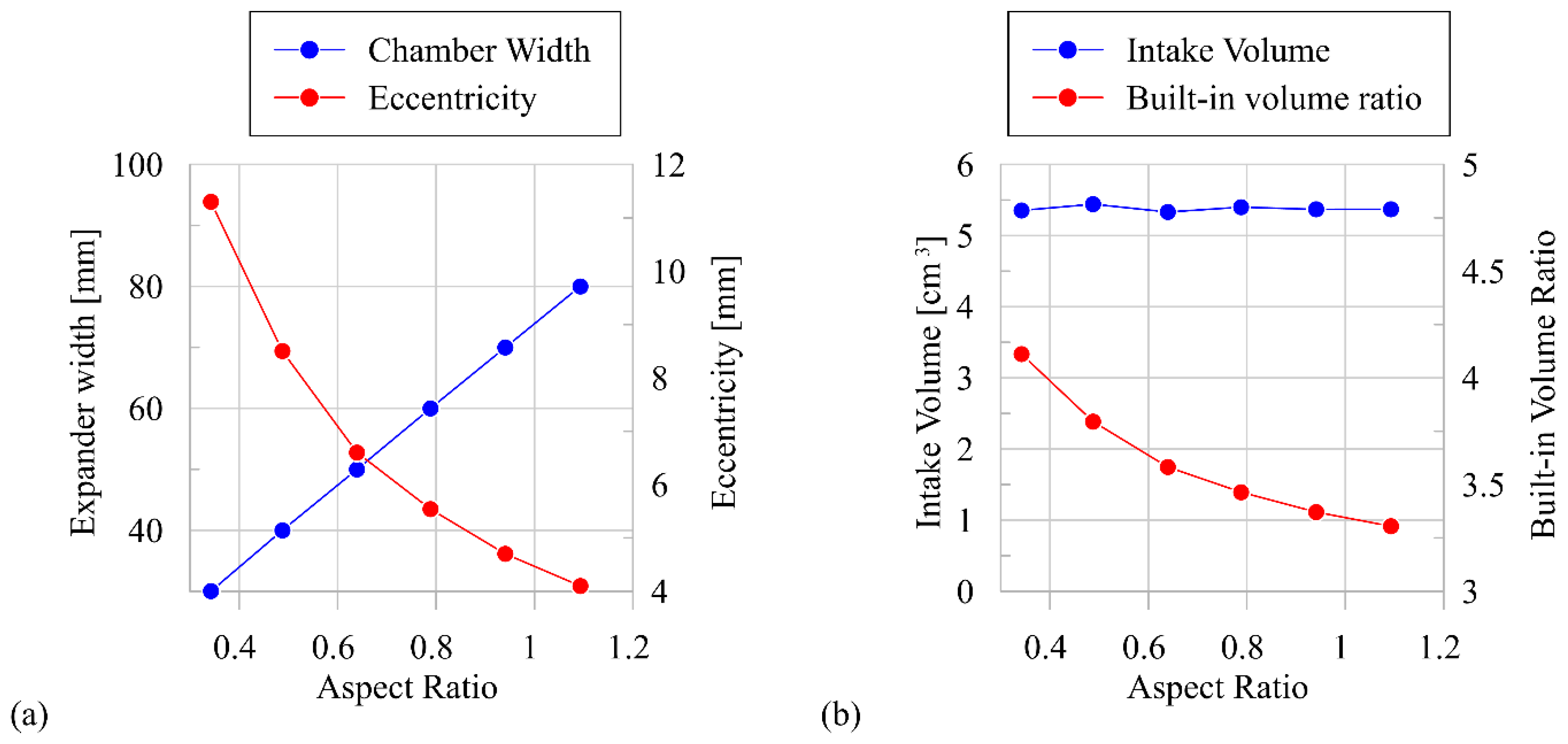
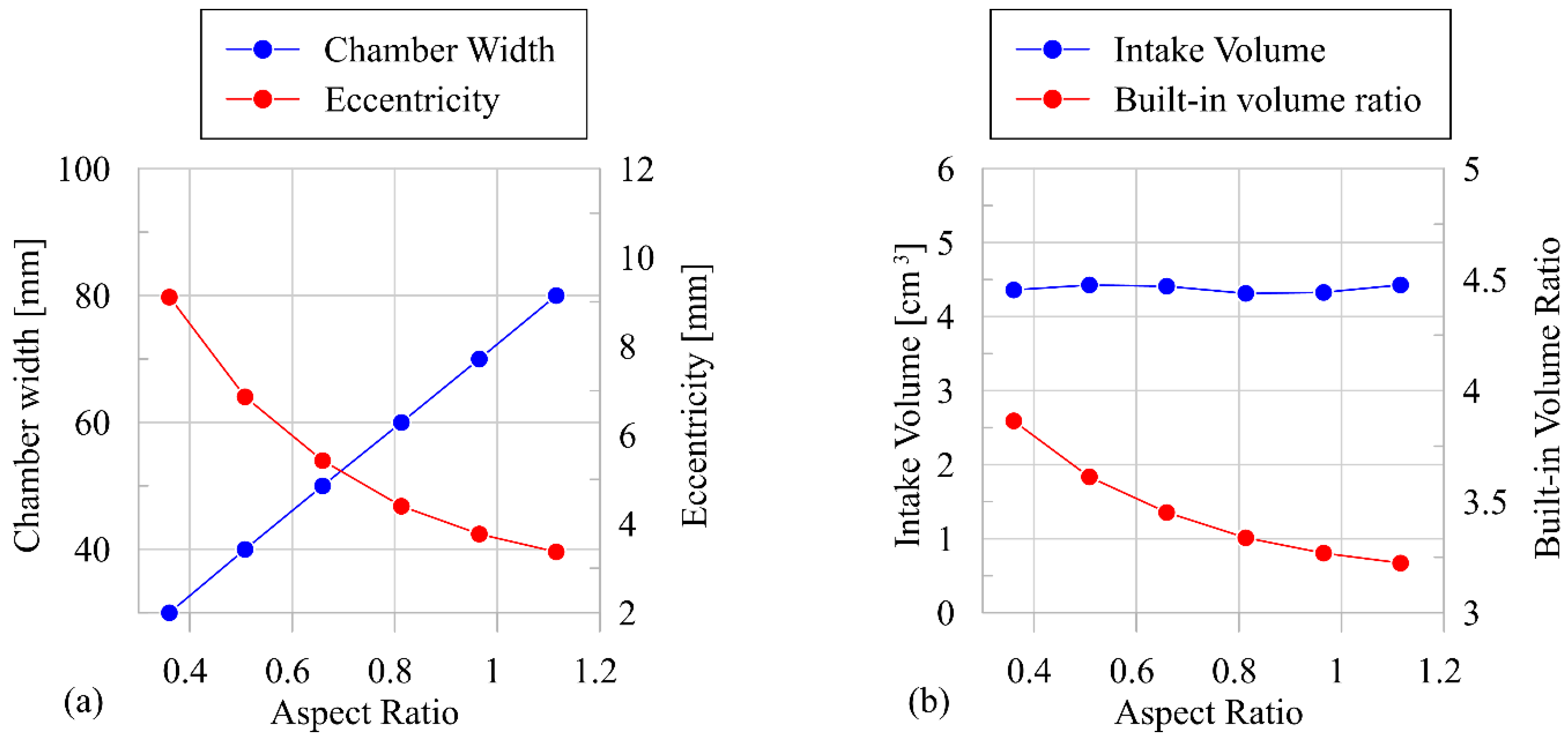
Reduction of the chamber axial length, increasing the machine eccentricity, to keep constant the intake volume. This orients the design toward a “disk-shaped” machine (instead of considering a “finger-shaped” type), which reduces the leakage area, thus improving the volumetric efficiency (up to 8% with respect to the tested configuration), which shows the heaviest effects on machine global efficiency. Moreover, an improvement of up to 4.3% of mechanical efficiency is also obtained. This indicates that vane axial length reduction produces also a stronger reduction in mechanical losses due to friction. In order to define a geometry type, a geometrical Aspect Ratio has been defined as the ratio between expander width and stator diameter;
(2)
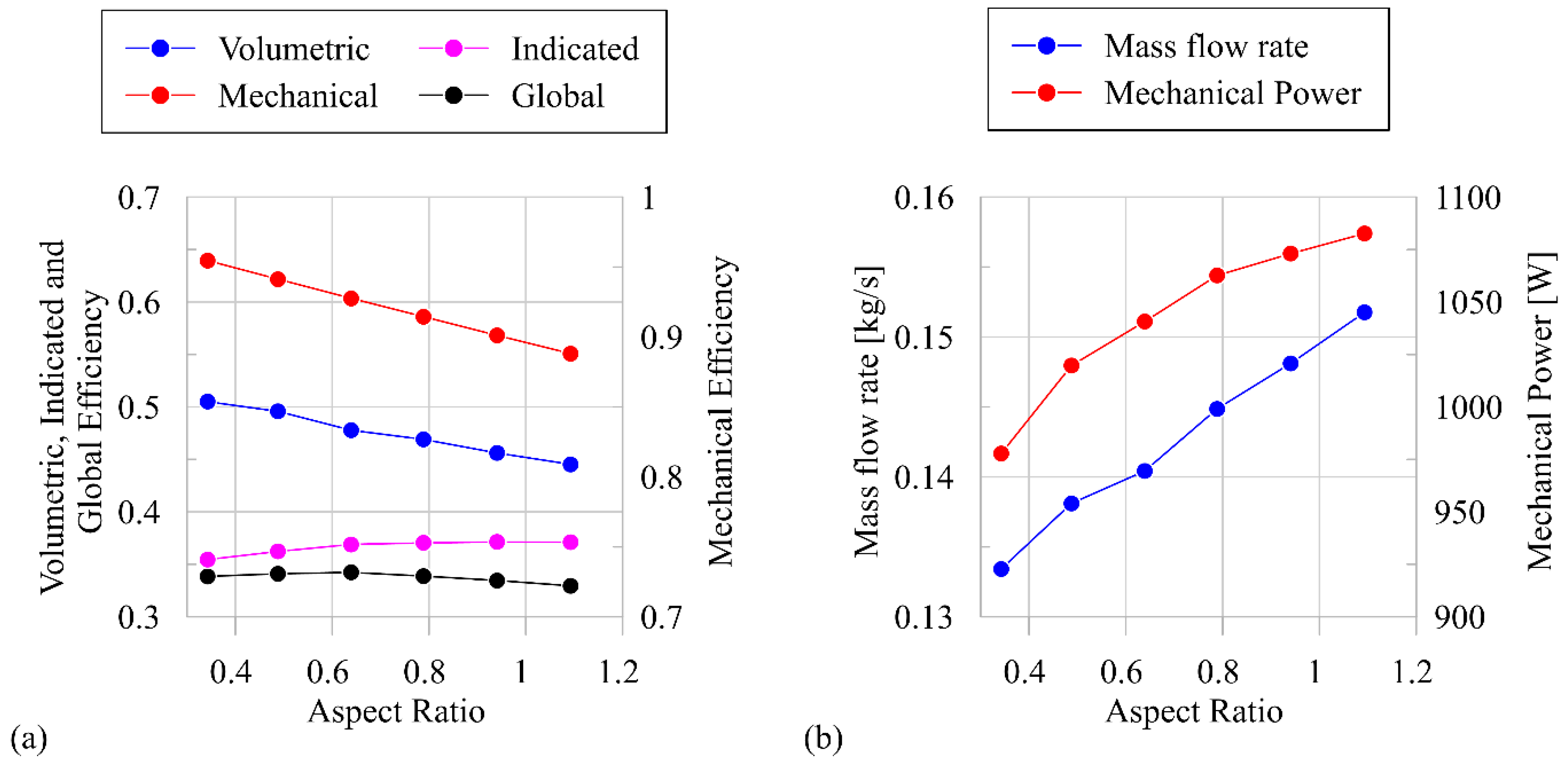
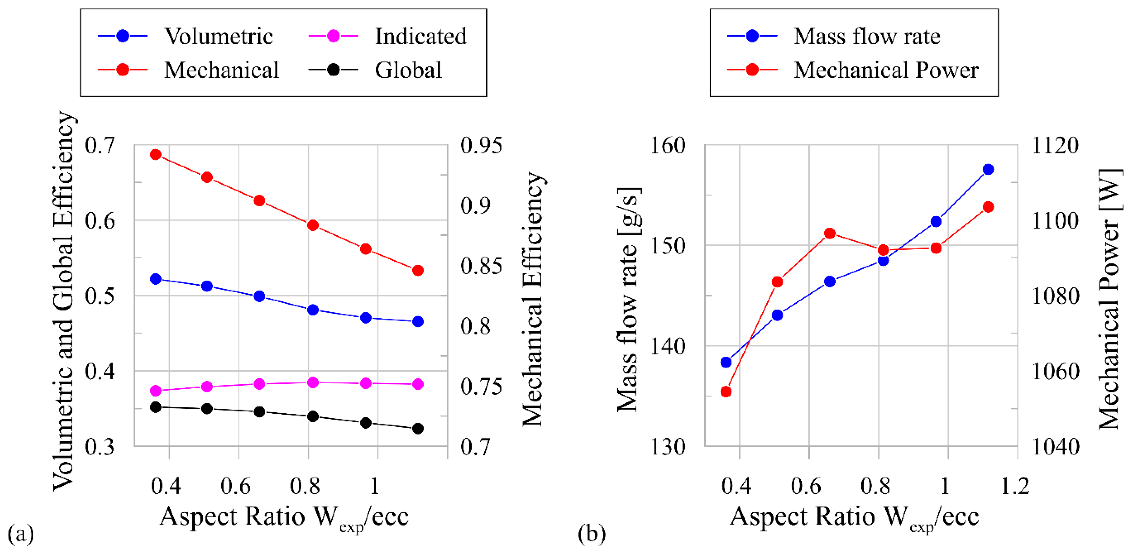
The increase of the Aspect Ratio (toward a “finger-shaped” machine) leads to a reduction of the SVRE efficiency. In particular, the volumetric and mechanical efficiencies decrease, respectively, up to 5% and 3%. On the other hand, an increase of the mechanical power is observed (+10% with respect to the original design), caused by the higher mass flow rate required by a “finger-shaped” configuration to guarantee the set point on the design intake pressure. Nevertheless, this power advantage is partially eroded by the higher power required by the pump to circulate the working fluid;
(3)
If the revolution speed increases, the overall machine performance increases too. Too high revolution speed, moreover, should be avoided because of the wear phenomena, which grow, as well as the centrifugal force (and consequently the friction losses). For these reasons, the intermediate value of design revolution speed (1500–2000 RPM) should be adopted for expander design for a machine mechanical power range of less than 5 kW.
Finally, the model opens the way to the possibility of implementing a model-based control, which is particularly useful for Waste Heat Recovery in mobile applications, where the high-temperature source significantly varies with time.

Author Contributions

Conceptualization, R.C. and F.F.; methodology, F.F. and D.D.B.; software, F.F.; validation, F.F. and M.D.B.; formal analysis, D.D.B.; resources, R.C.; data curation, F.F. and M.D.B.; writing—original draft preparation, F.F. and M.D.B.; writing—review and editing, D.D.B. and R.C.; visualization, D.D.B.; supervision, D.D.B. and R.C.; funding acquisition, R.C. All authors have read and agreed to the published version of the manuscript.

Funding

This research received no external funding.

Acknowledgments

The research was done in the framework of the European project “LONGRUN—Development of efficient and environmental friendly LONG distance powertrain for heavy duty trucks and coaches” and the POR-FESR project Hyper-Hybrid Propulsion for Electric Realignment.

Conflicts of Interest

The authors declare no conflict of interest.

Nomenclature

Symbolseq—Equivalent Orifice
A—Area [m2]exh—Exhaust
AR—Aspect Ratioexp—Expander
cd—Pressure Loss Coefficientglob—Global
C—Friction Coefficienti—Index of Chamber/Pressure Profile
ch—Chamberin—Intake
d—Diameter [mm]ind—Indicated
e—Eccentricity [mm]leak—Leakages
FN—Normal Force [N]loss—Mechanical Losses
h—Specific Enthalpy [kJ/kg]mech—Mechanical
mb—Blade Mass [g]out, is—Isentropic Condition at Expander Outlet
ṁ—Mass Flow Rate [kg/s]rot—Rotor
pb—Pressure Under the Blades [barg]stat—Stator
P—Power [W]th—Theoretical
p—Pressure [bar]tip—Tip Blade
Nv—Number of Vanes/Bladesvol—Volumetric
rv—Blade Tip/Rotor Center Distance [mm]WF—Working Fluid
tb—Blade Thickness [mm]
tcycle—Time Cycle [s]Greek Letter
T—Temperature [K], [°C]βv—Built-in Volume Ratio
Vint—Intake Volume [cm3]δ—Clearance Gap
Wexp—Expander/Chamber Axial Height [mm]η—Efficiency
θ—Rotational Angle
Subscriptsρ—Density
end-wall—Leakages at End-Wall Plateω—Expander Revolution Speed

References

  1. Shi, L.; Shu, G.; Tian, H.; Deng, S. A review of modified organic rankine cycles (orcs) for internal combustion engine waste heat recovery (ice-whr). Renew. Sustain. Energy Rev. 2018, 95–110. [Google Scholar] [CrossRef]
  2. Fu, J.; Liu, J.; Feng, R.; Yang, Y.; Wang, L.; Wang, Y. Energy and exergy analysis on gasoline engine based on mapping characteristics experiment. Appl. Energy 2013, 622–630. [Google Scholar] [CrossRef]
  3. Legros, A.; Guillaume, L.; Diny, M.; Zaïdi, H.; Lemort, V. Comparison and impact of waste heat recovery technologies on passenger car fuel consumption in a normalized driving cycle. Energies 2014, 7, 5273–5290. [Google Scholar] [CrossRef] [Green Version]
  4. Cipollone, R.; Di Battista, D.; Gualtieri, A. Direct Heat Recovery from the Ice Exhaust Gas, Institution of Mechanical Engineers-Sustainable Vehicle Technologies: Driving the Green Agenda; Woodhead Publishing: Gaydon, UK, 2012; pp. 177–187. [Google Scholar]
  5. Aghaali, H.; Ångström, H.-E. A review of turbocompounding as a waste heat recovery system for internal combustion engines. Renew. Sustain. Energy Rev. 2015, 49, 813–824. [Google Scholar] [CrossRef]
  6. Di Battista, D.; Carapellucci, R.; Cipollone, R. Integrated evaluation of inverted brayton cycle recovery unit bottomed to a turbocharged diesel engine. Appl. Therm. Eng. 2020, 175, 115353. [Google Scholar] [CrossRef]
  7. Di Battista, D.; Fatigati, F.; Carapellucci, R.; Cipollone, R. Inverted brayton cycle for waste heat recovery in reciprocating internal combustion engines. Appl. Energy 2019, 253, 113565. [Google Scholar] [CrossRef]
  8. Villante, C.; Anatone, M.; De Vita, A. A Distributed parameter approach for the modeling of thermoelectric devices. SAE Int. J. Engines 2018, 12, 1. [Google Scholar] [CrossRef]
  9. Wang, J.; Song, X.; Li, Y.; Zhang, C.; Zhao, C.; Zhu, L. Modeling and analysis of thermoelectric generators for diesel engine exhaust heat recovery system. J. Energy Eng. 2020, 146, 04020002. [Google Scholar] [CrossRef]
  10. Feidt, M.; Costea, M.; Feidt, R.; Danel, Q.; Périlhon, C. New criteria to characterize the waste heat recovery. Energies 2020, 13, 789. [Google Scholar] [CrossRef] [Green Version]
  11. Valencia Ochoa, G.; Piero Rojas, J.; Duarte Forero, J. Advance exergo-economic analysis of a waste heat recovery system using orc for a bottoming natural gas engine. Energies 2020, 13, 267. [Google Scholar] [CrossRef] [Green Version]
  12. Cipollone, R.; Di Battista, D.; Bettoja, F. Performances of an orc power unit for waste heat recovery on heavy duty engine. Energy Procedia 2017, 129, 770–777. [Google Scholar] [CrossRef]
  13. Carcasci, C.; Cheli, L.; Lubello, P.; Winchler, L. Off-Design performances of an organic rankine cycle for waste heat recovery from gas turbines. Energies 2020, 13, 1105. [Google Scholar] [CrossRef] [Green Version]
  14. Pantano, F.; Capata, R. Expander selection for an on board ORC energy recovery system. Energy 2017, 141, 1084–1096. [Google Scholar] [CrossRef] [Green Version]
  15. Di Battista, D.; Cipollone, R. Experimental analysis of an organic rankine cycle plant bottoming a heavy-duty engine using axial turbine as prime mover. SAE Int. J. Engines 2017, 10, 1385–1397. [Google Scholar] [CrossRef]
  16. Imran, M.; Usman, M.; Park, B.-S.; Lee, D.-H. Volumetric expanders for low grade heat and waste heat recovery applications. Renew. Sustain. Energy Rev. 2016, 57, 1090–1109. [Google Scholar] [CrossRef]
  17. Bao, J.; Zhao, L. A review of working fluid and expander selections for organic rankine cycle. Renew. Sustain. Energy Rev. 2013, 24, 325–342. [Google Scholar] [CrossRef]
  18. Clemente, S.; Micheli, D.; Reini, M.; Taccani, R. Energy efficiency analysis of organic rankine cycles with scroll expanders for cogenerative applications. Appl. Energy 2012, 97, 792–801. [Google Scholar] [CrossRef]
  19. Emhardt, S.; Tian, G.; Song, P.; Chew, J.; Wei, M. CFD modelling of small scale orc scroll expanders using variable wall thicknesses. Energy 2020, 199, 117399. [Google Scholar] [CrossRef] [Green Version]
  20. Stosic, N.; Ian, K.; Smith, A.K. Screw Compressors and Expanders, Positive Displacement Machines; Sultan, I.A., Phung, T.H., Eds.; Academic Press: Boston, MA, USA, 2019; pp. 115–142. [Google Scholar] [CrossRef]
  21. Ziviani, D.; Groll, E.; Braun, J.E.; Paepe, M.D. Review and update on the geometry modeling of single-screw machines with emphasis on expanders. Int. J. Refrig. 2018, 92, 10–26. [Google Scholar] [CrossRef]
  22. Bianchi, G.; Kennedy, S.; Zaher, O.; Tassou, S.A.; Miller, J.; Jouhara, H. Numerical modeling of a two-phase twin-screw expander for trilateral flash cycle applications. Int. J. Refrig. 2018, 88, 248–259. [Google Scholar] [CrossRef]
  23. Bianchi, M.; Branchini, L.; De Pascale, A.; Melino, F.; Ottaviano, S.; Peretto, A.; Torricelli, N. Application And Comparison Of Semi-Empirical Models For Performance Prediction Of A Kw-Size Reciprocating Piston Expander. Appl. Energy 2019, 249, 143–156. [Google Scholar] [CrossRef]
  24. Pantaleo, A.M.; Simpson, M.; Rotolo, G.; Distaso, E.; Oyewunmi, O.A.; Sapin, P.; De Palma, P.; Markides, C.N. Thermoeconomic optimisation of small-scale organic rankine cycle systems based on screw vs. piston expander maps in waste heat recovery applications. Energy Convers. Manag. 2019, 200, 112053. [Google Scholar] [CrossRef]
  25. Kolasiński, P. Experimental and modelling studies on the possible application of heat storage devices for powering the orc (organic rankine cycle) systems. Therm. Sci. Eng. Prog. 2020, 19, 100586. [Google Scholar] [CrossRef]
  26. Mascuch, J.; Novotny, V.; Vodicka, V.; Spale, J.; Zeleny, Z. Experimental development of a kilowatt-scale biomass fired micro–chp unit based on orc with rotary vane expander. Renew. Energy 2020, 147, 2882–2895. [Google Scholar] [CrossRef]
  27. Lemort, V.; Quoilin, S.; Cuevas, C.; Lebrun, J. Testing and Modeling a Scroll Expander Integrated Into an Organic Rankine Cycle. Appl. Therm. Eng. 2009, 29, 3094–3102. [Google Scholar] [CrossRef] [Green Version]
  28. Song, P.; Wei, M.; Zhang, Y.; Sun, L.; Emhardt, S.; Zhuge, W. The impact of a bilateral symmetric discharge structure on the performance of a scroll expander for ORC power generation system. Energy 2018, 158, 458–470. [Google Scholar] [CrossRef]
  29. Wang, T.; Zhang, Y.; Peng, Z.; Shu, G. A review of researches on thermal exhaust heat recovery with Rankine cycle. Renew. Sustain. Energy Rev. 2011, 15, 2862–2871. [Google Scholar] [CrossRef]
  30. Clemente, S.; Micheli, D.; Reini, M.; Taccani, R. Performance analysis and modeling of different volumetric expanders for small-scale organic rankine cycles. In Proceedings of the ASME 2011 5th International Conference on Energy Sustainability, Washington, DC, USA, 7–10 August 2011. [Google Scholar] [CrossRef]
  31. Shen, L.; Wang, W.; Wu, Y.; Lei, B.; Zhi, R.; Lu, Y.; Wang, J.; Ma, C. A study of clearance height on the performance of single-screw expanders in small-scale organic Rankine cycles. Energy 2018, 153, 45–55. [Google Scholar] [CrossRef]
  32. Dumont, O.; Parthoens, A.; Dickes, R.; Lemort, V. Experimental investigation and optimal performance assessment of four volumetric expanders (scroll, screw, piston and roots) tested in a small-scale organic Rankine cycle system. Energy 2018, 165, 1119–1127. [Google Scholar] [CrossRef] [Green Version]
  33. Musthafah, M.T.; Yamada, N. Thermodynamic analysis of expansion profile for displacement-type expander in low-temperature rankine cycle. J. Therm. Sci. Technol. 2010, 5, 61–74. [Google Scholar] [CrossRef] [Green Version]
  34. Vodicka, V.; Novotny, V.; Zeleny, Z.; Mascuch, J.; Kolovratnik, M. Theoretical and experimental investigations on the radial and axial leakages within a rotary vane expander. Energy 2019, 189, 116097. [Google Scholar] [CrossRef]
  35. Badr, O.; Probert, S.D.; O’Callaghan, P. Multi-vane expanders: Vane dynamics and friction losses. Appl. Energy 1985, 20, 253–285. [Google Scholar] [CrossRef]
  36. Badr, O.; Probert, S.D.; O’Callaghan, P.W. Multi-vane expanders: Internal-leakage losses. Appl. Energy 1985, 20, 1–46. [Google Scholar] [CrossRef]
  37. Yang, B.; Peng, X.; He, Z.; Guo, B.; Xing, Z. Experimental investigation on the internal working process of a CO2 rotary vane expander. Appl. Therm. Eng. 2009, 29, 2289–2296. [Google Scholar] [CrossRef]
  38. Kolasiński, P.; Błasiak, P.; Rak, J. Experimental investigation on multi-vane expander operating conditions in domestic CHP ORC system. Energy Procedia 2017, 129, 323–330. [Google Scholar] [CrossRef]
  39. Nikolov, A.; Brümmer, A. Investigating a Small Oil-Flooded Twin-Screw Expander for Waste-Heat Utilisation in Organic Rankine Cycle Systems. Energies 2017, 10, 869. [Google Scholar] [CrossRef] [Green Version]
  40. Fatigati, F.; Di Bartolomeo, M.; Di Battista, D.; Cipollone, R. Experimental and numerical characterization of the sliding rotary vane expander intake pressure in order to develop a novel control-diagnostic procedure. Energies 2019, 12, 1970. [Google Scholar] [CrossRef] [Green Version]
  41. Fatigati, F.; Di Bartolomeo, M.; Cipollone, R. On the effects of leakages in sliding rotary vane expanders. Energy 2020, 192, 116721. [Google Scholar] [CrossRef]
  42. Vodicka, V.; Novotny, V.; Mascuch, J.; Kolovratnik, M. Impact of major leakages on characteristics of a rotary vane expander for ORC. Energy Procedia 2017, 129, 387–394. [Google Scholar] [CrossRef]
  43. Fatigati, F.; di Bartolomeo, M.; Cipollone, R. Dual intake rotary vane expander technology: Experimental and theoretical assessment. Energy Convers. Manag. 2019, 186, 156–167. [Google Scholar] [CrossRef]
  44. Fatigati, F.; di Bartolomeo, M.; di Battista, D.; Cipollone, R. A dual-intake-port technology as a design option for a Sliding Vane Rotary Expander of small-scale ORC-based power units. Energy Convers. Manag. 2020, 209, 112646. [Google Scholar] [CrossRef]
  45. Gamma Technologies. GT-Suite™ Flow Manual; Gamma Technologies: Westmont, IL, USA, 2019. [Google Scholar]
Figure 1. The theoretical model of the expander filling. Step (1): Definition of pressure inside the chamber without leakages; Step (2): Evaluation of leakages at tip blade and at the end-wall plate with equivalent orifice theory (Step (3)); Step (4): Calculation of leakages as a function of rotation angle; Step (5): Evaluation of real mass inside chambers; Step (6): Updating of the indicated cycle considering leakages.
Energies 13 04204 g001
Figure 2. Pressure profile angle phasing between chamber 1 and chamber 7 (previous in the sense of rotation) (a) and corresponding leakages at tip blade (b); Pressure profile angle phasing between chamber 1 and chamber 2 (next in the sense of rotation) (c) and corresponding leakages at tip blade (d).
Energies 13 04204 g002
Figure 3. Mechanical section of the theoretical model. Step (1) Evaluation of indicated power as the area of the indicated cycle; Step (2) Evaluation of the power loss due to friction at tip blade; Step (3) Mechanical power evaluation as the difference between indicated power and power loss.
Energies 13 04204 g003
Figure 4. Experimental ORC-based power unit test bench (a) and scheme of sensors layout (b).
Energies 13 04204 g004
Figure 5. Comparison between experimental data and new theoretical and advanced theoretical predictions about WF (a), ηvol (b), Pind (c), and Pmech (d).
Energies 13 04204 g005
Figure 6. Comparison between experimental, theoretical, and numerical indicated cycle for an intake pressure equal to 10.2 (a) and 8.5 (b).
Energies 13 04204 g006
Figure 7. Comparison between experimental, new theoretical, and advanced theoretical prediction of ηmech (a) and ηglob (b).
Energies 13 04204 g007
Figure 8. Scheme of the design model.
Energies 13 04204 g008
Figure 9. Intake (left) and exhaust (right) volume.
Energies 13 04204 g009
Figure 10. Different kinds of exhaust loss at the expander outlet.
Energies 13 04204 g010
Figure 11. Results of the model-based design: (a) geometrical configuration; (b) built-in volume ratio.
Energies 13 04204 g011
Figure 12. Results of the model-based design: global, volumetric, indicated and mechanical efficiency (a), mass flow rate and mechanical power (b). The rotor diameter was fixed to 65 mm.
Energies 13 04204 g012
Figure 13. Results of the model-based design for revolution speed equal to 2000 RPM: (a) geometric configuration; (b) built-in volume ratio and intake volume.
Energies 13 04204 g013
Figure 14. Results of the model-based design increasing revolution speed up to 2000 RPM: (a) global, volumetric, indicated and mechanical efficiency; (b) mass flow rate and mechanical power. The rotor diameter was fixed to 65 mm.
Energies 13 04204 g014
Table 1. Expander geometry and input data.
Expander Geometry
Number of vanes7
Angular chamber extent [deg]51.4
Stator diameter [mm]75.9
Rotor diameter [mm]65
Eccentricity [mm]5.45
Expander width [mm]60
Blade thickness [mm]3.96
Blade length [mm]17
Intake port opening angle [deg]4.4
Intake port closing angle [deg]48
Exhaust port opening angle [deg]180
Exhaust port closing angle [deg]322
Boundary conditions
Static pressure at intake [bar]10.5
Static pressure at exhaust [bar]4.8
Temperature at intake [°C]83.6
Expander revolution speed [RPM]1500
Table 2. Uncertainties of measurement.
Physical QuantitiesUncertainty of Measurement
Working fluid temperature±0.3 K
Working fluid pressure±0.3 bar
Indicated cycle±0.1% of the full-scale sensor output
Working fluid mass flow rate±0.5% [kg/s]
Water mass flow rate±0.5% [kg/s]
Mechanical power±0.8% [W]
Volumetric efficiency±0.6%
Mechanical efficiency±2%
Global efficiency±2.2%
Table 3. Operating conditions.
Operating Conditions
Static pressure at intake [bar]13
Static pressure at exhaust [bar]3
Temperature at intake [°C]90
Expander revolution speed [RPM]1500
Mass flow rate [kg/s]0.150
Initial value of volumetric efficiency0.5

