1. Introduction
Large-scale renewable energy source (RES) bases in China are mostly located in renewable energy-rich areas far from the load center. The reverse distribution of RES and load leads to large-scale RES power being difficult to consume locally. A large amount of intermittent RES power needs to be delivered to the load center for consumption through long-distance transmission lines. The transfer capability of transmission lines is not sufficient during the peak periods of renewable primary energy, causing a severe RES power curtailment problem [
1].
The transfer capability of transmission lines is generally restricted by the transient stability total transfer capability (TSTTC) [
2]. TSTTC is the ability of the system to deliver power from the sending-end to the load center through transmission lines, under the condition that the system can stay transiently stable after contingencies occur. Therefore, improving the system transient stability can help in enhancing TSTTC. Several studies proposed methods for improving the system transient stability, as well as enhancing TSTTC from different aspects. One of the effective methods is active power control strategy, which reschedules the generation plans of thermal generation units to improve the system transient stability, thereby enhancing TSTTC [
3,
4,
5]. However, for the sending-end integrated with large-scale RES, the original generation plans of thermal generation units are made considering maximizing the consumption of RES power, and rescheduling generation plans may crowd out the consumption space for RES power. For this reason, studies analyzed the effect of the excitation system parameters of thermal generation units on transient stability, and they proposed methods of increasing the response ratio of excitation voltage and the force excitation threshold voltage to enhance TSTTC without changing generation plans. However, transient excitation enhancement is an open-loop control without feedback; thus, it cannot automatically adapt to the changes of system conditions, and it requires remote transmission of signals, resulting in reducing the reliability of the system [
6,
7]. In addition, with the application and development of flexible alternating current (AC) transmission systems (FACTS), the utilization of FACTS devices like thyristor-controlled series compensators (TCSC), static var compensators (SVC), and static synchronous compensators (STATCOM) can reduce the energy accumulation in generators during contingencies, thereby improving the system transient stability and enhancing TSTTC [
8,
9,
10]. Furthermore, studies found that superconducting magnetic energy storage (SMES) can also store the excess energy in generators during contingencies with a quicker response and more flexibility [
11,
12]. However, for systems without FACTS devices or energy storage, installing them needs a long planning time and big investment.
In addition to the methods above, through transient stability analysis, the Thevenin equivalent voltages of the sending-end and receiving-end have a significant influence on the TSTTC, and Thevenin equivalent voltages and reactive power are highly correlated; therefore, reactive power control can also enhance the TSTTC. In a power system, reactive power control is used to control the output of reactive power sources like generators, shunt reactors, and shunt capacitors, thereby adjusting the injecting reactive power into some nodes or the reactive power flow through some lines. At present, reactive power control is mainly used for voltage regulation and voltage stability maintenance [
13,
14,
15]; however, no previous work on enhancing TSTTC using reactive power control was reported.
A new reactive power control method for enhancing the TSTTC of transmission lines for a system with large-scale RES integrated into the sending-end is presented in this paper, with the following main contributions:
The sensitivity between TSTTC and reactive power is derived, and, with the sensitivity and TSTTC gap, the reactive power adjustment that is needed for filling the TSTTC gap can be calculated. Therefore, the TSTTC of transmission lines can be effectively enhanced by adjusting the reactive power of reactive power devices.
The proposed reactive power control method is especially useful for enhancing TSTTC for a system with large-scale RES integrated into the sending-end in its existing structure. Because the reactive power adjustment is available from the generators in conventional generation plants and the reactive-load compensation equipment in substations, it needs no further investment in terms of installing new devices.
Using reactive power control to enhance TSTTC does not involve active power changing; therefore, it will not crowd out the consumption space for RES power. With the enhanced TSTTC, the transmission lines are able to deliver more RES power to the load center, thereby reducing RES power curtailment.
This rest of the paper is organized as follows: in
Section 2, the sensitivity between the TSTTC of transmission lines and the Thevenin equivalent voltage is derived using equal area criterion. In
Section 3, the sensitivity between the Thevenin equivalent voltage and reactive power is derived using the total differentiation method. By connecting the above sensitivities together, the sensitivity between the TSTTC and reactive power is presented in
Section 4, along with the calculation methods to get the relevant parameters needed. In
Section 5, using the sensitivity between the TSTTC and reactive power as the control priority, the detailed reactive power control method for enhancing TSTTC is proposed. In
Section 6, the method is applied to the Gansu Province Power Grid to demonstrate its effectiveness. Finally, some conclusions are drawn in
Section 7.
2. Sensitivity between TSTTC and Thevenin Equivalent Voltages
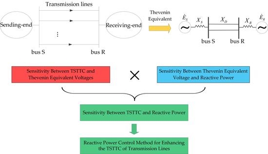
The schematic diagram of a system composed of a sending-end and receiving-end with transmission lines connecting them is shown in
Figure 1, and the sending-end is integrated with large-scale RES.
For the system shown in
Figure 1, according to Thevenin’s theorem, at any time, looking from bus S to the sending-end, the sending-end can be equivalent to a generator (Thevenin equivalent voltage
, Thevenin equivalent reactance
) [
16]. Similarly, the receiving-end is also equivalent to a generator (Thevenin equivalent voltage
, Thevenin equivalent reactance
). The equivalent resistance of the system is much lower than the reactance of long-distance transmission lines which is
; thus, so it is ignored. The equivalent model of the system is shown in
Figure 2.
The transmission power through the transmission lines is as follows:
where
.
Taking the
N − 1 fault on the transmission lines as the expected fault, TSTTC is the maximum allowable transmission power through the transmission lines, under the condition that the system can stay transiently stable after an expected fault occurs. Let
; then, the transient stability analysis of the two-equivalent-machine system is converted into a single-equivalent-machine system whose rotor motion equation is shown in Equation (2).
where
where
is the transient process moment,
is the reactance of different transient phases (pre-fault:
, fault:
, and post-fault:
), and
is the system inertia time constant.
According to the equal area criterion, if the system is under the critical condition of transient stability, as shown in
Figure 3, the equivalent rotor’s acceleration area A and the biggest possible deceleration area D are equal in the first swing. In this condition,
gets its maximum value
, which is the TSTTC of transmission lines [
5].
The difference between area D and area A is zero.
where
,
, and
are the initial angle, the fault clearing angle, and the critical angle, which are as follows:
where
is the fault clearing time.
We can then take Equation (6) into Equation (5) to get the expression of the relationship between TSTTC (
) and the Thevenin equivalent voltage (
) as follows:
Using the implicit function derivative rule with Equation (7), the sensitivity between the TSTTC and the Thevenin equivalent voltage
can be calculated as shown in Equation (8). Because
has the same position in Equation (7) as
, the sensitivity between the TSTTC and
is similar and omitted.
The detailed expression of
is presented in the
Appendix A.
3. Sensitivity between Thevenin Equivalent Voltage and Reactive Power
The sensitivity between and reactive power is derived in this section, and the sensitivity between and reactive power is similar and omitted.
In
Figure 2, the voltage of bus S is
, and the complex power injected into bus S from the sending-end is
. According to Kirchhoff law,
is as follows:
where
.
We can take the module value on both sides of Equation (9) as follows:
While adjusting the reactive power, the active power does not change and is considered as constant. We can then use the total differentiation method on Equation (10) to obtain Equation (11) as follows:
where, according to Equation (10),
and
are as follows:
Through the sensitivity between voltage and reactive power (
) and the reactive power transfer factor (
),
in Equation (11) can be converted into reactive power adjustment (
) as shown in Equation (14).
Taking Equation (14) into Equation (11), we get the expression of the sensitivity between
and reactive power as follows:
4. Sensitivity between TSTTC and Reactive Power
In
Section 2 and
Section 3, the sensitivity between the TSTTC and the Thevenin equivalent voltage in Equation (8) and the sensitivity between Thevenin equivalent voltage and reactive power in Equation (15) were derived. By connecting Equation (8) and Equation (15), the sensitivity between the TSTTC and reactive power is given in Equation (16).
According to Equation (16), if the reactive power of node changes by , then the TSTTC changes by accordingly. In order to obtain , it is known from Equations (16), (8), and (15) that two kinds of parameters are needed. The first kind can be read directly from the phasor measurement unit (PMU), the supervisory control and data acquisition (SCADA), and the system parameter database, including , , , , and . The second kind of parameter needs to be calculated first, including the Thevenin equivalent parameters (,,,), the sensitivity between voltage and reactive power (), and the reactive power transfer factor (). The methods to calculate them are provided below.
4.1. Thevenin Equivalent Parameter Identification
Thevenin equivalent parameters are affected by the grid topology, power generation condition, load condition, etc. Each time the reactive power is adjusted, Thevenin equivalent parameters should be updated. In this paper, the Thevenin equivalent parameters were identified using a tracking algorithm based on variation correction. The algorithm modifies the Thevenin equivalent parameters in the previous condition based on real-time conditions, thereby quickly obtaining those in current conditions [
16].
Taking the sending-end shown in
Figure 2 as an example, and taking the phase angle of
as reference, which is
, by expanding Equation (9) according to the real and imaginary parts, the Thevenin equivalent parameters are expressed as follows:
The main process is to continuously update in the current condition () through deviation correction, and then use Equation (17) to obtain and .
The initial
is
where
We can take into Equation (17) to get and . Then, with the previous values of Thevenin equivalent parameters (, , ) and the present values of , , and , we can calculate according to the following conditions:
If , then ,
If , then ,
where is the variation correction, and is a pre-specified parameter. is an evaluation of considering the previous values ( and ) and the present values (, , and ).
After obtaining , we can take it into Equation (17) to get and , so that all Thevenin equivalent parameters in the sending-end are updated.
4.2. Sensitivity between Voltage and Reactive Power
The sensitivity between voltage and reactive power can be calculated from the Newton–Raphson power flow in Equation (20) [
17].
where
,
,
,
is the Jacobian block matrix from the power flow equation,
and
are the active and reactive power deviations,
is the voltage phase angle deviation, and
is the ratio of voltage magnitude deviation to voltage magnitude.
The active power is not changed while adjusting the reactive power; thus,
. We can then take it to Equation (20) to get Equation (21).
Thus, the sensitivity between voltage and reactive power is as follows:
where
is the set of
in Equation (15).
4.3. Reactive Power Transfer Factor
The sensitivity between the reactive power flowing through line
(starting node
, ending node
) and the reactive power injected in node
are defined using the implicit function relationship shown in Equation (23) [
18].
where
where
can be calculated using the Jacobian matrix in Equation (20).
The total injected reactive power (
) from the sending-end into bus S is the sum of the reactive power transferring through the lines which are directly connected to bus S in the sending-end; thus, the reactive power transfer factor (
) in Equation (25) is as follows:
5. Reactive Power Control Method for Enhancing the TSTTC of Transmission Lines
The goal of reactive power control is to enhance the TSTTC of transmission lines effectively, under circumstances where the RES power is curtailed due to the insufficiency of TSTTC. The detailed reactive power control method is presented below. A flow diagram of the proposed method is shown in
Figure 4.
According to the RES forcast power and RES output power, the RES power curtailment is calculated, which is the TSTTC gap ().
With the data read from PMU, SCADA and the system parameter database, the method presented in
Section 2,
Section 3 and
Section 4 is used to calculate the sensitivity between TSTTC and reactive power in Equation (16), and the reactive power devices are sorted by their sensitivities.
The reactive power device that is capable of reactive power adjustment and with the biggest sensitivity is selected, and its reactive power adjustment is calculated as follows:
where
is the reactive power adjustment needed to fill the TSTTC gap,
is the device’s maximum reactive power adjustment within its adjustment capability,
is the maximum available reactive power adjustment considering voltage level [
13], and
is the maximum available reactive power adjustment considering voltage stability [
15].
Each time after the reactive power is adjusted, the TSTTC is updated and the RES output power is increased accordingly. Then, all steps are repeated until there is no RES power curtailment, or the reactive power control is not effective enough, or all the reactive power devices run out of adjustment capability.
6. Case Analysis
The Gansu Province Power Grid in China was taken as an example, and the comprehensive simulation program Power System Analysis Software Package (PSASP) was used to verify the effectiveness of the proposed reactive power control method.
6.1. Test System Description
The schematic diagram of the Gansu Province Power Grid is shown in
Figure 5. The Gansu Province Power Grid is composed of the sending-end which is the Hexi area grid and the receiving-end which is the Gansu main grid, while the sending-end and receiving-end are connected by the Hexi–Wusheng 750 kV transmission lines.
In the sending-end, at the end of 2019, the total installed capacities of wind farms, photovoltaic power stations, and conventional generation plants were 12,773 MW, 7606 MW, and 4164 MW, respectively, and the maximum load was 4940 MW. The RES power needs to be delivered to the receiving-end through the transmission lines. The TSTTC of the transmission lines is around 4400 MW in the typical winter big load operation conditions, and it is far from sufficient during the peak periods of renewable primary energy, causing severe RES power curtailment.
Taking the typical winter big load operation conditions as the original operation conditions, the RES output power, the conventional generation output power, and the total load are 6073 MW, 1900 MW, and 3569 MW, respectively. The RES forcast power is 6485 MW and the original TSTTC is 4404 MW. Therefore, there is 412 MW of RES power curtailment due to the insufficiency of the TSTTC, and the TSTTC gap is 412 MW. The expected fault for the TSTTC calculation is an
N − 1 fault on the Hexi–Wusheng 750-kV transmission lines. The reactive power adjustment capabilities of conventional generation plants and substations are listed in
Table 1.
6.2. Analysis of the Results of Reactive Power Control Method for Enhancing the TSTTC of Transmission Lines
Based on the original operation condition above, taking the first reactive power adjustment as an example, the sensitivity between the TSTTC and the reactive power of each conventional generation plant and substation is shown in
Table 2.
As shown in
Table 2, the Wusheng substation has the biggest sensitivity, and its reactive power adjustment is 250 MW, as calculated from Equation (26). The system transient stability before and after the reactive power adjustment of Wusheng substation is shown in
Figure 6, and the system transient stability is represented by the power angle difference curve of the two power plants with the largest power angle difference in the system after an
N − 1 fault occurs. As shown in
Figure 6, the system transient stability is near critical before the adjustment, and it is improved after the adjustment.
After the first reactive power adjustment, because the system transient stability is improved, the TSTTC is enhanced by 62 MW. Therefore, more RES output power can be delivered through the transmission lines, and the RES power curtailment is reduced by 62 MW to 350 MW.
The whole process of reactive power adjustment is shown in
Table 3. The detailed operation condition information after each reactive power adjustment is provided in the
Supplementary Materials.
Figure 7 shows the changing curve of the TSTTC of the Hexi–Wusheng 750-kV transmission lines after each reactive power adjustment. Due to the reactive power adjustment, the TSTTC of Hexi–Wusheng 750-kV transmission lines is enhanced from 4404 MW to 4776 MW.
As shown in
Figure 7, after eight reactive power adjustments, the effect of reactive power adjustment is no longer obvious, and the TSTTC is 4769 MW. This is because the adjustment capacity of the devices with a high sensitivity was used up, and the remaining devices with low sensitivities have little effect on enhancing TSTTC by adjusting their reactive power; thus, the adjustment would be stopped after the eighth time.
Thereofre, in this case, if the TSTTC gap is less than 355 MW, it can be totally filled using the proposed reactive power control method. Thus, in this case, the proposed method can help to consume 355 MW of RES power curtailment by delivering it to the load center.
6.3. Accuracy of the Sensitivity between TSTTC and Reactive Power
In this paper, in order to obtain the analytical expression of the sensitivity between TSTTC and reactive power, while deriving the relationship between TSTTC and the Thevenin equivalent voltage in
Section 2, the system is considered equivalent to a single-machine system. In practical operation, for a multi-machine system, the calculation of TSTTC uses the continuous power flow method with transient stability constraints [
19]; thus, the accuracy of the sensitivity between the TSTTC and reactive power calculated in this paper needs to be analyzed.
Figure 8 shows the TSTTC calculated using the sensitivity proposed in this paper and the TSTTC calculated using the method in Reference [
19] using 10 reactive power adjustments described above. The original TSTTC was calculated using the method in Reference [
19], giving 4404 MW. The relative average error of this method compared to the continuous power flow method is 0.23%.
Therefore, the sensitivity derived in this paper is accurate enough for reactive power control when enhancing the TSTTC in practical operation.
7. Conclusions
A reactive power control method for enhancing the TSTTC of transmission lines was proposed in this paper. The key is to obtain the sensitivity between TSTTC and reactive power, which is used as the control priority in the reactive power control method, so that the TSTTC can be effectively enhanced to a certain value. The detailed derivation and the calculation method to obtain the sensitivity between the TSTTC and reactive power were presented, followed by the reactive power control method. At last, the method was applied to the Gansu Province Power Grid. Results show that the reactive power control method can effectively enhance the TSTTC of transmission lines; therefore, more RES power can be delivered to the load center, and the RES power curtailment is reduced; furthermore, the derived sensitivity between the TSTTC and reactive power was verified to be accurate enough in practical operation.
The method proposed in this paper is meaningful for reducing RES power curtailment for systems with large-scale integration of intermittent RES to the sending-end.
Author Contributions
Conceptualization, Y.Z. (Yuwei Zhang); methodology, Y.Z. (Yuwei Zhang) and W.L.; validation, Y.Z. (Yuwei Zhang) and F.W.; investigation, Y.Z. (Yuwei Zhang) and Y.Z. (Yaoxiang Zhang); writing—original draft preparation, Y.Z. (Yuwei Zhang); writing—review and editing, W.L and Y.L.; supervision, W.L. and F.W. All authors read and agreed to the published version of the manuscript.
Funding
This research was funded by the National Key R&D Program of China (number 2018YFE0208400) and the Fundamental Research Funds for the Central Universities (number 2019QN125).
Conflicts of Interest
The authors declare no conflicts of interest.
Appendix A
According to Equation (7),
as shown in Equation (8) in the main text can be derived as follows:
where, in Equations (A1) and (A2), the expressions of
,
, and
about
,
, and
are as in Equation (6) in the main text, and their derivatives of
and
are as follows:
References
- Liu, Y.; Zhao, J.; Xu, L.; Liu, T.; Qiu, G.; Liu, J. Online TTC Estimation Using Nonparametric Analytics Considering Wind Power Integration. IEEE Trans. Power Syst. 2019, 34, 494–505. [Google Scholar] [CrossRef]
- Gholipour, E.; Saadate, S. Improving of transient stability of power systems using UPFC. IEEE Trans. Power Deliv. 2005, 20, 1677–1682. [Google Scholar] [CrossRef]
- Wang, Z.; Song, X.; Xin, H.; Gan, D.; Wong, K.P. Risk-Based Coordination of Generation Rescheduling and Load Shedding for Transient Stability Enhancement. IEEE Trans. Power Syst. 2013, 28, 4674–4682. [Google Scholar] [CrossRef]
- Renedo, J.; Garcı’a-Cerrada, A.; Rouco, L. Active power control strategies for transient stability enhancement of AC/DC grids with VSC-HVDC multi-terminal systems. IEEE Trans. Power Syst. 2016, 31, 4595–4604. [Google Scholar] [CrossRef]
- Zhang, Y.; Liu, W.; Huan, Y.; Zhou, Q.; Wang, N. An optimal day-ahead thermal generation scheduling method to enhance total transfer capability for the sending-side system with large-scale wind power integration. Energies 2020, 13, 2375. [Google Scholar] [CrossRef]
- Kang, H.; Liu, Y.; Wu, Q.H.; Zhou, X. Switching excitation controller for enhancement of transient stability of multi-machine power systems. CSEE J. Power Energy Syst. 2015, 1, 86–93. [Google Scholar] [CrossRef]
- Díez-Maroto, L.; Renedo, J.; Rouco, L.; Fernández-Bernal, F. Lyapunov Stability Based Wide Area Control Systems for Excitation Boosters in Synchronous Generators. IEEE Trans. Power Syst. 2019, 34, 194–204. [Google Scholar] [CrossRef]
- Haque, M.H. Improvement of first swing stability limit by utilizing full benefit of shunt FACTS devices. IEEE Trans. Power Syst. 2004, 19, 1894–1902. [Google Scholar] [CrossRef]
- Cvetković, M.; Ilić, M.D. Ectropy-Based Nonlinear Control of FACTS for Transient Stabilization. IEEE Trans. Power Syst. 2014, 29, 3012–3020. [Google Scholar] [CrossRef]
- Eladany, M.M.; Eldesouky, A.A.; Sallam, A.A. Power system transient stability: An Algorithm for assessment and enhancement based on catastrophe theory and FACTS devices. IEEE Access 2018, 6, 26424–26437. [Google Scholar] [CrossRef]
- Shi, J.; Tang, Y.; Xia, Y.; Ren, L.; Li, J.; Jiao, F. Energy function based SMES controller for transient stability enhancement. IEEE Trans. Appl. Supercond. 2012, 22, 5701304. [Google Scholar]
- Kiaei, I.; Lotfifard, S. Tube-based model predictive control of energy storage systems for enhancing transient stability of power systems. IEEE Trans. Smart Grid 2018, 9, 6438–6447. [Google Scholar] [CrossRef]
- Bolognani, S.; Carli, R.; Cavraro, G.; Zampieri, S. On the need for communication for voltage regulation of power distribution grids. IEEE Trans. Control Netw. Syst. 2019, 6, 1111–1123. [Google Scholar] [CrossRef]
- Ou, R.; Xiao, X.; Zou, Z.; Zhang, Y.; Wang, Y. Cooperative control of SFCL and reactive power for improving the transient voltage stability of grid-connected wind farm with DFIGs. IEEE Trans. Appl. Supercond. 2016, 26, 1–6. [Google Scholar] [CrossRef]
- Xinhui, C.; Zhihao, Y.; Daowei, L.; Hongying, Y.; Zeyu, L.; Debin, G.; Xuezhu, J. Silicon-coated gold nanoparticles nanoscopy a new method of sensitivity analysis for static voltage stability online prevention and control of large power grids. Power Syst. Technol. 2020, 44, 245–254. [Google Scholar]
- Corsi, S.; Taranto, G.N. A Real-time voltage instability identification algorithm based on local phasor measurements. IEEE Trans. Power Syst. 2008, 23, 1271–1279. [Google Scholar] [CrossRef]
- Kim, S.-B.; Song, S.-H. A hybrid reactive power control method of distributed generation to mitigate voltage rise in low-voltage grid. Energies 2020, 13, 2078. [Google Scholar] [CrossRef] [Green Version]
- Hinojosa, V.H.; Gonzalez-Longatt, F. Preventive security-constrained DCOPF formulation using power transmission distribution factors and line outage distribution factors. Energies 2018, 11, 1497. [Google Scholar] [CrossRef] [Green Version]
- Ejebe, G.C.; Tong, J.; Waight, J.G.; Frame, J.G.; Wang, X.; Tinney, W.F. Available transfer capability calculations. IEEE Trans. Power Syst. 1998, 13, 1521–1527. [Google Scholar] [CrossRef]
© 2020 by the authors. Licensee MDPI, Basel, Switzerland. This article is an open access article distributed under the terms and conditions of the Creative Commons Attribution (CC BY) license (http://creativecommons.org/licenses/by/4.0/).


