1. Introduction
Today, nations all around the globe are progressing towards a cleaner environment. Over the years, the accumulation of several factors consequently brought about the unprecedented requirement for renewable energy resources (RES) as a possible integration to power networks [
1,
2]. The conceptual installation of RESs as distributed energy resources (DER) in a grid network has been established to provide advantages such as independency from exhaustible/dwindling carbon-based generations, meet the ever-increasing electric power demand, eco-friendly power generation and option for load side generation that mitigates the need for grid expansion to a certain extent [
3]. However, most of the matured potential RES technologies such as solar (PV) and wind energy sources, possess a threat not only to power quality of the power network but also limits their economic significance [
4], due to their transient power generation characteristics that explicitly impacts the reliability and power quality of the grid [
5].
Accordingly, the realization of smart grids has been postulated and promoted to establish and optimally operate distributed networks more effectively and economically [
6]. The installation rooftop PV installation is a contemporary form of distributed generation wherein customers are equipped with generation and selling of electric power as well, forming a bi-directional power flow from conventional load buses [
7]. Consequently, this type of decentralized power generation will explicitly limit the controllability of power flow and as a result, the system will be vulnerable to voltage violation and other power quality issues [
8]. Henceforth, the concept of an energy storage system (ESS) has been adopted to provide ancillary support for optimal generation, transmission and demand side management [
9,
10,
11].
Several research works have addressed the challenges associated with RES penetration to mitigate the drawback of the uncertainty nature [
12,
13,
14,
15,
16,
17]. Nowadays, many distribution networks encounter significant challenges and dramatic transformation toward a new structure led by correlated factors. This includes demand-side management, power quality standards, RES deployment, and reliability requirements [
12]. The ancillary services provided by ESS is not just limited to overcome the fluctuant nature RES but can also be applicative for voltage regulation, enhancement of power quality [
13,
14], smoothing RES power generation, scheduling of optimal power generation dispatch and RES operational flexibility [
15,
16,
17].
Nevertheless, an optimal placement of ESS is an important system planning process for its effective and economical utilization [
18]. This is particularly true in the case of distribution networks, where the ESS is installed to explicitly or implicitly provide ancillary services such as voltage regulation, frequency support, increase reliability, mitigate peak demand, reduce RES congestion or reduce transmission and overall system losses [
19]. Recent review research in [
20,
21] highlights the importance of optimizing the location of ESSs in power system networks from energy supply chain point of view. Allocating ESSs needs to have a model that considers network constraints [
22]. However, the targeted model is complicated which in turn reduces researches interest in ESSs allocation problem.
The formulation of an optimal ESS sitting that is efficient and effectively feasible is still a challenging problem, especially for a large-scale system [
23]. Many researchers have postulated numerous propositions for techno-economic sizing and sitting of ESS in power systems networks [
24]. The authors in [
25] have proposed operational models that incorporate ESSs with DERs to mitigate the financial risks on the electricity market and to avoid some functional limitations such as mono-directional energy flow. Moreover, wind energy integration has been introduced and analyzed in the presence of ESSs; the outcomes showed that ESS would diminish the wind power drawbacks such as wind fluctuation and excessive power. Further, the conducted work includes a cost comparison that is based on a case study using the IEEE 15-bus system, which shows that lithium-ion batteries are not economically competitive compared to lead-acid batteries.
Furthermore, the application of ESS can also be extended for Energy Management Peak Shaving (EM-PS), beneficial to obviate and mitigate high electricity prices during peak loading hours [
26]. In similar terms, the transmission losses incured by the utility grid can also be reduced with appropriate ESS utilization, presented in [
27]. In this study, the author proposes an ESS capacity optimization and placement based on meta heuristic harmony search algorithm for mitigation of overall system loss. The decrement in utlity power supply and its associated losses has been validated and presented using a modified IEEE 37 bus system integrated with RES microgrid (MG). The research study in [
4] aims to maximize the investment cost by optimizing the location in the micro-grid (MG). A novel approach using a matrix real-coded Genetic Algorithms (GA) algorithm is proposed. Two different cases have been studied; case one is done using a Lead-Acid battery while the second case is done using Vanadium Redox battery, which recommended as a more economical choice than a lead-acid battery. The researchers in [
28] introduced a hybrid technique to solve the intermittency problem of wind power and reducing the total cost. The proposed hybrid technique utilizes the advantage of artificial intelligence (AI), particularly neural network (NN) concept, to forecast the wind generated power in Madison city, meanwhile using particle swarm optimization (PSO) algorithm to find the optimal location of BESS in the transmission network.
The study in [
28,
29] aims to reduce the total cost and maintain the power quality of the grid integrated with wind generation farms through the deployment of different ESS technologies. This work investigates numerous mathematical frameworks to formulate an optimal ESS placement. From this study, the authors posit that, apart from a sustainable utilization of wind power output, the rated capacity of ESS is highly dependent on the degree of penetration as well as the location RES based DG with respect to the utility grid. In addition, distinct capacity is required for different types of ESS, explicitly due to their efficiency. In [
30], an optimal ESS allocation strategy has been proposed using GA and further its impact on the performance enhancement of distribution networks (DN) has been comprehensively discussed. Using the same optimization framework, the study in [
31] proposes the implementation of ESS for total cost reduction and voltage regulation. However, both these studies did not consider the impact of RES penetration and its effect on DN. A recent attempt in [
17] aims to discretize and develop a model of wind distribution using Clayton-Copula method. The two proposed methods have been integrated with multi-objective PSO to form a practical approach to minimize the total cost and find the optimal location and capacity of ESS while considering the uncertainties of wind. The proposed approach tested on the IEEE 57-bus system, which shows improved outputs aligned with the authors’ goals.
Numerous researches address different types of challenges associated with DN and proposed ESS as a potential solution as discussed in the aforementioned literature. The most common and beneficial utilization of ESS can be in the process of load levelling. Considering the relationship of system losses with the related squared current, load shifting from peak to off-peak time will result in a significant reduction of power losses. This is achieved efficiently as well as economically with optimal strategic placement of ESS. In this paper, an optimal BESS allocation strategy is formulated to reduce overall system losses in a DN with high PV penetration. The strategy is based on GA optimization technique. The study involves an in-depth illustrative investigation of the impact that high PV penetration has on system losses in a DN. The proposed technique is tested and validated on IEEE 33 bus system. Furthermore, a quantitative based comparative study is presented between aggregated and distributed deployment of BESS to outline their potential impact and contribution towards the reduction of system losses.
The remainder of this paper is structured as follows: A detailed descriptive problem formulation is discussed in
Section 2.
Section 3 presents the proposed optimization concept and its mathematical model. Finally, the results and discussions are presented in
Section 4, and the conclusion is given in
Section 5.
2. Problem Description
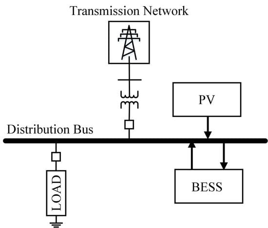
A simplified design of the distribution system with PV and BESS is presented in
Figure 1. In this study, three main models are integrated with the distribution system, which are photovoltaic systems, and battery energy storage systems and loads.
The increase installations of PV systems in the DNs have transformed the flow of electrical power to be more of a bidirectional flow instead of a fixed direction as the case of a radial configuration [
32]. Although this transformation of electrical power flow is beneficial from a technical and financial point of view, it also brings in a few technical challenges. One of the key challenges of utilizing solar PV systems is the uncertainty nature, which directly affects the system balance between demand and generated power. In such cases, the use of BESS is widely accepted as a feasible solution to provide or store electrical power as required [
33]. The placement of solar PV systems and BESSs at demand centers helps in reducing the current flow in DN; hence, energy losses are minimized. Nevertheless, the appropriate allocation of BESS into DN also has the potential to significantly further decrease the DN power losses. The aim of this paper is to find the optimal placement of BESS to mitigate the power losses using GA as an optimization technique. In order to exemplify the distribution network properly, the IEEE 33-Bus system was utilized as shown in
Figure 2.
As can be seen, the 33-Bus system is linked with 32 distribution lines, which has a power base of 10 MVA and 12.66 kV as a rated voltage. In addition, the active power and reactive power of the system load are 7.4 MW and 4.6 MVAR, respectively [
28]. The power grid is mainly supplying the required demand. In this study, the optimal allocation of PV systems is not considered, since its contribution toward power losses reduction as well as load leveling is less effective compared to BESS optimal allocation. Therefore, six PV systems each one is sized as 1.6 kW, which are installed arbitrary at six different DN buses utilized to supply active power.
The objective function is to minimize the power losses in the DN, which represented as follows:
The considered time interval is , where is the total time period considered. The is the conductance between buses i and j. The is total number of branches of the network. The voltage magnitudes of buses i and j are and , where the voltage angles of buses i and j are and .
Subjected to the following constraints
The minimum voltage magnitude for i buses is , whereas the maximum voltage magnitude for i buses is . The is the actual power flow, and the maximum actual power flow is .
3. Proposed Methodology
The proposed methodology contains three main sub-sections, which are system modeling, BESS modeling, and the description of GA as an optimization technique. The comprehensive mathematical system modeling of the considered portion of the DN in this study is described in the following subsections followed by the utilized optimization approach to specify the optimal locations of the energy storage systems assuring the minimum power losses in the DN.
3.1. System Modeling
The system model considered in this paper has two main models, which are the load model and solar photovoltaic model.
The first part is the load modeling, which is used to demonstrate typical loads in a distribution network. Generally, the electrical power is transmitted to load centers via distribution buses, which are fed from a power source network. In the IEEE 33-bus power system considered in this study, the area load has to be simplified and scaled to suit the testing model. In the proposed model, all parameters are estimated using online training based on real-time measurements to ensure that the model parameters are kept up to date to track the time-varying loads. In this paper, the power flow Forward-Backward Sweep (FBS) algorithm is used. Through the use of typical load profile, scaled values are utilized to generate 24 hours demands at each bus of the IEEE-33 bus system [
33].
The second part is the solar PV model, which expresses the PV generation plant behavior throughout the day. There are several factors that affect the PV model such as rated power, solar irradiance, and temperature. Moreover, the PV model can be represented and simplified as shown in
Figure 3.
The PV array model consists of series and parallel resistances and , series and parallel modules and , the output voltage and current and , and the module current source .
The current source of the module
can be expressed as follows:
The array thermal voltage , and the ideality constant of the diode .
The thermal voltage
can be represented as follows:
where,
is the number of series cells and
is the Boltzmann’s constant. The electron charge is
and
is the Kelvin temperature of the P-N junction.
The PV and reverse leakage currents
and
can be represented as in the following equations:
The PV nominal current is , and the temperature confident current and voltage are and respectively. The and represent the irradiance and the irradiance at nominal conditions, respectively. The nominal short circuit current is and the nominal open circuit voltage is . Finally, the is the difference between the actual and the nominal Kelvin temperatures.
Apparently, the PV generates power in the daytime. The output power of the actual single PV module is presented in
Figure 4. It is generated based on Dammam city solar irradiance which is measured in June of 2019. The maximum PV module output power is about 190 W at 12:00.
3.2. BESS Modelling
The model of the BESS includes the capacity of power charging and discharging, the energy capacity, and the efficiency of charging and discharging [
6]. Practically, the BESS model is a nonlinear model due to the difference between charging and discharging efficiency values. Thus, in this study, both charging and discharging efficiency values are considered to be identical in order to linearize the BESS model.
The BESS model can be expressed as in the following equation:
Subjected to the following constrains:
The storage level is , and the amount of stored or supplied power is . The charging and discharging efficiencies are and , respectively.
The main application of this study is the load leveling using the BESS to minimize the DN power losses. The basic principle of load leveling is to reduce load variation throughout the day. The load variation reduction could be achieved by increasing the generation amount during off-peak periods and store it to supply the demand during peak periods. Several utilities are challenged by the difference between low and high demand levels. Thus, the load leveling helps to maximize the revenue sale from the off-peak generated power during the peak demand times and reduce the need to operate generation units with low efficiency [
34,
35]. Furthermore, the traditional power systems generation and loads arrangement lead to significant total power losses. One of the promising solutions to avoid power losses is the load leveling to maintain a reasonable load variant [
36]. The adoption of BESS provides extra power dispatch elasticity and enables load leveling for longer periods. Usually, the BESS effectiveness in reducing power losses is subjected to the location, numbers and sizes of BESS used in the power system network [
37]. Therefore, the optimal BESS placement is needed to further reduce the power losses. The stochastic optimization GA is utilized in this study to find the optimal BESS placement in DN.
3.3. Genetic Algorithm
The optimal solutions of the latest sophisticated problems are achieved using evolutionary optimization algorithms like the GA, Tabu search (TS), differential evolution (DE), and particle swarm (PS) [
38]. Genetic Algorithms (GA) are well known evolutionary approaches which commonly employed to find the optimal solutions of the non-linear problems. These algorithms are stochastic searching algorithms that start with the initial population and process it through many iterations to find the optimal solution. It is uniquely simple, robust and known as a quick conversing method [
39].
Generally, the GA formulation contains many elementary optimization parameters and operations such as generation (
G), population size, objective function, selection, crossover parameter and probability, and mutation parameter and probability, which require a specific setting depending on the intended optimization problem [
40]. They affect the GA output accuracy and processing duration. Hence, they should be chosen precisely. The main GA operations to generate a new population (
Pnew) of possible solutions (
Xi) are the crossover and mutation. These operations are controlled by crossover and mutation probabilities (
α,
µ). The crossover is the next operation after the selection operation, where two random possible solutions (
Xm,
Xn) are selected from the current generation (
Gk). The possible solution has an upper limit (
Xmax) and a lower limit (
Xmin). The goal of the crossover operation is to generate two new solutions (
Xmd,
Xnd), which are better than their original solutions for next generation (
Gk+1), as shown in (11) and (12). However, the GA might be trapped in local minima or local maxima that required a special operation to take it out. Thus, the mutation operation is the operation that will do this task as shown in (13) and (14), where
γ and
σ are random numbers between 0 and 1.
Several GA approaches have been utilized in recent studies such as [
7,
15,
29]. It indicates and highlights the high effectiveness of the GA compared to other stochastic approaches that are based on the error percentage of the solution and the processing duration.
Figure 5 illustrates the utilization of GA to find the optimal allocation of BESS.
In this study, the DN data and the BESSs data are fed as inputs to the GA. The input data has been processed through many iterations and GA internal operations. The resultant of the GA processing is the optimal locations of the BESSs in the DN which assure the minimum average power losses.
4. Results and Discussions
To validate the proposed technique in this paper, the IEEE 33-Bus system has been utilized as a case study and incorporated the provided data in [
33]. The system is linked with the utility grid via a transmission line with limited capacity. The presented work contains four cases that have been simulated using MATLAB software. The focus of this work was the total power losses reduction in DN. Starting with the reference case study, which is used to compare the improvements before and after the addition of the solar PV systems, an aggregated BESS or distributed BESSs. Hence, the reference case demonstrates the DN with no solar PV systems and BESS. This case is used as a reference while comparing the total power losses reduction in all considered cases. Then Case-I considers only PVs in place. After that, Case-II includes solar PVs and an aggregated BESS. Finally, Case-III comprises solar PVs and distributed BESSs. A detailed description of each case is presented as per the following subsections:
4.1. Distribution System with Solar PVs: Case-I
Six solar PVs, each with a size of 1.6 kW, are added arbitrary in the distribution network, as shown in
Figure 6. This case demonstrates DN with a high level of PV penetration. The PVs are installed on buses 3, 8, 14, 25, 30, and 31.
Figure 7 and
Figure 8 show the system load profile for a one day selected from the winter season as minimum and another day from summer season as maximum, respectively. The actual load profile of Dammam city (Saudi Arabia) on 2 January 2019, is recorded as the minimum daily load profile throughout the year 2019, as shown in
Figure 7. During the selected minimum daily load profile, the load varies from 6300 kW at 08:00 to reach to 7400 kW at 19:00. On the other hand, the actual load profile of Dammam city (Saudi Arabia) on 5 September 2019, is documented as the maximum daily load profile of 2019, as shown in
Figure 8. During the selected maximum daily load profile, the load varies from 6500 kW at 07:00 to 7400 kW at 14:00.
From the contrast of
Figure 4 against
Figure 7 as well as
Figure 8, it can be noticed that the PV model has a maximum output power that is not corresponding to the maximum load profile. Apparently, this mismatch leads to a huge limitation on the penetration magnitude as of which PV can supply power to DN. One of the promising solutions for this limitation is to utilize the ESS solution such as BESS. With the use of BESS, it is possible to store power when demand is low and then supply power back when demand is high. Nevertheless, the BESS is a key enabler for proper management of load leveling including DNs.
4.2. Distribution System with Solar PVs and an Aggregated BESS: Case-II
Aggregated BESSs are widely used in DNs for ancillary services. However, the BESS proper allocation plays a significant role in maximizing the benefits from aggregated BESS installment. Hence, GA optimization technique is used to optimally allocate the aggregated BESS within the considered IEEE 33-Bus system, as shown in
Figure 9.
As shown above, there are six solar PV systems installed in the following buses 3, 8, 14, 25, 30 and 31. The placement of PVs has been carried out in a similar manner as of case-I. However, with the utilization of GA, the aggregated BESS is optimally allocated and installed on bus 14. The size of the aggregated BESS is 0.7 kWh.
Figure 10 and
Figure 11 demonstrate the system load profile comparison with and without an aggregated BESS. It can be observed in
Figure 10 that the demanded load has been leveled up at 6900 kW from 02:00 to 10:00. In addition, the demanded load has been leveled down at 7100 kW from 17:00 to 21:00. Similarly, it can be seen in
Figure 11 that the demanded load has been leveled up at 7000 kW from 00:00 to 10:00. Also, the demanded load has been leveled down at 7200 kW from 11:00 to 20:00. Overall, the load profile with BESS provides flexibility for the system operators and increases the utilization factor of the solar PVs.
4.3. Distribution System with Solar PVs and Distributed BESSs: Case-III
The case-III shows the DN with a high level of PV penetration along with distributed BESSs. It is represented in the IEEE 33-Bus with PV and distributed BESSs, as shown in
Figure 12. Similarly, the GA optimization technique is used to optimally allocate the distributed BESSs within the considered system. As shown below, there are six solar PV systems installed in the following buses 3, 8, 14, 25, 30 and 31. The placement of PVs has been carried out in a similar manner as of case-I. Whereas, the six distributed BESSs are optimally allocated and connected to the following buses 8, 14, 24, 25, 30, and 31. The size of each distributed BESS is 0.11 kWh, which is almost one sixth times the aggregated BESS.
In contrast,
Figure 13 and
Figure 14 represent an individual bus load with a single distributed BESS and a single PV system. By considering one day duration, the charging of the BESSs starts during the low demand period and discharging the stored energies back during the high demand period. It can be observed in
Figure 13 that the demanded load has been leveled up at 222 kW from 02:00 to 10:00. Moreover, the demanded load has been leveled down at 230 kW from 17:00 to 21:00. Likewise, it can be seen in
Figure 14 that the demanded load has been leveled up at 222 kW from 01:00 to 09:00. In contrast, the demanded load has been leveled down at 230 kW from 11:00 to 21:00. The presented load profiles with distributed BESSs provide more flexibility for the system operators as it reduces the power flow within the DN. Besides, it helps to increase the solar PVs’ utilization factor.
The use of BESS helps to achieve huge improvements in energy management through the practice of load leveling, as demonstrated in
Figure 10,
Figure 11,
Figure 13 and
Figure 14. It can be seen that the demand valley has been filled during the low demand period and power was injected during the high demand period. Hence, the generated power from the solar PV systems is now properly utilized. In addition, the numbers of committed generation units are reduced, which provides the DN with more flexibility. Hence, the necessity for new power generation and transmission lines is minimized. The power losses reductions for the considered cases in this paper are summarized in
Table 1.
There are four cases considered in this study as illustrated in
Table 1; starting with a reference case that represents the DN without PV systems installation or BESS availability. Then, we consider the case when only solar PV systems are connected to the DN. Next, the optimal allocation of an aggregated BESS case and a distributed BESSs case were considered to investigate the technical feasibility to mitigate DN power losses via BESS. The average power losses between winter and summer are provided in each case in kWh. However, the discussion focuses on the annual average, especially the percentage of the total power losses reduction.
In the PVs Case-I, where only solar PVs are installed in DN, the total power losses in the annual average have been reduced by 35.36%. This substantial amount of total power loss reduction is the result of having less power flow between distribution lines since the power supply is now placed near to load centers. Hence, the installation of solar PVs in DNs is a key solution to reduce DN power losses. In fact, this solution is obviously more viable when combined with the BESS solution. However, the question is which configuration strategy of the BESS (e.g., centralized or decentralized) is more feasible in terms of maximizing the contribution toward DN power losses reduction.
The investigation started with an aggregated BESS along with the six installed solar PV systems in DN named PVs and Aggregated BESS Case-II. This case reduces the average power losses by 40.51%, which illustrates additional improvements in minimizing the load flow between the DN buses. However, the reduced percentage of power losses compared to Case-I is only 5.15%. Therefore, this case study shows improvement in power losses reduction, but the aggregated configuration of BESS has a relatively insignificant contribution to the total power losses reduction.
On the other hand, in the PVs and Distributed BESSs Case-III, six distributed BESSs are installed in the DN along with six solar PV systems. The distributed configuration of BESSs has resulted in a 57.68% reduction of the DN average power losses. The power losses reduction is also due to minimizing the load flow between the DN buses which in turn reduces power losses in the DN. Case-III provides the highest percentage of power losses reduction with an improvement of 17.17% when compared to Case-II, and 22.32% when compared to Case-I.
After the conducted case studies, Case-I with only solar PV systems showed promising performance in reducing the DN power losses; in Case-II with the addition of an aggregated BESS a slight improvement has been noticed. Clearly, the highest attained reduction of the total power losses is found to be in Case-III with the distributed BESSs configuration combined with solar PV systems.


