Application of a Superconducting Fault Current Limiter to Enhance the Low-Voltage Ride-Through Capability of Wind Turbine Generators


Department of Electrical Engineering Soongsil University, Seoul 06978, Korea
*
Author to whom correspondence should be addressed.
Energies 2019, 12(8), 1478; https://doi.org/10.3390/en12081478
Submission received: 13 March 2019
/
Revised: 7 April 2019
/
Accepted: 12 April 2019
/
Published: 18 April 2019
Abstract
:The penetration of wind turbine generators onto the grid has grown worldwide at unprecedented rates in recent years. This raises the concern that the tripping of wind turbine generators could potentially cause system collapses. To alleviate these concerns, wind turbine generators need to maintain connection with the grid when a grid fault occurs. This has provoked many countries to adopt low-voltage ride-through (LVRT) for wind turbine generators. The LVRT is the capability of wind turbine generators to maintain connectivity during certain periods of voltage sag. The wind turbine generators should be connected to the grid to support fault recovery. Also, wind turbine generators must provide reactive power according to the grid voltage sag. Therefore, much research has been focused on enhancing LVRT capability. To enhance LVRT capability, this paper proposes the application of a superconducting fault current limiter (SFCL) in the system. The fault current was suppressed and the voltage sag was improved through the application of the SFCL. By improving the voltage sag, the wind turbine generator and the grid were able to maintain a connection. However, suppression of the fault current can cause a problem in the overcurrent relay (OCR) trip time delay. The trip time delay was solved by OCR resetting. Through a power system computer-aided design/electromagnetic transients including DC (PSCAD/EMTDC), the enhancement of LVRT capability and improvement of the trip delay was confirmed.
1. Introduction
Over the past few years, wind power, as a source of renewable energy, has grown rapidly in many countries [1]. The significant increase in the capacity of wind farm has led to concerns about grid stability. Until now, the traditional wind turbine generators connected to the grid were usually disconnected when grid faults occurred. In practice, the tripping of wind turbine generators caused a power outage in Western Europe due to 4892 MW losses [2]. This case shows that when wind turbine generators are tripped, the system can collapse. Therefore, there is a grid code to alleviate concerns about these problems.
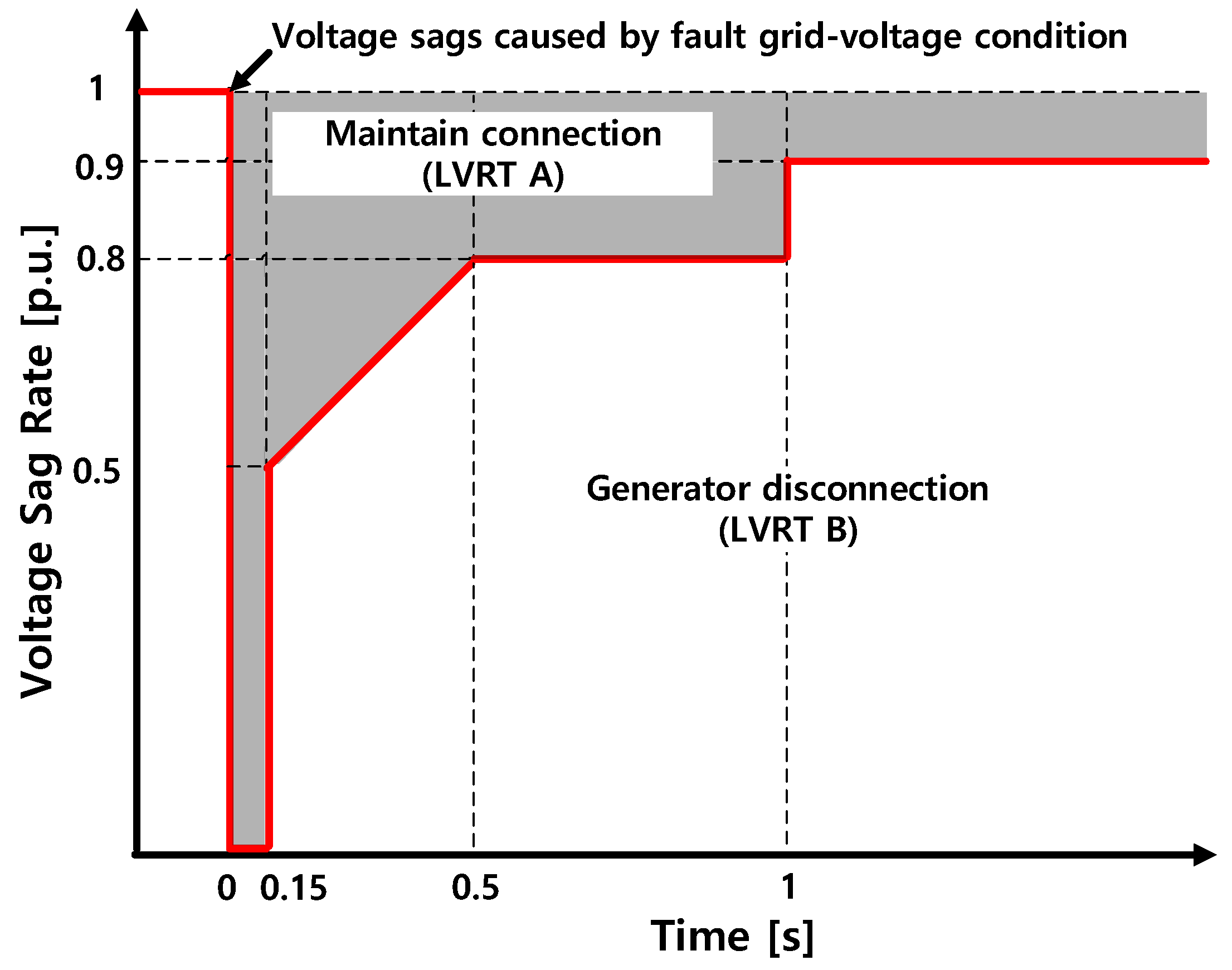
One of the important issues in the grid codes is the low-voltage ride-through (LVRT). The LVRT is the capability to maintain the connection between the wind farm and the grid for short periods of the time. Figure 1 shows the LVRT requirement in Korea. The x-axis is time and the y-axis is the highest value of three-phase line-to-line grid voltage at the point of common coupling (PCC). In case of the fault corresponding to area A, the wind turbine generators must maintain the connection with the grid. In case of the fault corresponding to area B, the wind turbine generators and the grid can be disconnected. However, the wind turbine generators and the grid must resynchronize within two seconds after fault removal. Also, the wind turbine generators must supply active power to the grid at 10% of the rated capacity per second. In the event of the fault corresponding to area C, the wind turbine generators and the grid are disconnected [3,4,5].
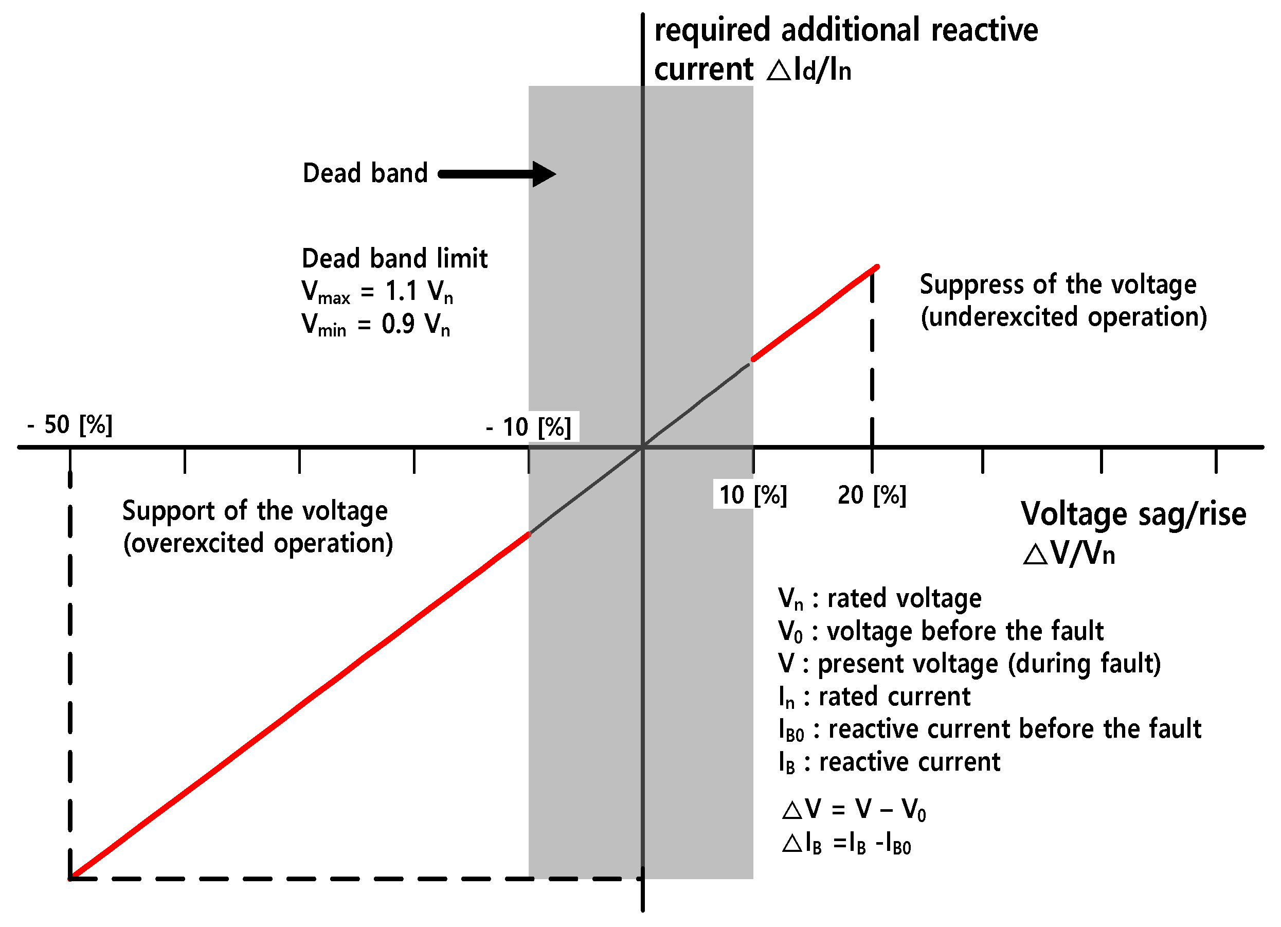
The wind turbine generators should support the grid by providing reactive power during a grid fault. Figure 2 shows the reactive power requirement according to the grid voltage sag. Reactive power is not required in the dead band considered normal operation. When the grid voltage is out of the normal range, the wind turbine generators must supply reactive power to the grid according to the voltage sag rate [3,4,5].
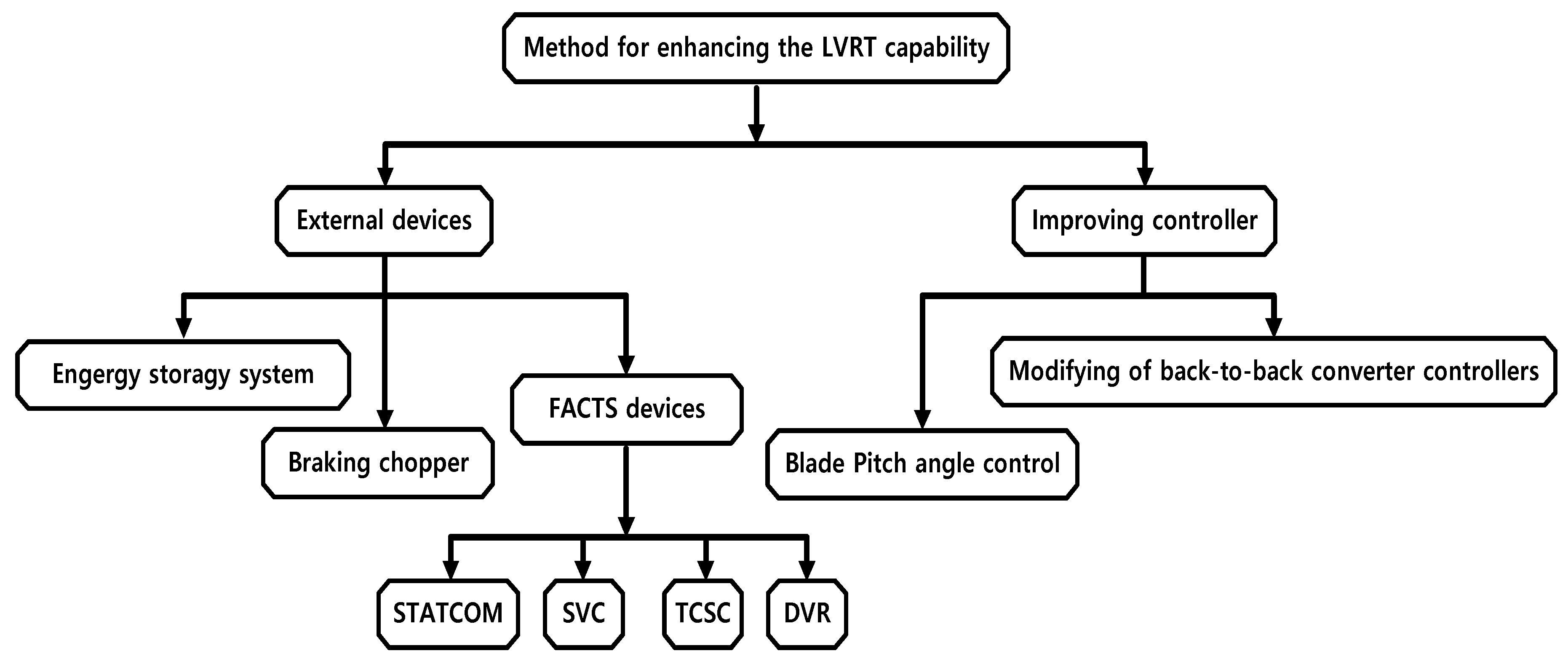
The purpose of enhancing LVRT capability is to maintain the connection between the wind turbine generator and the grid for recovery of the fault voltage. Through connection maintenance, system operators and customers can improve the system’s stability and power generation companies can increase their profits by increasing the power generation volume. For the above reasons, much research has been carried out to enhance LVRT capability. As shown in Figure 3, in terms of enhancing LVRT capability, there are two methods: external devices and modified controls [6,7].
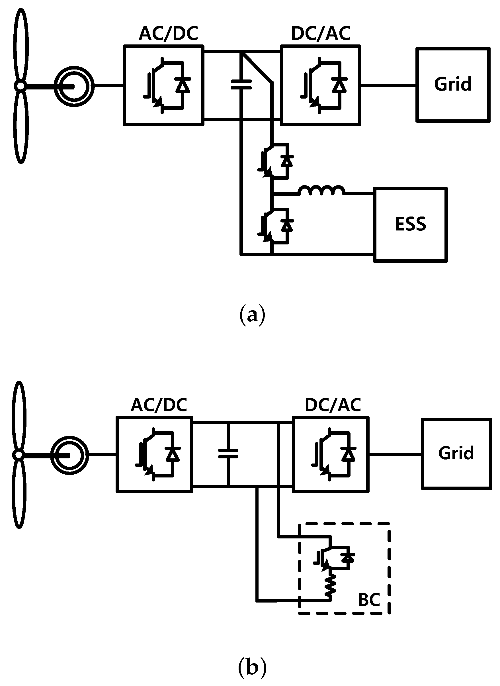
The energy storage system (ESS) can be connected to the dc-link of a wind generator, as shown in Figure 4a. When a grid fault occurs, the ESS can absorb the surplus energy from the dc-link and prevent overvoltage. After fault clearance, the stored energy is injected into the grid [8,9,10]. The breaking chopper (BC) is composed of high-power resistors with a series switch, as shown in Figure 4b. In the event of a grid fault, overvoltage is prevented by eliminating excess power by unbalance. The BC has the advantage of being a low-cost and simple control structure. However, since it can not contribute to reactive power injection into the grid, it is used in combination with other controls [11,12]. The flexible AC transmission system (FACTS) supplies the reactive power to compensate for the voltage sag [13,14]. The pitch angle control (PAC) controls the pitch angle of the blades to limit the output by reducing the captured power. The wind turbine generator can perform power smoothing thorugh the PAC. However, the PAC has a slow response due to mechanical characteristics [15,16]. The back-to-back (BTB) converter control maintains the DC voltage and implements maximum power point tracking (MPPT). However, when a grid fault occurs, the converter may be out of the control [12,17,18].
The conventional methods mentioned in Figure 3 have disadvantages such as high cost and vulnerability to faults. In addition, the BC and the FACTS should be combined with other methods. In particular, conventional methods focus on protecting the wind turbine generator, maintaining the DC voltage, and supplying reactive power [6,7]. Since the disconnection of a large-capacity wind farm causes system collapse, it is necessary to maintain the connection between the wind farm and the grid through the improvement of the voltage sag [2,3,4,5]. Therefore, this paper proposes the application of superconducting fault current limiters (SFCLs) to the grid to maintain the connection between grid and wind turbine generator. By applying an SFCL to the outgoing point of the feeder, it is possible to obtain not only the suppression of the fault current but also the improvement of the voltage sag. Improved voltage sag using an SFCL can enhance the LVRT capability. The wind farm and grid can maintain connection through enhancing LVRT capability. To confirm the effect of the suggested method, a power system computer-aided design/electromagnetic transients including DC (PSCAD/EMTDC) simulation was conducted. Section 1 describes previous research and the need for this paper. Section 2 describes the system modeling for the simulation. Section 3 verifies the proposed method through simulation. Section 4 is the conclusion of this paper.
2. Simulation Modeling
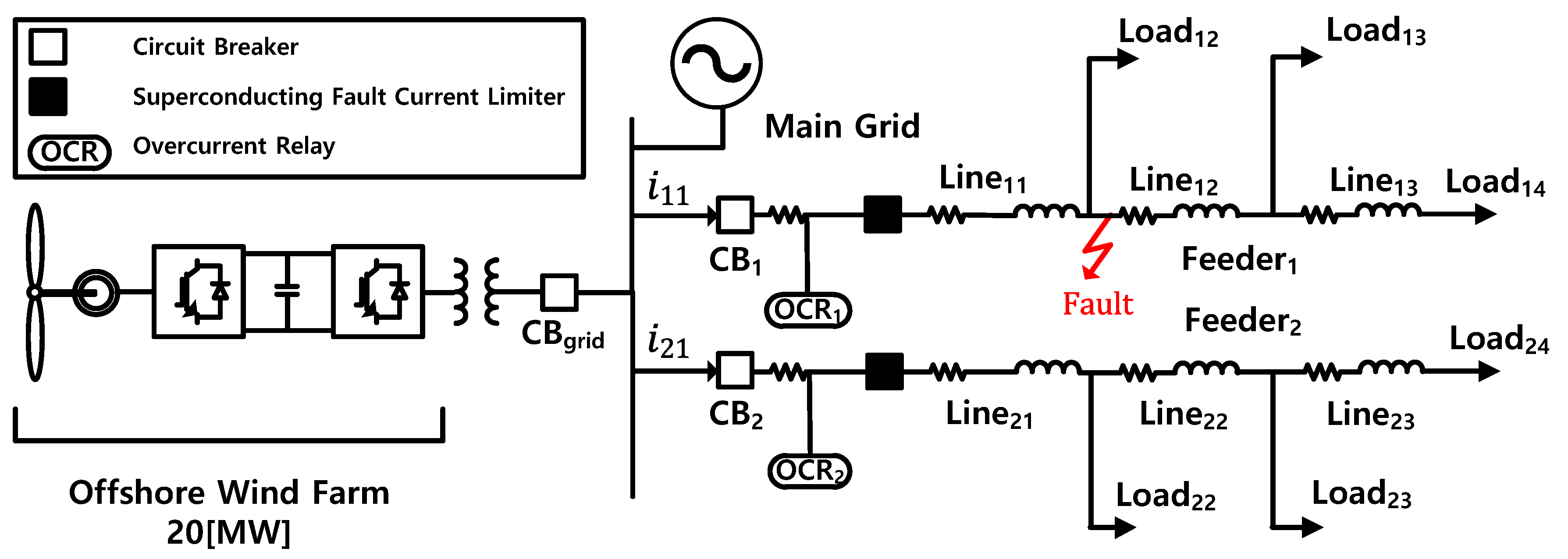
The modeling involved connecting an offshore wind farm and grid as shown in Figure 5. The SFCL was installed at the outgoing point of the feeder. The system and wind power generator parameters are listed in Table 1 and Table 2, respectively. The fault scenarios used in the simulation is shown in Table 3.
2.1. Superconducting Fault Current Limiters
Section 2.1 describes the modeling of the SFCL. There are various types of SFCL, such as the magnetic shielding type, bridge type, saturable core type, and trigger current level type. Among them, the trigger type is advantageous as the burden on the high-temperature superconducting (HTSC) can be reduced and the configuration is simple. Therefore, the trigger type is the most practical and economical. All recent trials in field tests in the last five years have been performed using the trigger type. Furthermore, all SFCLs operated in 2017 are of the trigger type. This implies that the trigger type has more technological advantages than the other SFCL types [19]. The trigger-type superconducting fault current limiter (T-SFCL) used in this paper was based on experiments in the Korean distribution system.
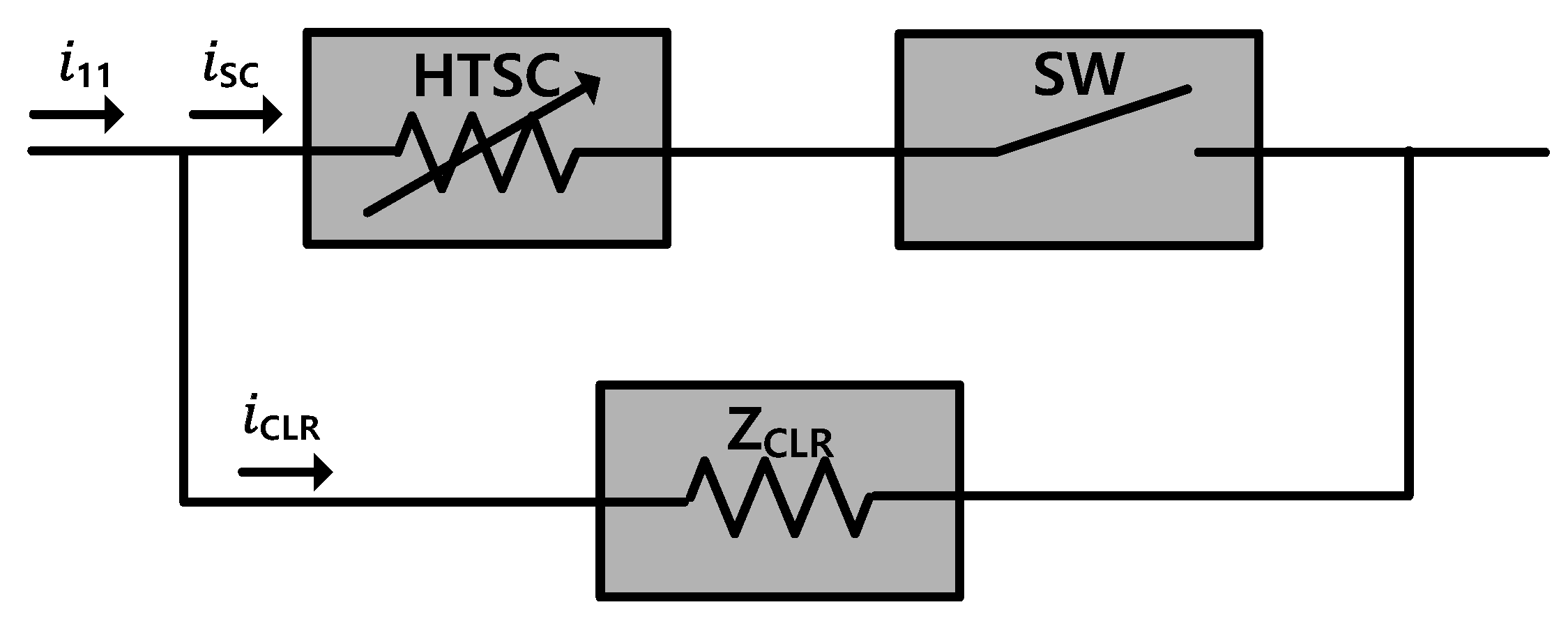
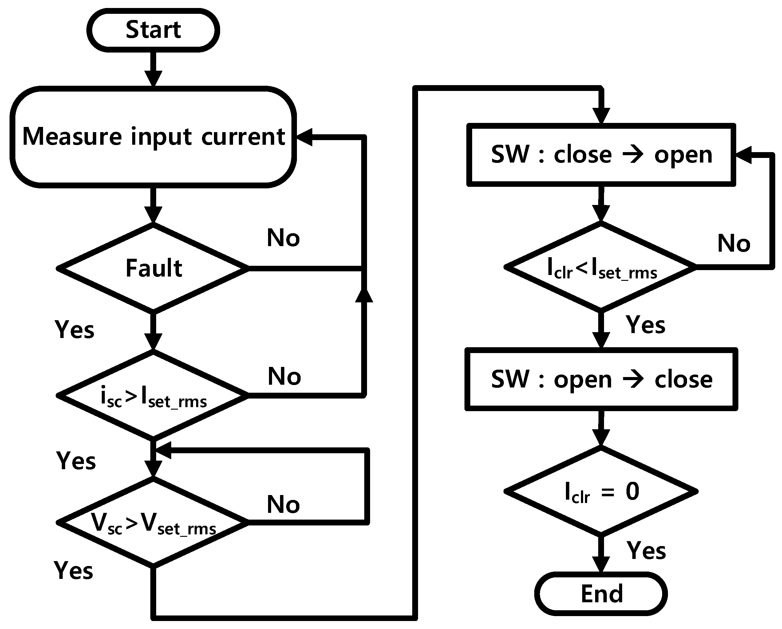
Figure 6 shows the T-SFCL. The T-SFCL consists of the HTSC (high-temperature superconducting), the current limiting reactor (CLR), and the switch (SW). In the normal state, the resistance of the HTSC is zero, so there is no effect on the system. If the fault current exceeds the threshold value, the HTSC has resistance due to quenching phenomenon [20,21,22]. Figure 7 show the operating sequence of the T-SFCL. Table 4 shows the parameters of the SFCL.
The impedance of the HTSC according time is Equation (1). The is impedance being saturated with normal temperature. The represents a time constant. The , and represent quench starting time, first recovery starting time, and secondary recovery starting time, respectively. The , and represent the coefficients of experimental result of the recovery characteristics of the SFCL [20,21,22].
When the SFCL is applied to the grid, it has the following advantages:
- In the normal state, the SFCL has no resistance. Therefore, it does not affect the grid and there is no line loss.
- When the fault current exceeds the threshold, the SFCL has impedance. Therefore, it is possible to suppress the fault current before reaching the peak. Thus, the upgrading cost of the circuit breaker can be reduced.
- In the event of a grid fault, the impedance increases due to the quenching phenomenon. Therefore, the voltage sag is improved.
- When the fault current is below the threshold, the SFCL is recoverd to the normal state.
- The SFCL quenching phenomenon depends on the threshold.Therefore, even if the fault current magnitude increases due to grid configuration changes, the SFCL does not need to be replaced.
To improve the voltage sag, the SFCL was applied to the outgoing point of the feeder as shown in Figure 5. Equation (2) shows the PCC voltage when the SFCL was installed on the outgoing point of the feeder. When a grid fault occurs, the voltage sag is improved because the impedance was increased by the SFCL [21,22].
2.2. Overcurrent Relay
Korea’s overcurrent relays (OCRs) are generally inverse time characteristics about the magnitude of the fault current and the trip time. Equations (3) and (4) show the trip signal time and M index. A, B, K, and p are the constants. and are the time lever and current tap. Table 5 shows the parameters of the OCR.
As mentioned in Section 2.1, the SFCL suppresses the fault current according to the quenching phenomenon. Therefore, the trip time delay problem can occur due to the inverse time characteristics of the OCR. In Section 3, the problem of trip time delay was confirmed and resolved by resetting the OCR [23,24].
3. Simulation Results
3.1. Case without SFCL
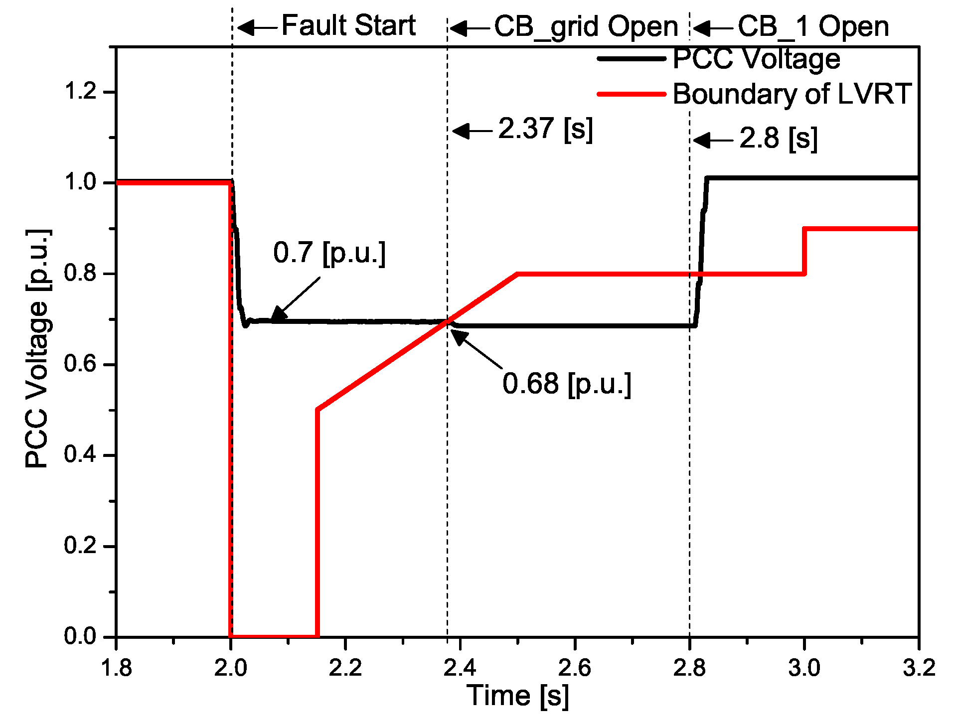
In Section 3, the effect of installing the SFCL to enhance the LVRT capability is confirmed through PSCAD/EMTDC simulation. Figure 8 show the PCC voltage without an SFCL. In the event of a fault, the PCC voltage sags to 0.7 p.u. At 2.37 s, corresponding to the LVRT B area, the PCC voltage sags to 0.68 p.u. due to disconnection of the offshore wind farm from the grid. At 2.8 s, the PCC voltage returns to the normal state by clearing the fault feeder.
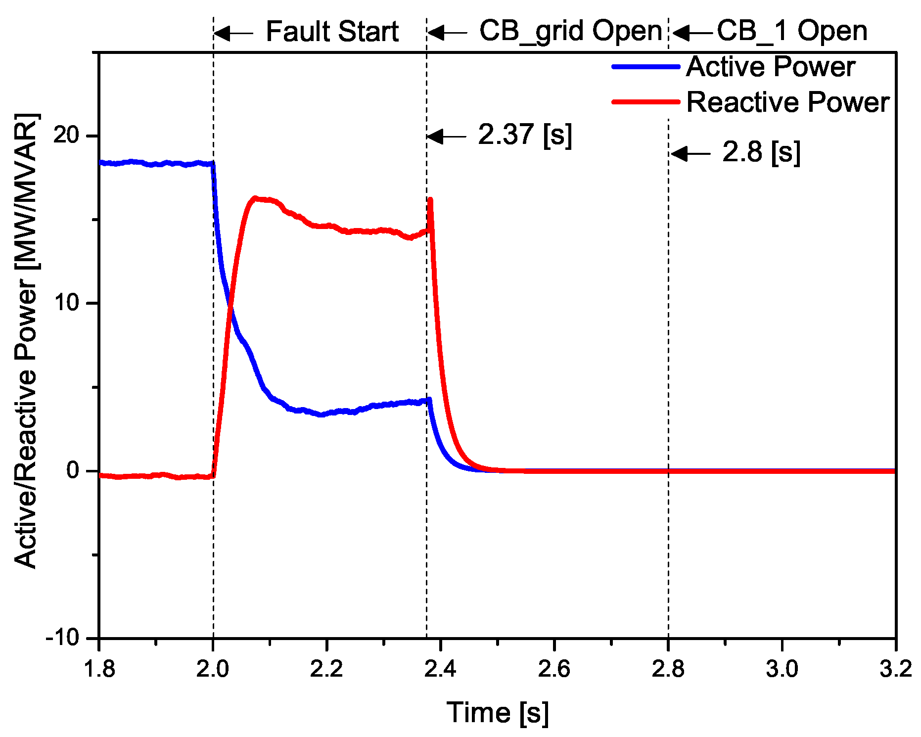
Figure 9 shows the active power and reactive power output of the offshore wind farm. In the event of a grid fault, the reactive power output increases to recovery the grid voltage. The reactive power output must meet certain conditions, as shown in Figure 2. Depending on the capacity of the converter, the active power output decreases as the reactive power output increases. At 2.37 s, the offshore wind farm and the grid are disconnected because the wind farm corresponds to the LVRT B area. The disconnection of the grid and the offshore wind farm causes problems such as a decrease in the power generation volume and a decrease in stability.
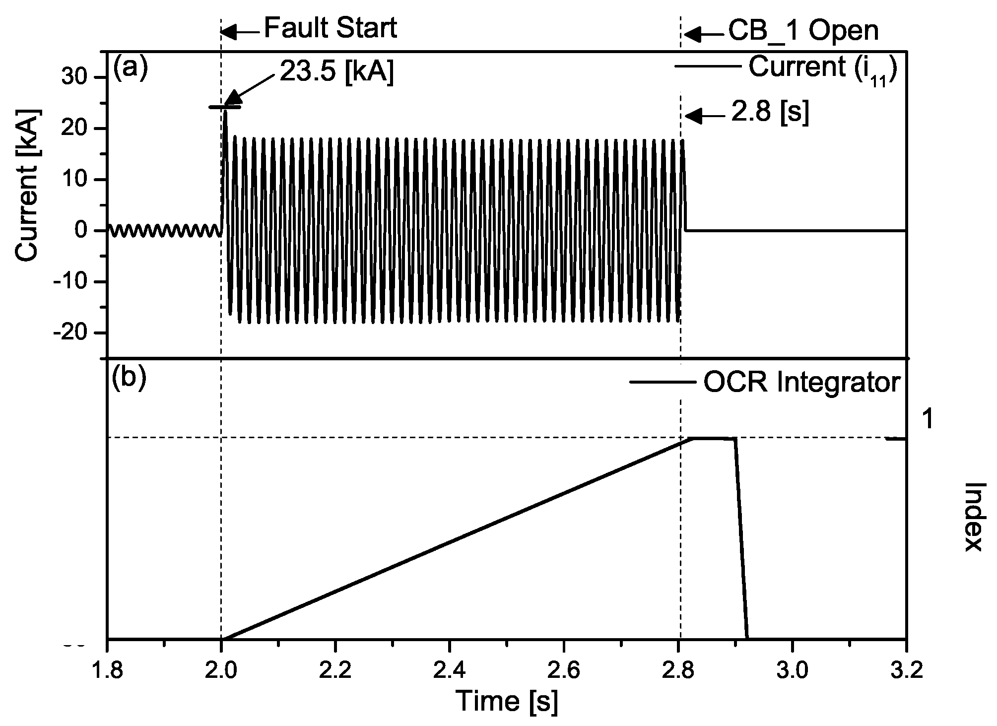
Figure 10 shows the feeder current and trip signal of the OCR. When a fault occurs in the grid, the fault current increases to 23.5 kA. The faulted feeder was cleared due to the trip signal at 2.8 s.
At 2.77 s, the wind farm was disconnected by a fault corresponding to the LVRT B area. At 2.8 s, the faulted feeder was cleared and PCC voltage returned to a normal state. The disconnection of the wind farm and the grid means a decrease in system stability and economic loss. Therefore, Section 3.2 analyzes a method to enhance the LVRT capability through the application the SFCL.
3.2. Case with an SFCL
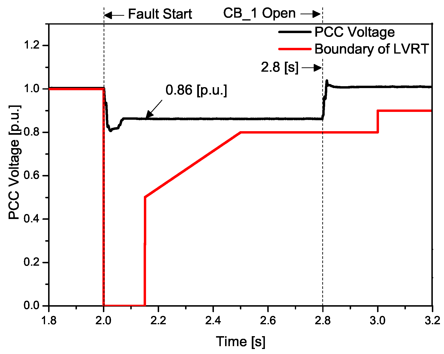
In Section 3.2, an SFCL was applied to improve the PCC voltage sag. The improvement of the PCC voltage sag means enhancing LVRT capability. Figure 11 shows the PCC voltage with an SFCL. In the event of a grid fault, the PCC voltage sags to 0.86 p.u. Compared to the case without an SFCL, the connection time of the offshore wind farm and the grid has been increased. However, at 3 s, the offshore wind farm and the grid were eventually disconnected.
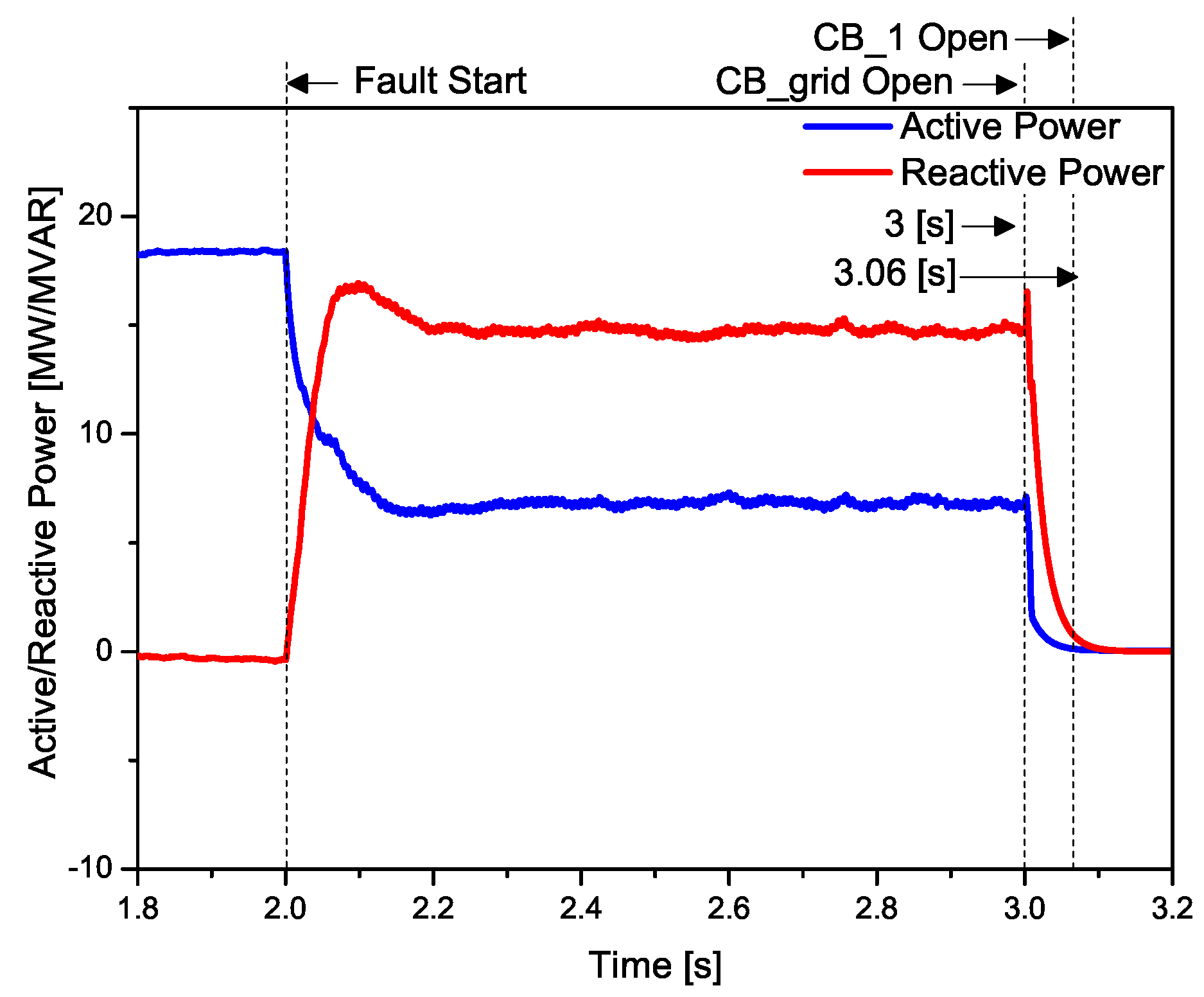
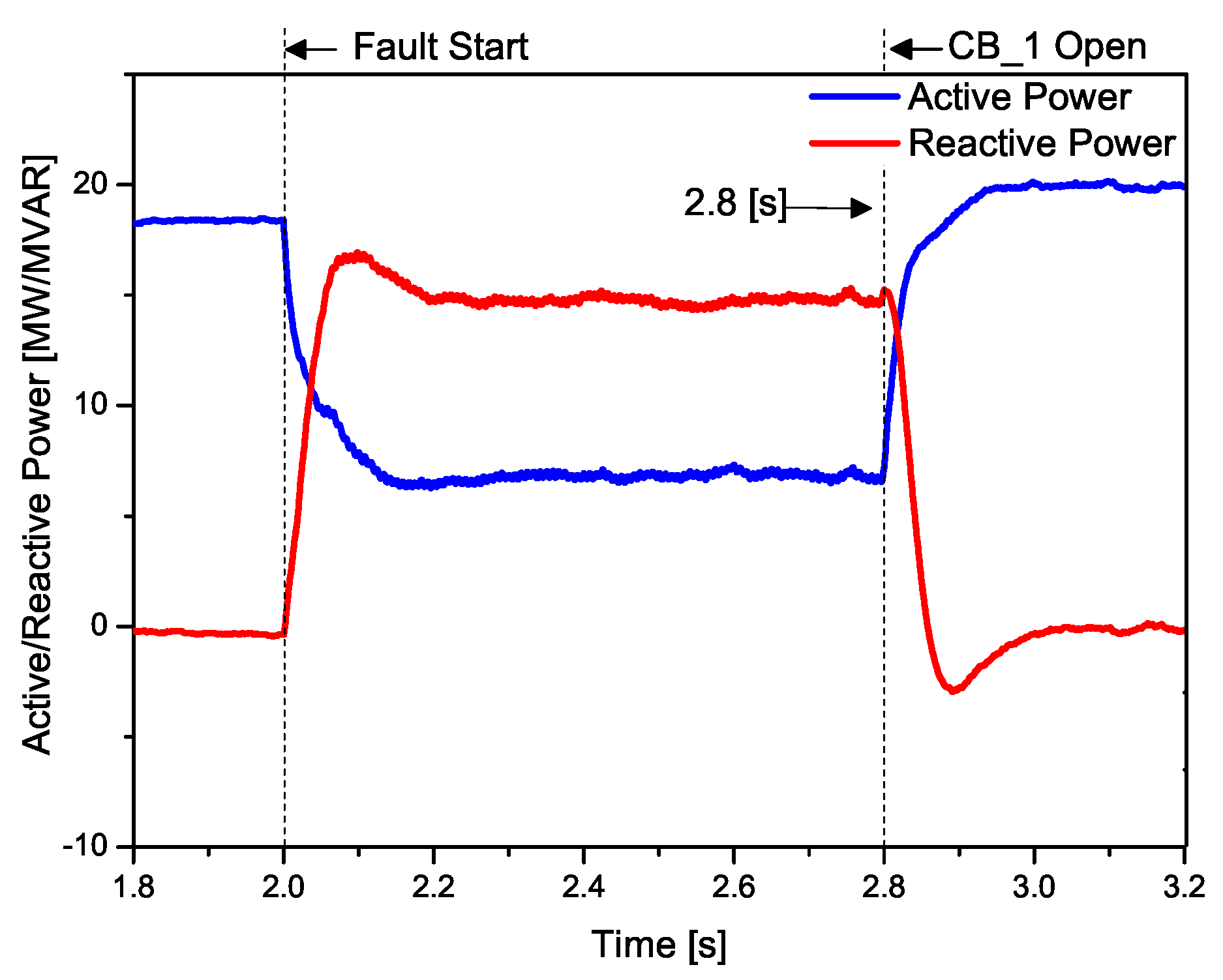
Figure 12 shows the offshore wind farm output with an SFCL. The generation volume of the offshore wind farm was increased due to the increased connection time compared to the case without an SFCL. Moreover, the wind turbine generators contribute to the recovery of the grid voltage, thereby improving the stability of the system. However, due to the clearing of the faulted feeder being delayed, the wind farm was eventually disconnected at 2.95 s.
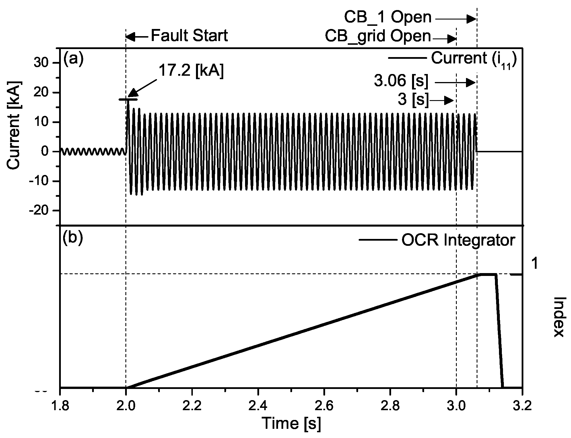
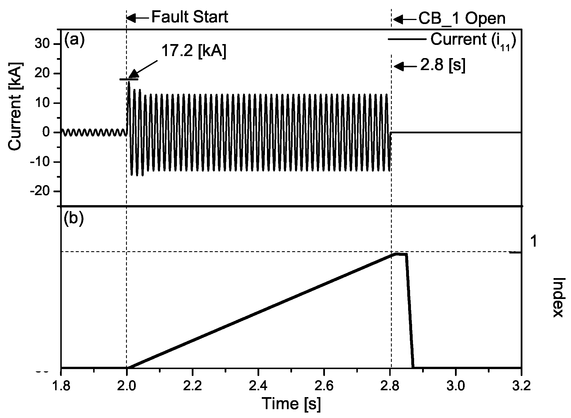
Figure 13 shows the fault current of the feeder and trip signal with the SFCL. When the grid fault occurs, the fault current was reduced by 17.2 kA compared to the case without an SFCL. However, the trip signal was delayed due to the decrease in the fault current. Therefore, the trip time delay should be improved through OCR resetting.
3.3. When the OCR Is Reset, Case with an SFCL
As noted in Section 3.2, the application of an SFCL improves the connection time and voltage sag. In addition, the fault current was suppressed through the SFCL. However, the trip time was delayed due to the suppression of the fault current. As a result, fault feeder clearance was delayed and the offshore wind farm and grid were eventually disconnected. In Section 3.3, OCR resetting was analyzed to solve the trip time delay.
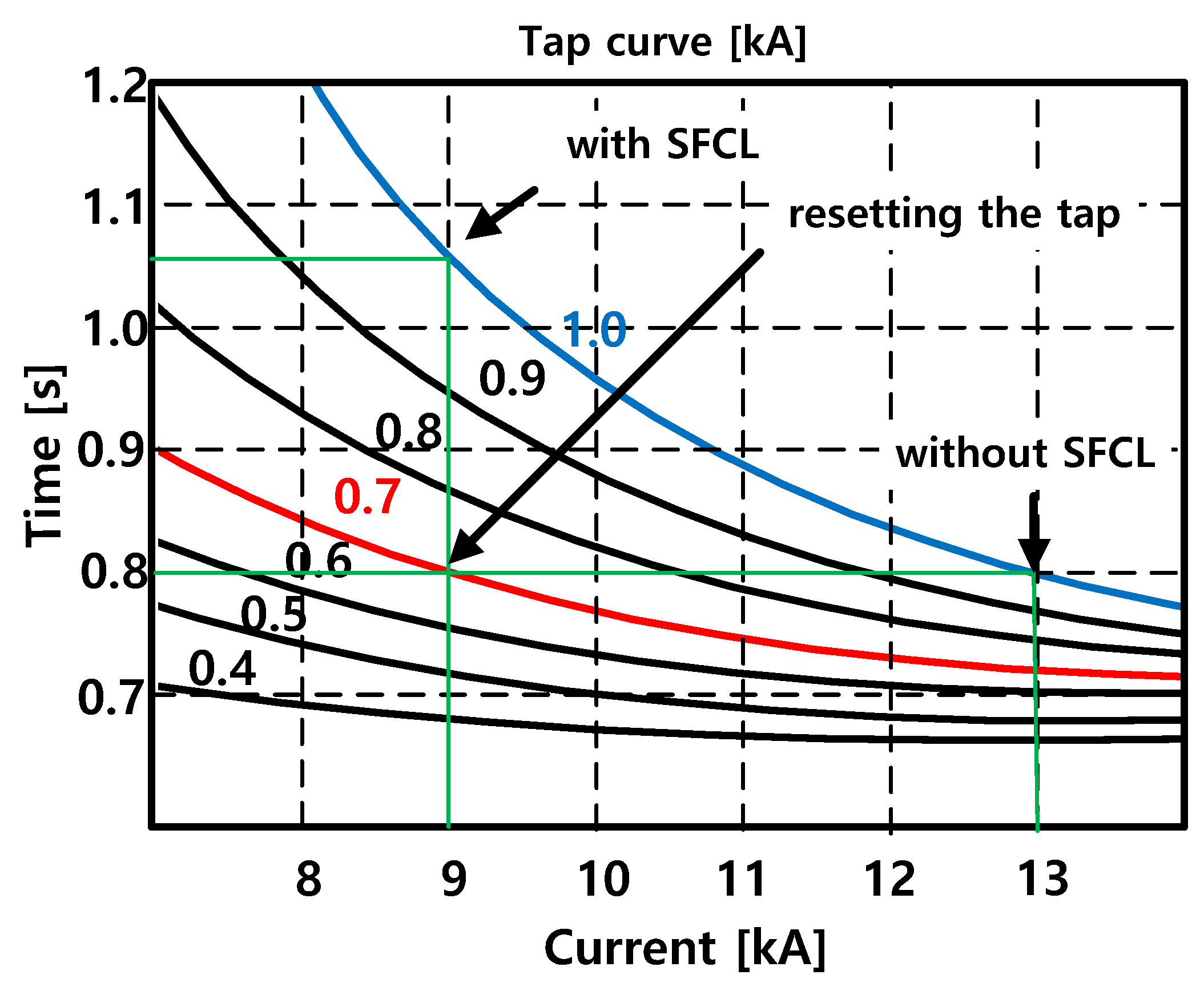
The method of resetting the OCR is to change the tap. The method of changing the tap maintains the existing trip signal time by suppressing the changing of the M index. Figure 14 shows the operation time–current graph of the OCR according to the changing of the tap. When the SFCL was applied, the trip time of the OCR increased to about 0.2 s in the conventional tap 1 kA curve. Thus, the tap of the OCR was changed from a 1 kA curve to a 0.7 kA curve to maintain the existing trip time.
Figure 15 shows the PCC voltage when the OCR is reset. In the event of a grid fault, the PCC voltage sags to 0.86 p.u., as in the case of SFCL application. The removal time of the faulted feeder was similar to before the SFCL application.
Figure 16 shows the output of the offshore wind farm when the OCR is reset. At 2.8 s, the output of offshore wind farm returns to the normal state at 2.8 s by improving the trip time delay. The system stability and economy has been improved through maintaining the connection between the offshore wind farm and the grid.
Figure 17 shows the fault current of the feeder and the trip signal when the the OCR was reset. The fault current was suppressed and the trip time delay was improved.
3.4. Discussion
This paper proposed the application of an SFCL to enhance LVRT capability. In order to enhance LVRT capability, the voltage sag was improved to maintain the connection between the wind farm and the grid. As a result, the LVRT area was changed and the connection between the offshore wind farm and the grid was maintained. However, the trip time was delayed because of the decrease in the fault current. The tap of the OCR was changed to solve the trip time delay problem. Table 6 shows the PCC voltage, trip time per CB, and peak current according to the particular case simulated.
4. Conclusions
As the capacity of the wind farms increases, the LVRT becomes one of the most important codes. Therefore, much research has been done to enhance LVRT capability. However, the conventional method has focused on protecting the wind generators, has to be combined with other methods, and has the disadvantage of a high cost. This paper proposed the application of an SFCL to maintain the connection between wind farm and grid by enhancing LVRT capability. The impedance was increased through the installation of the SFCL on the feeder of the grid so that the voltage sag was improved. When the voltage sag was improved, the LVRT area was changed, so the wind farm and the grid maintained their connection. The proposed method has the following advantages:
- The voltage sag is improved through the application of the SFCL. This maintains the connection between the wind farm and the grid through enhancing LVRT capability.
- System stability is improved because the wind farm contributes to the recovery of the voltage.
- The generation volume is increased because the connection between wind farm and grid was maintained.
- The fault current peak is suppressed by applying the SFCL.
The suppression of the fault current can cause a trip time delay problem; however, this paper confirmed that the problem can be solved through the resetting of the OCR.
Author Contributions
Methodology, S.-H.L.; Writing-original draft, H.-J.L.; Writing-review and editing, J.-C.K.
Funding
This research was supported in part by the Korea Electric Power Corporation (Grant number: R18XA04).
Acknowledgments
This research was supported in part by the Korea Electric Power Corporation (Grant number: R18XA04).
Conflicts of Interest
The authors declare no conflicts of interest.
References
- Mohseni, M.; Islam, S.M. Review of international grid codes for wind power integration: Diversity, technology and a case for global standard. Renew. Sustain. Energy Rev. 2012, 16, 3876–3890. [Google Scholar] [CrossRef]
- Maas, G.A.; Bial, M.; Fijalkowski, J. Final Report-System Disturbance On 4 November 2006. Tech. Rep. Union for the Coordination of Transmission of Electricity in Europe, 2007. Available online: https://www.entsoe.eu/fileadmin/user_upload/_library/publications/ce/otherreports/Final-Report-20070130.pdf (accessed on 18 April 2019).
- E.ON Netz. Grid Code High and Extra High Voltage; E.ON Netz: Bayreuth, Germany, 2006. [Google Scholar]
- Erlich, I.; Bachmann, U. Grid code requirements concerning connection and operation of wind turbines in Germany. In Proceedings of the IEEE Power Engineering Society General Meeting, San Francisco, CA, USA, 16 June 2005; pp. 1253–1257. [Google Scholar]
- Tsili, M.; Papathanassiou, S. A review of grid code technical requirements for wind farms. IET Renew. Power Gener. 2009, 3, 308–332. [Google Scholar] [CrossRef]
- Ibrahim, R.A.; Hamad, M.S.; Dessouky, Y.G.; Williams, B.W. A review on recent low voltage ride-through solutions for PMSG wind turbine. In Proceedings of the International Symposium on Power Electronics Power Electronics, Electrical Drives, Automation and Motion, Sorrento, Italy, 20–22 June 2012. [Google Scholar]
- Nasiri, M.; Milimonfared, J.; Fathi, S.H. A review of low-voltage ride-through enhancement methods for permanent magnet synchronous generator based wind turbines. Renew. Sustain. Energy Rev. 2015, 47, 399–415. [Google Scholar] [CrossRef]
- Díaz-González, F.; Sumper, A.; Gomis-Bellmunt, O.; Villafáfila-Robles, R. A review of energy storage technologies for wind power applications. Renew. Sustain. Energy Rev. 2012, 16, 2154–2171. [Google Scholar] [CrossRef]
- Nguyen, T.H.; Lee, D.-C. Ride-through technique for PMSG wind turbines using energy storage systems. J. Power Electron. 2010, 10, 733–738. [Google Scholar] [CrossRef]
- Rabiee, A.; Khorramdel, H.; Aghaei, J. RETRACTED: A Review of Energy Storage Systems in Microgrids with Wind Turbines; Elsevier: Amsterdam, The Netherlands, 2013. [Google Scholar]
- Nguyen, T.H.; Lee, D.-C. Advanced fault ride-through technique for PMSG wind turbine systems using line-side converter as STATCOM. IEEE Trans. Ind. Electron. 2013, 60, 2842–2850. [Google Scholar] [CrossRef]
- Hansen, A.D.; Michalke, G. Multi-pole permanent magnet synchronous generator wind turbines’ grid support capability in uninterrupted operation during grid faults. IET Renew. Power Gener. 2009, 3, 333–348. [Google Scholar] [CrossRef]
- Wang, L.; Truong, D.-N. Dynamic stability improvement of four parallel-operated PMSG-based offshore wind turbine generators fed to a power system using a STATCOM. IEEE Trans. Power Deliv. 2013, 28, 111–119. [Google Scholar] [CrossRef]
- Ghosh, A.; Ledwich, G. Compensation of distribution system voltage using DVR. IEEE Trans. Power Deliv. 2002, 1030–1036. [Google Scholar] [CrossRef]
- Liu, Z.; Liu, C.; Li, G. Power coordinated control of wind turbines with permanent magnet synchronous generator for low voltage ride through. In Proceedings of the 2014 IEEE PES General Meeting| Conference & Exposition, National Harbor, MD, USA, 27–31 July 2014; pp. 1–5. [Google Scholar]
- Howlader, A.M.; Urasaki, N.; Yona, A.; Senjyu, T.; Saber, A.Y. A review of output power smoothing methods for wind energy conversion systems. Renew. Sustain. Energy Rev. 2013, 26, 135–146. [Google Scholar] [CrossRef]
- Anaya-Lara, O.; Jenkins, N.; Ekanayake, J.B.; Cartwright, P.; Hughes, M. Wind Energy Generation: Modelling and Control; John Wiley & Sons: Hoboken, NJ, USA, 2011. [Google Scholar]
- Yoo, C.H.; Chung, I.Y.; Yoo, H.J.; Hong, S.S. A Grid Voltage Measurement Method for Wind Power Systems during Grid Fault Conditions. Energies 2014, 7, 7732–7745. [Google Scholar] [CrossRef] [Green Version]
- Hyun, O.-B. Brief review of the field test and application of a superconducting fault current limiter. Prog. Supercond. Cryog. 2011, 1, 1–11. [Google Scholar]
- Moon, J.-F.; Kim, J.-S. Voltage sag analysis in loop power distribution system with SFCL. IEEE Trans. Appl. Supercond. 2013, 23. [Google Scholar] [CrossRef]
- Moon, J.-F.; Lim, S.-H.; Kim, J.-C.; Yun, S.-Y. Assessment of the impact of SFCL on voltage sags in power distribution system. IEEE Trans. Appl. Supercond. 2011, 21, 2161–2164. [Google Scholar] [CrossRef]
- Kim, J.-S.; Lim, S.-H.; Kim, J.-C.; Moon, J.-F. A study on bus voltage sag considering the impedance of SFCL and fault conditions in power distribution systems. IEEE Trans. Appl. Supercond. 2013, 23. [Google Scholar] [CrossRef]
- Kim, J.-S.; Lim, S.-H.; Kim, J.-C. Study on application method of superconducting fault current limiter for protection coordination of protective devices in a power distribution system. IEEE Trans. Appl. Supercond. 2012, 22. [Google Scholar] [CrossRef]
- Saleh, K.A.; Zeineldin, H.H.; Al-Hinai, A.; El-Saadany, E.F. Optimal coordination of directional overcurrent relays using a new time-current-voltage characteristic. IEEE Trans. Power Deliv. 2015, 30, 537–544. [Google Scholar] [CrossRef]
Figure 1.
Low-voltage ride-through (LVRT) requirement.

Figure 2.
Reactive current support requirement.

Figure 3.
Conventional method for enhancing LVRT capability.

Figure 4.
Example for enhancing LVRT capability. (a) Energy storage system (ESS) connected to wind turbine generator; (b) Breaking chopper (BC) connected to wind turbine generator.
Figure 4.
Example for enhancing LVRT capability. (a) Energy storage system (ESS) connected to wind turbine generator; (b) Breaking chopper (BC) connected to wind turbine generator.

Figure 5.
Configuration of offshore wind farm and grid connection with a superconducting fault current limiter (SFCL).
Figure 5.
Configuration of offshore wind farm and grid connection with a superconducting fault current limiter (SFCL).

Figure 6.
Configuration of the trigger-type SFCL.

Figure 7.
Operating sequence of the trigger-type superconducting fault current limiter (T-SFCL).

Figure 8.
Point of common coupling (PCC) voltage without an SFCL.

Figure 9.
Offshore wind farm output without an SFCL.

Figure 10.
Feeder current ( and trip signal of OCR () without an SFCL.

Figure 11.
PCC voltage with an SFCL.

Figure 12.
Offshore wind farm output with an SFCL.

Figure 13.
Feeder current ( and trip signal of the OCR () with an SFCL.

Figure 14.
Operation time characteristics of the OCR according to the tap.

Figure 15.
PCC voltage when the OCR is reset.

Figure 16.
Offshore wind farm output when the OCR is reset.

Figure 17.
Feeder current ( and trip signal of the CB when the OCR is reset.


Table 1.
Parameters for the system.
| Classification | Parameter |
|---|---|
| Line Impedance (ACSR 160 mm) | 3.86 + j7.46 [%/km] (positive impedance) |
| 10.8 + j23.6 [%/km] (zero impedance) | |
| Line Length | Line,Line = 4 [km], Line,Line = 3 [km], Line,Line = 3 [km] |
| Load Capacity | Line,Line = 4 [MVA], Line,Line = 3 [MVA], Line,Line = 3 [MVA], p.f. = 0.95 lag |
Table 2.
Parameters for a PMSG-type wind turbine generator.
| Classification | Parameter |
|---|---|
| Rated capacity | 3.0 [MW] |
| Generator type | PMSG |
| Stator resistor | 0.005 [p.u.] |
| Stator leakage reactance | 0.154 [p.u.] |
| Rated voltage (L-G) | 0.398 [kV] |
| Rated current | 2.51 [kA] |
Table 3.
The fault scenarios.
| Classification | Parameter |
|---|---|
| Location | Feeder |
| Type | 3-phase short-circuit fault |
| Fault time | at 2 s |
Table 4.
Parameters of the T-SFCL.
| Parameter | ||||||
|---|---|---|---|---|---|---|
| Vaule | variable | 0.01 | −80 | −160 |
Table 5.
The parameters of the overcurrent relay (OCR).
| Item | A | B | K | p | ||
|---|---|---|---|---|---|---|
| Parameter | 39.85 | 1.084 | 0 | 1.95 | 1.0 [kA] / 0.7 [kA] | 0.13 |
Table 6.
Simulation result by case.
| Case | PCC Voltage Drop | Trip Time (CB) | Trip Time (CB) | Fault Current | LVRT |
|---|---|---|---|---|---|
| Without SFCL | 0.7 p.u. | 2.37 s | 2.8 s | 23.5 kA | B area |
| With SFCL | 0.86 p.u. | 3 s | 3.06 s | 17.2 kA | B area |
| Resetting OCR | 0.86 p.u. | - | 2.8 s | 17.2 kA | A area |
© 2019 by the authors. Licensee MDPI, Basel, Switzerland. This article is an open access article distributed under the terms and conditions of the Creative Commons Attribution (CC BY) license (http://creativecommons.org/licenses/by/4.0/).
Share and Cite
MDPI and ACS Style
Lee, H.-J.; Lim, S.-H.; Kim, J.-C. Application of a Superconducting Fault Current Limiter to Enhance the Low-Voltage Ride-Through Capability of Wind Turbine Generators. Energies 2019, 12, 1478. https://doi.org/10.3390/en12081478
AMA Style
Lee H-J, Lim S-H, Kim J-C. Application of a Superconducting Fault Current Limiter to Enhance the Low-Voltage Ride-Through Capability of Wind Turbine Generators. Energies. 2019; 12(8):1478. https://doi.org/10.3390/en12081478
Chicago/Turabian StyleLee, Hyeong-Jin, Sung-Hun Lim, and Jae-Chul Kim. 2019. "Application of a Superconducting Fault Current Limiter to Enhance the Low-Voltage Ride-Through Capability of Wind Turbine Generators" Energies 12, no. 8: 1478. https://doi.org/10.3390/en12081478
Note that from the first issue of 2016, this journal uses article numbers instead of page numbers. See further details here.