Fractional Order Fuzzy PID Control of Automotive PEM Fuel Cell Air Feed System Using Neural Network Optimization Algorithm

1
School of Automation, Wuhan University of Technology, Wuhan 430070, China
2
Industrial Electronics and Control Engineering Department, Faculty of Electronic Engineering, Menoufia University, Menouf 32952, Egypt
*
Authors to whom correspondence should be addressed.
Energies 2019, 12(8), 1435; https://doi.org/10.3390/en12081435
Submission received: 14 March 2019
/
Revised: 5 April 2019
/
Accepted: 9 April 2019
/
Published: 14 April 2019
(This article belongs to the Special Issue Intelligent Control in Energy Systems)
Abstract
:The air feeding system is one of the most important systems in the proton exchange membrane fuel cell (PEMFC) stack, which has a great impact on the stack performance. The main control objective is to design an optimal controller for the air feeding system to regulate oxygen excess at the required level to prevent oxygen starvation and obtain the maximum net power output from the PEMFC stack at different disturbance conditions. This paper proposes a fractional order fuzzy PID controller as an efficient controller for the PEMFC air feed system. The proposed controller was then employed to achieve maximum power point tracking for the PEMFC stack. The proposed controller was optimized using the neural network algorithm (NNA), which is a new metaheuristic optimization algorithm inspired by the structure and operations of the artificial neural networks (ANNs). This paper is the first application of the fractional order fuzzy PID controller to the PEMFC air feed system. The NNA algorithm was also applied for the first time for the optimization of the controllers tested in this paper. Simulation results showed the effectiveness of the proposed controller by improving the transient response providing a better set point tracking and disturbance rejection with better time domain performance indices. Sensitivity analyses were carried-out to test the robustness of the proposed controller under different uncertainty conditions. Simulation results showed that the proposed controller had good robustness against parameter uncertainty in the system.
1. Introduction
In recent years, fuel cells gained a lot of interest as one of the most promising renewable energy sources because of its high efficiency, flexibility and sustainability. Fuel cells produce electricity via electrochemical reactions between hydrogen and oxygen. The byproducts of the electrochemical reactions are only water and heat so fuel cells are considered as clean energy sources. The most common type of fuel cells is the proton exchange membrane (PEM) fuel cell. Proton exchange membrane fuel cells (PEMFCs) are used in vehicular applications because of its high electrical efficiency [1].
A PEMFC stack works as an autonomous energy source in automotive systems where the compressor motor of the air feeding system is powered by the PEMFC stack acting as an auxiliary load. The air feeding system is one of the most important systems in the PEMFC stack that has a great impact on the stack performance because it consumes up to 30% of the fuel cell power [2,3]. The role of the air feeding system is to regulate the oxygen excess ratio also known as stoichiometry at it is a predefined value using compressed air to prevent both oxygen starvation and oxygen saturation and to obtain the maximum net power output from the PEMFC stack. Oxygen starvation occurs at a sudden increase in the fuel cell stack current causing damage of the fuel cell membrane and the catalyst layer leading to fuel cell damage. On the contrary, oxygen saturation, which means a high level of oxygen availability, increases the power consumption of the air compressor resulting in a reduction of the net power output of the fuel cell. The PEMFC air feeding system is a complex nonlinear multi-input multi-output (MIMO) system that may include parameter uncertainty, so an efficient controller is required for the precise regulation of the oxygen excess ratio at different disturbance levels.
For the PEMFC air feeding system, several control techniques have been investigated in the literature such as feedforward control [4,5,6,7], LQR/LQG control [8], feedforward plus PI feedback control [6], sliding mode control (SMC) [9], adaptive sliding mode observer based control [10], adaptive control [11], model predictive control (MPC) [12], time delay control (TDC) with static feedforward [13] and disturbance-observer-based control [2]. Recently, soft computing techniques gained a lot of interest for the control of the PEMFC air feeding system. A B-spline neuro controller (B-SNN) was proposed in [14], PID feedback control with a single-input single-output (SISO) fuzzy feedforward controller [15] and hybrid fuzzy-PID controller [16].
A fuzzy logic controller (FLC) is widely accepted as an efficient controller, which is capable of controlling system without knowledge of its underlying dynamics and without using extensive mathematical analysis. Applications of FLCs in the literature witness that FLC is very efficient for nonlinear and uncertain systems [17]. However, the design of FLC is difficult because it involves several parameters without a distinct method for tuning. The design parameters for FLC are input/output scaling factors, membership function parameters and the rule base. Several heuristic methods have been proposed for the design and tuning of FLCs usually involving trial and error methods. The use of metaheuristic optimization techniques is an efficient method for tuning FLC, which proved efficient for different applications in literature [18,19].
Fractional order controllers are a generalization of standard controllers by using fractional order calculus where the order of the differentiators or integrators is a fractional number rather than an integer number used in standard controllers. The use of fractional operators increases the degree of freedom of the controller allowing it to generate outputs, which cannot be generated using integer order operators. A fractional order PID (FOPID) controller was proposed by Podlubny [20] where it demonstrated better control performance compared to the standard integer order PID controller. As a result, Fractional order PID controller gained a lot of interest in different control applications [21,22,23,24,25].
The application of fractional order operators has been extended to be used with fuzzy logic controllers where it was firstly proposed by Das et al. in [26]. Results demonstrated the superiority of the fractional order fuzzy PID compared to the standard Fuzzy PID controller. As a result, the fractional order fuzzy PID (FOFPID) controller gained a lot of interest and it is considered as an active and promising research area for different control applications [27,28,29,30].
This paper proposes a fractional order fuzzy PID (FOFPID) controller as an efficient controller for the PEMFC air feeding system. The proposed controller is optimized using the neural network algorithm (NNA). NNA is a new metaheuristic optimization algorithm developed by Sadollah et al. [31]. Sadollah et al. concluded that the artificial neural networks (ANNs) could be modeled and used as a metaheuristic optimization algorithm for handling optimization problems. NNA was developed based on the structure and the operators of the artificial neural networks (ANNs) for solving optimization problems [31]. NNA is one of the parameter free metaheuristic optimization algorithms where it does not require the user to fine-tune any algorithm parameters.
In this paper, the proposed fractional order fuzzy PID (FOFPID) controller is optimized using the NNA, where the NNA is used to optimize the input and output scaling factors, the membership function parameters of the controller inputs as well as the order of the fractional order differentiator and integrator.
The main contributions of this paper are:
- A new application for the FOFPID and FOPID controllers is proposed to apply in the PEMFC air feed control to improve performance and robustness.
- This paper employs a direct discretization approach using an Al-Alawi operator for the first time to implement fractional order fuzzy PID controllers rather than indirect discretization approach based on Oustaloup’s recursive approximation.
- This paper is the first application of the NNA algorithm in controller design applications.
- The proposed NNA optimized FOFPID controller is tested for a constant set value for the oxygen excess ratio as well as the maximum power point operation by tracking a time varying set value for the oxygen excess ratio.
- Sensitivity analyses are performed to test the robustness of the proposed controller under various uncertainty conditions.
2. PEMFC Model
A PEM fuel cell stack consists mainly of three subsystems which are: (i) A hydrogen supply subsystem that feeds the anode side with hydrogen, (ii) an air feed subsystem that feeds the cathode by oxygen from the air and (iii) a humidification and thermal management subsystem that regulates the humidity and the temperature of the fuel cells, respectively. The main components of a PEMFC stack system are shown in Figure 1.
The air feeding subsystem has a great impact on the PEMFC stack performance because it consumes up to 30% of the fuel cell power [2,3]. The air feed subsystem consists of an electromechanical air compressor, which maintains the required oxygen pressure and mass flow rate in the cathode of PEMFC [2].
2.1. Air Feed System Model for PEMFC
There are several models for the PEMFC air feed system. Pukrushpan et al. introduced an accurate 9th order model for the air feed system in [4,5,32]. A reduced order model of Pukrushpan’s model was introduced by Suh in [33] where the 9th order model of Pukrushpan et al. was reduced into a 4th order model while preserving the dynamic behavior. Some assumptions have been assumed for PEMFC model reduction: The hydrogen subsystem dynamics are neglected by assuming perfect hydrogen supply control. Humidity and temperature variations are neglected by assuming perfect humidity and temperature control. The DC motor dynamics are neglected due to its small time constant compared to the mechanical system [33,34]. This model has been widely accepted by researchers for the design of the air feed system controller [16,35,36].
According to Suh’s model, the PEMFC air feed system equations are expressed as follows:
with a state vector , where is the partial pressure of oxygen in the cathode, is the partial pressure of nitrogen in the cathode, is the angular velocity of the compressor, is the pressure of the supply manifold, is the compressor-motor voltage as the control input and is the PEMFC stack current representing the measurable disturbance to the system. The components of are [16,35,37]:
where is the cathode pressure () and is the total flow rate at the cathode outlet, which is given by:
The input vectors and are given by:
The constants , depend on the physical parameters of the PEMFC stack. The definition of these constants is given in Table 1 [16,35]. The values of the model parameters are shown in the Appendix A in Table A1 [16].
The measurement outputs vector is:
where is the stack voltage () given by:
where is the voltage of a single fuel cell and is the number of fuel cells in the stack. The voltage of a single fuel cell is defined by:
with as the open circuit voltage and , and are the activation, ohmic and concentration overvoltages, respectively. For more details about , the reader can refer to [4,5,7]. is the airflow rate inside the compressor () also known as the compressor flow map. It is approximated as follows [16,35]:
where, , Pa and .
2.2. Control Objective
The performance variables vector for the PEMFC stack system is defined by:
where is the net power output of the PEMFC stack and is the oxygen-excess ratio.
Oxygen starvation occurs when the value of falls below 1, i.e., (). Hence, the oxygen excess ratio must be regulated at a certain point that prevents oxygen starvation at different disturbance conditions. For hydrogen/air fuel cells, has been proposed as an optimal value [15,16,36]. Although, keeping the oxygen excess ratio at can avoid oxygen starvation, it cannot guarantee the maximum net power output from the fuel cell stack. The performance curve for different stack currents from 100 A to 300 A is shown in Figure 2.
Figure 2 show that the optimal operating point (,) depend on the stack current , meaning that for different values of the stack current , there exists an optimal operating point (, ) between and where the maximum net power output is achieved. The optimal values and are functions of the stack current and are given by:
where and are approximated from the performance curve given in Figure 2. is obtained using shape preserving interpolation while is a quadratic function with parameters obtained using the least squares method.
Hence, to obtain the maximum power output from the stack, must be determined based on the stack current as follows:
The control objective is to design an optimal controller for the oxygen excess ratio to regulate it at the required level to prevent oxygen starvation and obtain the maximum net power output from the PEMFC stack at different disturbance conditions.
3. Air Feeding System Controller Design
The PEMFC air feeding system is a highly nonlinear MIMO system so an efficient controller is required for achieving the control objectives. This paper proposes a fractional order fuzzy PID controller as an efficient candidate for solving the PEMFC air feeding control problem. The proposed control scheme is shown in Figure 3. Fuzzy control simplifies the controller design procedures especially for complex nonlinear systems because FLCs apply the control actions in human-like thinking rather than a complex mathematical design [38]. The hybridization of fractional order operators for integration and differentiation with a fuzzy PID controller increases the degrees of freedom of the fuzzy controller allowing it to produce outputs, which cannot be produced with an integer order fuzzy controller.
3.1. Fractional-Order Operators and Its Discretization
Among the several definitions, the most common definitions for fractional order operators (differentiator/integrator) are the Grünwald-Letnikov (G-L) definition and Riemann-Liouville (R-L) definition [39].
The Grünwald-Letnikov (G-L) definition is given by:
where the time domain operator is equivalent to the frequency domain operator , . A positive value of implies a fractional order differentiator while a negative value of implies a fractional order integrator.
To obtain digital implementation of a fractional order controller (FOC), two discretization methods can be used: Direct discretization and indirect discretization [39]. Indirect discretization methods are two-step methods, where, the first step is to perform a frequency-domain approximation in a continuous time domain such as the Oustaloup’s band-limited rational approximation, the second step is to discretize the obtained fit s-transfer function. Several frequency-domain approximations can be used but the stable minimum-phase discretization cannot be guaranteed [39]. Direct discretization methods are used to obtain the discrete approximation transfer function directly.
Generally, direct discretization of the fractional-order differentiator/integrator , can be carried out using the generating function . The generating function used and its expansion determine the form and the coefficients of the approximation [39]. Direct discretization methods include the direct power series expansion (PSE) of the Euler operator, continuous fractional expansion (CFE) of the Tustin operator and the numerical integration-based method [39].
In this paper, the direct discretization approach was used to obtain a discrete approximation of the fractional order operator in the infinite impulse response (IIR) form of discretization using the Al-Alaoui operator, which is a mixed scheme of the Euler and Tustin Operators. The Al-Alaoui operator as a generating function is given by:
where is the sampling interval.
The discretized fractional-order operator is given by:
Equation (22) is a rational discrete-time transfer function of infinite orders. CFE is an efficient way to approximate Equation (22) with a finite order rational one [39]. The resulting discrete transfer function approximating a fractional-order operator can be expressed as:
where denotes the continued fraction expansion of ; and are the order of approximation. Normally, it could be set . The discretization of result is an infinite impulse response (IIR) form. An approximate rational function can be obtained by truncation.
The continued fractions expansion (CFE) of any well-behaved function is given by:
where the coefficients and are either constants or rational functions of the variable .
The advantage of using the direct discretization method with the Al-Alaoui operator as a generating function is that it always gives discrete transfer functions with stable minimum phase characteristics, which is not always guaranteed when using the indirect discretization approach. The other advantage is that there is only one tuning knob [40,41].
The transfer function of the fractional order PID controller () is given by:
where , , are proportional, integral and derivative gains respectively. and are positive numbers that represent the order of differentiation and integration [30]. The control signal in the time domain representation given by:
3.2. Fractional Order Fuzzy PID Controller
A fuzzy logic PID controller consists basically of a fuzzy PI and a fuzzy PD controller connected in parallel [18]. Hybridization of fractional order operators with a fuzzy controller is achieved by replacing the integer order differentiator and integrator at the input and the output of the FLC by a fractional order operator [26]. The use of fractional order operators adds extra degrees of freedom for tuning.
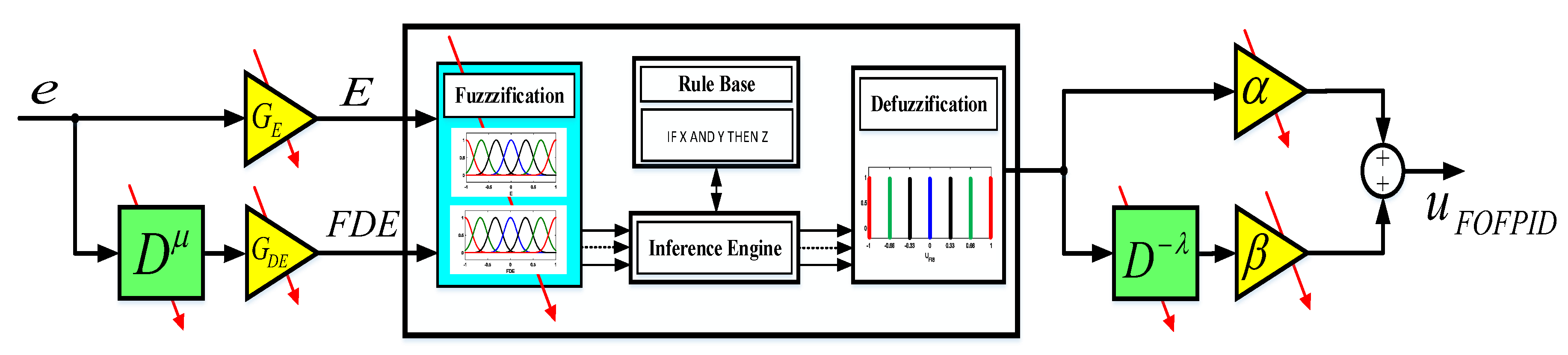
The structure of two inputs fractional order fuzzy PID controller with its tunable parameters is shown in Figure 4 where and are the input scaling factors while and are output scaling factors. is a fractional order differentiator with non-integer order while is a fractional order integrator with a non-integer order . Integer order fuzzy PID controller can be obtained easily from a fractional order fuzzy PID controller by setting the order of the differentiator and integrator in Figure 4 to an integer value, i.e., . However, the use of fractional order operators increases the degrees of freedom (DOF) of the fuzzy controller allowing it to generate output values that cannot be generated using an integer order fuzzy controller.
The input scaling factors perform a scaling or normalization of the inputs from the real values into a normalized universe of discourse [−1,1], while the output scaling factors , perform an inverse scaling or denormalization of the fuzzy controller output into applicable values suitable for the system. The performance of the fuzzy logic PID controller depends strongly on the values of these scaling factors [19]. Scaling factors has a global effect on the performance of the fuzzy controller. Therefore, these scaling factors must be properly tuned to achieve the desired system performance. Optimization algorithms represent an efficient tool for tuning the scaling factors of fuzzy controllers [19].
The inputs of the fractional order fuzzy PID controller are the error and the fractional derivative of error , which are scaled using the input scaling factors and respectively into and . The output is the control signal which is scaled using the output scaling factors and where:
where
where is the generating function for the Al-Alaoui operator and and are discrete transfer functions approximating the fractional-order differentiator and integrator respectively obtained using the Al-Alaoui operator. is a nonlinear function represent the fuzzy reasoning.
In this paper, seven membership functions (MFs) namely NB, NM, NS, Z, PS, PM and PB are used for the inputs and the output . Gaussian MFs are selected for the input variables. The Gaussian MF is defined by:
where is the mean of the membership function and is the standard deviation.
In this work, for computational efficiency, a zero-order Takagi-Sugeno-Kang (TSK) fuzzy inference is used, where the output of each rule is simply a constant or a singleton. The type and the parameters of the membership functions used affect the performance of the fuzzy controller. An optimization algorithm has been used for tuning the parameters of the membership functions [19,42]. The inputs and output membership functions for the fractional order fuzzy PID controller with its design parameters are shown in Figure 5.
The fuzzy rule used for the fractional order fuzzy PID controller has the following form:
where and are Gaussian fuzzy sets, while is a singleton. The complete rule base of the fractional order fuzzy PID controller with 49 rules is given in Table 2. This rule base has been selected according to [43].
4. Optimization Tool
4.1. Neural Network Algorithm (NNA)
Artificial Neural Networks (ANNs) map the input data to the target data through an iterative update of the weights of the ANNs to reduce the mean square error between the predicted output and the target output. The neural network algorithm (NNA) is based on the concepts and the structure of the ANNs to generate new solutions where the best searching agent in the population is considered as the target and the procedures of the algorithm tries to make all the searching agents follow that target solution [31].
NNA is a population-based algorithm where it starts with an initial population of randomly generated solutions within the search space. Each individual or searching agent in the population is called a “pattern solution”, each pattern solution is a vector of representing the input data of the NNA. .
To start the NNA optimization algorithm, a pattern solution matrix X with size is randomly generated between the lower and upper bounds of the search space. The population of pattern solution is given by:
where
where and are vectors representing the lower and upper bounds of the search space.
Like ANNs, in NNA each pattern solution will have its corresponding weight where . The weights array is given by:
where is a square matrix of uniformly distributed random numbers between 0 and 1. The weight of the pattern solution is involved in the generation of a new candidate solution.
In NNA, the initial weights are random numbers and its value is updated as the iteration number increases according to the calculated error of the network. The weight values are constrained such that the summation of the weights for any pattern solution should not exceed one, defined mathematically as follows:
These constraints for weight values are used to control the bias of movement and the generation of new pattern solutions. Without this constraint, the algorithm will be stuck in a local optimum solution [31].
The fitness of each pattern solution is computed by the evaluation of the objective function using the corresponding pattern solution .
where is the objective function.
After the fitness calculation for all pattern solutions, the pattern solution with the best fitness is considered as the target solution with a target position , target fitness and target weight . The NNA models an ANN with inputs each input of D dimension(s) and only one target output [31].
Inspired by the weight summation technique used in ANNs, the new pattern solution is generated as follows:
where k is an iteration index.
After the new pattern solutions are generated from the previous population, the weight matrix is updated as well using the following equation:
where the constraints (37) and (38) must be satisfied during the optimization process.
For better exploration of the search space, a bias operator is used in the NNA algorithm. The bias operator is used to modify a certain percentage of the pattern solutions generated in the new population as well as the updated weight matrix . The bias operator prevents the algorithm from premature convergence by modifying a certain number of individuals in the population to explore other places in the search space, which has not been visited by the population. For more details about the bias strategy, the reader can refer to reference [31].
A modification factor is used to determine the percentage of the pattern solutions to be modified using the bias operator. The initial value of is set to 1 meaning that all individuals in the population are biased. The value of will be adaptively reduced at each iteration using any possible reduction technique such as follows:
where is a positive number smaller than 1 originally selected as 0.99.
The reduction of the modification factor is made to enhance the exploitation of the algorithm as the iterations increase by allowing the algorithm to search for the optimum solution near to the target solution especially at the final iterations.
Unlike ANNs, in NNA the transfer function operator is used to generate better-quality solutions. The transfer function operator (TF) is defined by the following equation:
Using the transfer function operator, the updated pattern solution is transferred from its current position to a new updated position towards the target pattern solution .
In NNA, at early iterations the bias operator has more chances to generate a new pattern solution meaning that more possible opportunities for discovering unvisited pattern solutions as well as using new weight values. As the iteration number increases, the chance of applying the bias operator decreases while the transfer function (TF) operator will have more chance enhancing the exploitation of the NNA especially at the final iterations.
NNA is considered as a dynamic optimization model because the generation of a new updated solution does not depend only on the previous value of that solution but also depends on all the population described mathematically as follows:
where and are the next and current locations of the pattern solution respectively.
4.2. Formulation of FOFPID Controller Design as an Optimization Problem
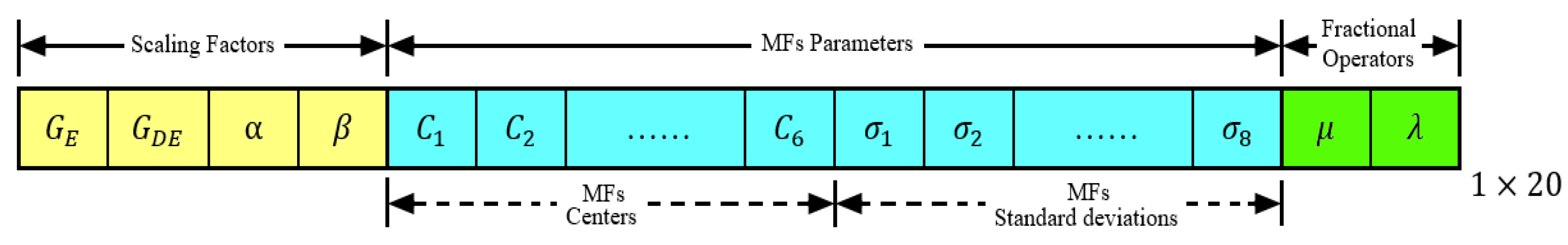
In this paper, the neural network algorithm (NNA) was used to optimize the fractional order fuzzy PID controller. NNA was used to obtain the optimal or suboptimal value of the four scaling factors , membership functions parameters for the two inputs and as well as the order of the fractional order operators . Each candidate pattern solution must contain these parameters of the FOFPID controllers as follows:
Gaussian membership functions are used for the inputs of the FOFPID controller. The Gaussian membership function is characterized by two parameters, which are the center and the standard deviation . In this paper, a technique for encoding the membership functions using the minimum number of parameters is used, where, the peer positive and negative membership functions have the same value of the mean , but with the opposite sign, and have the same standard deviation as shown in Figure 5. This approach of encoding reduces the total number of the membership functions’ parameters to be optimized to half, reducing the dimension of the optimization problem leading to a reduction of the computational cost. The total problem dimension is 20. The encoding of the controller parameters into a pattern solution is given in Figure 6.
The formulation of FOFPID controller design as an optimization problem is described as follows:
Minimize
Such that,
With the constrains:
where,
is the integral of the time weighted squared error, is the error signal and is the time.
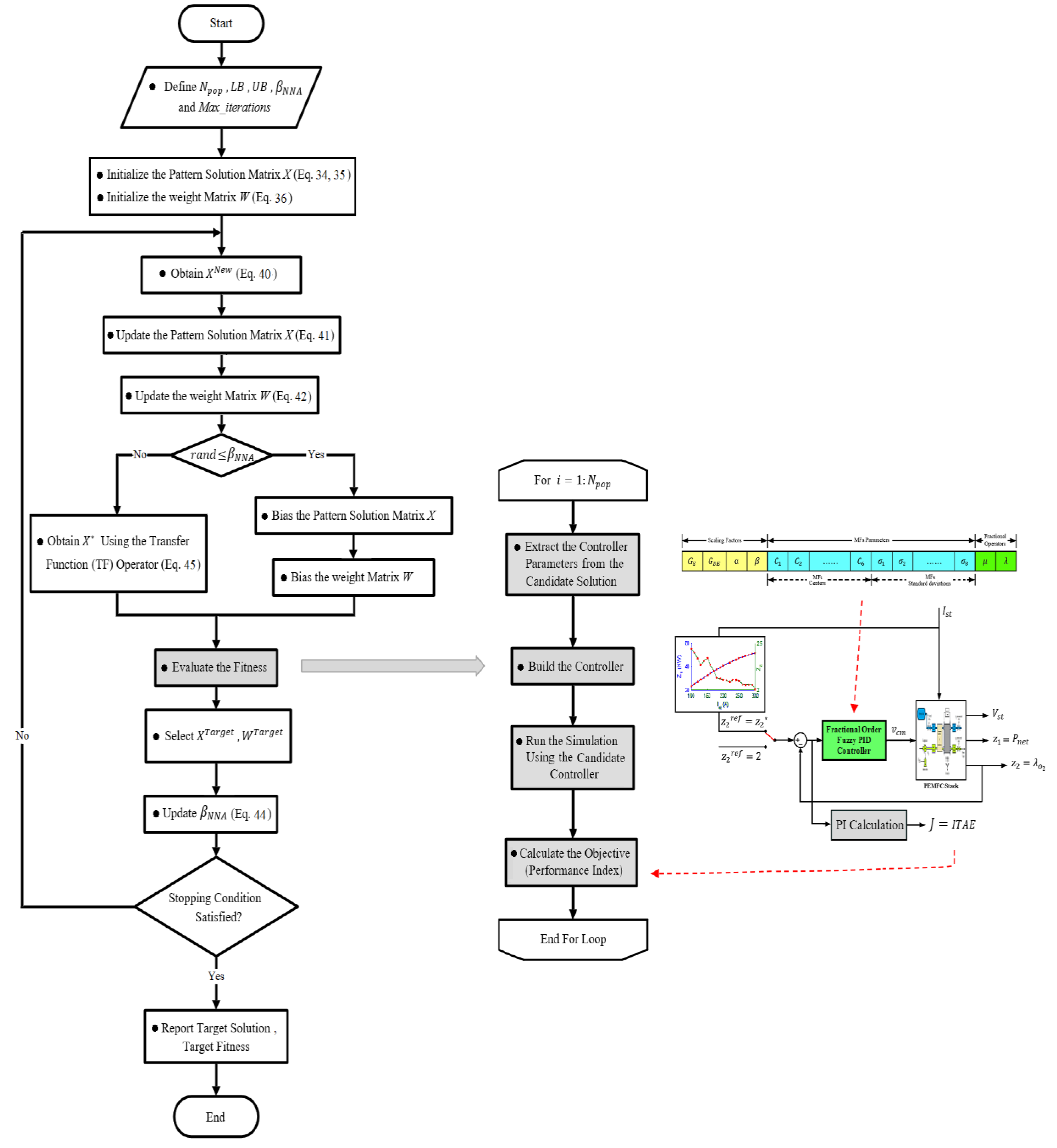
The detailed procedures for using NNA for the optimization of the FOFPID controller are described in Figure 7.
The optimized membership functions for both inputs of the FOFPID controller are shown in Figure 8. The optimal values for are: and . Using the Al-Alawi operator, the truncated 5th order discrete transfer functions approximating and with a sampling interval = 0.001 s are:
5. Simulation Results and Discussion
To verify the performance, the efficiency and the robustness of the proposed controller (NNA optimized fractional order fuzzy PID controller), detailed simulations using a MATLAB/SIMULINK environment were carried-out and analyzed. The performance verification was divided into three tasks. The first task was to test the controller for constant set point mode with . The second task was to test the controller for maximum power point operation mode with , where is a function of the stack current. The third task was to test the robustness of the proposed controller against parameter uncertainty in the PEMFC stack system using the sensitivity analyses. For the validation of the simulation results, this work uses the same numerical values of the model parameters as well as the same profile of the disturbance used in a recent paper (reference [16]). Moreover, the simulation results are compared and verified to that of reference [16].
5.1. The First Task (Tracking Constant )
In this task, the controller is tested by applying different values of the disturbance , which cover the whole range of the operation of the PEMFC stack while keeping the oxygen excess ratio at a constant set point value . The profile of the disturbance, i.e., the PEMFC stack current is shown in Figure 9.
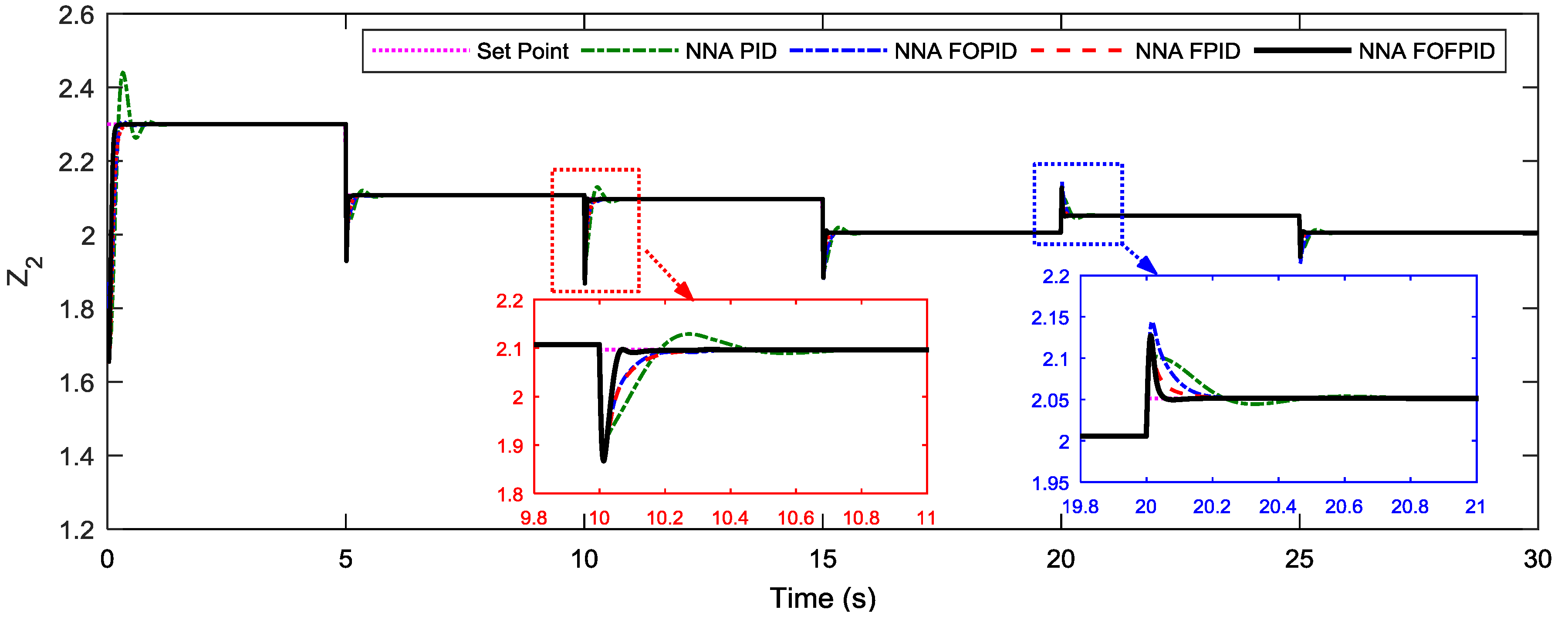
The PEMFC performance using four different controllers, which are the NNA optimized PID controller (NNA PID), NNA optimized fractional order PID controller (NNA FOPID), NNA optimized fuzzy PID controller (NNA FPID) and NNA optimized fractional order fuzzy PID controller (NNA FOFPID) is shown in Figure 10. Simulation results showed that a sudden increase in the stack current representing the disturbance to the system resulted in a sudden reduction of the oxygen excess ratio . The proposed controller (NNA FOFPID) recovered from the disturbance effect faster than other controllers achieving the least settling time, rise time and fluctuations around the set point. At time = 20 s, a sudden reduction in the stack current caused a sudden increase in the oxygen excess ratio . The proposed controller (NNA FOFPID) recovered from the disturbance effect faster than other controllers achieving the least settling time and fluctuations around the set point.
Simulation results showed that, the proposed NNA optimized fractional order fuzzy PID controller (NNA FOFPID) significantly improved the transient response of the PEMFC air feeding system by reducing the settling time and fluctuations around the set point compared to other controllers.
Simulation results showed that the NNA FOPID controller could outperform the NNA PID controller. However, it could not outperform the NNA FPID controller. Simulation results showed that the proposed NNA FOFPID could outperform all the other three types of controllers achieving a better performance.
The variation of the stack voltage and the net power output of the PEMFC stack using the four controllers is shown in Figure 11 and Figure 12, respectively. It could be noticed that a sudden increase in the PEMFC stack current resulted in a sudden reduction in the oxygen excess ratio reducing the stack voltage . Although, the reduction of the PEMFC stack current, at time = 20 s, resulted in an increase in the oxygen excess ratio increasing the stack voltage , the net power output of the stack was reduced because of the increased power consumption of the compressor motor. The compressor motor voltage using the proposed NNA optimized fractional order fuzzy PID (NNA FOFPID) controller is shown in Figure 13.
A performance comparison based on the time domain performance indices is given in Table 3. Results showed that, NNA optimized controllers could outperform the controllers presented in reference [16]. The proposed NNA optimized fractional order fuzzy PID controller (NNA FOFPID) was superior and achieved the best time domain performance indices.
5.2. The Second Task (MPPT)
In this task, the proposed NNA FOFPID controller was tested for the maximum power point operation for the PEMFC stack by tracking a time-varying set-value , where the set-value is a function of the stack current to obtain the maximum net power output from the PEMFC stack as described in Section 2. The same profile of the disturbance used in task 1 was used in the maximum power point tracking mode (MPPT) task.
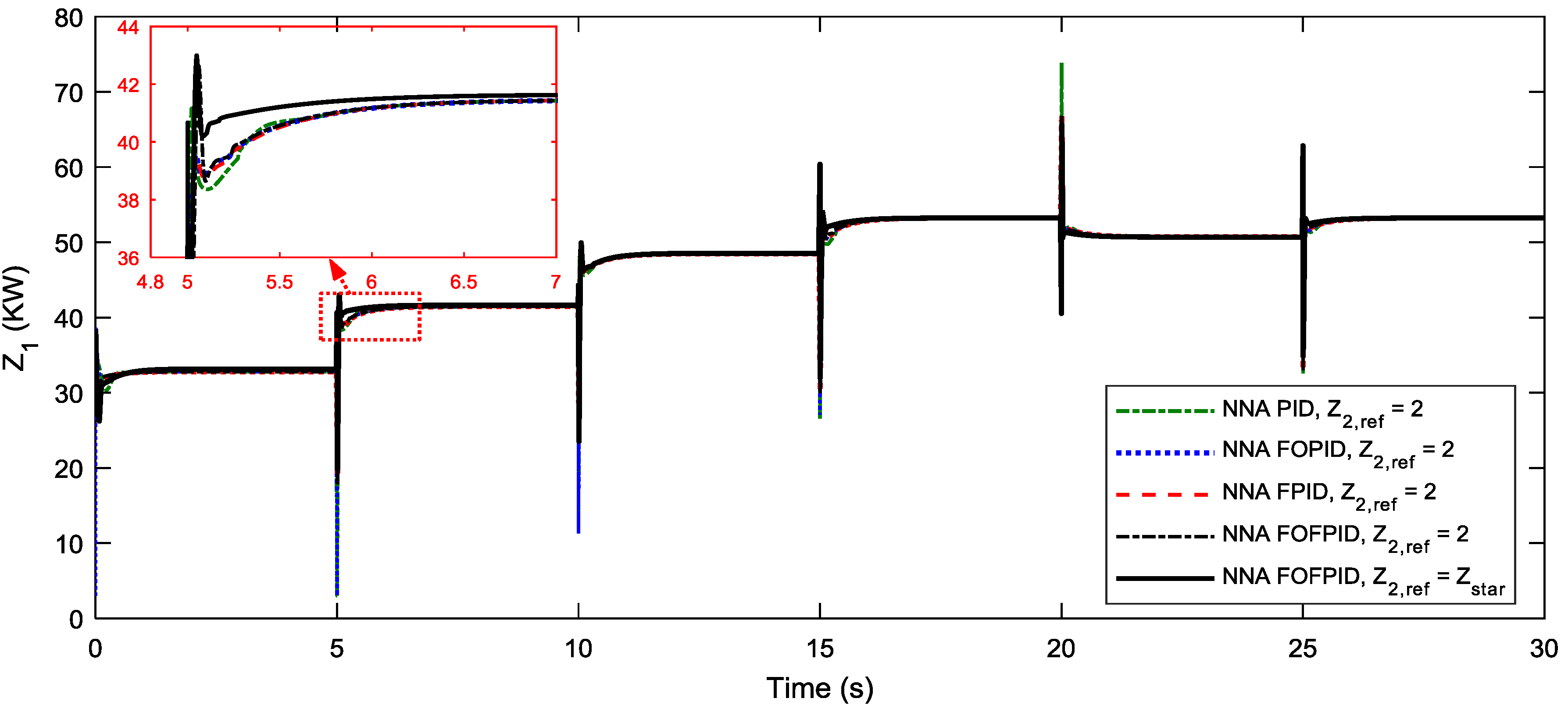
The PEMFC performance using the proposed controller and the other controllers for the maximum power point tracking mode (MPPT) is shown in Figure 14. Simulation results showed that the proposed NNA optimized fractional order fuzzy PID controller (NNA FOFPID) could outperform the other controllers achieving a better set point tracking with the least settling time and minimal fluctuations around the time-varying set value for both positive and negative set point changes achieving a better transient response. Results showed that the proposed NNA optimized fractional order PID controller (NNA FOPID) was better in both set point tracking and the disturbance rejection.
The variation of the stack voltage in the MPPT operation mode using the four controllers is shown in Figure 15. By comparing Figure 11 and Figure 15, it could be noticed that the stack voltage in the case of the MPPT operation mode was larger than that in case of the constant set point operation mode. The net power output of the PEMFC stack is shown in Figure 16. Simulation results showed that using a time-varying set-value , the net power output of the PEMFC stack was maximized. The compressor motor voltage in the MPPT operation mode using the NNA optimized fractional order fuzzy PID controller (NNA FOFPID) is shown in Figure 17.
A performance comparison based on the time domain performance indices for tracking a time-varying set-value is given in Table 4. The proposed NNA optimized fractional order fuzzy PID (NNA FOFPID) controller was superior and achieved the best time domain performance indices.
5.3. The Third Task (Sensitivity Analysis)
Sensitivity analyses were carried-out for testing the robustness of the proposed NNA optimized FOFPID controller against system parameters changes. The system parameters were varied independently by ±25% of their nominal values without changing the optimized parameter of the proposed NNA FOFPID controller. The time domain performance indices (ISE, IAE, ITSE and ITAE) for the nominal PEMFC air feeding system as well as the perturbed systems are shown in Table 5. The performance of the system with the different considered parameter uncertainty is shown in Figure 18.
The results of Table 5 and Figure 18 showed that applying ±25% uncertainties in , , , , and caused the time domain performance indices, overshoots, undershoots and settling time to deviate from their nominal values. However, these deviations were slight within an acceptable range and the system was dynamically stable. Sensitivity analyses showed that the PEMFC air feeding system with an NNA optimized FOFPID controller had satisfactory robustness against the considered parameter uncertainty range. It can be concluded that the NNA optimized FOFPID controller parameters obtained with the nominal system parameters can be used without retuning or resetting even the system parameters change in a considerable range.
6. Conclusions
In this paper, a fractional order fuzzy PID controller was proposed as an efficient controller for the PEMFC air feeding system. The proposed controller was optimized using the neural network algorithm (NNA). NNA was used to obtain the optimal value of the controller scaling factors and the order of the fractional differentiator and integrator as well as the optimal parameters of the input membership functions. Detailed simulation using a MATLAB/SIMULINK environment was carried-out to test the performance of the proposed NNA optimized FOFPID controller for different modes of operation of the PEMFC stack. Simulation results proved the efficiency and the superiority of the proposed NNA optimized FOFPID controller over other types of controllers. The proposed controller achieved a better set point tracking and disturbance rejection with minimal fluctuations around the set value with better transient response and minimum time domain performance indices. Sensitivity analyses were carried-out to test the robustness of the proposed controller against parameter uncertainty in the PEMFC air feeding system. Future research will concentrate on modifying the original NNA algorithm for improving its convergence with applications to PEMFC control using new control schemes.
Author Contributions
M.S.A. has proposed, conceptualization, simulations, analysis and written the manuscript. H.-J.Z. and Y.-X.S. validated the main idea and results, supervision and checked the whole manuscript. All authors organized and refined the manuscript in present form.
Funding
The APC was funded by Wuhan University of Technology.
Acknowledgments
M.S. AbouOmar acknowledges the Chinese Scholarship Council (CSC) and the Egyptian Government for the financial support. The authors would like to acknowledge the reviewers for their time and valuable comments regarding a high-quality paper.
Conflicts of Interest
The authors declare no conflict of interest.
Appendix A

Table A1.
System Parameters for Simulation b.
| Fuel Cells (FC) Data | |||
| Number of cells in fuel cell stack | 381 | ||
| The volume of the cathode | 0.01 | ||
| Throttle discharge coefficient for the cathode outlet | 0.0124 | ||
| Cathode outlet throttle area | 0.00175 | ||
| Supply manifold volume | 0.02 | ||
| Fuel cell temperature | 353.15 | ||
| Cathode inlet orifice constant | 0.3629 × | ||
| Air & Steam Properties | |||
| Ratio of specific heats of air | 1.4 | ||
| Nitrogen molar mass | 28 × | ||
| Oxygen molar mass | 32 × | ||
| Vapor molar mass | 18.02 × | ||
| Air molar mass | 28.97 × | ||
| Atmospheric temperature | 298.15 | ||
| Atmospheric pressure | 1.01325 × | ||
| Specific heat of air at constant pressure | 1004 | ||
| Average relative humidity of the ambient air | 0.5 | ||
| Oxygen mole fraction | 0.21 | ||
| Electrochemistry | |||
| Faraday constant | 96.487 | ||
| Universal gas constant | 8.31451 | ||
| Compressor (CP) | |||
| Compressor efficiency | 80% | ||
| Compressor inertia | 5 × | ||
| Compressor Motor (CM) | |||
| Compressor motor resistance | 0.82 | ||
| Motor constant | 0.0225 | ||
| Motor constant | 0.0153 | ||
| Motor mechanical efficiency | 98% | ||
b: Adopted with permission from reference [16] Copyright (2017) Elsevier.
References
- Pathapati, P.R.; Xue, X.; Tang, J. A new dynamic model for predicting transient phenomena in a PEM fuel cell system. Renew. Energy 2005, 30, 1–22. [Google Scholar] [CrossRef]
- Liu, J.; Gao, Y.; Su, X.; Wack, M.; Wu, L. Disturbance-observer-based control for air management of PEM fuel cell systems via sliding mode technique. IEEE Trans. Control Syst. Technol. 2018, 99, 1–10. [Google Scholar] [CrossRef]
- Vahidi, A.; Stefanopoulou, A.; Peng, H. Current management in a hybrid fuel cell power system: A model-predictive control approach. IEEE Trans. Control Syst. Technol. 2006, 14, 1047–1057. [Google Scholar] [CrossRef]
- Pukrushpan, J.T.; Peng, H.; Stefanopoulou, A.G. Control-Oriented Modeling and Analysis for Automotive Fuel Cell Systems. J. Dyn. Syst. Meas. Control 2004, 126, 14–25. [Google Scholar] [CrossRef]
- Pukrushpan, J.T.; Stefanopoulou, A.G.; Huei, P. Modeling and Control for PEM Fuel Cell Stack System. In Proceedings of the American Control Conference, Anchorage, AK, USA, 8–10 May 2002; Volume 4, pp. 3117–3122. [Google Scholar]
- Pukrushpan, J.T.; Stefanopoulou, A.G.; Huei, P. Control of fuel cell breathing. IEEE Control Syst. 2004, 24, 30–46. [Google Scholar]
- Grujicic, M.; Chittajallu, K.M.; Law, E.H.; Pukrushpan, J.T. Model-based control strategies in the dynamic interaction of air supply and fuel cell. Proc. Inst. Mech. Eng. Part A J. Power Energy 2004, 218, 487–499. [Google Scholar] [CrossRef]
- Niknezhadi, A.; Allué-Fantova, M.; Kunusch, C.; Ocampo-Martínez, C. Design and implementation of LQR/LQG strategies for oxygen stoichiometry control in PEM fuel cells based systems. J. Power Sour. 2011, 196, 4277–4282. [Google Scholar] [CrossRef] [Green Version]
- Talj, R.; Hilairet, M.; Ortega, R. Second order sliding mode control of the moto-compressor of a PEM fuel cell air feeding system, with experimental validation. In Proceedings of the 35th Annual Conference of IEEE Industrial Electronics, Porto, Portugal, 3–5 November 2009; pp. 2790–2795. [Google Scholar]
- Laghrouche, S.; Liu, J.; Ahmed, F.S.; Harmouche, M.; Wack, M. Adaptive second-order sliding mode observer-based fault reconstruction for PEM fuel cell air-feed system. IEEE Trans. Control Syst. Technol. 2015, 23, 1098–1109. [Google Scholar] [CrossRef]
- Han, J.; Yu, S.; Yi, S. Adaptive control for robust air flow management in an automotive fuel cell system. Appl. Energy 2017, 190, 73–83. [Google Scholar] [CrossRef]
- Gruber, J.K.; Doll, M.; Bordons, C. Design and experimental validation of a constrained MPC for the air feed of a fuel cell. Control Eng. Pract. 2009, 17, 874–885. [Google Scholar] [CrossRef]
- Wang, Y.-X.; Xuan, D.-J.; Kim, Y.-B. Design and experimental implementation of time delay control for air supply in a polymer electrolyte membrane fuel cell system. Int. J. Hydrogen Energy 2013, 38, 13381–13392. [Google Scholar] [CrossRef]
- Sanchez, V.M.; Barbosa, R.; Arriaga, L.G.; Ramirez, J.M. Real time control of air feed system in a PEM fuel cell by means of an adaptive neural-network. Int. J. Hydrogen Energy 2014, 39, 16750–16762. [Google Scholar] [CrossRef]
- Beirami, H.; Shabestari, A.Z.; Zerafat, M.M. Optimal PID plus fuzzy controller design for a PEM fuel cell air feed system using the self-adaptive differential evolution algorithm. Int. J. Hydrogen Energy 2015, 40, 9422–9434. [Google Scholar] [CrossRef]
- Baroud, Z.; Benmiloud, M.; Benalia, A.; Ocampo-Martinez, C. Novel hybrid fuzzy-PID control scheme for air supply in PEM fuel-cell-based systems. Int. J. Hydrogen Energy 2017, 42, 10435–10447. [Google Scholar] [CrossRef] [Green Version]
- Robles Algarín, C.; Taborda Giraldo, J.; Rodríguez Álvarez, O. Fuzzy logic based MPPT controller for a PV system. Energies 2017, 10, 2036. [Google Scholar] [CrossRef]
- Sahu, B.K.; Pati, S.; Mohanty, P.K.; Panda, S. Teaching–learning based optimization algorithm based fuzzy-PID controller for automatic generation control of multi-area power system. Appl. Soft Comput. 2015, 27, 240–249. [Google Scholar] [CrossRef]
- Omar, M.S.A.; Khedr, T.Y.; Zalam, B.A.A. Particle swarm optimization of fuzzy supervisory controller for nonlinear position control system. In Proceedings of the 8th International Conference on Computer Engineering & Systems (ICCES), Cairo, Egypt, 26–28 November 2013; pp. 138–145. [Google Scholar]
- Podlubny, I. Fractional-order systems and PIλDμ controller. IEEE Trans. Autom. Control 1999, 44, 208–214. [Google Scholar] [CrossRef]
- Alomoush, M.I. Load frequency control and automatic generation control using fractional-order controllers. Electr. Eng. 2010, 91, 357–368. [Google Scholar] [CrossRef]
- Debbarma, S.; Saikia, L.C.; Sinha, N. AGC of a multi-area thermal system under deregulated environment using a non-integer controller. Electr. Power Syst. Res. 2013, 95, 175–183. [Google Scholar] [CrossRef]
- Sondhi, S.; Hote, Y.V. Management, Fractional order PID controller for load frequency control. Energy Convers. 2014, 85, 343–353. [Google Scholar] [CrossRef]
- Taher, S.A.; Fini, M.H.; Aliabadi, S.F. Fractional order PID controller design for LFC in electric power systems using imperialist competitive algorithm. Ain Shams Eng. J. 2014, 5, 121–135. [Google Scholar] [CrossRef] [Green Version]
- Pan, I.; Das, S. Fractional-order load-frequency control of interconnected power systems using chaotic multi-objective optimization. Appl. Soft Comput. 2015, 29, 328–344. [Google Scholar] [CrossRef] [Green Version]
- Das, S.; Pan, I.; Das, S.; Gupta, A. A novel fractional order fuzzy PID controller and its optimal time domain tuning based on integral performance indices. Eng. Appl. Artif. Intell. 2012, 25, 430–442. [Google Scholar] [CrossRef] [Green Version]
- Pan, I.; Das, S. Fractional order fuzzy control of hybrid power system with renewable generation using chaotic PSO. ISA Trans. 2016, 62, 19–29. [Google Scholar] [CrossRef] [PubMed] [Green Version]
- Kumar, A.; Kumar, V. Communications, Hybridized ABC-GA optimized fractional order fuzzy pre-compensated FOPID control design for 2-DOF robot manipulator. AEU Int. J. Electron. 2017, 79, 219–233. [Google Scholar] [CrossRef]
- Mahto, T.; Mukherjee, V. Distribution, Fractional order fuzzy PID controller for wind energy-based hybrid power system using quasi-oppositional harmony search algorithm. IET Gener. Transm. 2017, 11, 3299–3309. [Google Scholar] [CrossRef]
- Arya, Y.; Kumar, N. BFOA-scaled fractional order fuzzy PID controller applied to AGC of multi-area multi-source electric power generating systems. Swarm Evol. Comput. 2017, 32, 202–218. [Google Scholar] [CrossRef]
- Sadollah, A.; Sayyaadi, H.; Yadav, A. A dynamic metaheuristic optimization model inspired by biological nervous systems: Neural network algorithm. Appl. Soft Comput. 2018, 71, 747–782. [Google Scholar] [CrossRef]
- Pukrushpan, J.T. Modeling and Control of Fuel Cell Systems and Fuel Processors; University of Michigan: Ann Arbor, MI, USA, 2003. [Google Scholar]
- Suh, K.W. Modeling, analysis and control of fuel cell hybrid power systems. Ph.D. Thesis, University of Michigan, Ann Arbor, MI, USA, January 2006. [Google Scholar]
- Deng, H.; Li, Q.; Cui, Y.; Zhu, Y.; Chen, W. Nonlinear controller design based on cascade adaptive sliding mode control for PEM fuel cell air supply systems. Int. J. Hydrogen Energy 2018. [Google Scholar] [CrossRef]
- Gruber, J.K.; Bordons, C.; Dorado, F. Nonlinear control of the air feed of a fuel cell. In Proceedings of the American Control Conference, Seattle, WA, USA, 11–13 June 2008; pp. 1121–1126. [Google Scholar]
- Talj, R.J.; Hissel, D.; Ortega, R.; Becherif, M.; Hilairet, M. Experimental Validation of a PEM Fuel-Cell Reduced-Order Model and a Moto-Compressor Higher Order Sliding-Mode Control. IEEE Trans. Ind. Electron. 2010, 57, 1906–1913. [Google Scholar] [CrossRef]
- Talj, R.; Ortega, R.; Hilairet, M. A controller tuning methodology for the air supply system of a PEM fuel-cell system with guaranteed stability properties. Int. J. Control 2009, 82, 1706–1719. [Google Scholar] [CrossRef]
- Liu, J.; Gao, Y.; Geng, S.; Wu, L. Nonlinear control of variable speed wind turbines via fuzzy techniques. IEEE Access 2017, 5, 27–34. [Google Scholar] [CrossRef]
- Chen, Y.; Vinagre, B.M.; Podlubny, I. Continued fraction expansion approaches to discretizing fractional order derivatives—An expository review. Nonlinear Dyn. 2004, 38, 155–170. [Google Scholar] [CrossRef]
- Chen, Y.Q.; Moore, K.L. Discretization schemes for fractional-order differentiators and integrators. IEEE Trans. Circuits Syst. Fundam. Theory Appl. 2002, 49, 363–367. [Google Scholar] [CrossRef] [Green Version]
- Petrás, I. Fractional derivatives, fractional integrals, and fractional differential equations in Matlab. In Engineering Education and Research Using MATLAB; InTech: London, UK, 2011. [Google Scholar]
- Cheng, Y.-S.; Liu, Y.-H.; Hesse, H.; Naumann, M.; Truong, C.; Jossen, A. A PSO-Optimized Fuzzy Logic Control-Based Charging Method for Individual Household Battery Storage Systems within a Community. Energies 2018, 11, 469. [Google Scholar] [CrossRef]
- Sharma, R.; Rana, K.; Kumar, V. Performance analysis of fractional order fuzzy PID controllers applied to a robotic manipulator. Expert Syst. Appl. 2014, 41, 4274–4289. [Google Scholar] [CrossRef]
Figure 1.
The main components of a PEMFC stack system.

Figure 2.
The performance curves for the PEMFC stack at different levels of disturbance. (a) Maximum power point () for different levels of disturbance (). (b) as a function of the disturbance ().
Figure 2.
The performance curves for the PEMFC stack at different levels of disturbance. (a) Maximum power point () for different levels of disturbance (). (b) as a function of the disturbance ().

Figure 3.
The proposed NNA optimized fractional order Fuzzy PID control scheme for the PEMFC stack.

Figure 4.
Fractional order fuzzy PID controller with tunable parameters.

Figure 5.
Input and output MFs for the fractional order fuzzy PID controller with its design parameters.
Figure 5.
Input and output MFs for the fractional order fuzzy PID controller with its design parameters.

Figure 6.
The encoding of FOFPID controller parameters into a pattern solution.

Figure 7.
The procedures of FOFPID controller optimization using the NNA algorithm.

Figure 8.
The optimized input MFs for the FOFPID controller.

Figure 9.
The disturbance ω (Ist).

Figure 10.
The response of using four NNA optimized controllers for task 1 ().

Figure 11.
The stack voltage variation using the four NNA optimized controllers for task 1 ().

Figure 12.
The net power output () using the four NNA optimized controllers for task 1 ().

Figure 13.
The compressor motor voltage (vcm) using the proposed controller for task 1 ().

Figure 14.
The response of using four NNA optimized controllers for task 2 (MPPT).

Figure 15.
The stack voltage variation using the four NNA optimized controllers for task 2 (MPPT).

Figure 16.
The net power output comparison for constant and maximum power point operation .

Figure 17.
The compressor motor voltage (vcm) using the proposed controller for task 2 (MPPT).

Figure 18.
Sensitivity analyses for the PEMFC air feeding system with the proposed NNA optimized FOFPID controller for 25% uncertainty in different PEMFC stack parameters. (a) Uncertainty in . (b) Uncertainty in . (c) Uncertainty in . (d) Uncertainty in . (e) Uncertainty in . (f) Uncertainty in .
Figure 18.
Sensitivity analyses for the PEMFC air feeding system with the proposed NNA optimized FOFPID controller for 25% uncertainty in different PEMFC stack parameters. (a) Uncertainty in . (b) Uncertainty in . (c) Uncertainty in . (d) Uncertainty in . (e) Uncertainty in . (f) Uncertainty in .

Table 1.
PEMFC model constants a.
| PEMFC Model Constants | |
|---|---|
a: Adopted with permission from Reference [16] Copyright (2017) Elsevier.
Table 2.
Fractional order fuzzy PID controller rule base [43].
Table 2.
Fractional order fuzzy PID controller rule base [43].
| NB | NM | NS | Z | PS | PM | PB | ||
|---|---|---|---|---|---|---|---|---|
| NB | NB | NB | NB | NB | NM | NS | Z | |
| NM | NB | NB | NB | NM | NS | Z | PS | |
| NS | NB | NB | NM | NS | Z | PS | PM | |
| Z | NB | NM | NS | Z | PS | PM | PB | |
| PS | NM | NS | Z | PS | PM | PB | PB | |
| PM | NS | Z | PS | PM | PB | PB | PB | |
| PB | Z | PS | PM | PB | PB | PB | PB | |
Table 3.
Performance indices using different controllers for task 1 ().
| Controller | ISE | IAE | ITSE | ITAE |
|---|---|---|---|---|
| PID [16] | 0.0627 | 0.2903 | NA | 2.2741 |
| FLC [16] | 0.5045 | 1.1047 | NA | 8.0201 |
| HFPID [16] | 0.0249 | 0.1005 | NA | 0.6781 |
| NNA PID | 0.03711 | 0.1995 | 0.1032 | 1.356 |
| NNA FOPID | 0.02652 | 0.1261 | 0.07036 | 0.8443 |
| NNA FPID | 0.014 | 0.09013 | 0.06015 | 0.6539 |
| NNA FOFPID (proposed) | 0.009186 | 0.05291 | 0.04193 | 0.3639 |
Table 4.
Performance indices using different controllers for task 2 (MPPT).
| Controller | ISE | IAE | ITSE | ITAE |
|---|---|---|---|---|
| HFPID [16] | NA | NA | NA | NA |
| NNA PID | 0.04931 | 0.1938 | 0.062 | 1.034 |
| NNA FOPID | 0.03104 | 0.1238 | 0.04675 | 0.7024 |
| NNA FPID | 0.03671 | 0.1127 | 0.03346 | 0.4368 |
| NNA FOFPID (proposed) | 0.02459 | 0.0701 | 0.02513 | 0.2619 |
Table 5.
Sensitivity analysis for the PEMFC air feeding system with the proposed NNA FOFPID.
| Parameter | % Change | ISE | IAE | ITSE | ITAE |
|---|---|---|---|---|---|
| Nominal | 0 | 0.02459 | 0.0701 | 0.02513 | 0.2619 |
| +25% | 0.0239 | 0.07184 | 0.03055 | 0.3069 | |
| −25% | 0.0263 | 0.07017 | 0.01969 | 0.2255 | |
| +25% | 0.0256 | 0.07463 | 0.03141 | 0.3158 | |
| −25% | 0.0239 | 0.06669 | 0.01997 | 0.225 | |
| +25% | 0.03594 | 0.08698 | 0.03287 | 0.3187 | |
| −25% | 0.01389 | 0.05485 | 0.01815 | 0.2263 | |
| +25% | 0.02459 | 0.0701 | 0.02513 | 0.2619 | |
| −25% | 0.02459 | 0.0701 | 0.02513 | 0.2619 | |
| +25% | 0.03929 | 0.1005 | 0.04467 | 0.519 | |
| −25% | 0.01774 | 0.05987 | 0.02576 | 0.2671 | |
| +25% | 0.0313 | 0.07813 | 0.02625 | 0.2707 | |
| −25% | 0.01966 | 0.06367 | 0.02441 | 0.2571 |
© 2019 by the authors. Licensee MDPI, Basel, Switzerland. This article is an open access article distributed under the terms and conditions of the Creative Commons Attribution (CC BY) license (http://creativecommons.org/licenses/by/4.0/).
Share and Cite
MDPI and ACS Style
AbouOmar, M.S.; Zhang, H.-J.; Su, Y.-X. Fractional Order Fuzzy PID Control of Automotive PEM Fuel Cell Air Feed System Using Neural Network Optimization Algorithm. Energies 2019, 12, 1435. https://doi.org/10.3390/en12081435
AMA Style
AbouOmar MS, Zhang H-J, Su Y-X. Fractional Order Fuzzy PID Control of Automotive PEM Fuel Cell Air Feed System Using Neural Network Optimization Algorithm. Energies. 2019; 12(8):1435. https://doi.org/10.3390/en12081435
Chicago/Turabian StyleAbouOmar, Mahmoud S., Hua-Jun Zhang, and Yi-Xin Su. 2019. "Fractional Order Fuzzy PID Control of Automotive PEM Fuel Cell Air Feed System Using Neural Network Optimization Algorithm" Energies 12, no. 8: 1435. https://doi.org/10.3390/en12081435
Note that from the first issue of 2016, this journal uses article numbers instead of page numbers. See further details here.