Design of Gerotor Oil Pump with 2-Expanded Cardioids Lobe Shape for Noise Reduction

1
Department of Mechanical Convergence Technology, Pusan National University, Busan 46241, Korea
2
Research Institute of Mechanical Technology, Pusan National University, Busan 46241, Korea
3
School of Mechanical Engineering, Pusan National University, Busan 46241, Korea
*
Author to whom correspondence should be addressed.
Energies 2019, 12(6), 1126; https://doi.org/10.3390/en12061126
Submission received: 26 February 2019
/
Revised: 12 March 2019
/
Accepted: 19 March 2019
/
Published: 22 March 2019
(This article belongs to the Section F: Electrical Engineering)
Abstract
:Gerotor pump technology is being increasingly employed in innovative application fields, such as engines and as the hydraulic source of automatic transmissions. The most important issues in the automobile industry in recent years are improvement of fuel efficiency and noise reduction, so the existing studies relating to design of the gerotor profiles and the port in gerotor oil pumps have been conducted to ensure high flow rates and low irregularity. This study proposes a new gerotor lobe shape with 2-expanded cardioids to reduce the noise of the oil pump used in the automatic transmissions of automobiles. Theoretical equations to generate the tooth profile with 2-expanded cardioids was established, and then the gerotor profile to reduce noise was proposed using an automatic program. A design method for generation of a port shape suitable for the proposed gerotor was introduced, and performance tests (2000 rpm~3000 rpm) of the new oil pump with the suggested gerotor and port shape were implemented. The test results showed that the flow rate was improved by 7.3%~1.5% and the noise was reduced by 2.8 dB~4.8dB compared to those of the existing oil pump, so it was demonstrated that the design methods for the gerotor with 2-expanded cardioids and the port shape were validated. It is expected that the new lobe shape with 2-expanded cardioids and the port shape design method could be adopted in various fields, and will contribute to improving the performance of oil pumps.
1. Introduction
Gerotor pump technology is being increasingly employed in innovative application fields, such as engines and as the hydraulic source of automatic transmissions. This remarkable growth is based on its three main advantages: simplicity, versatility and performance [1]. The most important issues in the automobile industry in recent years are improvement of fuel efficiency and noise reduction, so studies relating to design of gerotor profiles and the ports of gerotor oil pumps have been conducted to achieve high flow rates and low irregularity.
Previous studies on gerotor lobe shape design mostly focused only on the trochoid curves (cycloid, epitrochoid and hypotrochoid), which have been used in a broad array of applications [2,3,4,5]. Mimmi presented a method for avoiding undercutting of cycloid pumps and determined the analytical expression of the limit curve [2]. Gamez presented a new design methodology of a trochoidal gear, which allows one to find the best gear set for the initial required design parameters, considering contact stress and volumetric characteristics [3]. Ravari implemented the optimization of an epitrochoidal gerotor according to volumetric, dynamic and geometric properties, and the results showed wear rates proportional to factor and the irregularity were significantly improved [4]. Bonandrini studied an epitrochoidal profile for internal rotary pumps to have superior flow-rate performance, and a tooth contact analysis was performed to consider possible transmission errors [5]. Om et al. presented a method to design the cross section of PCPs or DHMs with hypotrochoidal multilobes by using the differential geometric approach and established the formulae for the envelope and its offset curve and calculated the area efficiency of the cross section and curvature of the hypotrochoid [6], but they did not conduct a design of a new type of gerotor profile to improve the performance of oil pumps, considering design parameters relating to lobe shape. The authors have developed various lobe shapes by combining two or three geometric curves (2-ellipses, 3-ellipses, ellipse1-involute-ellipse2 and ellipse1-elliptical involute-ellipse2) to replace the existing gerotor with a single cycloid lobe shape, called parachoid, which has been adopted in the six-speed automatic transmission of an actual automobile [7,8,9]. Based on the authors’ previous studies, it was found that the performance of the gerotor with the two curves-combined lobe shape (2-ellipses) was better than that with the single lobe shapes (circle and ellipse) and the three curves-combined lobe shapes (3-ellipses, ellipse1-involute-ellipse2, and ellipse1-elliptical involute-ellipse 2), and the noise of the oil pump was reduced as the curvature radius of lobe shape increased.
Port shape is determined by gerotor profile, so if an unsuitable port shape is adopted in the oil pump, a fairly accurate performance cannot be guaranteed. The previous studies have only focused on fluid analysis to understand the flow characteristics of the oil pump by assembling the gerotor with the port. Ding reviewed a cavitation inception prediction method for an axial flow model pump, and fair agreement between experiment and simulation outcomes was found [10]. Frosina presented a tridimensional CFD analysis of the oil pump of a motorbike engine according to the temperature of the oil, velocity of the inner rotor and outlet pressure. The pump model results were compared with experimental data showing a good correlation between experimental and simulated data [11]. Kumar executed a CFD integrated development process for the gerotor pump using a 3D transient model [12]. Hsieh proposed a fluid analysis model based on a relief groove design to diminish collisions in gerotors [13], but previous works show deficiencies when establishing a design method for port shapes.
In this study, a new gerotor lobe shape with 2-expanded cardioids was proposed to reduce the noise of the oil pump used in the automatic transmission of an automobile. Theoretical equations to generate a tooth profile with 2-expanded cardioids was established, and the lobe shape was proposed through the automatic program, which was developed to obtain tooth profiles and to calculate performance parameters corresponding to the various input design parameters. In addition, the design method of a port suitable for the suggested gerotor was introduced, and noise reduction effects of the proposed gerotor and the port on the performances of the oil pump were validated through experimental tests.
2. Design of Gerotor with 2-Expanded Cardioids Lobe Shape
2.1. Suggestion of New Outer Lobe Shape (2-Expanded Cardioids) to Reduce Gerotor Noise
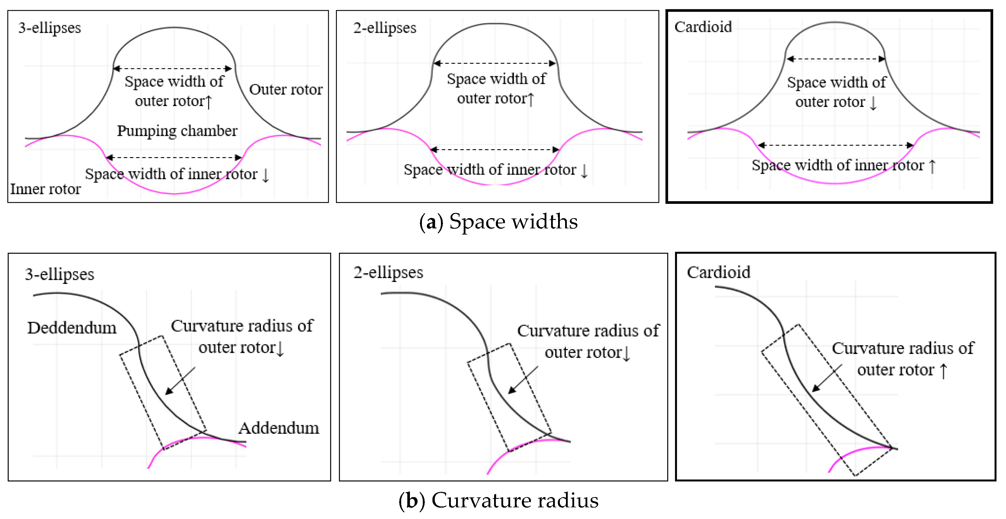
According to the authors’ previous studies based on the accumulated experiences in relation to lobe shape designs [7,8,9], it was found that the space width and curvature radius of the tooth profile, generated from deddendum to addendum, greatly influence the irregularity and contact stress, which are the main performance parameters relating to gerotor noise. In order to suggest a new outer lobe shape which is favorable to noise reduction, the effects of the tooth profile on irregularity and contact stress were analyzed by comparing the existing lobe shapes (3-ellipses, 2-ellipses and cardioid).
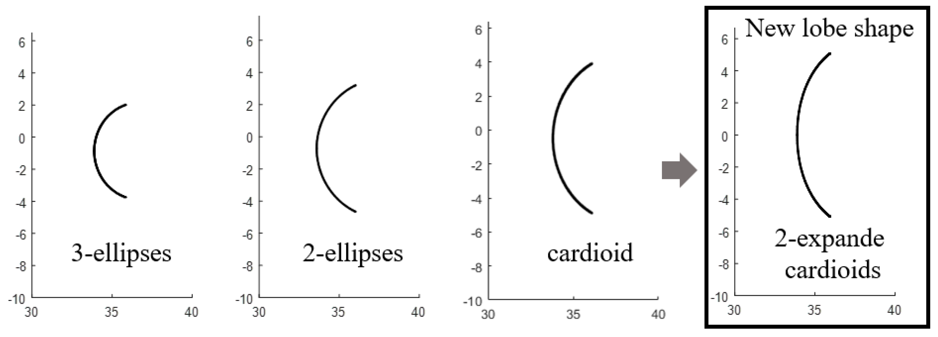
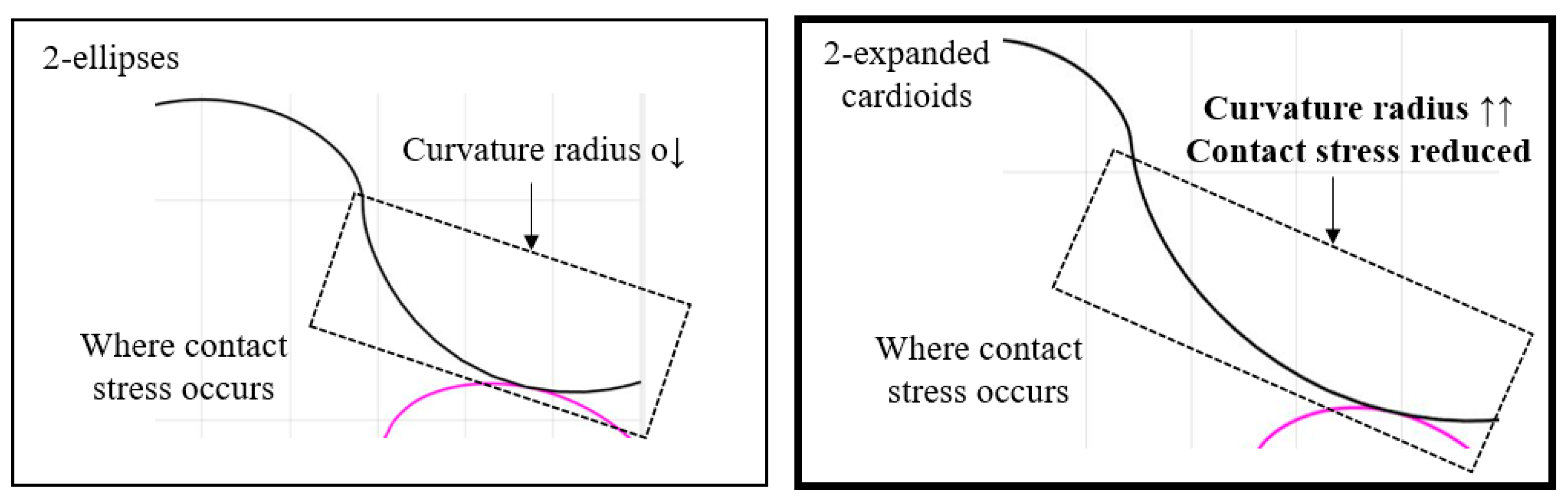
A cardioid lobe shape has a narrow space width with respect to the outer rotor and a wide space width with respect to the inner rotor, when compared to 3-ellipses and 2-ellipses lobe shapes, as shown in Figure 1a. Also, its curvature radius increases and changes more gradually as shown in Figure 1b, so this causes a reduction of irregularity and contact stress as shown in Table 1. Based on the abovementioned tendency to increase space width and curvature radius, the new lobe shape (2-expanded cardioid) shown in Figure 2 is suggested by rotating the expanded cardioid, which is generated by increasing the constants in the cardioid equation, and by combining two expanded cardioids, which are symmetric with respect to the x-axis.
2.2. Design of Outer Lobe Shape with 2-Expanded Cardioids
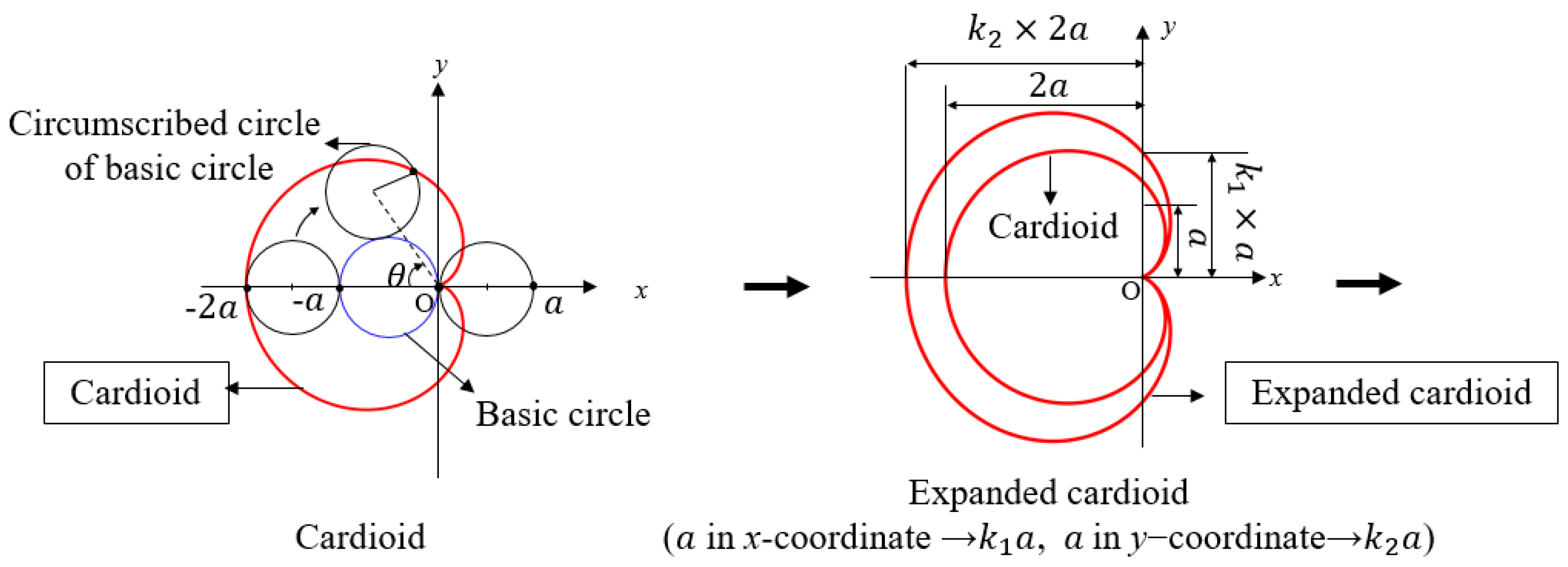
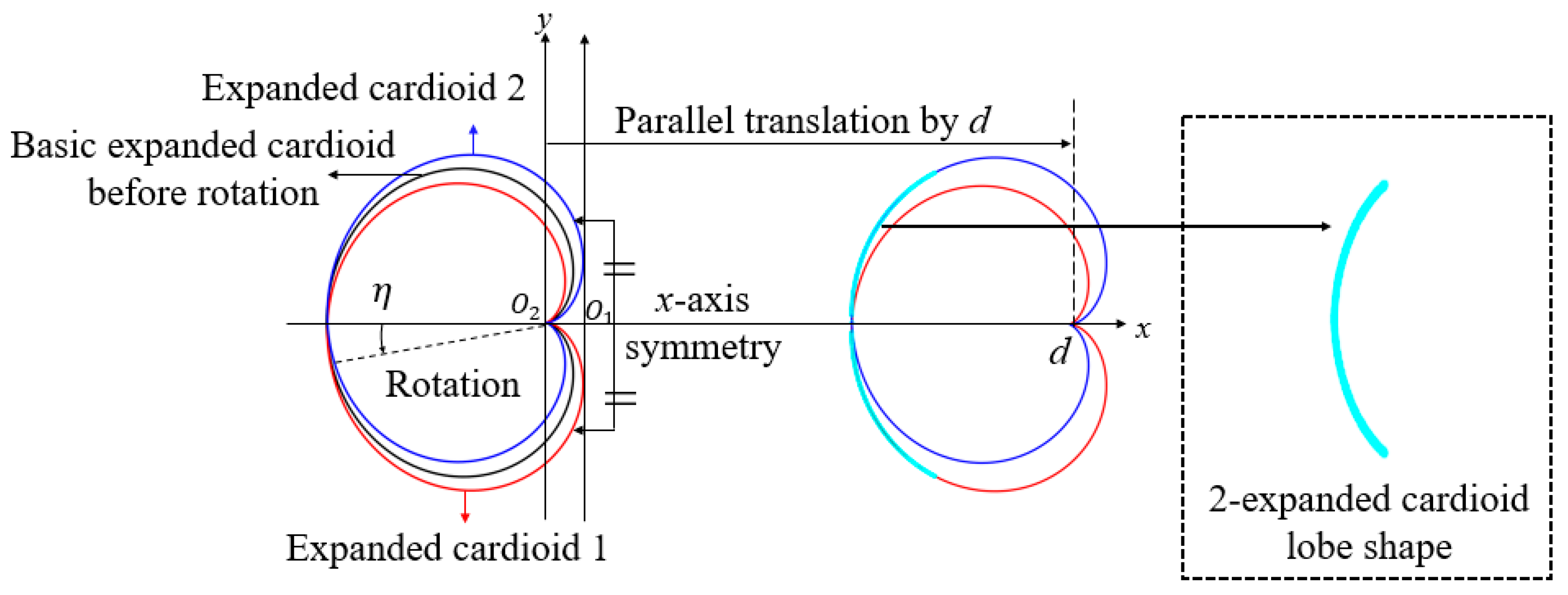
A cardioid is a plane curve traced by a point on the perimeter of a circle rolling (a circumscribed circle) around a fixed circle (basic circle) of the same diameter (a), and is expressed using Equations (1)–(2). The expanded cardioid given in Equations (3)–(4) is obtained by multiplying the constant (a) in the x and y coordinates of the cardioid equation by ‘k1’ and ‘k2’, respectively, as shown in Figure 3. The new lobe shape is composed of the expanded cardioid 1 (Equations (5)–(6)) and expanded cardioid 2 (Equations (7)–(8)). In order to derive the shape of expanded cardioid 1, the expanded cardioid rotates ‘η’ degrees in a counter-clockwise direction on its own center. By combining expanded cardioid 1 and 2, which are symmetric with respect to the x-axis, and moving ‘d’ in the x-direction as shown in Figure 4, the 2-expanded cardioids lobe shape is obtained from Equations (9)-(12), where O1 and O2 are the centers of the inner and outer rotors, and ‘d’ is the distance between the center of the outer rotor and the center of the 2-expanded cardioids lobe shape.
2.3. Constitutive Equations for the Contact Point of a 2-Expanded Cardioids Lobe Shape
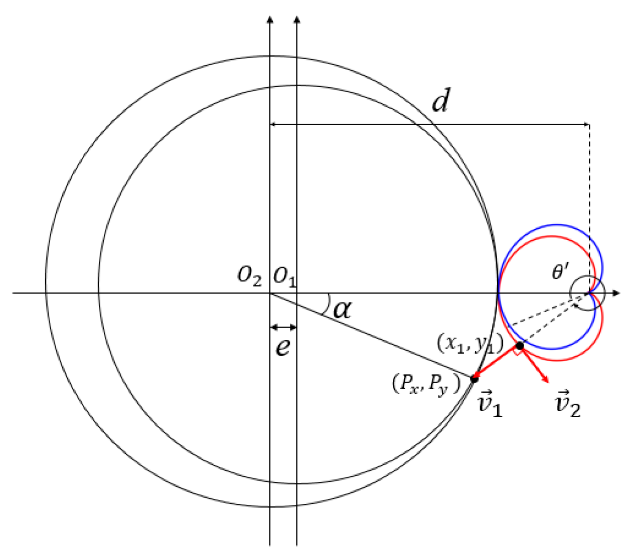
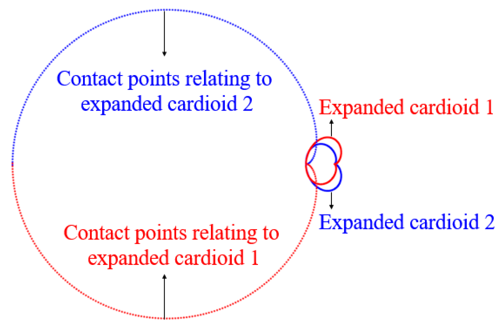
The Camus theory states that the direction vector () from a point on a lobe shape to the pitch point should be perpendicular to the vector () at the point on the expanded cardioid. A circular lobe shape is satisfied with the Camus theory, but in the case of a 2-expanded cardioids lobe shape, the normal line at a contact point is not directed toward the center of the outer lobe. Therefore, ‘θ’’, which enables the direction vector () from a point (x1, y1) on a lobe shape to the pitch point (Px, Py) to be orthogonal to the tangent vector () at the point, as shown in Figure 5, is calculated by the Newton-Raphson method within the range of error, 10−6 using Equations (13)–(15) [14]. The approximate contact points relating to the expanded cardioid 1 (C1) and expanded cardioid 2 (C2) obtained from Equations (16)–(18) are shown in Figure 6.
2.4. Generation of a Gerotor with 2-Exlanded Cardioids Lobe Shape
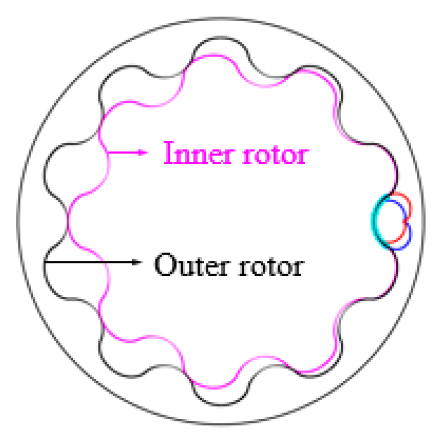
The profile of the inner rotor is generated by rotating ‘α’‘ clockwise from the contact point, (C1, C2) on the center (O1) of the inner rotor, and that of outer rotor is generated by rotating α clockwise from the contact point on the center of outer rotor (O2) as shown in Figure 7, where ‘r1’ and ‘r2’ are the radii of the pitch circles of the inner and outer rotors, respectively, and ‘e’ is the amount of eccentricity [14]:
2.5. Performances of Gerotor
Flow rate (Q), which is the amount of working oil in the chambers is calculated by using Equation (22), where Amax and Amin are the largest and smallest values of the maximum chamber areas, and ‘b’, ‘ρfluid’ and ‘ω1‘’ are the thickness of the gerotor, density of the working oil and rotational velocity of the inner rotor, respectively [15]. Irregularity (i) is proportional to the difference between the amount of fluid in the maximum chamber area (qmax) and that in minimum chamber area (qmin). as given by in Equation (23):
Specific sliding is the ratio of the sliding speed in a transverse plane of a contact point between mating gear teeth. It is the difference between the two rolling velocities that are tangential to the tooth profiles and perpendicular to the line of action. Formulas to calculate specific sliding values of inner and outer rotors (ss1 and ss2) are expressed in Equation (24), where ‘v1’ and ‘v2’ are the sliding speeds of the inner and outer rotors, respectively:
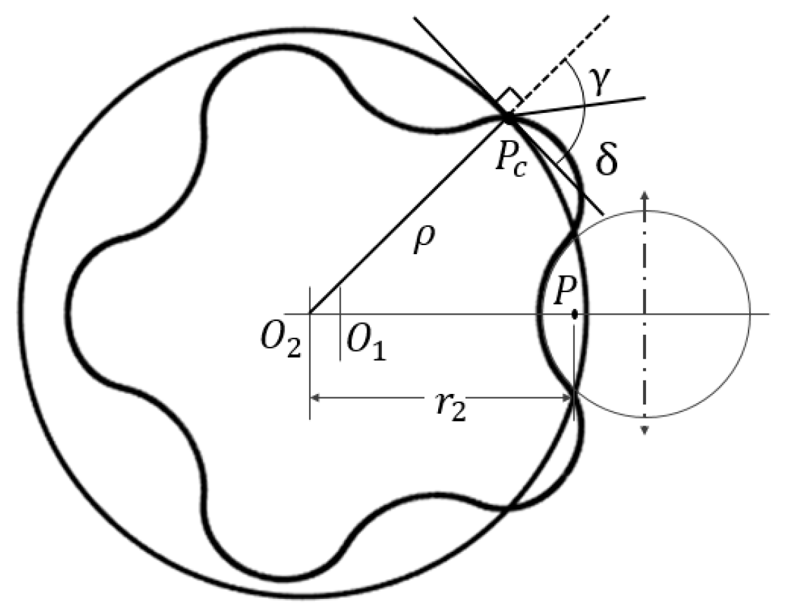
Pressure angle (δ) is the angle between the common normal to the contacting teeth and the common tangent to the pitch circles of meshing gears as illustrated in Figure 8, and calculated by using Equations (25)–(27):
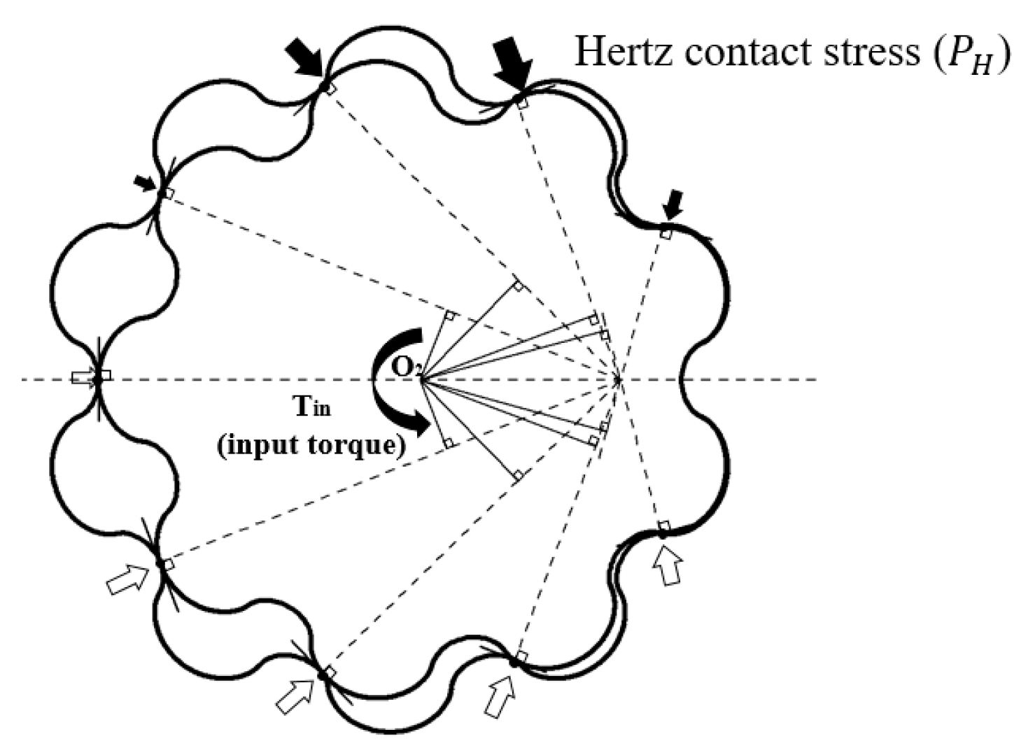
Contact stresses (PH) of two objects moving relatively shown in Figure 9 are generally calculated using the Hertzian theory expressed by Equation (28):
When the inner rotor contacts with outer rotor, they exert the same magnitude of contact force in the opposite direction to each other, so contact stresses occur inside the gerotor [16]. ‘F’ is the contact force to the inner rotor at a contact point; ‘E’ is elastic modulus of; ‘b’ is the thickness of gerotor; ‘R’ is the composite radius of curvature; ‘ρi’ and ‘ρo’ are the radii of curvatures of the inner and outer rotors, respectively.
2.6. Design of Gerotor with 2-Expanded Cardioids Lobe Shape Using Automatic Program
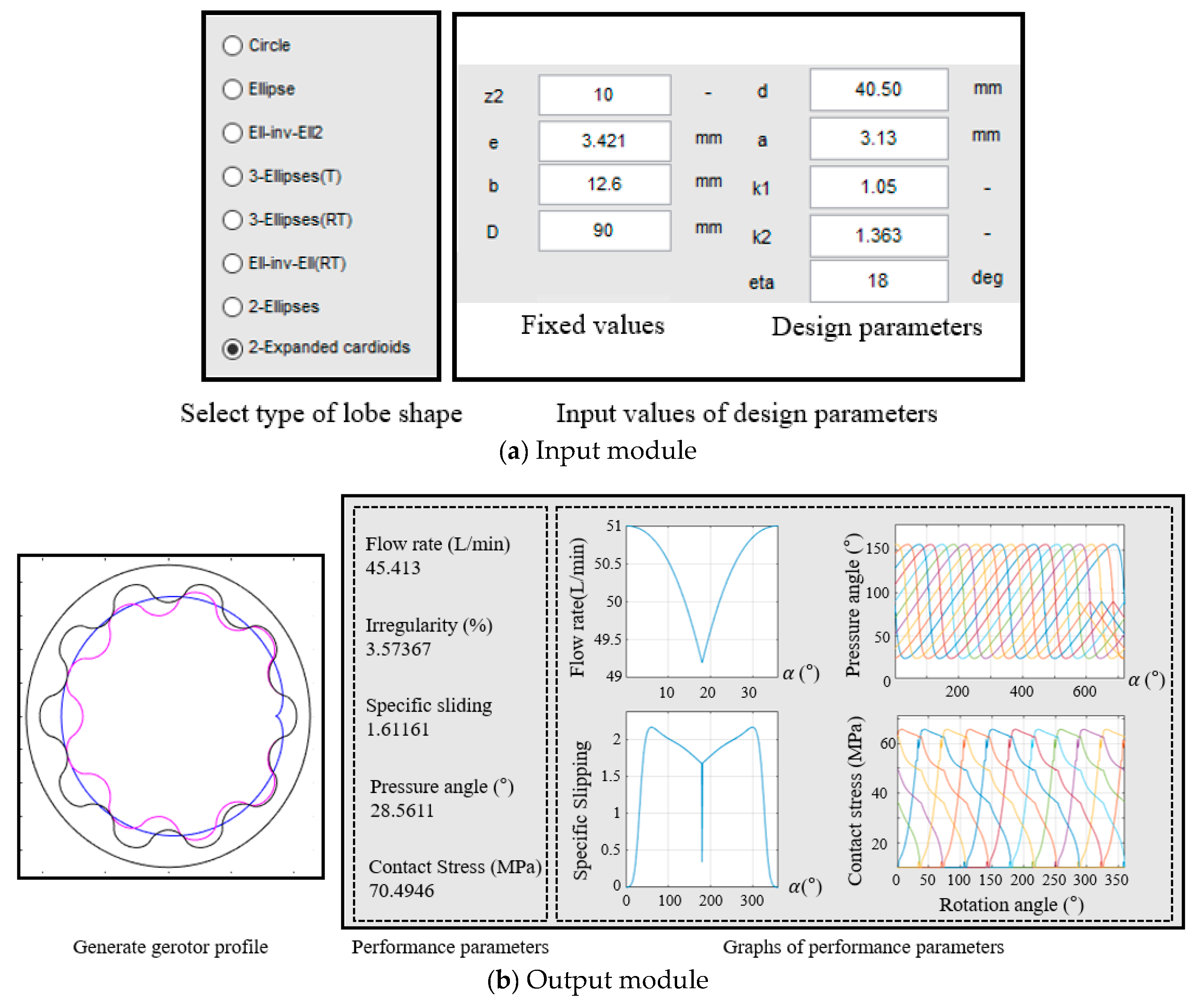
An automatic program to conduct gerotor design was developed using the commercial software MATLAB (R2018a, The MathWorks, Inc. Natick, MA, USA). The GUI is composed of an input module for entering the design parameters (‘d’, ‘a’, ‘k1’, ‘k2 ‘ and ‘η’) and an output module for displaying gerotor profile and performance parameters as shown Figure 10. In the input module shown in Figure 10a, if a type of lobe shape is chosen, design parameter-input-window corresponding to the lobe shape is activated. After entering values of the design parameters, gerotor profile and performance parameters are computed automatically in the output module as shown in Figure 10b. The fixed values, which are determined from the geometric constraints of gerotor used for the six-speed auto transmission, are as follows: the number of outer rotor tooth (z2), 10; eccentricity (e), 3.421 mm; thickness of gerotor (b), 12.6 mm; diameter of outer rotor (D), 90 mm.
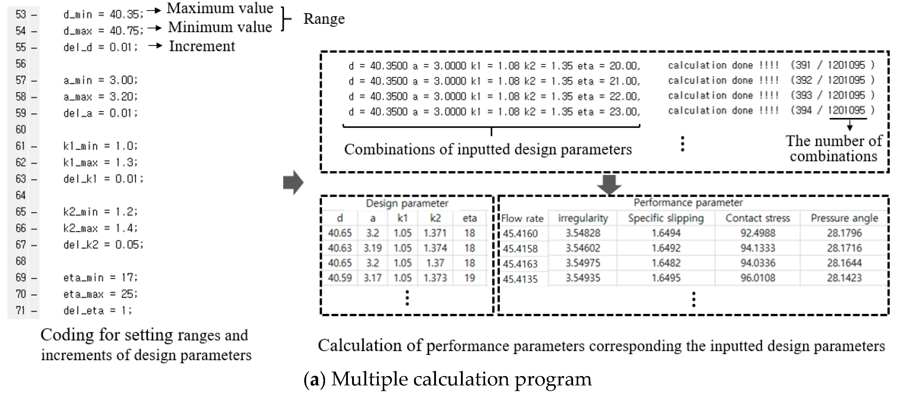
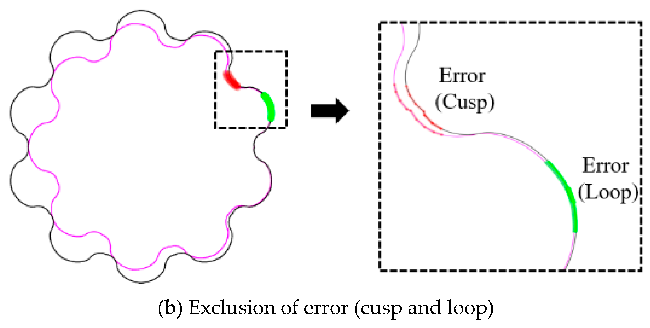
In the multiple calculation program, the ranges and increments of the design parameters are entered as shown Figure 11a, and then about 1.2 million of different gerotors and their performances corresponding to combinations of the input design parameters are created. Tooth profiles, which are not satisfying the kinematics constraints, such as a cusp or loop, are automatically excluded as shown in Figure 11b.
One of the characters of gerotor performance is that an increase of flow rate causes high irregularity, which conflict with each other, so the automobile industry demands a compromise for noise reduction while maintaining the flow rate of the existing gerotors. Oil pump noise is caused by two reasons: fluid dynamic noise is related to turbulence and whirl flow, and the main source is a pressure pulsation due to a sharp increase in irregularity; impact noise is mainly greatly attributable to the contact force between the two rotors [17,18]. A lower pressure angle reduces the impact force on the tooth, but decreases transmission errors due to weak mesh stiffness, and specific sliding largely influences slip power loss and tooth wear [19]. Hence, this study suggested a gerotor to reduce noise focusing on irregularity and contact stress, while providing a similar flow rate level (45.37L/min) as the previous gerotor with 2-ellipses lobe shape [7], which was the best model among the various gerotors developed in our laboratory. The comparison results between the performances of the proposed gerotor and those of the existing one show that the irregularity and contact stress are decreased by 4.54% and 37.9%, respectively, as shown in Table 2.
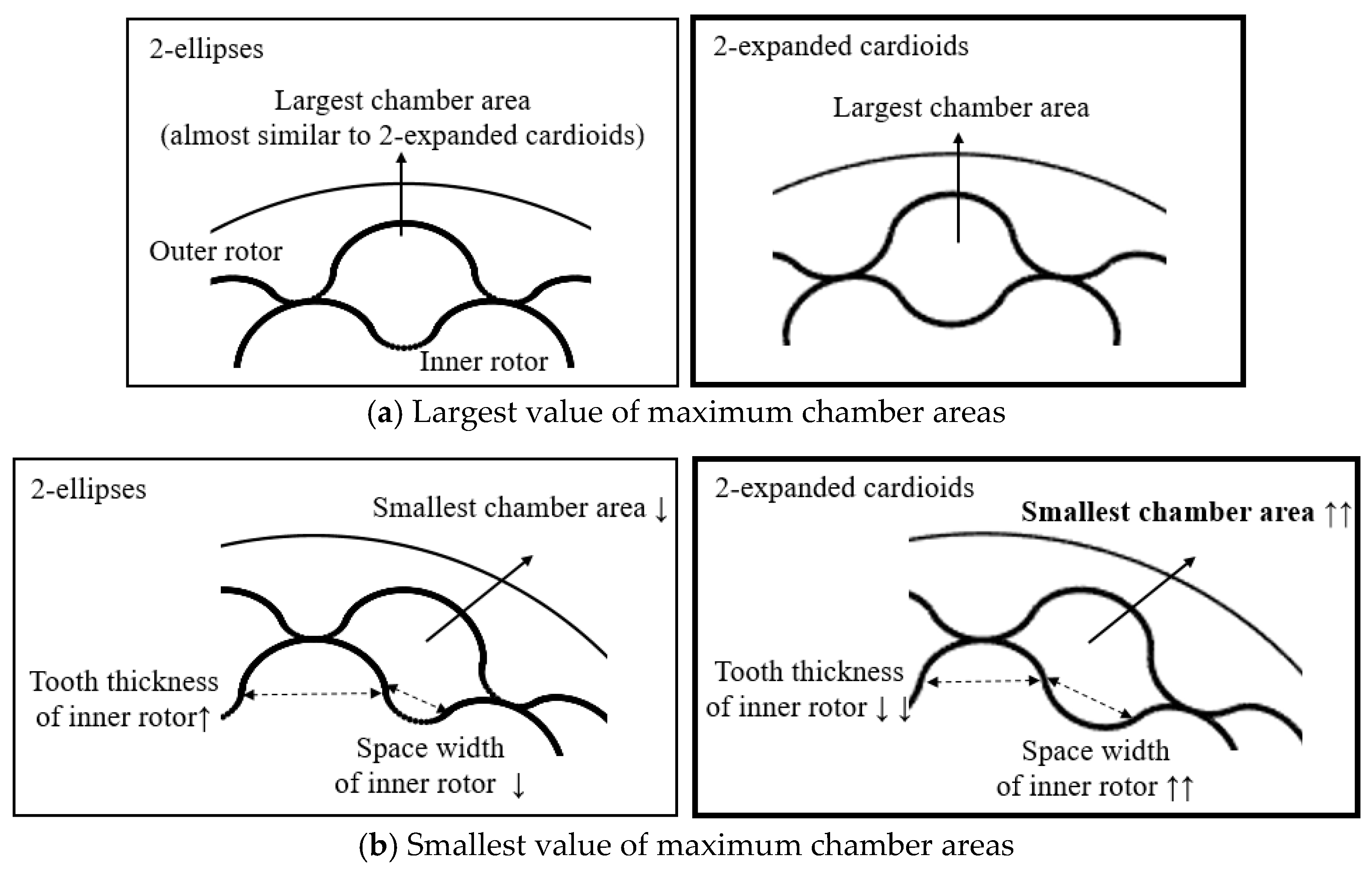
In order to verify the effects of the proposed gerotor on noise reduction, the relationship between the tooth profile features (space width, tooth thickness and curvature radius) and performance parameters (irregularity and contact stress) was analyzed. The largest maximum chamber area value of the four gerotors shown in Figure 12a are almost similar, whereas the smallest value of maximum chamber area of the proposed gerotor increased due to the large space width and narrow tooth thickness of the inner rotor as shown in Figure 12b. This implies that a small difference between the largest and the smallest flow rates at the maximum chamber causes a reduction of irregularity as shown in Table 3.
3. Design of Port for the Proposed Gerotor with 2-Expanded Cardioids Lobe Shape
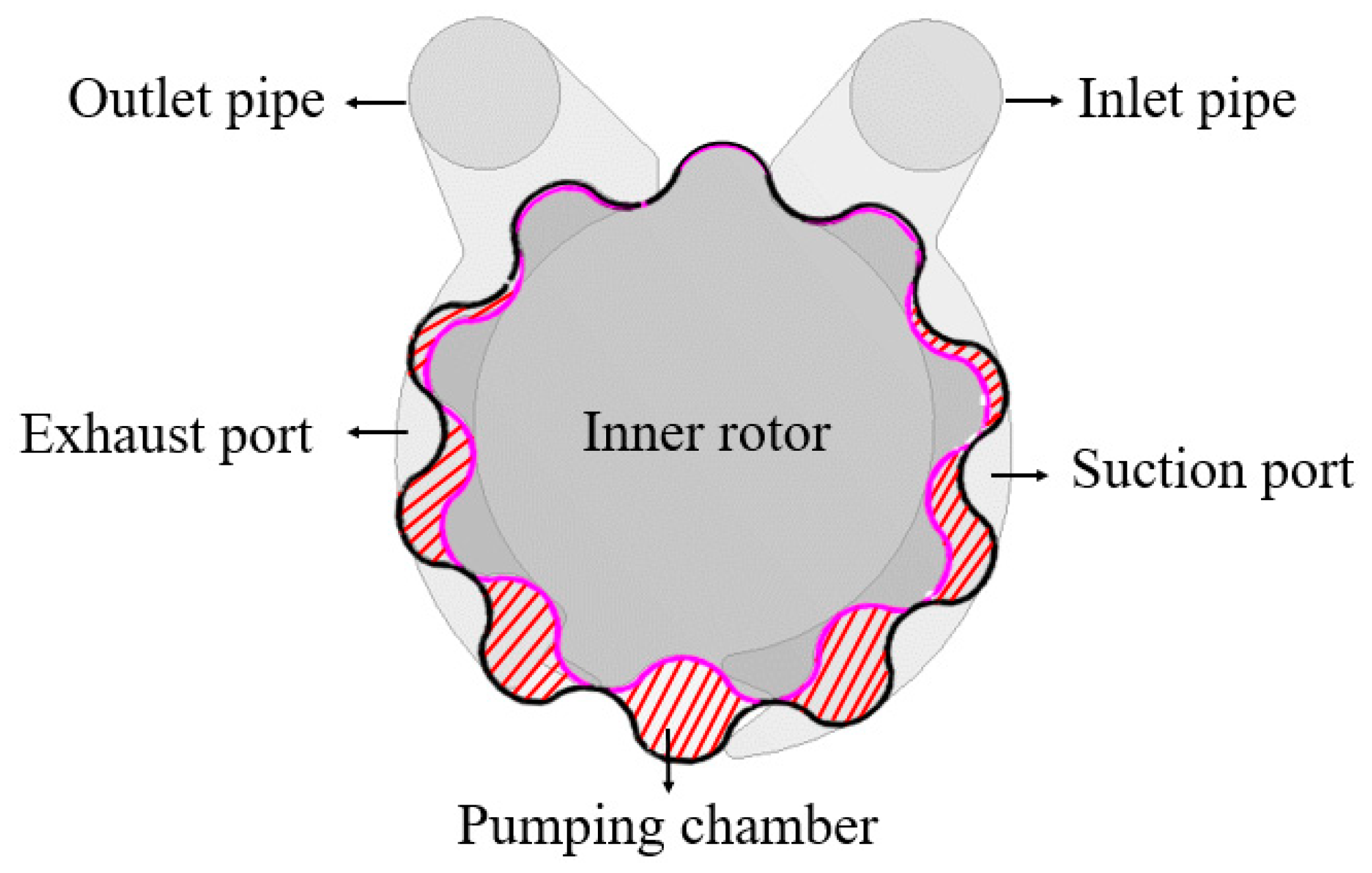
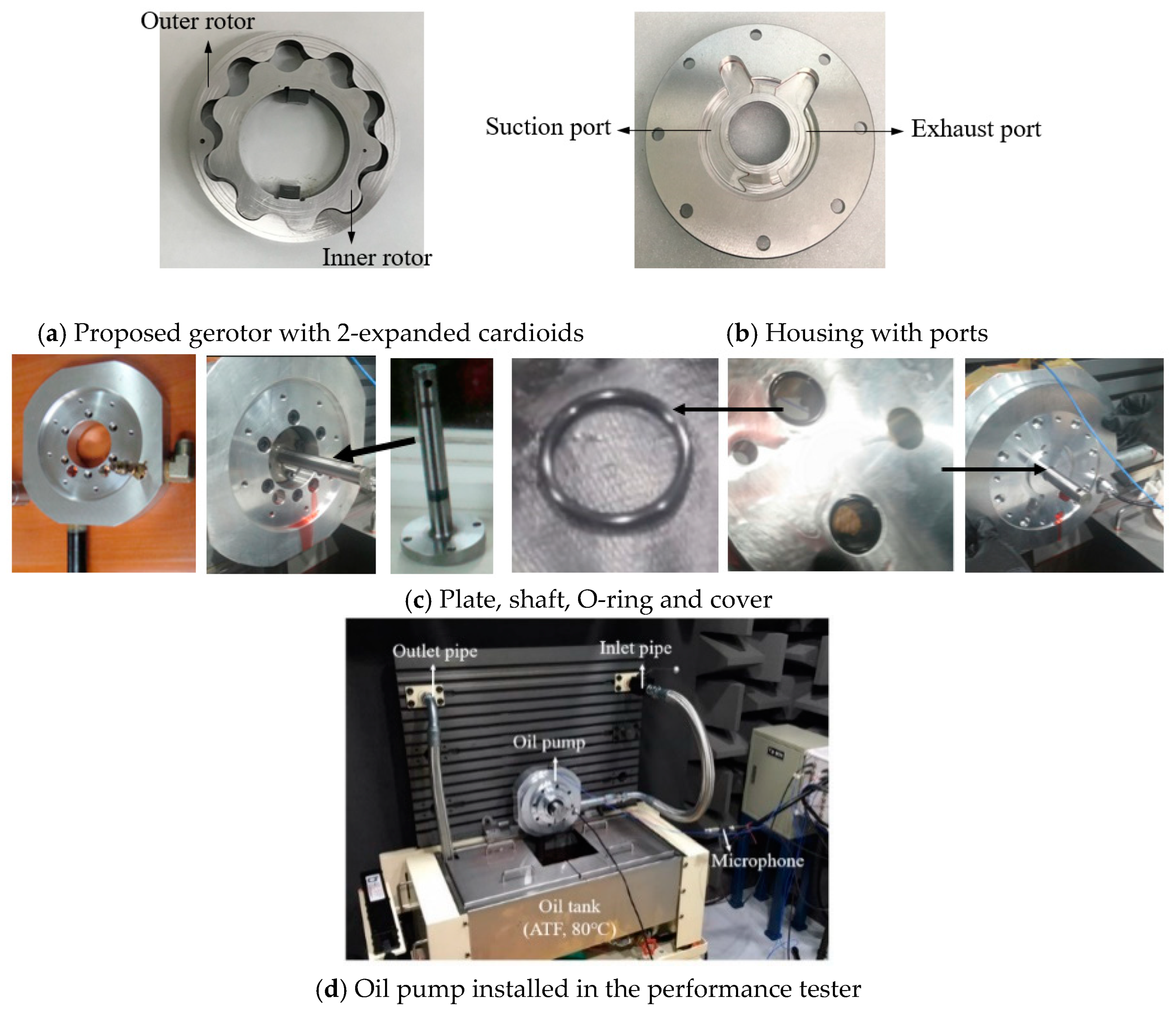
The geometry of the oil pump for fluid analysis consists of inner rotor, outer rotor, pumping chambers (which are cavities between the inner rotor and the outer rotor), suction/exhaust ports and inlet/outlet pipes as shown in Figure 14.
Since port shapes are determined by the gerotor profile, exact performances of the oil pump cannot be obtained without matching the port shape with the designed gerotor. Therefore, its design to be suitable for the proposed gerotor based on the accumulated experiences of the actual field was conducted according to the following procedures:
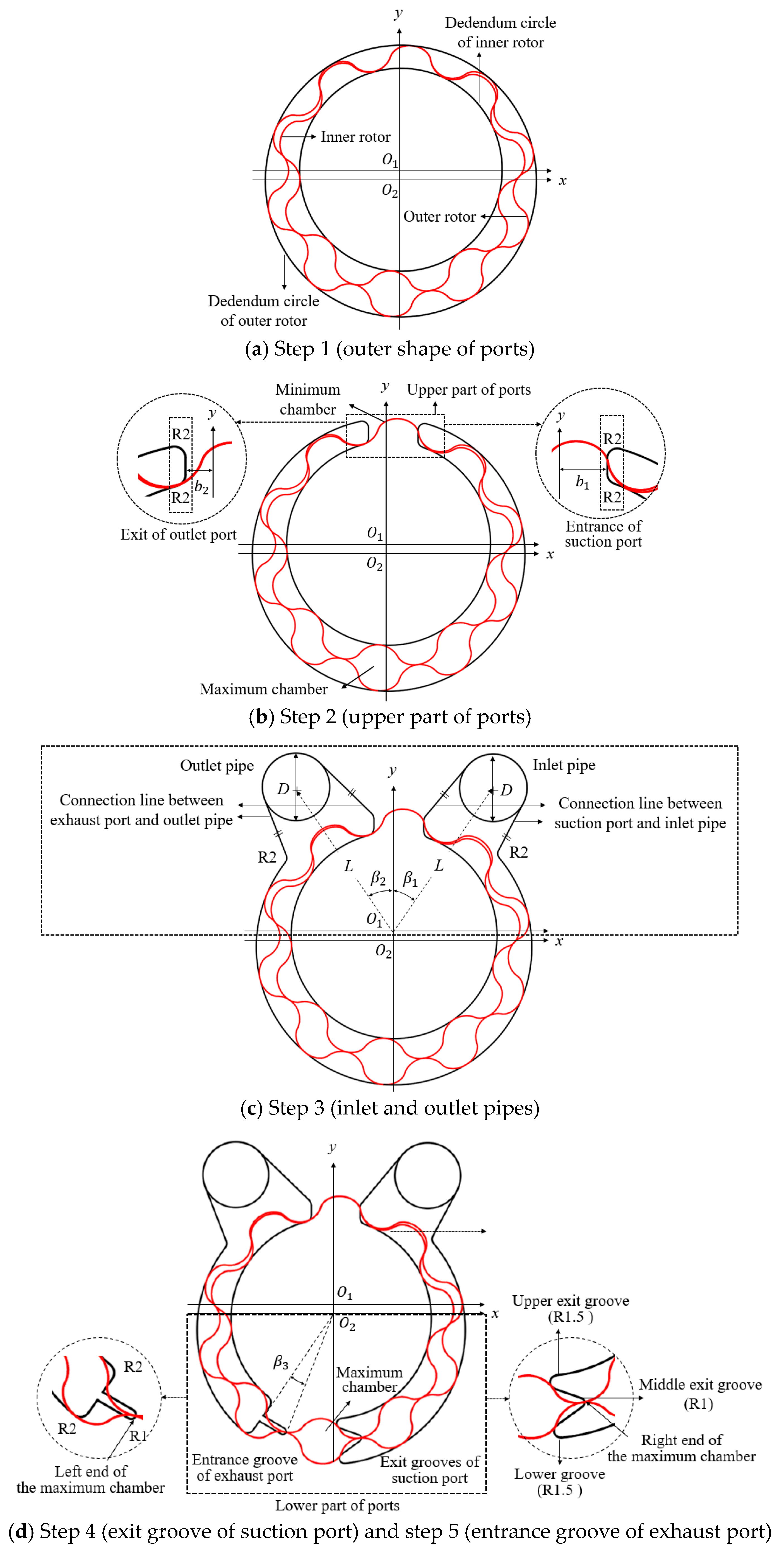
Step 1) Outer shape of ports: The inner diameter of the ports is to be the deddendum circle of the inner rotor, and the outer diameter is to be the deddendum circle of the outer rotor as shown in Figure 15a.
Step 2) Upper part of ports (entrance of the suction port and exit of the outlet port): When the pumping chambers have the maximum and minimum cavities, the entrance of the suction port starts ‘b1’ away from y-axis, and the exit of the outlet port ends ‘b2’ away from the –y-axis. Radii at the four edges of the upper part of the ports are 2 mm as shown in Figure 15b.
Step 3) Inlet and outlet pipes: The centers of the inlet and outlet pipes with diameter of ‘D’ rotated by ‘1’ and ‘-2’ from the y-axis on the center of the inner rotor (), respectively, and locate the distance of ‘L’ from ‘. The connection lines, which are tangent to the pipes and upper part of the ports, were generated as shown in Figure 15c, and the radii of the two connection edges are 2mm. ‘L’ (52.5 mm) and ‘D’ (20 mm) were determined by the size of the oil pump for six-speed automotive transmission,
Step 4) Exit grooves of suction port: When the maximum chamber is formed in the lower part of the ports, the upper and lower exit grooves of the suction port are generated to be tangent to the chamber with radii of 1.5 mm, and the middle groove with radius of 1 mm is on the right end of the maximum chamber, as shown in Figure 15d.
Step 5) Entrance groove of exhaust port: The entrance groove of the exhaust port is connected with a straight line between the arc with radius of 1 mm, which is on the left end of the maximum chamber, and the location ‘–3 ’ degree far from the arc, as shown in Figure 15d. The two radii of the edges are 2 mm.
‘1’, ‘2’, ‘3’, ‘b1’ and ‘b2’ were given from the dimension of the proposed gerotor with 2-expanded cardioids as shown in Table 5.
4. Prototyping and Performance Testing
A prototype of the new oil pump, composed of the proposed gerotor (SMR4040M), housing and cover (FC250) including the designed ports shapes, is shown in Figure 16. The NC lathe adjusted the inner diameters of the inner rotor (47 mm) and the outer diameter of the outer rotor (90 mm), and the wire electric discharge machine (EDM) fabricated lobe shapes within a tolerance below 0.01 mm. In order to install the components of the oil pump to the test equipment, the drive shaft to connect the driving motor with the gerotor was assembled with the plate. O-rings to prevent leakage of the working oil were inserted into the holes in the cover, which contacts with the inlet and outlet pipes, and the cover was bolted to the plate.
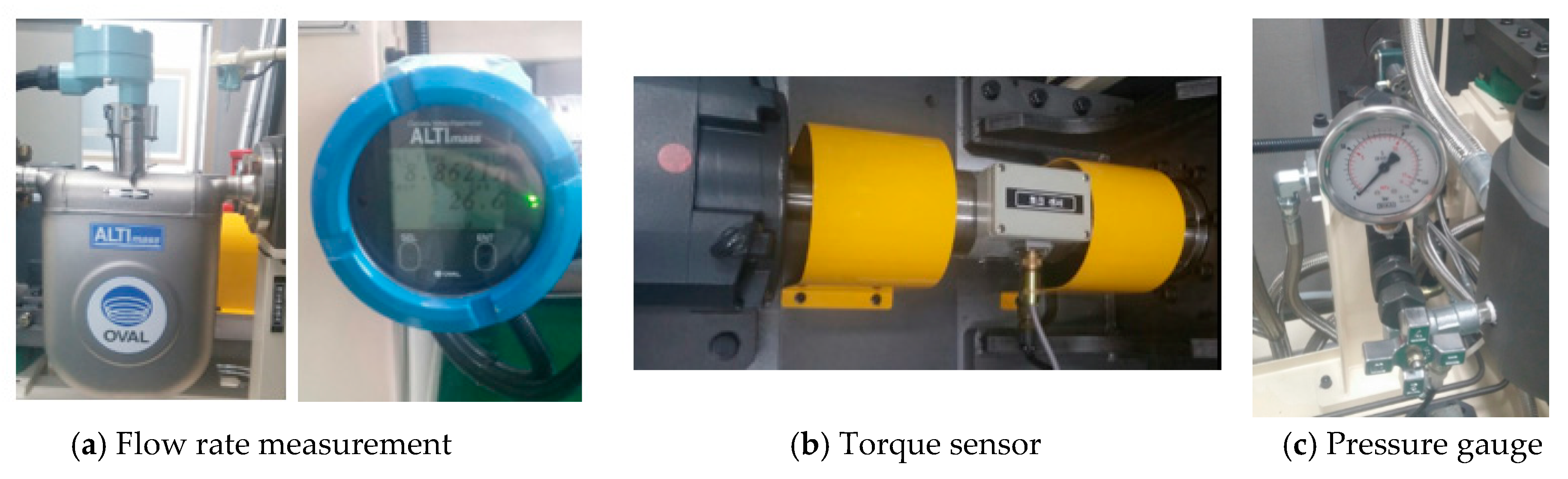
Performance tests were conducted to verify the excellence of the design methods for the proposed gerotor with 2-expanded cardioids and the port. Two identical prototypes were fabricated to ensure accuracy of the test results, and their average values were calculated. The gerotor was rotated by the power of the driving motor at an inner rotor rotational speed o, 2000 rpm ~ 3000 rpm which is the range to determine the performance of the oil pump in the actual field. The cooling water in the temperature control system maintained the temperature of the working oil constant (80 °C), and a microphone was placed 30 cm away from the oil pump. The flowrate measurement checked the amount of the exhausted working oil as shown in Figure 17a, and the torque sensor measured the driving torque of the motor as shown in Figure 17b. The pressure gauge showed the inlet and outlet pressures as shown in Figure 17c. When the driving motor rotates the gerotor, ATF with 0.1 MPa was taken in from the oil tank and transferred to the suction part of the oil pump, and it was exhausted through the outlet pipe at 1.6 MPa. Information of the measurement instruments are shown in Table 6.
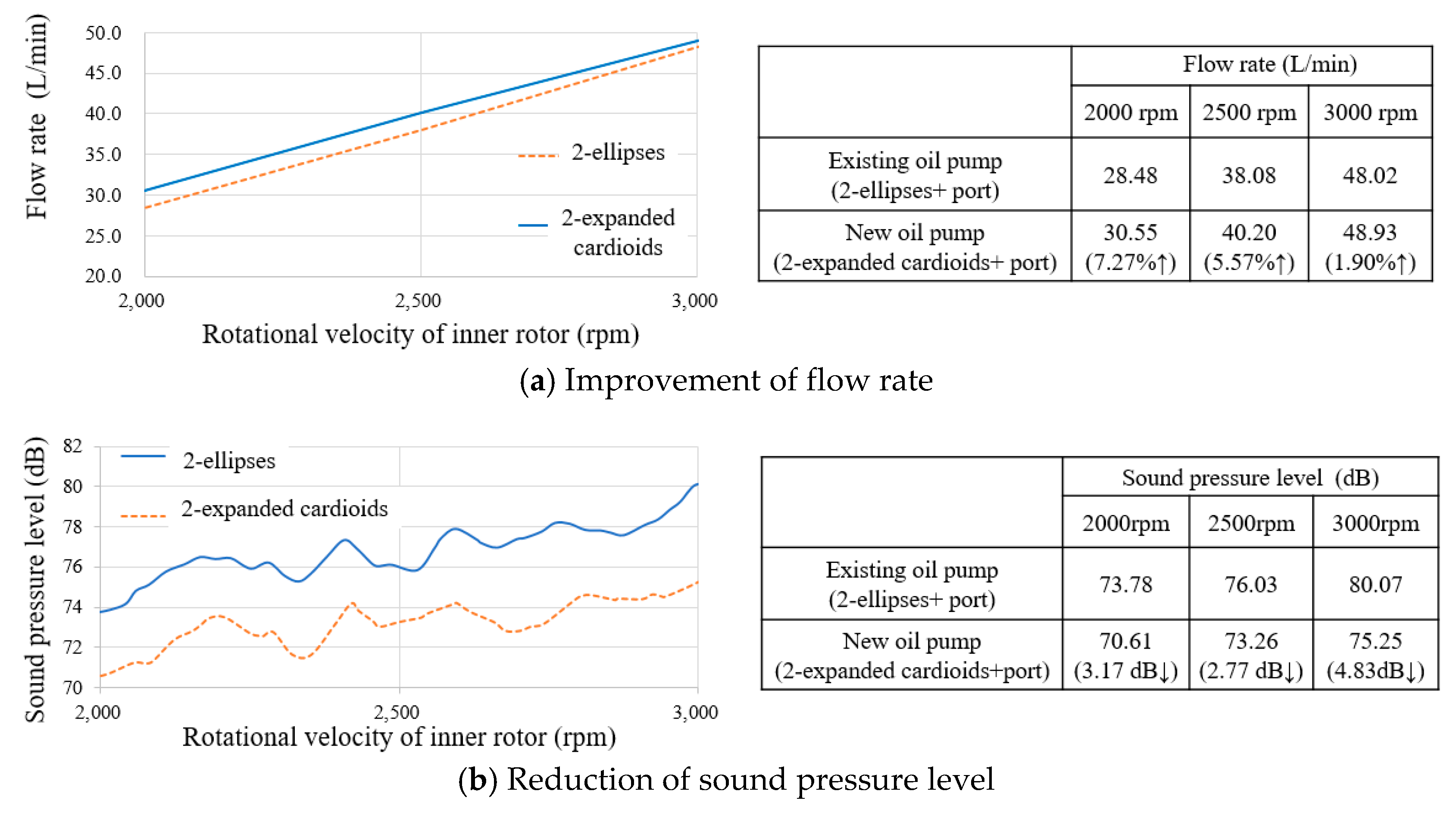
The flow rates and sound pressure levels of the new oil pump with the suggested gerotor and port shape and those of the existing one were plotted in Figure 18. The comparison results indicated that the proposed design of gerotor profile attributed to improvement of flow rate (7.29%~1.5%) and reduction of noise (2.77~4.83 dB), so noise reduction effects of design of the proposed gerotor and port on the performances were validated.
5. Conclusions
This study suggested a new gerotor lobe shape with 2-expanded cardioids to reduce the noise of the oil pump used in automatic automobile transmissions. Theoretical equations to generate the tooth profile with 2-expanded cardioids was established, and design of the gerotor was implemented through the automatic program. In addition, the design method of a port matching the suggested gerotor was introduced, and the performances of the new oil pump with the suggested gerotor and port shape were verified through the experimental test. Our conclusions are summarized as follows:
(1) In order to reduce the oil pump noise, a new lobe shape (2-expanded cardioids) was proposed by combining the two identical geometric curves (expanded cardioids1 and expanded cardioids 2, which are symmetric with respect to the x-axis), and theoretical equations to obtain the gerotor profile with the new lobe shape were established.
(2) An automatic program was developed to obtain the gerotor profile and to calculate the performances corresponding to the various input design parameters, and design of a gerotor with 2-expanded cadioids was conducted. The irregularity and maximum contact stress of the suggested model were decreased by 4.5% and 37.9%, respectively, compared to the existing (2-ellipses) gerotor.
(3) Design of a port shape suitable for the proposed gerotor with 2-expanded cardioids was performed according to the design method based on the accumulated actual field experiences.
(4) Based on the comparison results of the performance test of the new oil pump with that of the existing one (2000~3000 rpm), the flow rate was improved by 7.3%~1.5%, and the noise was reduced by 2.8 ~4.8 dB, and the design method for the gerotor with 2- expanded cardioids and port were validated.
The new lobe shape with 2-expanded cardioids and the port shape design method could be adopted in various fields, and it will contribute to improving the performance of oil pumps. In further research, an improved port shape design will be carried out to maximize the performance of the oil pump.
Author Contributions
S.H.L., H.S.K. and G.B.H. conceived design method/FEA, analyzed the data and performed the experiments; S.H.L. performed design and FEA; H.S.K. wrote the manuscript; G.B.H. assisted with FEA; C.K. was in charge of the whole trial. All authors read and approved the final manuscript.
Funding
This research was funded by the Basic Science Research Program through the National Research Foundation of Korea (NRF), funded by the Ministry of Education of the Korean government (NRF-2017R1D1A3A03000966, 2018R1A6A3A01011001). The authors gratefully acknowledge this support.
Acknowledgments
The authors would like to express gratitude to National Research Foundation of Korea (NRF) for funding and Samhan, Ltd. for critical discussion and technical assistance.
Conflicts of Interest
The authors declare no conflict of interest.
References
- Gamez Montero, P.J.; Castilla, R.; Codina, E.; Freire, J.; Morató, J.; Sanchez-Casas, E.; Flotats, I. GeroMAG: in-house prototype of an innovative sealed, compact and non-shaft-driven gerotor pump with magnetically-driving outer rotor. Energies 2017, 10, 435. [Google Scholar] [CrossRef]
- Mimmi, G.C.; Pennacchi, P.E. Non-undercutting conditions in internal gears. Mech. Mach. Theory 2000, 35, 477–490. [Google Scholar] [CrossRef]
- Gamez Montero, P.J.; Castilla, R.; Mujal, R.; Khamashta, M.; Codina, E. GEROLAB Package System: Innovative Tool to Design a Trochoidal-Gear Pump. J. Mech. Des. 2009, 131, 074502. [Google Scholar] [CrossRef]
- Ravari, M.K.; Forouzan, M.R.; Moosavi, H. Flow irregularity and wear optimization in epitrochoidal gerotor pumps. Meccanica 2012, 47, 917–928. [Google Scholar]
- Bonandrini, G.; Mimmi, G.; Rottenbacher, C. Design and simulation of meshing of a particular internal rotary pump. Mech. Mach. Theory 2012, 49, 104–116. [Google Scholar] [CrossRef]
- Om, I.L.; Ryo, S.I.; Kim, C.Y. Calculation for cross section and area efficiency of progressing cavity pump with hypotrochoidal multilobe using the differential geometric envelope approach. J. Pet. Sci. Eng. 2018, 171, 211–217. [Google Scholar] [CrossRef]
- Kwak, H.S.; Li, S.H.; Kim, C. Performance Improvement of Oil Pump by Design of Gerotor (Combined Profile-Two Ellipses) and Port. J. Korean Soc. Precis. Eng. 2016, 33, 207–216. [Google Scholar] [CrossRef]
- Bae, J.H.; Kwak, H.S.; San, S.; Kim, C. Design and CFD analysis of gerotor with multiple profiles (ellipse–involute–ellipse type and 3-ellipses type) using rotation and translation algorithm. Proc. Inst. Mech. Eng. Part C J. Mech. Eng. Sci. 2016, 230, 804–823. [Google Scholar] [CrossRef]
- Kwak, H.S.; Li, S.H.; Kim, C. Optimal design of gerotor (Ellipse1-Elliptical involute-Ellipse2 combined lobe shape) for improving fuel efficiency and reducing noise. J. Korean Soc. Precis. Eng. 2016, 33, 927–935. [Google Scholar] [CrossRef]
- Ding, H.; Visser, F.C.; Jiang, Y.; Furmanczyk, M. Demonstration and Validation of a 3D CFD Simulation Tool Predicting Pump Performance and Cavitation for Industrial Applications. J. Fluids Eng. 2011, 133, 011101. [Google Scholar] [CrossRef]
- Frosina, E.; Senatore, A.; Buono, D.; Olivetti, M. A Tridimensional CFD Analysis of the Oil Pump of an High Performance Engine. Energy Procedia 2014, 45, 938–948. [Google Scholar] [CrossRef]
- Kumar, M.S.; Manonmani, K. Computational fluid dynamics integrated development of gerotor pump inlet components for engine lubrication. J. Automob. Eng. 2010, 224, 1555–1567. [Google Scholar] [CrossRef]
- Hsieh, C.F.; Hwang, Y.W. Geometric Design for a Gerotor Pump with High Area Efficiency. J. Mech. Des. 2007, 129, 1269–1277. [Google Scholar] [CrossRef]
- Chang, Y.; Kim, J.; Jeon, C.; Kim, C.; Jung, S. Development of an Integrated System for the Automated Design of a Gerotor Oil Pump. J. Mech. Des. 2007, 129, 1099–1105. [Google Scholar] [CrossRef]
- Lee, M.C.; Kwak, H.S.; Seong, H.S.; Kim, C. A Study on Theoretical Flowrate of Gerotor Pump Using Chamber Areas. Int. J. Precis. Eng. Manuf. 2018, 19, 1385–1392. [Google Scholar] [CrossRef]
- Biernacki, K. Analysis of the material and design modifications influence on strength of the cycloidal gear system. Int. J. Precis. Eng. Manuf. 2015, 16, 537–546. [Google Scholar] [CrossRef]
- Giesbert, L.; Harald, N. Automotive Transmissions: Fundamentals, Selection, Design and Application; Springer Science & Business Media: Berlin/Heidelberg, Germany, 1999. [Google Scholar]
- Norton, M.P.; Karczub, D.G. Fundamentals of Noise and Vibration Analysis for Engineers, 2nd ed.; Cambridge University Press: Cambridge, UK, 2003. [Google Scholar]
- Stavytskyy, V.; Nosko, P.; Fil, P.; Karpov, A.; Velychko, N. Load-Independent Power Losses of Gear Systems: A Review. Teka Kom. Mot. I Energy Roln. 2010, 10B, 205–213. [Google Scholar]
Figure 1.
Comparison of the existing gerotor profiles.

Figure 2.
2-expanded cardiod profile.

Figure 3.
Definition of expanded cardioids.

Figure 4.
Generation of 2-expanded cardioids lobe shape.

Figure 5.
Orthogonal condition for finding the contact point.

Figure 6.
Contact points of a 2-expanded cardioids lobe shape.

Figure 7.
Inner and outer rotors profiles with 2-expanded cardioids lobe shape

Figure 8.
Schematic model for calculating pressure angle.

Figure 9.
Schematic model for calculating the Hertz contact stress.

Figure 10.
GUI to obtain gerotor profile and performance parameters.

Figure 11.
Calculation results obtained from the multiple calculation program.


Figure 12.
Comparison of maximum chamber areas between 2-ellipses and 2-expanded cardioids lobe shapes.
Figure 12.
Comparison of maximum chamber areas between 2-ellipses and 2-expanded cardioids lobe shapes.

Figure 13.
Comparison of curvature radii of 2-ellipses and 2-expanded cardioids lobe shapes.

Figure 14.
Analysis model of gerotor oil pump.

Figure 15.
Procedures to design ports.

Figure 16.
Prototype of the new oil pump.

Figure 17.
Measurements device.

Figure 18.
Comparison of the performances of the new oil pump and the existing one obtained from performance test.
Figure 18.
Comparison of the performances of the new oil pump and the existing one obtained from performance test.


Table 1.
Irregularities and contact stresses of the existing gerotors.
| Performance Parameter | 3-Ellipses | 2-Ellipses | Cardioid |
|---|---|---|---|
| Irregularity | 3.96 | 3.74 | 3.67 |
| Contact stress (MPa) | 142.14 | 113.51 | 91.03 |
Table 2.
Performance parameters of the proposed gerotor (2-expanded cardioids) and the existing gerotor (2-ellipses).
Table 2.
Performance parameters of the proposed gerotor (2-expanded cardioids) and the existing gerotor (2-ellipses).
| Lobe Type | 2-Ellipses | 2-Exanded Cardioids |
|---|---|---|
| Shape of gerotor |  |  |
| Flow rate (L/min) | 45.37 | 45.41 (0.1%↑) |
| Irregularity (%) | 3.74 | 3.57 (4.5%↓) |
| Specific slipping | 1.35 | 1.61 (19.3%↑) |
| Pressure angle (degree) | 18.39 | 28.56 (55.3%↑) |
| Contact stress (MPa) | 113.53 | 70.50 (37.9%↓) |
Table 3.
Comparison of largest and smallest flow rates at the maximum chamber.
| Lobe Type | Irregularity (%) | Largest Flow Rate (L/min) | SmallestFlow Rate (L/min) |
|---|---|---|---|
| 3-ellipses | 3.96 | 45.84 | 43.99 |
| 2-ellipses | 3.74 | 45.86 | 44.11 |
| Cardioid | 3.67 | 45.91 | 44.24 |
| 2-expanded cardioids | 3.57 | 45.86 | 44.33 |
Table 4.
Comparison of contact stress.
| Performance Parameter | 3-Ellipses | 2-Ellipses | Cardioid | 2-Expanded Cardioids |
|---|---|---|---|---|
| Contact stress (MPa) | 142.14 | 113.51 | 91.03 | 70.50 |
Table 5.
Design values to generate the ports for the proposed gerotor.
| β1 | β2 | β3 | b2 | b2 | D | L |
|---|---|---|---|---|---|---|
| 34° | 33.5° | 13° | 8.88 mm | 6.64 mm | 20 mm | 52.5 mm |
Table 6.
Measurement instruments.
| Item | Mass Flow Rate Meter | Torque Meter | Pressure Gauge | Microphone |
|---|---|---|---|---|
| Maker | OVAL | S. H. C | WIKA | PCB |
| Model No. | CA025L21SC22AA1132 | 48002V (5-2)-N-N-Z | A63ϕ-100k | 426E01 ICP 034899 |
| Accuracy | ±0.1% | ±0.2% | ±1.6% | < 0.05 dB |
© 2019 by the authors. Licensee MDPI, Basel, Switzerland. This article is an open access article distributed under the terms and conditions of the Creative Commons Attribution (CC BY) license (http://creativecommons.org/licenses/by/4.0/).
Share and Cite
MDPI and ACS Style
Lee, S.H.; Kwak, H.S.; Han, G.B.; Kim, C. Design of Gerotor Oil Pump with 2-Expanded Cardioids Lobe Shape for Noise Reduction. Energies 2019, 12, 1126. https://doi.org/10.3390/en12061126
AMA Style
Lee SH, Kwak HS, Han GB, Kim C. Design of Gerotor Oil Pump with 2-Expanded Cardioids Lobe Shape for Noise Reduction. Energies. 2019; 12(6):1126. https://doi.org/10.3390/en12061126
Chicago/Turabian StyleLee, Sang Hyeop, Hyo Seo Kwak, Gi Bin Han, and Chul Kim. 2019. "Design of Gerotor Oil Pump with 2-Expanded Cardioids Lobe Shape for Noise Reduction" Energies 12, no. 6: 1126. https://doi.org/10.3390/en12061126
Note that from the first issue of 2016, this journal uses article numbers instead of page numbers. See further details here.