Optimization Design of Oil-Immersed Air Core Coupling Reactor for a 160 kV Mechanical Direct Current Circuit Breaker


1
Hubei Provincial Key Laboratory for Operation and Control of Cascaded Hydropower Station, College of Electrical Engineering and New Energy, China Three Gorges University, Yichang 443002, China
2
School of Electrical engineering and Information, Wuhan Institute of Technology, Wuhan 430205, China
3
State Key Laboratory of Advanced Electromagnetic Engineering and Technology, Huazhong University of Science and Technology, Wuhan 430074, China
*
Author to whom correspondence should be addressed.
Energies 2019, 12(6), 1104; https://doi.org/10.3390/en12061104
Submission received: 19 January 2019
/
Revised: 6 March 2019
/
Accepted: 12 March 2019
/
Published: 21 March 2019
Abstract
:In this paper, the basic structure and design parameters of an oil-immersed air core coupling reactor were given according to the interruption requirement of the 160 kV mechanical direct current circuit breaker, and a field-circuit coupled finite element model was established based on the ANSOFT simulation platform. The prototype test results verified the correctness of the simulation calculation method. The coupling reactor design was optimized to minimize the total volume, taking equal height and heat flux design parameters as the optimization object, and the influence of the insulation distance between the oil tank and encapsulations on the secondary current of the coupling reactor were analyzed. Meanwhile, a combined optimization method about the reactor body and oil tank was proposed, and the optimization contour surface was plotted, which described the relationship between the total volume of the coupling reactor and structure parameters of the reactor body and oil tank. According to the optimization design results, the total volume was only 89% compared with the initial design parameters, and the correctness was verified by the simulation results.
1. Introduction
With the development of flexible direct current transmission technology and the progress in power electronics technology, high-voltage DC (direct current) transmission has been widely used in long-distance high power transmission, cable transmission, and non-synchronous communication of AC systems [1,2,3]. The circuit breaker is a key piece of equipment in direct current systems, and some direct current circuit breakers have been presented in [4,5]. A 160 kV mechanical direct current circuit breaker is proposed in [6,7] that has advantages of high breaking reliability, low loss, and low cost in comparison to traditional mechanical DC circuit breakers and hybrid DC circuit breakers. The coupling reactor plays an important role in the DC circuit breaker, but the design is difficult. The main reasons for this are: The primary and secondary side inductance, the coupling factor needs to simultaneously meet the requirements of the performance parameters, and the miniaturization design of the coupling reactor is needed due to the overall size limitations. Therefore, methods for optimizing the design of the coupling reactors are needed.
The oil-immersed air core reactor becomes the preferred type of coupling reactor due to its low electromagnetic interference and high insulation strength [8]. It mainly includes a reactor body and oil tank. For the reactor body, an optimization curve is given in Reference [9] that describes the percentage of the total volume over the minimum when the shape proportion deviates from the optimal value. In References [10,11,12], a combined thermal–electromagnetic optimization method is put forward, and the relationship between the volume of the reactor and geometric factors can be obtained under the conditions that the inductance and maximum temperature rise remain unchanged. In Reference [13], a magnetic particle layer is added outside of a conventional aluminum core to increase permeability, which can obviously reduce the volume of the reactor. However, the coupling factor is not included in References [9,10,11,12,13], so the above methods cannot be used directly in the design of a coupling reactor. In Reference [14], a design method for the coupling reactor is proposed that can realize the same thermal and stress distributions for the inner encapsulation, however this method is mainly concerned with the dry-type air core reactor. Regarding the oil tank, the finite element method (FEM) has been adopted to analyze the influence of the permeability and thickness of the shielding layer on the inductance [15,16], but the coupling factor has not been considered. Thus, the above optimization methods can only obtain locally optimal solutions.
In this paper, the structure type and initial parameters of an oil-immersed air core coupling reactor are given, and a field-circuit coupled finite element model is established based on the ANSOFT platform. The prototype test verified the correctness of the simulation calculation method. Meanwhile, taking the total volume of the coupling reactor as the optimization object, the influence of the oil tank parameters on the secondary current of the coupling reactor are analyzed, and a combined optimization method for the reactor body and oil tank is proposed. The optimization results show that it can significantly reduce the volume of the coupling reactor.
2. Design of the Reactor Body
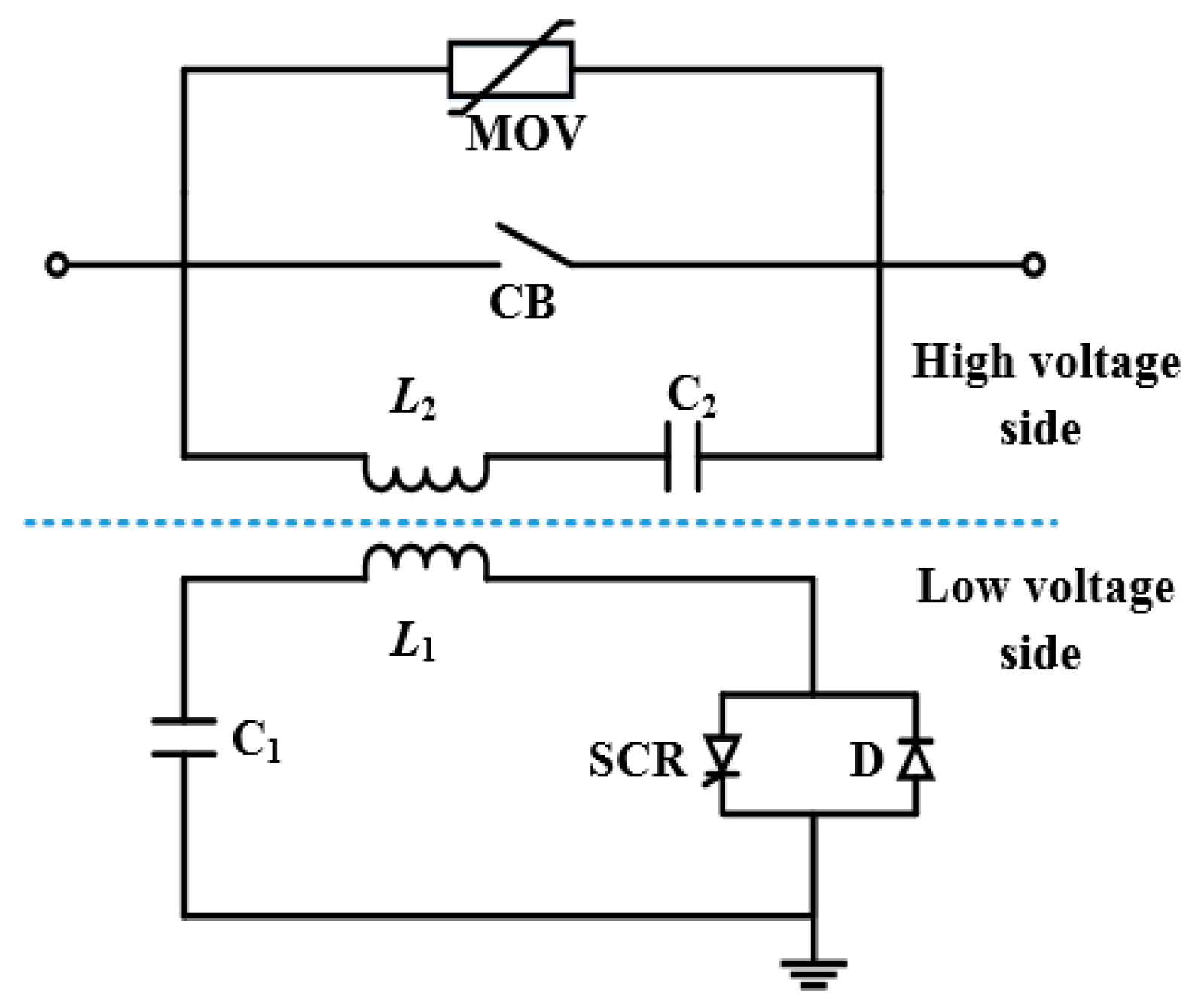
The topology structure of the 160 kV mechanical DC circuit breaker is shown in Figure 1, comprising of the high- and low-voltage sides. The high-voltage side was composed of the main through-flow branch (mechanical switching CB), converter branch (secondary inductance of the coupling reactor L2, capacitance C2), and energy-absorbing branch (arrester MOV). The low-voltage side consisted of the charging capacitor C1, primary inductance L1, and trigger switch module (thyristor SCR and antiparallel diode D).
The working principle of the DC circuit breaker was: When the direct current system is in normal operation, the CB is in the closed state. The current passes through the main through-flow branch. When the system needs to turn off the fault current, the SCR begins to conduct by the trigger signal, the high-frequency oscillation current is generated on the converter branch and is superposed with the direct current, and the current of the main through-current branch can be transferred to the converter branch rapidly, so the fault current can finally be turned off. A detailed description about the operation conditions is given in [17].
Taking the 160 kV flexible direct current transmission project as the research object, the data about the interruption capabilities and time of the direct current circuit breaker are given in [18]. Combined with the actual parameters of the power system, when the charging voltage of capacitor C1 is 45 kV, the secondary positive current peak amplitude of the coupling reactor needs to reach at least 9 kA, and the oscillation frequency is about 2000 Hz.
2.1. Basic Structure of the Reactor Body
The main parameters of the coupling reactor can be achieved according to the interrupting requirement of the DC current breaker, combined with the value of the capacitor and charging voltage. The primary and secondary side inductance were 0.5 mH and 8 mH, respectively, and the coupling factor was about 0.925. Meanwhile, the primary and secondary sides of the coupling reactor needed to withstand 160 kV DC voltage for a long period of time and withstand 320 kV DC voltage for a short period of time.
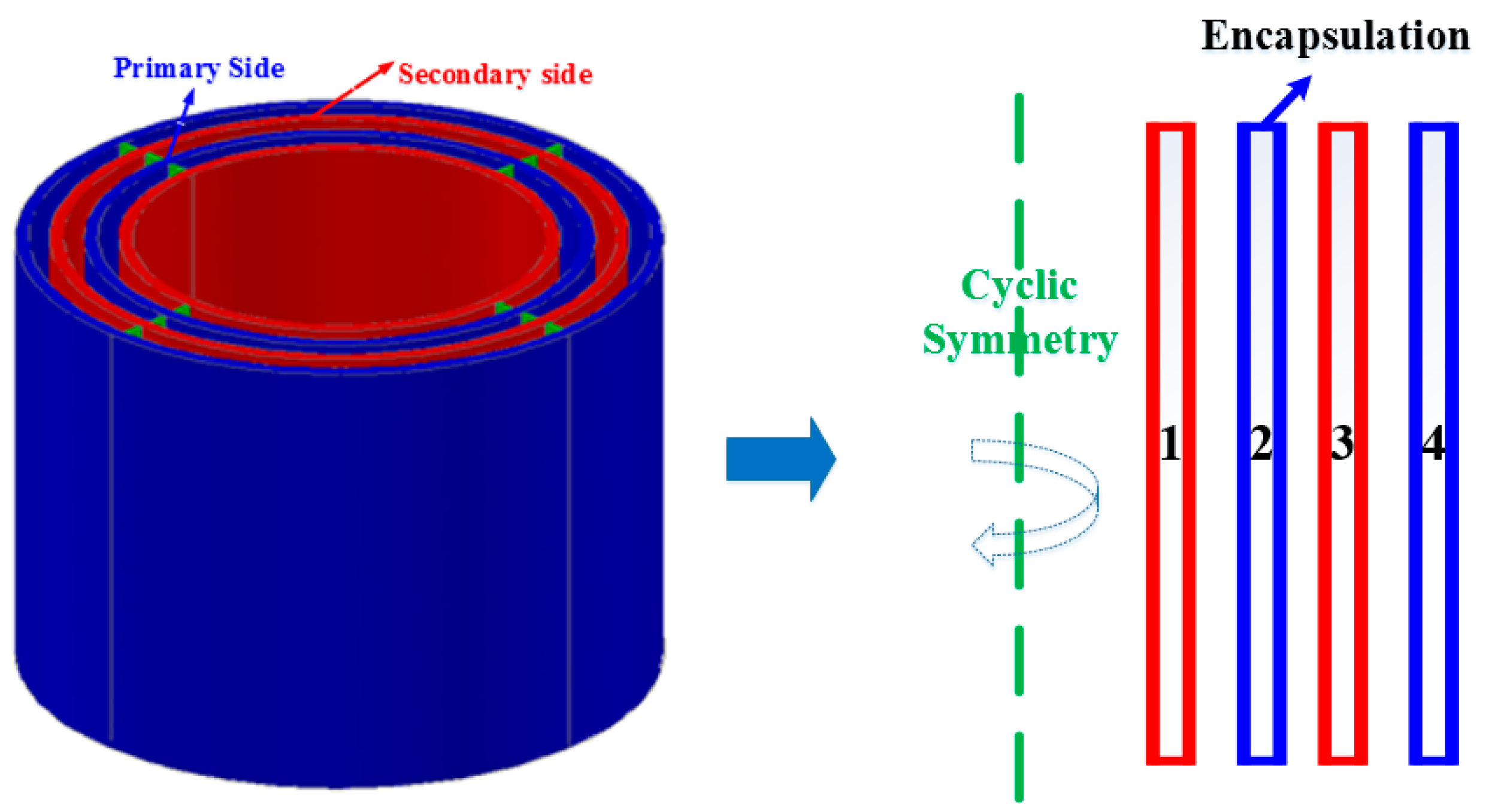
The basic structure of the reactor body was proposed by considering the demands of the coupling factor and insulation. The reactor body adopted a multi-encapsulation parallel structure, each encapsulation was arranged alternately—encapsulations 2 and 4 made up the primary side, and encapsulations 1 and 3 constituted the secondary side of the coupling reactor, as shown in Figure 2.
2.2. Design Method
The primary and secondary side inductance needed to meet the parameters demand of the coupling reactor. The equation constraint condition can be written as [19,20]:
Here, and are the turn number and current of encapsulation , , and are the inductance of the primary and secondary sides; and are the total current of the primary and secondary sides; is the encapsulation number; and is the mutual inductance geometric coefficient.
The equal height and heat flux heat design method was adopted in the design of the coupling reactor. When adopting this method, the encapsulation height, current density, and thermal and stress load distribution of each encapsulation were basically the same, thus the carrying current capacity of the coupling reactor could be fully utilized. The constraint condition equation is [21,22,23]:
where and are the conductor cross section and height of encapsulation , respectively. Combined with Equations (1) and (2), the total constraint conditions for the reactor body can be written as:
For a given encapsulation height and encapsulation number, the initial design parameters of the reactor body can be obtained, and the mutual inductance between the primary and secondary side can be calculated.
The coupling factor is defined as [24]:
where, is the mutual inductance matrix, is the mutual inductance between primary and secondary sides, and is the coupling factor.
The initial parameters of the reactor body were selected, the inner radius was 0.36 m, the distance between the encapsulations was 0.049 m considering the insulation requirements, and the metal conductor material was copper. Combined with Equations (1) and (5), when the encapsulation height was equal to 1.2 m, the coupling factor was 0.925, and the primary and secondary side inductances were 0.5 mH and 8 mH, respectively.
2.3. Simulation Results
According to the above design results, a field-circuit coupled finite element model was established based on the ANSOFT simulation platform. Considering calculation accuracy and calculation time, some simplifications and equivalencies were made. The geometry mode selected “Cylindrical about Z” in the ANSOFT, so the actual structure of the reactor body could be equivalent to a 2D model, and the height, radial width, and turn number of encapsulations were equal to the actual design parameters. The whole computational domain was 3 times the radial length and 3 times the axial height of the reactor in the model. The equivalent model of the reactor body is shown in Figure 3.
The circuit model is shown in Figure 4, including capacitors C1, C2, and the coupling reactor, and the inductance corresponds to the encapsulations coils in the reactor body.
The governing equation, boundary conditions, and mesh generation are essential to the simulation calculation.
(1) Governing equation
The filed-circuit coupled was calculated by the magnetic field and circuit control equation [25,26,27], the eddy current of encapsulations could be ignored as the encapsulation coils were made of thin wire, thus, the vector magnetic potential, , can be written as:
The current density of each encapsulation can be calculated, as shown in Equation (7):
where, is the permeability and is the current density of encapsulation .
In the circuit model, the control equation is:
where, and are the resistance and flux linkage of encapsulation , is the encapsulation voltage, and is the conductor section area.
(2) Boundary conditions
The boundary conditions are essential, and were set as follows: The left boundary line of the model was set as the odd symmetry, and the upper, lower, and right boundary lines were set as balloon boundaries.
(3) Mesh generation
The mesh generation density directly affects calculation time and calculation accuracy. The mesh increased in density as it neared the encapsulations and was relatively sparse when the region was far away from the reactor body.
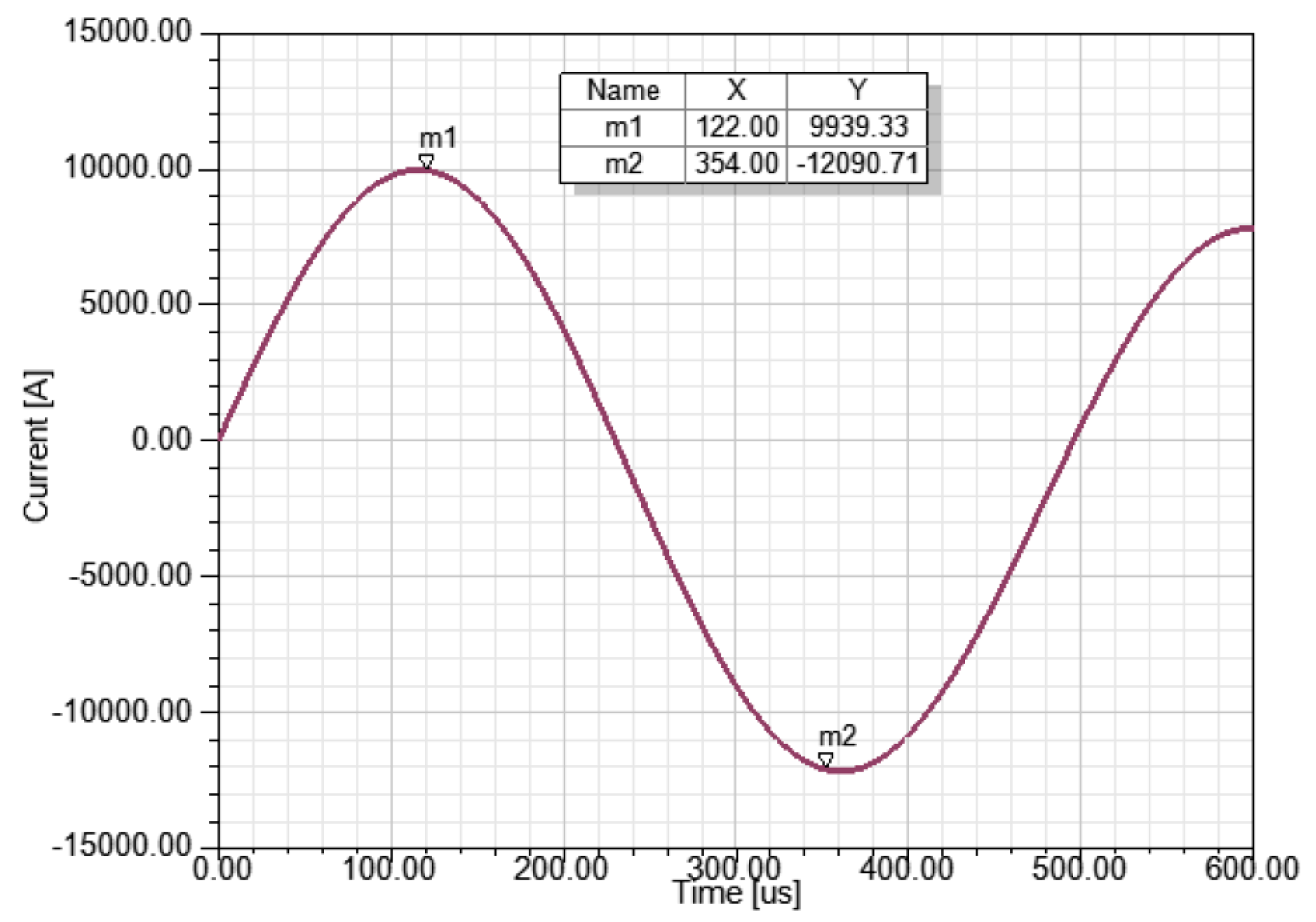
The value of the capacitance C1 and C2 are 135 μF and 10 μF, and the calculation time was set as 600 μs. According to the above calculation method, when the charging voltage of capacitor C1 is 45 kV, the secondary side current waveform of the coupling reactor can be obtained, as shown in Figure 5.
In Figure 5, it can be seen that the peak amplitude of the positive and negative currents are 9.94 kA and 12.09 kA, respectively, and the oscillation frequency was 2020 Hz.
3. Design of the Oil Tank
The oil tank is an important component of the coupling reactor. The eddy current generated by the oil tank can affect the secondary side current, thus, the influence of the oil tank should be considered in the design of the coupling reactor.
3.1. Initial Parameters of the Oil Tank
The oil tank is located on the outside of the reactor body, and can be equivalent to a 2D symmetry model. The insulating oil is around the encapsulations, which plays the role of insulation and heat dissipation. The equivalent model of the oil tank and reactor body is shown in Figure 6.
The initial design parameters of the oil tank are: The insulation distances between the oil tank and encapsulations were 250, 225, and 650 mm on the lower, right, and upper sides, respectively, and the material of the oil tank was steel. The thickness of the oil tank was 20, 10, and 20 mm.
3.2. Simulation and Test Results
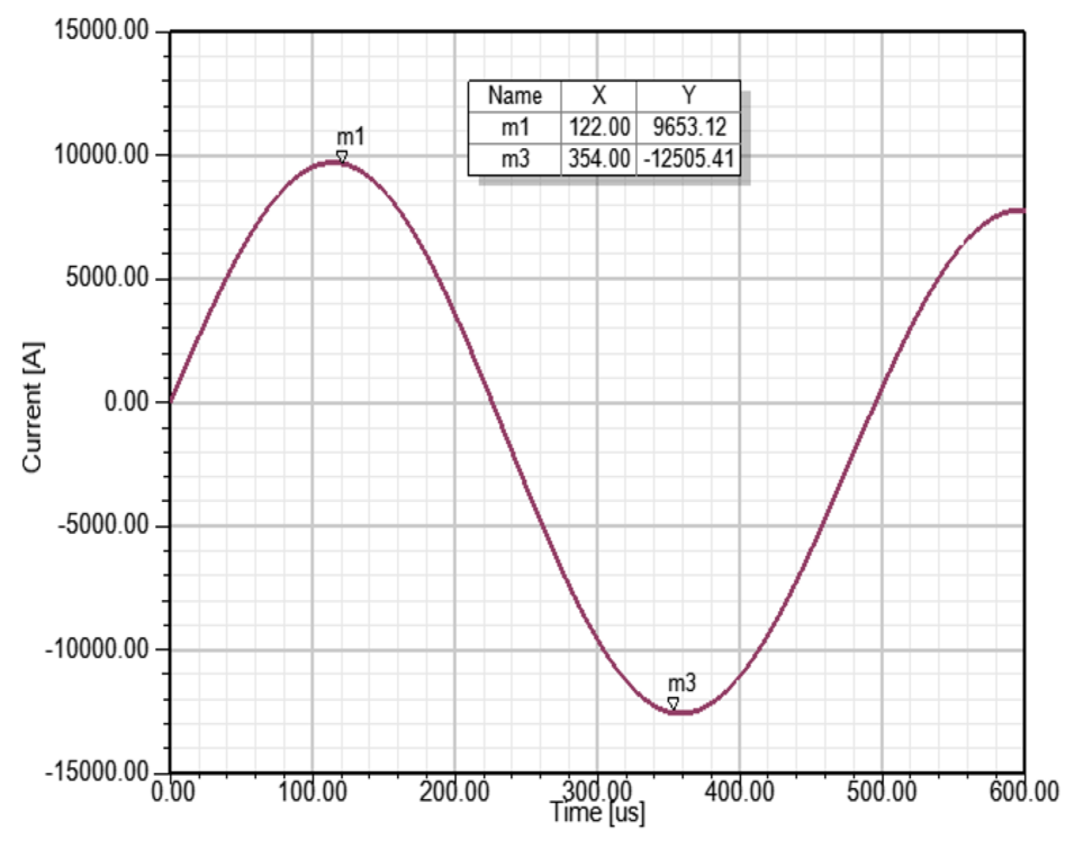
Simulation results: The eddy current of the oil tank was considered in the field-circuit coupled simulation calculation. When the charging voltage of capacitor C1 was 45 kV, the secondary side current waveform of the coupling reactor could be achieved as shown in Figure 7.
In Figure 7, the peak amplitude of the positive and negative current are 9.65 kA and 12.51 kA, respectively, and the oscillation frequency was 2024 Hz. The values were basically the same, as in the situation without the oil tank. Thus, it can be said that the oil tank affects the primary and secondary side inductance and coupling factor simultaneously, which results in the secondary side current of the coupling reactor being basically the same.
The prototype of the coupling reactor was developed, as shown in Figure 8. The test was done with the converter circuit and the charge voltage of capacitor C1 gradually increased from 3 kV to 28 kV.
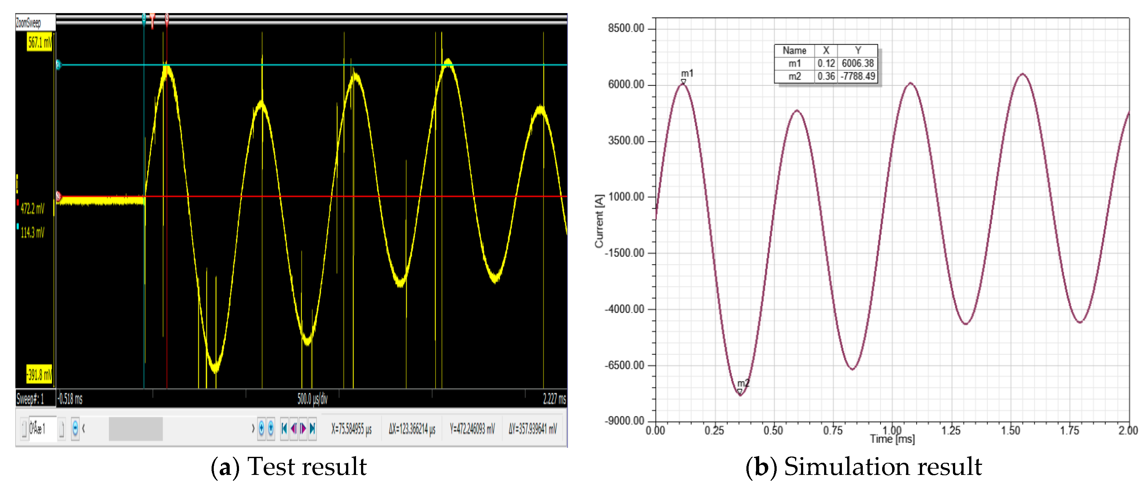
In the actual measurement process, the secondary side current of coupling reactor was converted into voltage signal, so the voltage waveform are the same as the secondary side current, and it only needed to multiply the convert coefficient. When the charge voltage of capacitor C1 was 28 kV, the test result is given in Figure 9a, meanwhile, the simulation result was also given, as shown in Figure 9b, showing that the waveforms are basically the same.
The error factor between the simulation and test results is given in Table 1, according to the secondary side current waveform, the test results showed that the error factor of the positive and negative side current amplitude, and frequency were less than 3.3% compared with the simulation results. This is relatively small and can be ignored, it can be regarded that the test results verify the correctness of the simulation calculation method.
3.3. The Influence of the Oil Tank on the Coupling Reactor
The insulation distance between the oil tank and encapsulations directly affect the total volume of the coupling reactor, according to the insulation demand, the relative distances were selected as 0.9, 1, 1.1, 1.2, and 1.3 times the initial parameters. The secondary side current and oscillation frequency were given as shown in Table 2.
In Table 2, the peak amplitude of the positive and negative current is basically the same with the different distance, and the maximum error factor was only 2%, compared with the initial parameters.
4. The Combined Optimization Method for the Reactor Body and Oil Tank
The optimization object was to realize the minimum total volume, with the precondition that the secondary side current of the coupling reactor must meet the interruption requirement of the DC circuit breaker.
According to the equivalent model of the coupling reactor, the total volume can be written as:
where, and are the radius and height of the oil tank respectively.
The radius and height of the oil tank can be calculated by Equation (10).
where, , , and are the distance between the reactor body and oil tank from the upper, lower, and right sides, and is the thickness of the reactor body.
The encapsulation width is basically the same based on the equal height and heat flux design method, so the thickness of the reactor body can be written as:
where, is the radial width of the encapsulation and is the distance between encapsulations. Assuming that parameter remains unchanged as the insulation limitation, it can be derived that the thickness of the reactor body is constant when the value of is larger than .
4.1. Realization of the Optimization Method
The primary and secondary side inductance and coupling factor are the main parameters for the coupling reactor. The curve between the inner radius, encapsulation height of the reactor body, and the coupling factor can be plotted based on the equal height and heat flux design method, as shown in Figure 10 and Figure 11.
In Figure 10 and Figure 11, it can be seen that that the coupling factor gradually increased with the increase of the inner radius and encapsulation height. Thus, there exists an optimal structure size to realize the miniaturization of the coupling reactor.
The inner radius and encapsulation height should be simultaneously adjusted to meet the inductance and the coupling factor, and so the fitted curve between the inner radius and encapsulation height can be plotted.
In Figure 12, it is shown that the encapsulation height gradually decreased with the increasing inner radius, and the quadratic fit relational expression could be achieved as shown in Equation (12):
Suppose a variable in the initial design is , which is selected as the normalized standard, and the corresponding variable in a new design is . Then, the proportionality factor is defined as [10].
From Equations (9)–(12), the proportionality factor of the total volume can be written as:
According to the initial design parameters of the reactor body and oil tank, the proportionality factor of volume can also be written as:
where, , , and are the proportionality factors of total volume, inner radius, and insulation distance between the oil tank and encapsulations, respectively.
4.2. Optimization Design Results
The optimization contour surface can be plotted from Equation (14), which describes the relationship between the total volume and inner radius, and insulation distance, as shown in Figure 13, where the ranges of and are 0.8–1.2 and 0.9–1.3, respectively.
In Figure 13, it can be seen that the total volume of the coupling reactor gradually increased with the increasing , and there was a minimum value when = 1.15 and = 0.9. At this point, the volume was about 89% compared with the initial design parameters.
The overall optimization flow chart is shown in Figure 14.
According to the initial parameters of the reactor body and oil tank, the optimization design results can be obtained based on the optimization contour surface, as shown in Table 3.
4.3. Simulation Verification
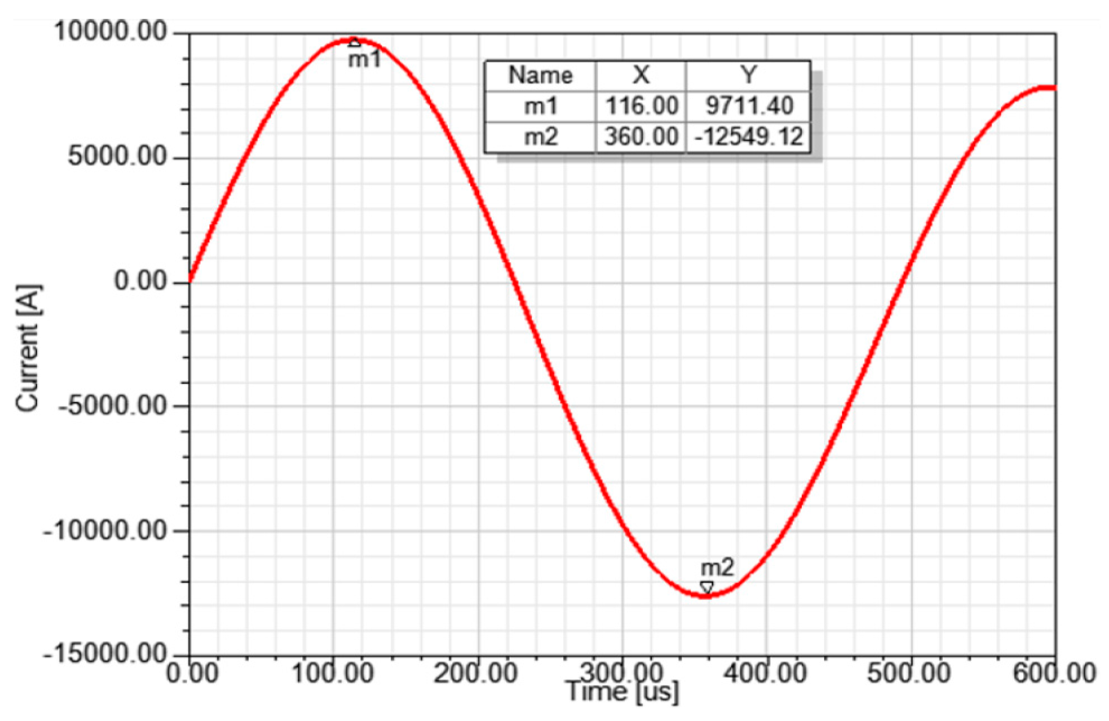
In order to verify the correctness of the optimization design results, a field-circuit coupled finite element model was established. When the charging voltage of capacitor C1 was 45 kV, the secondary side current of the coupling reactor could be obtained, as shown in Figure 15.
In Figure 15, it can be seen that the peak amplitude current of the positive and negative was 9.71 kA and 12.55 kA, respectively, and the oscillation frequency was 2000 Hz, which meets the interrupting requirements of the DC circuit breaker.
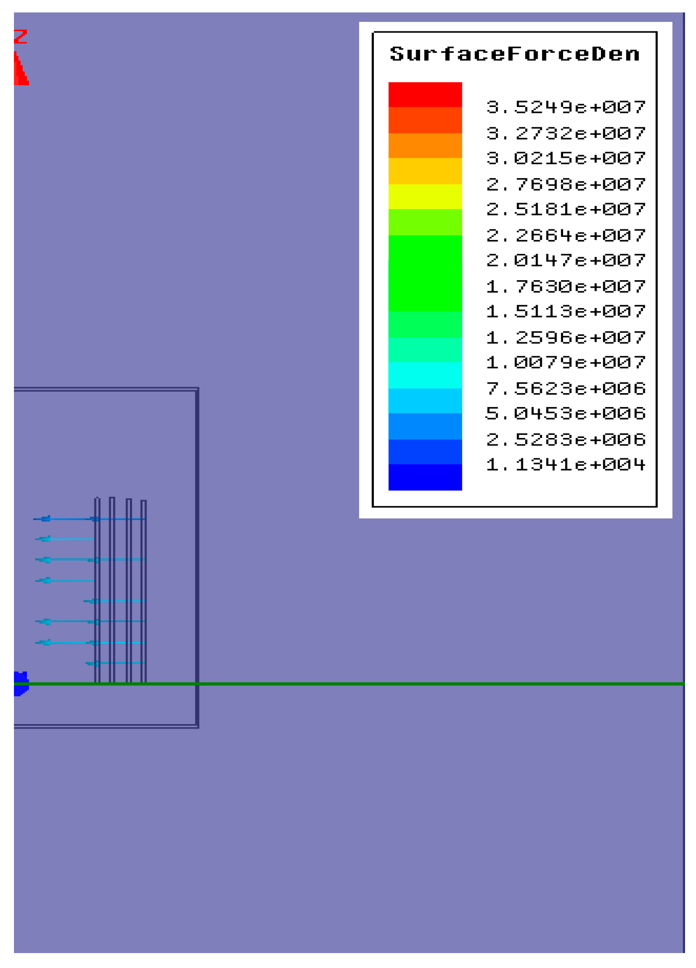
The magnetic field and stress distribution of the coupling reactor could be achieved when the secondary side current reached peak amplitude, as shown in Figure 16 and Figure 17.
Figure 16 and Figure 17 show that the maximum magnetic flux density was 0.55 T, concentrated mainly on the inner side of the oil tank. This can mainly be attributed to the effects of the oil tank eddy current. Meanwhile, the maximum surface force density of the encapsulations was 35.2 MPa, which is significantly less than the limit of the metal conductor material. Thus, the simulation results verify the correctness of the optimization design method.
5. Conclusions
The structure type and initial design parameters of the oil-immersed air core coupling reactor were given, and a field-circuit coupled finite element model was established based on the ANSOFT simulation platform. The prototype test verified the correctness of the simulation calculation method, and the following conclusions can be made:
- The oil tank affects the primary and secondary side inductance and coupling factor simultaneously, thus the secondary side current of the coupling reactor could also meet the interruption requirement of the DC circuit breaker.
- A combined optimization method about the reactor body and oil tank was proposed, and the results showed that the volume of the coupling reactor was only 89% compared with the initial design parameters, it can significantly reduce the total volume, and the correctness is verified by the simulation results.
- The optimization design about reactor body and oil tank was mainly focused on the given parameters of the coupling reactor in the later stage. The parameters optimization about the coupling reactor should also be considered in order to reduce the volume.
Author Contributions
Methodology, F.Y. and Z.Y.; validation, B.T., C.D., S.Q. and L.H.; writing—original draft, F.Y.
Funding
This research was funded by Hubei Provincial Key Laboratory for Operation and Control of Cascaded Hydropower Station, China Three Gorges University (No.2018KJX09).
Conflicts of Interest
The authors declare no conflict of interest.
References
- Tang, G.; Luo, X.; Wei, X. Multi-Terminal HVDC and DC-Grid Technology. Proc. CSEE 2013, 33, 8–17. [Google Scholar]
- Franck, C.M. HVDC Circuit Breakers: A Review Identifying Future Research Needs. IEEE Trans. Power Deliv. 2011, 26, 998–1007. [Google Scholar] [CrossRef] [Green Version]
- Li, Y.; Luo, Y.; Xu, S.; Zhou, Y.; Yuan, Z. VSC-HVDC Transmission Technology: Application, Advancement and Expectation. South. Power Technol. 2015, 9, 7–13. [Google Scholar]
- Liu, S.; Popov, M. Development of HVDC system-level mechanical circuit breaker model. Int. J. Electr. Power Energy Syst. 2018, 103, 159–167. [Google Scholar] [CrossRef]
- Liu, S.; Liu, Z.; Chavez, J.; Popov, M. Mechanical DC circuit breaker model for real time simulations. Int. J. Electr. Power Energy Syst. 2019, 107, 110–119. [Google Scholar] [CrossRef]
- Chen, M.; Xu, H.; Zhang, Z. Design and Simulation of Coupling Mechanical High Voltage DC Circuit Breaker. High Volt. Eng. 2018, 44, 380–387. [Google Scholar]
- Zhang, Z.; Li, X.; Chen, M. Research and Development of 160kV Ultra-Fast Mechanical HVDC Circuit Breaker. Power Syst. Technol. 2018, 42, 2331–2338. [Google Scholar]
- Liu, K.; Yang, Y.; Shang, T. Research of the Inductance Calculation for Air-core Magnetic Shielding Reactor. High Volt. Appar. 2016, 52, 74–77. [Google Scholar]
- Huang, J.; Xiao, Z.; Chen, G. The Calculation and Design of Air Core Reactor. Electric. Drive. 1991, 5, 46–55. [Google Scholar]
- Yuan, F.; Yuan, Z.; Wang, Y.; Liu, J.; Su, H.; He, J. Research of Electromagnetic and Thermal Optimization Design on Air Core Reactor. IEEJ Trans. Electric. Electron. Eng. 2018, 13, 725–731. [Google Scholar] [CrossRef]
- Yuan, F.; Yuan, Z.; Chen, L.; Wang, Y.; Liu, J.; He, J.; Pan, Y. Thermal and Electromagnetic Combined Optimization Design of Dry Type Air Core Reactor. Energies 2017, 10, 1989. [Google Scholar] [CrossRef]
- Yuan, Z.; He, J.J.; Pan, Y.; Yin, X.G.; Luo, C.J.; Chen, S.Z. Research on Electromagnetic Efficiency Optimization in the Design of Air Core Coils. Int. Trans. Electr. Energy Syst. 2015, 25, 789–798. [Google Scholar] [CrossRef]
- Luo, L.; Zhao, S.; Xu, J. Design of Large Inductance Power Cable. High Volt. Eng. 2015, 41, 2635–2642. [Google Scholar]
- Yuan, Z. Research of Thermal and Electromagnetic Optimization Design on Air Core Power Reactors with Paralleled Cylindrical Coils; Huazhong University of Science and Technology: Wuhan, China, 2014. [Google Scholar]
- Zhang, H.; Lin, Y.; Zhang, B. Magnetic Shielding Research of Air-Core Reactor Based on Ansoft. Electr. Locomotives Mass Transit. Veh. 2014, 37, 38–41. [Google Scholar]
- Zhang, O.; Quanfeng, L.; Yichao, L. Study on Power Frequency Magnetic Field Shielding Method of Dry Air-core reactor. Power Capacit. React. Power Compens. 2013, 34, 66–73. [Google Scholar]
- Huang, R.; Zhu, Z.; Chen, J. Research and Experimental Validation of Control and Protection Strategy of HVDC Circuit Breaker in Fault Condition Application in Nan’ao Multi-Terminal VSC-HVDC System. Power Syst. Technol. 2018, 42, 2339–2345. [Google Scholar]
- Pan, Y.; Yuan, Z.; Chen, L. Research on the Coupling Mechanical High Voltage DC Circuit Breaker. Proc. CSEE 2018, 38, 7113–7120. [Google Scholar]
- Li, Y.; Zhang, Z.; Li, L.; Li, G.; Jiang, M. Calculation and Design of Dry type Air core Reactor. Energy Power Eng. 2013, 5, 1101–1104. [Google Scholar] [CrossRef]
- Zhao, Y.; Kang, B.; Ma, X. Optimization Model of Dry Type Air-Core Reactor Based on Balance of Additional Constraints. Trans. China Electrotech. Soc. 2010, 25, 80–84. [Google Scholar]
- Yuan, F.; Yuan, Z.; Wang, Y.; Liu, J.; He, J.; Pan, Y. Thermal Optimization for Nature Convection Cooling Performance of Air Core Reactor with the Rain Cover. IEEJ Trans. Electric. Electron. Eng. 2018, 13, 995–1001. [Google Scholar] [CrossRef]
- Yuan, F.; Yuan, Z.; Liu, J. Research on Temperature Field Simulation of Dry Type Air Core Reactor. In Proceedings of the International Conference on Electrical Machines and Systems (ICEMS), Sydney, Australia, 11–14 August 2017. [Google Scholar]
- Yuan, F.; Wu, K.; Yuan, Z. Thermal Optimization for Dry Type Air Core Reactor Base on FEM. In Proceedings of the International Conference on Electrical Machines and Systems (ICEMS), Jeju, Korea, 7–10 October 2018. [Google Scholar]
- Hu, Y.Q.; Chen, F.Z.; Ye, B. Electromagnetism and Electrodynamics; Science Press: Beijing, China, 2008. [Google Scholar]
- Yan, Q.Q.; Shu, N.Q.; Guan, X.Y.; Jin, X.; Hang, C.C. Calculation of Short-circuit Electric Force of Dry-type Air core Reactor Based on Electromagnetic-structural Coupling Method. Water Resour. Power 2016, 34, 186–189. [Google Scholar]
- Chen, R.; Wang, S.; Li, Y. Electromagnetic-fluid-temperature Coupling Calculation and Analysis of Dry-type Air-core Shunt Reactor. High Volt. Eng. 2017, 43, 3021–3028. [Google Scholar]
- Wang, Z.; Yin, Z.; Wu, L. Study on Field-Circuit Coupling Model of Saturated Reactor Based on Finite Elements Theory. In Proceedings of the International Conference on Energy and Environment Technology, Shenzhen, China, 16–18 October 2009. [Google Scholar]
Figure 1.
The topology structure of the mechanical DC circuit breaker.

Figure 2.
The basic structure of the reactor body.

Figure 3.
The equivalent model of the reactor body.

Figure 4.
The circuit model.

Figure 5.
The secondary side current waveform.

Figure 6.
The equivalent model of the oil tank and reactor body.

Figure 7.
The secondary side current waveform with the oil tank.

Figure 8.
The prototype of the coupling reactor.

Figure 9.
The test and simulation results of the secondary side current.

Figure 10.
The curve between the encapsulation height and coupling factor (inner radius = 0.36 m).

Figure 11.
The curve between the inner radius and coupling factor (encapsulation height = 1.2 m).

Figure 12.
The fitted curve between the inner radius and encapsulation height.

Figure 13.
The optimization contour surface between the total volume and the inner radius and insulation distance.
Figure 13.
The optimization contour surface between the total volume and the inner radius and insulation distance.

Figure 14.
The overall optimization flow chart.

Figure 15.
The secondary side current waveform with the optimization method.

Figure 16.
The magnetic field distribution of the coupling reactor.

Figure 17.
The surface force density distribution of the coupling reactor.


Table 1.
The test and simulation results.
| Parameters | Positive Current (kA) | Negative Current (kA) | Frequency (Hz) |
|---|---|---|---|
| Simulation results | 6.01 | 7.79 | 2024 |
| Test results | 5.90 | 7.55 | 1961 |
| Error factor | 1.86% | 3.18% | 3.21% |
Table 2.
The current and frequency with different distances between the oil tank and encapsulations.
Table 2.
The current and frequency with different distances between the oil tank and encapsulations.
| Relative Distance | 0.9 | 1 | 1.1 | 1.2 | 1.3 |
|---|---|---|---|---|---|
| Positive current (kA) | 9.50 | 9.65 | 9.74 | 9.79 | 9.82 |
| Negative current (kA) | 12.55 | 12.51 | 12.43 | 12.37 | 12.32 |
| Frequency (Hz) | 2032 | 2024 | 2020 | 2016 | 2016 |
Table 3.
The optimization design results of the reactor body and oil tank.
| Parameter | The Initial Parameter | The Optimization Parameter |
|---|---|---|
| Inner radius of the reactor body (m) | 0.36 | 0.38 |
| Encapsulation height (m) | 1.20 | 1.12 |
| Oil tank radius (m) | 0.79 | 0.78 |
| Oil tank height (m) | 2.10 | 1.93 |
| Volume (m3) | 4.12 | 3.68 |
© 2019 by the authors. Licensee MDPI, Basel, Switzerland. This article is an open access article distributed under the terms and conditions of the Creative Commons Attribution (CC BY) license (http://creativecommons.org/licenses/by/4.0/).
Share and Cite
MDPI and ACS Style
Yuan, F.; Tang, B.; Ding, C.; Qin, S.; Yuan, Z.; Huang, L. Optimization Design of Oil-Immersed Air Core Coupling Reactor for a 160 kV Mechanical Direct Current Circuit Breaker. Energies 2019, 12, 1104. https://doi.org/10.3390/en12061104
AMA Style
Yuan F, Tang B, Ding C, Qin S, Yuan Z, Huang L. Optimization Design of Oil-Immersed Air Core Coupling Reactor for a 160 kV Mechanical Direct Current Circuit Breaker. Energies. 2019; 12(6):1104. https://doi.org/10.3390/en12061104
Chicago/Turabian StyleYuan, Fating, Bo Tang, Can Ding, Shihong Qin, Zhao Yuan, and Li Huang. 2019. "Optimization Design of Oil-Immersed Air Core Coupling Reactor for a 160 kV Mechanical Direct Current Circuit Breaker" Energies 12, no. 6: 1104. https://doi.org/10.3390/en12061104
Note that from the first issue of 2016, this journal uses article numbers instead of page numbers. See further details here.