Annual Heating and Hot Water Load Reduction Effect of Air-Based Solar Heating System Using Thermal Simulation

Platform of Inter/Transdisciplinary Energy Research, Kyushu University, Fukuoka 8190395, Japan
*
Author to whom correspondence should be addressed.
Energies 2019, 12(6), 1054; https://doi.org/10.3390/en12061054
Submission received: 20 February 2019
/
Revised: 15 March 2019
/
Accepted: 15 March 2019
/
Published: 19 March 2019
Abstract
:This study examines the effect of an air-based solar heating system that can be used directly for convection heating while minimizing thermal leakage. To compare the effect of reducing the heating and hot water load when using the system, a simulation model of the system is created, and annual load calculations are performed. The results of the simulation study show that the annual heating load is reduced by 5.39 GJ and the hot water load is reduced by 10.32 GJ when using the air-based solar heating system, resulting in a 48.3% annual load reduction effect. In addition, by analyzing the thermal balance of the indoor space based on the application of the air-based solar heating system, the problem of the existing system is elucidated. In order to improve the performance of the system as shown in the thermal balance, it is necessary not only to improve the performance of the collector, but also to review its thermal storage, insulation, and proper control.
1. Introduction
Renewable energy from various sources is being utilized more efficiently because of the continuous increase in energy demand, environmental deterioration because of greenhouse gas emissions, and increasing fuel prices. Because the energy consumed in the building sector is approximately 40% of the total energy consumption, increased use of renewable energy in buildings is required to reduce the use of fossil fuels. Numerous studies have been conducted into the feasibility of using renewable energy sources such as geothermal, solar photovoltaic, and solar heat energy. Of these, solar methods will be the best option for future energy needs because of their availability, accessibility, cost effectiveness, and capacity [1].
Studies on solar heating have been actively conducted since the 1970s. Previously, thermal efficiency testing and the control of liquid-type flat-plate collectors were the primary focus of studies. Bliss reported the variables that affect the thermal efficiency of a flat-plate-type solar collector as a heat exchanger. By deriving the calculation formula of the collector, it was possible to easily compare various collectors [2]. Hill proposed a test method for determining the thermal efficiency of solar collectors. In this study, the energy generated by the collector was determined by measurements, and the results were compared to the solar radiation incident upon the collector to calculate the heat collector efficiency [3].
In a study on the performance of a solar collector via simulations, Dorfling reported a convective and conductive heat transfer model of a collector with linear low-density polyethylene microcapillary films and investigated the feasibility by comparing it with an experimental model [4]. Wei proposed a single large integrated wickless heat pipe as opposed to separate parallel heat pipes. A heat transfer model of the proposed system was developed and compared with the experimental results. It was confirmed that the performance improvement was similar to that of the existing system [5]. Hussein reported a theoretical analysis of wickless heat pipe flat-plate solar collectors. It was observed that the performance of the suggested system was sensitive to the inlet temperature, the absorber material and thickness, the heat pipe pitch, and the condenser length [6]. Alvarez reported an experimental analysis and a numerical model of a flat-plate solar collector. The proposed collector was compared with the existing commercial collector, and the thermal efficiency curve of the new collector was created using a thermal model [7].
In recent years, photovoltaic and thermal (PV/T) systems have been attracting increasing attention as they not only collect solar heat, but also produce electricity. Huang [8] and He [9] evaluated the performance of a PV/T system through experiments and proposed ways to improve its performance. In addition, studies are underway to increase the thermal efficiency of PV/T systems by applying CPC (Compound Parabolic Concentrator) [10] and flat-box aluminum-alloys [11]. Bergene [12] and Zondag [13] accurately predicted changes in thermal efficiency depending on conditions by constructing a performance prediction model of a PV/T system. There is widespread research into the development trends, classification, and performance of PV/T systems [14,15,16,17,18]. By applying a PV/T system that can produce electricity and heat at the same time, solar energy can be utilized more efficiently for the energy reduction of housing.
Liquid-type systems are widely used to convert solar energy entering the roof into thermal energy. However, air is the ultimate receiver of energy, and there is no problem of leakage; therefore, air can be used by the ventilation system. For these reasons, the use of air-based solar heating systems has increased rapidly in recent years in Japan, where convective heating is predominant. In PV/T systems, there is increasing research on the performance evaluation of systems using air as a thermal medium via experiments and simulations [19,20,21,22,23,24]. Recently, there has been an increasing amount of research on the proposal and performance evaluation of heating systems using an air-based solar heating system [25,26,27]. However, most of the studies on the air-based solar system to date have mostly focused on the performance of the system itself, rather than the effect of applying it to buildings [28,29,30]. In the case of solar energy, it is important to understand not only the performance of the system itself but also the performance when applied to a building, because it is available only for a certain period of time, is difficult to control, and the utilization efficiency changes depending on the conditions of the building [20].
In this study, we propose an air-based solar heating system that uses hot air from solar heat for room heating and hot water supply, and the thermal performance is also evaluated. Thermal models of the air-based solar heating system are first developed, referencing current studies. The simulation models are validated from the results of an experiment at the scale of an actual house. We investigate the performance of an annual scale through a simulation of this system. In addition, by confirming the balance of the movement of solar heat introduced to the room, this basic data for the improvement of the system can be used in the future.
2. Simulation Conditions
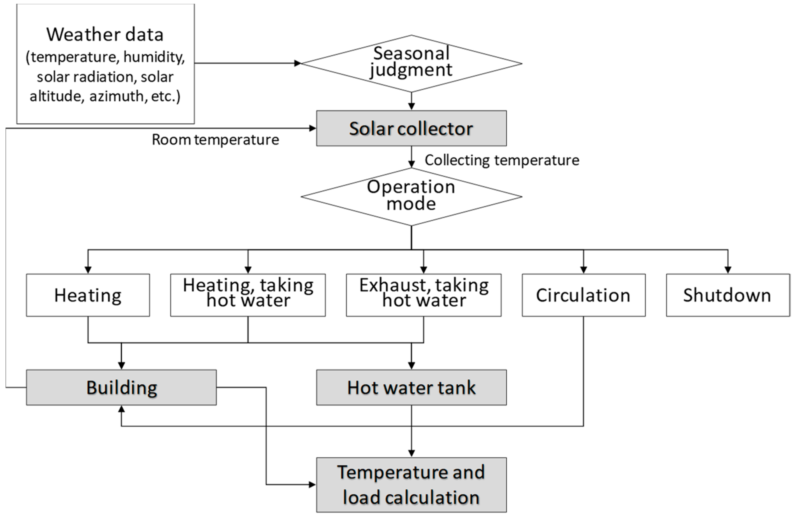
The simulation in this study determines the season first based on the weather data and determines the operation mode based on the collecting air temperature of the solar collector. The operation mode consists of heating, heating after hot water supply, exhaust after hot water supply, indoor circulation, and shutdown. In the case of the hot water supply mode, the collecting air exchanges heat with the hot water tank, and in the heating mode, the collected air enters the underfloor space. Finally, the surface temperature, air temperature, heat flux, and load in the building are calculated. The simulation flow in this study is shown in Figure 1. The Excel-based thermal load analysis (ExTLA) is used as a thermal load simulation in this study [31]. By performing an iterative calculation (up to 32,767 times) in Microsoft Excel, the convergence criterion is met when the change in the value of the calculation result is no greater than the set maximum change value. Divergence is prevented by using the alleviation coefficient. Based on the properties calculated from the upper cells, ExTLA calculates solar-radiation-related items, calculates the node temperature inside the wall, and then calculates the room temperature (including ventilation and latent heat). For the purposes of improving the calculation speed and convenience of use, calculation conditions such as weather conditions and air conditioning settings are input into the “input sheet”, the composition of the building and the characteristics of the members are input into the “setting sheet”, the calculated result of the previous time step is listed on the “T0 sheet”, and the thermal load calculation for the building and equipment is shown on the “T1 sheet”. The items to be calculated can be set as required and can output periodic and daily data for the building and equipment, as required.
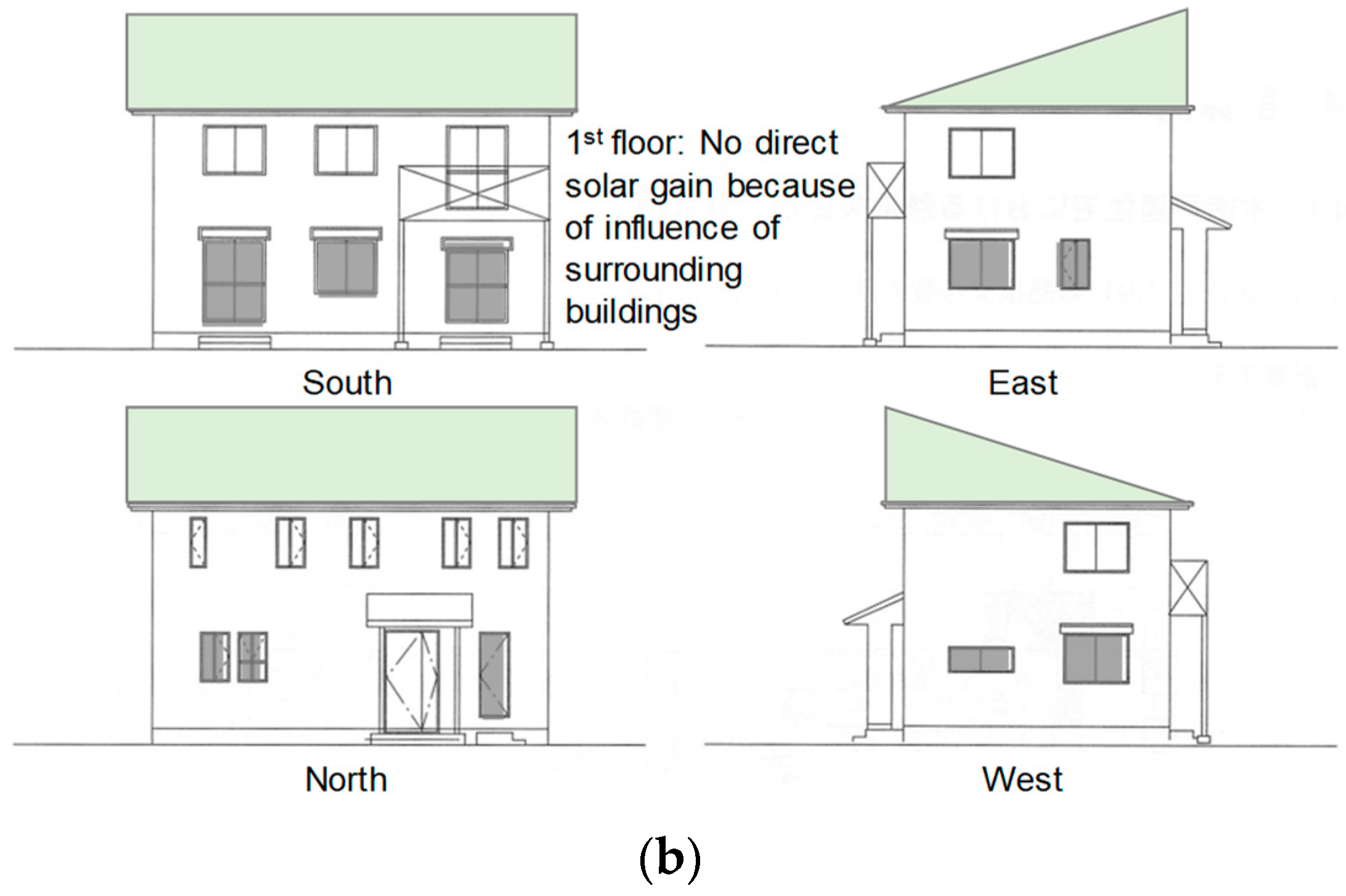
The target building is a Japanese standard house of the Japanese energy saving standard (next-generation energy saving standard) [32]. The solar collector is set based on the latitude of Tokyo (35.4° N). Assuming that there are surrounding buildings, the solar transmittance of the window on the first floor is set to zero. Figure 2 and Table 1 show the building information. In this simulation, a four-person family is targeted, and 450 L per day of hot water consumption is assumed [32]. Table 2, Table 3 and Table 4 present the simulation conditions, indoor heat generation, and hot water supply usage, respectively. The areas of the preliminary collector and glass heat collector are set as 45 m2 and 15 m2, respectively. The hot water storage tank is set to a 1000 L capacity.
3. Simulation Model of Solar Collector
Using the calculation model of the air-based solar heat collector, the temperature of the heat medium of the collector and the heat collection intensity were calculated [33]. Figure 3 shows a conceptual diagram of the collector model. The outlet temperature and heat collection intensity of the collector can be calculated from the inlet temperature, the sol-air temperature, and the coefficient of heat transfer of the collector by Equations (1) and (2). The sol-air temperature corresponding to the collector is obtained from Equation (4) and Table 5. The sol-air temperature on the outside air side (Tcoleu) was calculated by the solar radiation amount and the night radiation of the outside surface of the collector, and the outside air temperature. The sol-air temperature on the indoor side (Tcoled) was set to the room-side surface temperature of the collector. In the case of a preliminary collector, it was calculated by neglecting solar-radiation transmission and the thermal resistance of surface material. The kd and ku in Equation (4) represent the ratio of the thermal transmittance on the indoor side (Kcd) or the outdoor side (Kcu) to the overall thermal transmittance (Kc) of the collector. The thermal transmittance on the outdoor side (Kcu) and the thermal transmittance on the indoor side (Kcd) are determined by the heat resistance of the collector panel and the heat transfer due to the air flow, and the calculation method is expressed in Equations (5)–(8). The coefficient of heat transfer by convection is calculated by the wind speed using the Jurges equation.
Tfout = Tcole − (Tcole − Tfin) exp(−KcAc/cfGf)
Qc = cfGf(Tfout − Tfin) = cfGfεc(Tcole − Tfin)
εc = 1 − exp(−KcAc/cfGf)
Tcole = kuTcoleu + kdTcoled
Kcu = Ksufcu, Kcd = Ksdfcd
fcu = αcWsdb12+ αcWsub22
fcd = αcWsdb11+ αcWsub21
b11= (αr + αc + Ksu)/Det, b12 = αr/Det,
b21 = αr(Wsu/Wsd)/Det, b22 = (αrWsu/Wsd + αc + Ksd)/Det
Det = (αrAsu/Asd + αc + Ksd)(αr + αc + Ksu) − αr2(Asu/Asd)
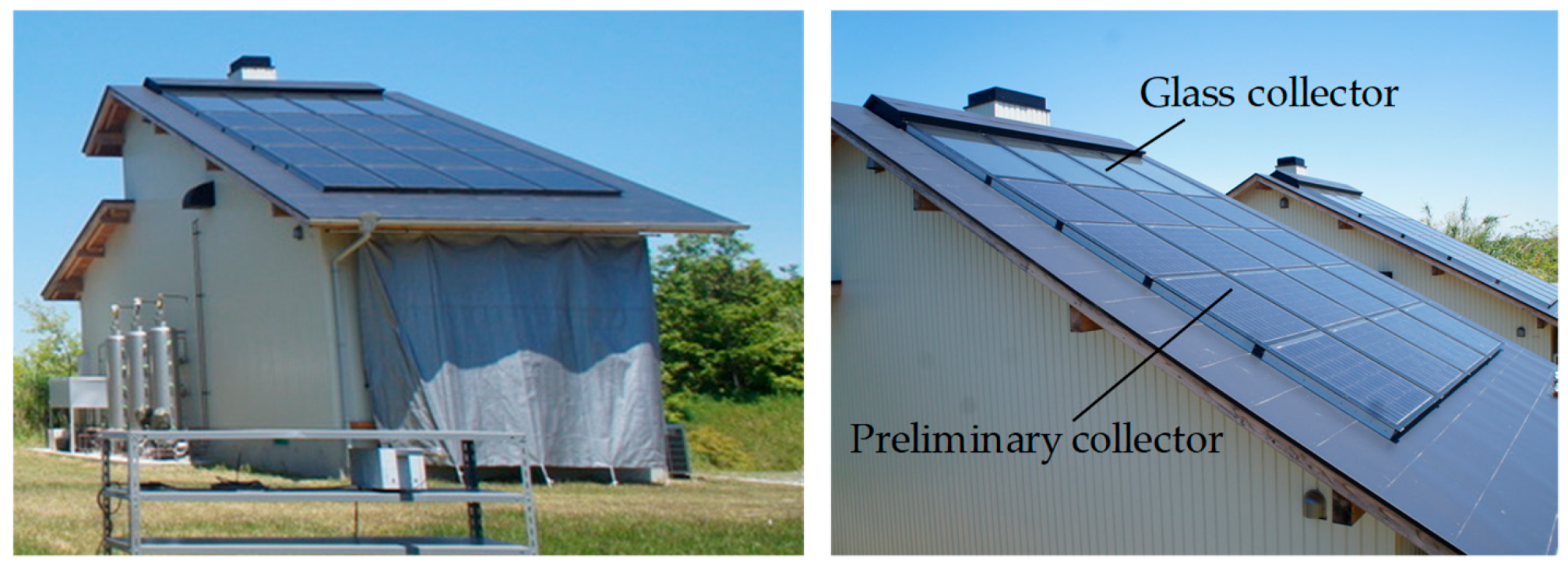
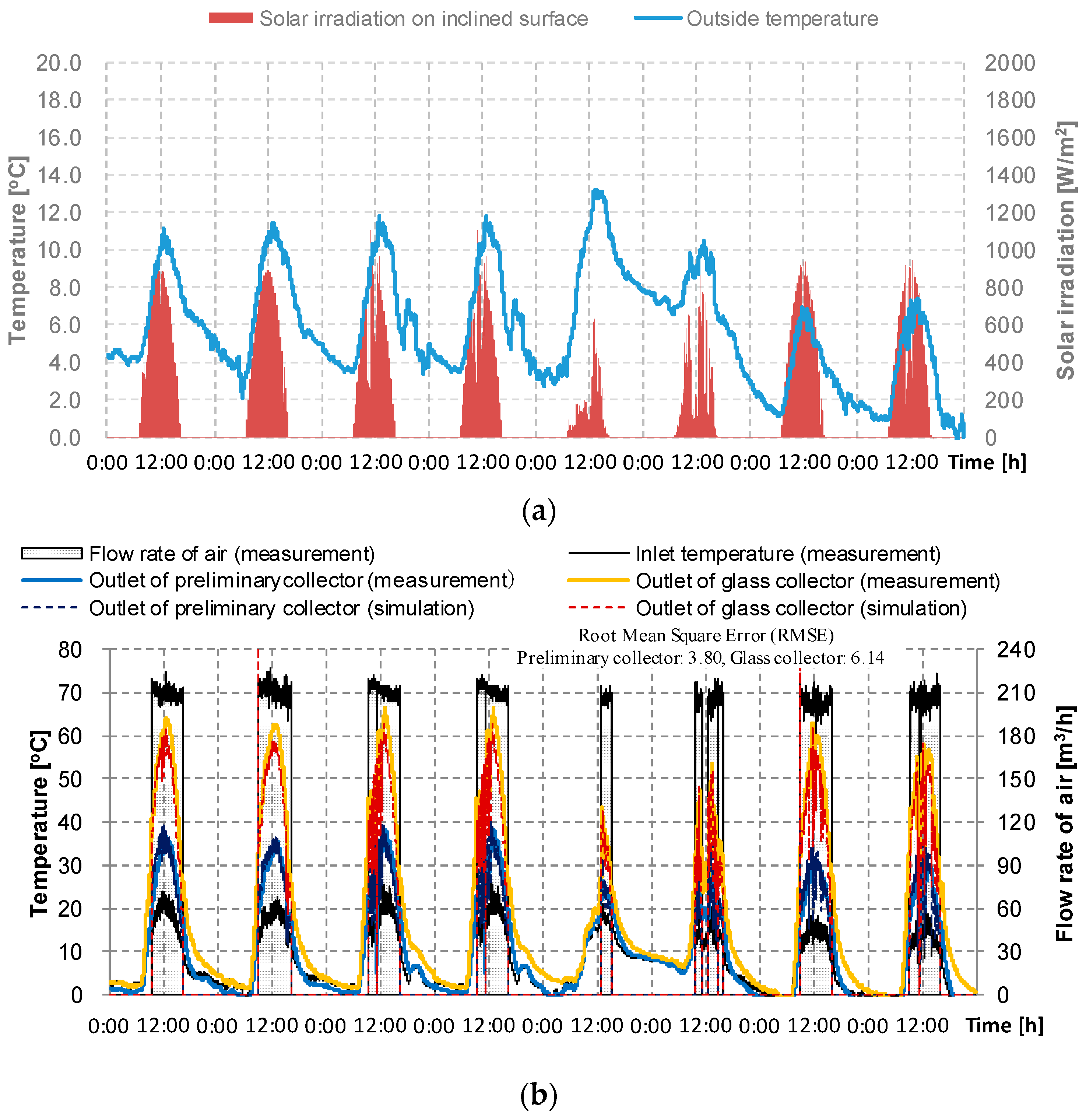
To investigate the accuracy of the calculation model of the air-based solar heat collector, the collector outlet temperatures from the experiment and simulation were compared under the same conditions of outside temperature, inlet temperature, and volume flow rate of air. Figure 4 shows the target collector of the experiment [20]. Table 6 shows the measurement instruments used in this study. Figure 5 shows the results for 8 days (December 23–30, 2013) for a preliminary collector area of 3.45 m2 and a glass collector area of 1.32 m2. It is surmised that the marginal difference between the two outlet temperatures is influenced by both the temperature distribution on the back surface of the collectors and equipment measurement errors. However, in this study into the effect of the presence of the solar heat collector, the accuracy of the simulation is assumed to be sufficient.
4. Performance of the Air-Based Solar Heating System
4.1. Simulation Results for Typical House (Non-Solar Heat Collection)
In order to verify the improvement of the indoor thermal environment and the effect of load reduction according to the application of the air-based solar heating system, a general house without a solar heating system was calculated first. Figure 6, Figure 7 and Figure 8 show the results for 5 days when solar heat was available during January when the ambient temperature was low. Figure 6 shows the ambient temperature and the solar irradiance at the solar collector (south, inclination angle 35.4°) in the target period. As shown in Figure 7, in the case of the first floor where direct gain through the window is not available, the indoor temperature could not reach the heating set temperature (20 °C) during the entire target period. In contrast, in the case of the second floor, the indoor temperature exceeded 20 °C due to the use of solar heat in the daytime, but the room temperature rapidly dropped at night due to lack of thermal storage. Figure 8 shows the hot water supply load during the target period. The hot water supply load was 8612–9167 W at 21:00 when the usage amount of hot water was a maximum, and an average 59.73 MJ per day is required for the hot water supply.
4.2. Simulation Results for the Air-Based Solar Heating System
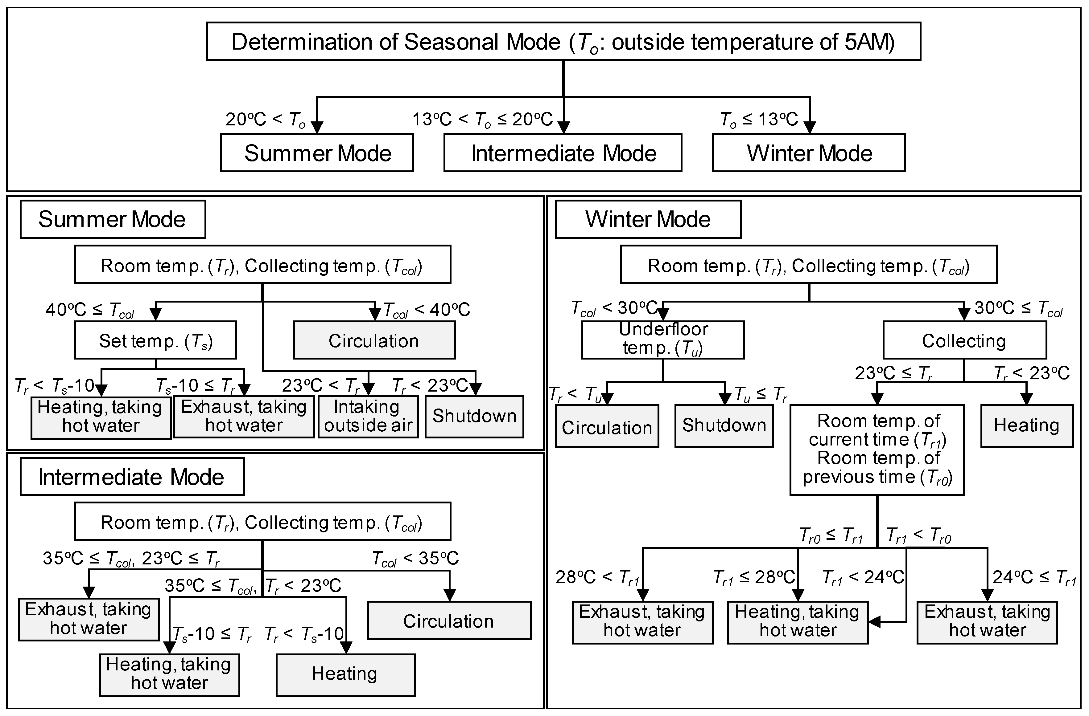
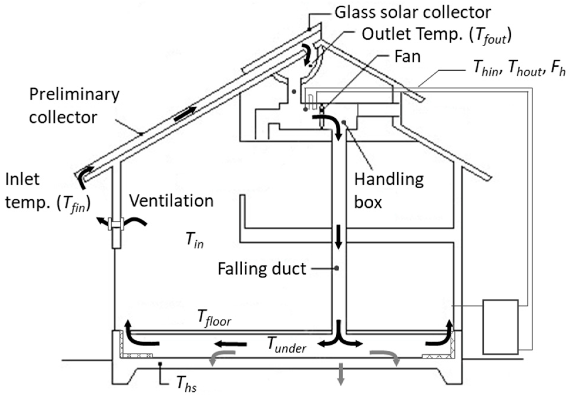
The indoor thermal environment for the application of the air-based solar heating system was calculated. Figure 9 shows the control of the air-based solar heating system used in this study. First, the seasons are determined based on the ambient temperature at 5:00 am, and heating, hot water supply, indoor circulation, and shutdown are judged based on room temperature, the outlet temperature of the collector, the temperature of the underfloor and so on. Figure 10 shows a conceptual diagram of the studied air-based solar heating system.
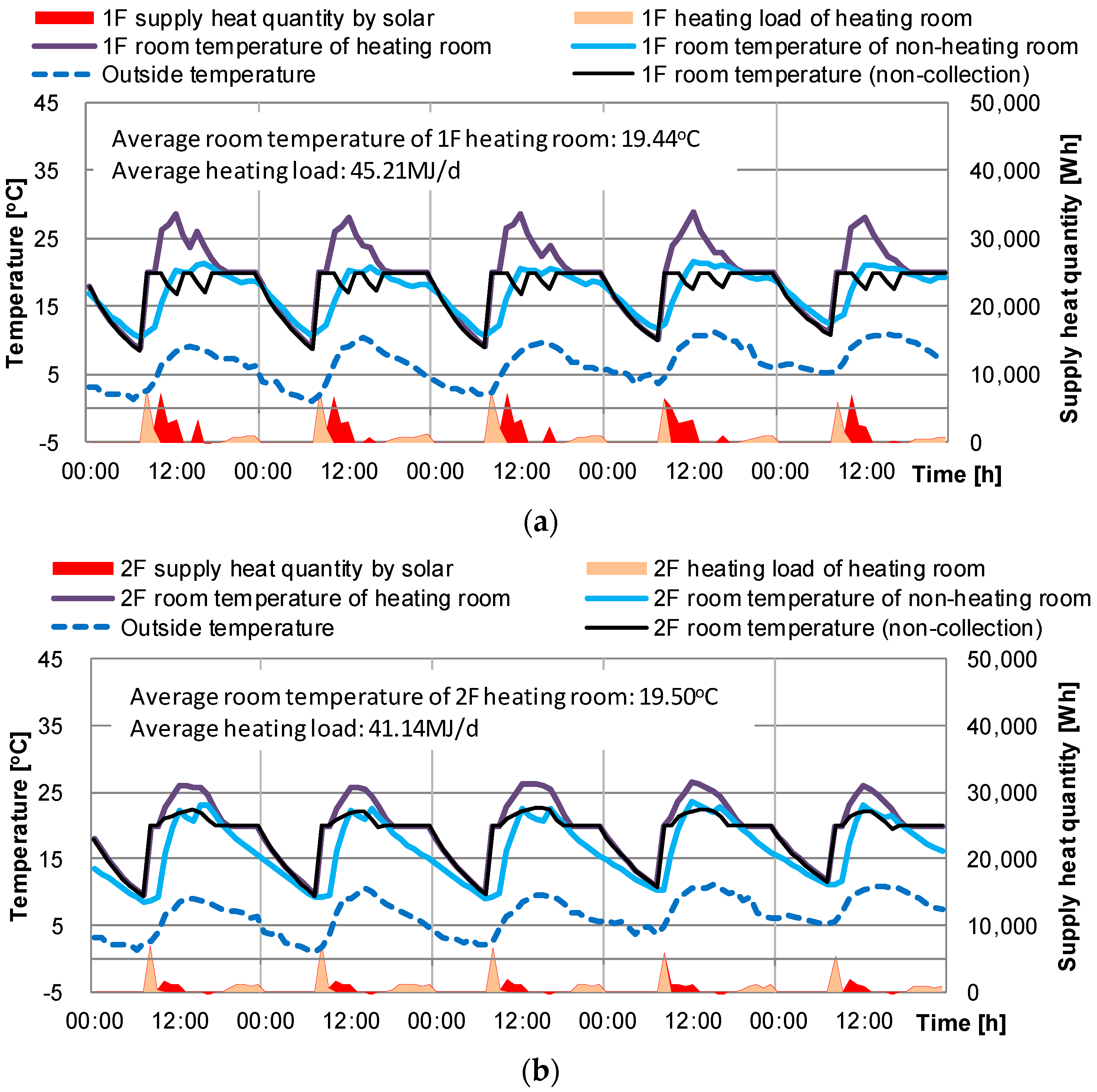
By applying the air-based solar heating system, the room temperature increases because heated air is blown into the room during the day, as shown in Figure 11. In the case of the first-floor heating room, the average room temperature increased from 17.34 °C to 19.44 °C—i.e., by about 2.1 °C—and the heating load was reduced by 42.5% from 78.56 MJ per day to 45.21 MJ per day. In the case of the second-floor heating room, the indoor temperature increased from 18.4 °C to 19.5 °C and the heating load decreased by about 18.6% from 50.51 MJ per day to 41.14 MJ per day. It is considered that the effect of reducing the load on the first floor is larger because the original heat load of the second floor is not large due to the solar radiation, and the heated air first flows into the first floor.
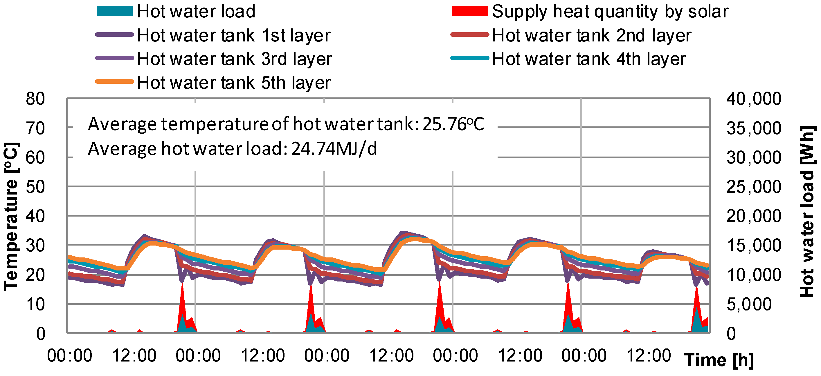
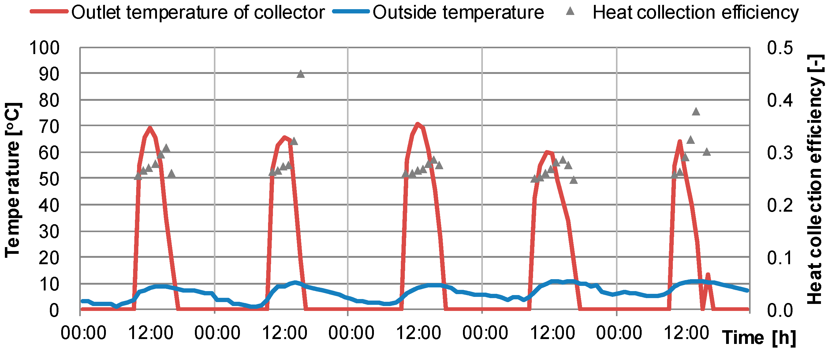
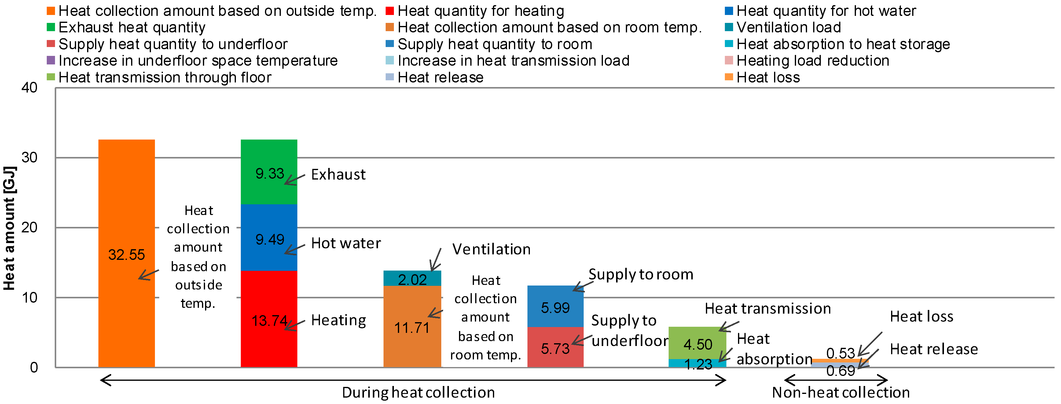
However, due to the influx of the collected air, the room temperature was overheated up to 28.8 °C during the winter daytime. On the other hand, during non-heating at night, the room temperature dropped to a minimum of 8.9 °C. These results indicate the temperature imbalance during solar heat utilization and the necessity of thermal storage. At that time, the temperature inside the hot water storage tank (Figure 12), based on the hot water mode, increased by 16.1 °C to 34.1 °C by heat exchange with solar heat. Figure 13 shows the inlet and the outlet temperatures of the collector and the heat collector efficiency from January 7–11. The air temperature increased up to 71.0 °C by solar heat collection, and the average heat collector efficiency was 28.3%. Figure 14 shows the heat flux from heat collection of the air-based solar system. The heat input to the room by the solar heat collector was 11.71 GJ, but 5.99 GJ was used to raise the indoor room temperature and 5.73 GJ was supplied to the underfloor space. Of the heat supplied to the underfloor space, only 1.23 GJ (about 21.5%) was used as thermal storage, and 0.53 GJ of this was heat loss.
As shown in Table 7, by using the air-based solar heating system, the annual indoor heating load was reduced by 5.39 GJ and the annual hot water load reduced by 10.32 GJ in the target building of this study. As a result, the annual load is reduced by about 48.3% by using the air-based solar heating system.
Figure 15 shows the flow of heat collected by the air-based solar heat collecting system. The heat collection amount can be calculated based on the outside air temperature, the collector outlet temperature, to which the temperature increased because of heat collection, and the flow rate of air at the time of heat collection. Heat exchange caused by heat collection is performed for hot water in the handling box, and the internal temperature of the hot water storage tank is increased. The air in the handling box is exhausted outdoors after exchanging heat with the hot water supply when it is used for heating by blowing into the living room through the underfloor space, depending on the room temperature condition or when the room temperature is high. However, because the amount of heat entering the room for heating use is a calorific value based on the outside air temperature, it is divided into a ventilation load and a room temperature standard heat collection amount when entering the room. The room-temperature-based heat collection amount includes the amount of heat transferred directly to the living room space by convection during heat collection, the temperature increase in the underfloor space, the amount of heat absorption to the heat storage body (such as foundation concrete and additional heat storage), and the amount from the underfloor space to the living room (such as the amount of heat flowing through the floor). After heat collection stops, the heat absorbed by the regenerator generates heat loss to the outside air and the ground, and the remaining heat dissipates to the underfloor space. The calculation of each element is shown in Equations (9)–(18).
Qout = (Tfout − Tfin)VccpaT(h)
Qhw = (Thout − Thin)FhcpmT(h)
Qht = (Tduct − Tfin)VccpaT(h)
Qin = (Tduct − Tin)VccpaT(h)
Qv = (Tin − Tfin)VccpaT(h)
Qr = (Tunder − Tin)VccpaT(h)
Qunder = (Tduct − Tunder)VccpaT(h)
Qf = (Tfloor − Tin)αcAfloorT(h)
Qab = (Tunder − Ths)αcAhsT(h)
Qra = (Ths − Tunder)αcAhsT(h)
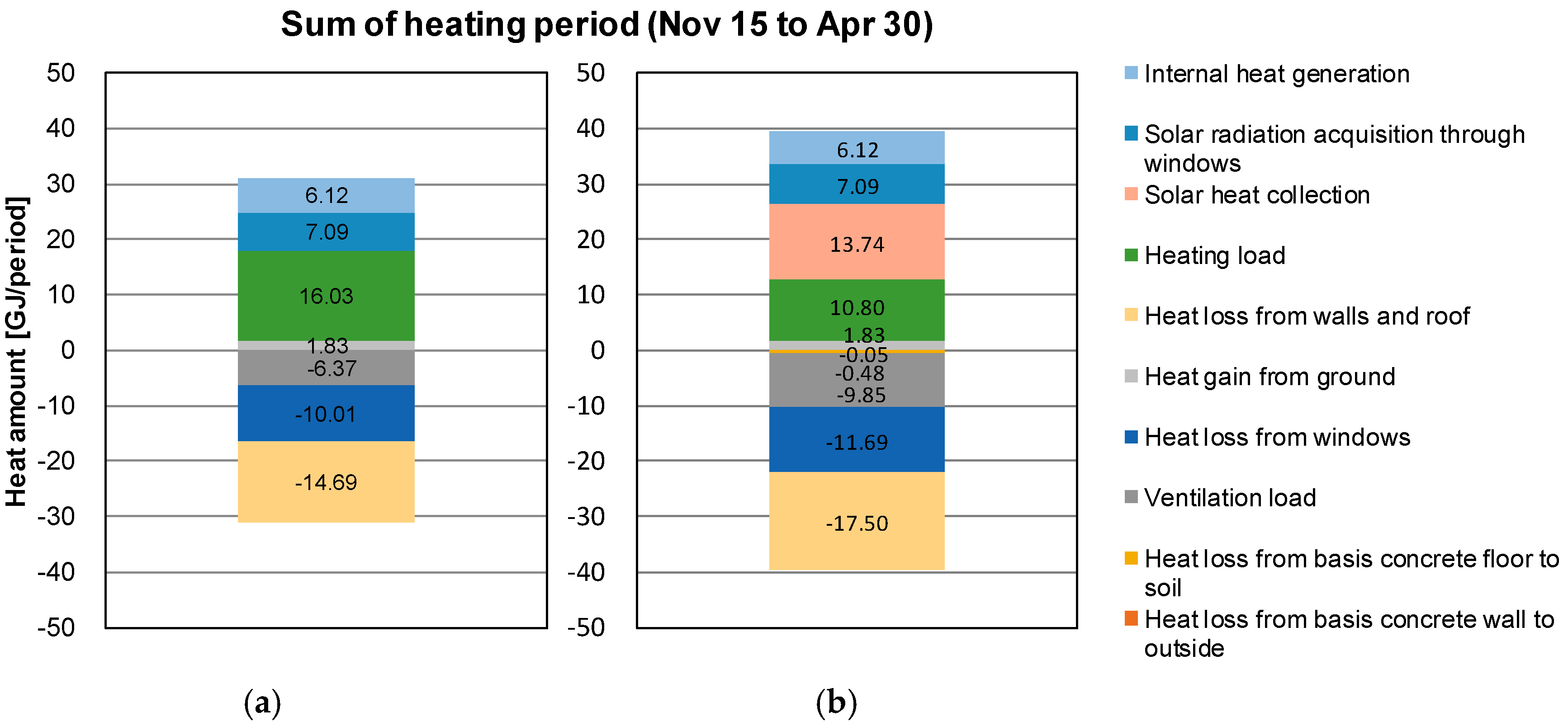
Figure 16 shows the thermal balance of the energy supplied to the room and the heat loss to the outside in the winter. During this period, the amount of indoor heat supplied by heat collection rises to 13.74 GJ; however, as the room temperature increases, the heat losses from the wall, the roof, the window, and the room ventilation load increase. Results indicate that the heating load is reduced by 5.23 GJ by the air-based solar heating system. We confirmed that the room temperature of the first floor reached a maximum of 20 °C or greater. This result indicates that the solar heat collection causes daytime overheating. To increase the annual load reduction effect of the air-based solar heating system, it is necessary to not only increase the amount of solar heat collection, but also to solve the problems of heat loss because of overheating in the daytime and room temperature decreasing at night using thermal storage. In addition, it is necessary to study the control of the system that balances the reduction of exhaust heat and the utilization of solar heat for heating and hot water supply. Although it is possible to increase the heat collection amount by increasing the heat collection area, it is essential to increase the heat collection performance of the heat collector for use on a limited roof area. To increase the heat storage performance, insulation can be installed to reduce heat loss from the heat storage body to the outside, stored heat can be radiated into the indoor space, the heat capacity of the heat storage can be increased, and the heat flow rate can be increased via increases in wind speed and surface area. In the system operation control, suitable control varies depending on the balance between the heating load and hot water supply load based on the weather conditions, building performance, and hot water supply usage amount of the installation area. For example, in a case in which the heating load is small but the hot water supply load is large, it is possible to increase the annual load reduction amount by the preferential use of the collected heat for hot water supply.
5. Conclusions
In this study, a roof-integrated air-based solar collection system is proposed. The proposed system is used for heating or hot water depending on the seasonal and indoor temperature conditions. Especially in Japan, where convective heating is dominant, the system is considered to be highly utilized. In this study, an annual thermal simulation was conducted to determine the performance of an air-based solar heat collecting system. The system was developed based on previous studies into solar thermal system simulation models. The accuracy of the simulation model was evaluated by comparison with experimental results, and the validity of the simulation was confirmed.
To analyze the effect of the air-based solar heating system proposed in this study, the indoor temperature, heating load, and hot water load of a typical house with no solar heating system and a house with the proposed system were calculated. The annual heating load was reduced by 5.39 GJ and the hot water load was reduced by 10.32 GJ when using the air-based solar heating system, which was a 48.3% annual load reduction. In addition, by confirming the heat balance based on solar heat collection, the possibility of improving the performance of the existing system was shown. In the future, we will propose system improvements by investigating changes to the collector, control, and insulation, and with the addition of thermal storage.
Author Contributions
Conceptualization, Y.C. and W.C.; Methodology, M.M.; Software, Y.C.; Validation, Y.C., M.M. and H.R.; Formal Analysis, Y.C.; Investigation, Y.C.; Resources, H.R.; Data Curation, H.R.; Writing-Original Draft Preparation, Y.C.; Writing-Review & Editing, W.C.; Visualization, Y.C.; Supervision, M.M.; Project Administration, M.M.
Funding
This research received no external funding
Conflicts of Interest
The authors declare no conflict of interest.
Nomenclature
| Ac | Collector area [m2] |
| Afloor | Surface area of room floor [m2] |
| Ahs | Surface area of heat storage [m2] |
| Asd, Asu | Area of collector frontside and backside, respectively [m2] |
| asu | Absorption rate of solar collector [-] |
| cf | Specific heat of air static pressure [J kg−1 K−1] |
| cpa | Volume-specific heat of air [J m−3 K−1] |
| cpm | Specific heat of heating medium [J kg−1 K−1] |
| Fh | Mass flow rate of heating medium in handling box [kg s−1] |
| Gf | Mass flow rate of air [kg s−1] |
| I | Solar irradiation on inclined surface [W m−2] |
| Kc | Overall coefficient of heat transfer of collector [W m−2 K−1] |
| Kcu | Overall coefficient of heat transfer on the outdoor side [W m−2 K−1] |
| Kcd | Overall coefficient of heat transfer on the indoor side [W m−2 K−1] |
| kd | Ratio of the heat transmittance on the indoor side [-] |
| ku | Ratio of the heat transmittance on the outdoor side [-] |
| Qab | Heat absorption to heat storage [Wh] |
| Qc | Heat collection intensity [Wh] |
| Qf | Heat transmission [Wh] |
| Qht | Heat amount to heating [Wh] |
| Qhw | Heat amount to hot water supply [Wh] |
| Qin | Heat collection amount referenced to room temperature [Wh] |
| Qout | Heat collection amount referenced to outside temperature [Wh] |
| Qr | Heat supply to room [Wh] |
| Qra | Heat radiation from heat storage [Wh] |
| T(h) | Time period [h] |
| Qunder | Heat supply to underfloor space [W] |
| Qv | Ventilation load [W] |
| ra | Thermal resistance of hollow layer [m2 K W−1] |
| rb | Thermal resistance of surface material [m2 K W−1] |
| Rskyc | Longwave radiation to sky [W m−2] |
| Tcole | Sol-air temperature of collector [°C] |
| Tcoled | Sol-air temperature on the indoor side [°C] |
| Tcoleu | Sol-air temperature on the outside air side [°C] |
| Tduct | Outlet temperature of air in handling box [°C] |
| Tfin | Collector inlet temperature, outside temperature [°C] |
| Tfloor | Surface temperature of room floor [°C] |
| Tfout | Collector outlet temperature [°C] |
| Tfin | Collector inlet temperature [°C] |
| Thin | Inlet temperature of heating medium in handling box [°C] |
| Thout | Outlet temperature of heating medium in handling box [°C] |
| Ths | Surface temperature of thermal storage [°C] |
| To | Outside temperature [°C] |
| Tunder | Underfloor space temperature [°C] |
| Tx | Collector backside temperature [°C] |
| Vc | Volume flow rate of air in collection [m3 s−1] |
| Wsd, Wsu | Width of collector frontside and backside, respectively [m] |
| αc | Coefficient of heat transfer by convection [W m−2 K−1] |
| αo | Overall coefficient of heat transfer [W m−2 K−1] |
| αr | Coefficient of heat transfer by radiation [W m−2 K−1] |
| εc | Thermal efficiency of heat exchanger in collector [-] |
| τg | Solar transmittance of glazing [-] |
References
- Kannan, N.; Vakeesan, D. Solar energy for future world:—A review. Renew. Sustain. Energy Rev. 2016, 62, 1092–1105. [Google Scholar] [CrossRef]
- Bliss, R.W. The derivations of several plate efficiency factors useful in the design of flat—Plate solar heat collectors. Sol. Energy 1959, 3, 55–61. [Google Scholar] [CrossRef]
- Hill, J.E.; Streed, E.R. A method of testing for rating solar collectors based on thermal performance. Sol. Energy 1976, 18, 421–429. [Google Scholar] [CrossRef]
- Dorfling, C.; Hornung, C.H.; Hallmark, B.; Beaumont, R.J.J.; Fovargue, H.; Mackley, M.R. The experimental response and modelling of a solar heat collector fabricated from plastic microcapillary films. Sol. Energy Mater. Sol. Cells 2010, 94, 1207–1221. [Google Scholar] [CrossRef]
- Wei, L.; Yuan, D.; Tang, D.; Wu, B. A study on a flat-plate type of solar heat collector with an integrated heat pipe. Sol. Energy 2013, 97, 19–25. [Google Scholar] [CrossRef]
- Hussein, H.M.S.; Mohamad, M.A.; El-Asfouri, A.S. Optimization of a wickless heat pipe flat plate solar collector. Energy Convers. Manag. 1999, 40, 1949–1961. [Google Scholar] [CrossRef]
- Alvarez, A.; Cabeza, O.; Muñiz, M.C.; Varela, L.M. Experimental and numerical investigation of a flat-plate solar collector. Energy 2010, 35, 3707–3716. [Google Scholar] [CrossRef]
- Huang, B.J.; Lin, T.H.; Hung, W.C.; Sun, F.S. Performance evaluation of solar photovoltaic/thermal systems. Sol. Energy 2001, 70, 443–448. [Google Scholar] [CrossRef]
- He, W.; Chow, T.T.; Ji, J.; Lu, J.; Pei, G.; Chan, L.S. Hybrid photovoltaic and thermal solar-collector designed for natural circulation of water. Appl. Energy 2006, 83, 199–210. [Google Scholar] [CrossRef]
- Coventry, J.S. Performance of a concentrating photovoltaic/thermal solar collector. Sol. Energy 2005, 78, 211–222. [Google Scholar] [CrossRef]
- Ji, J.; Lu, J.P.; Chow, T.T.; He, W.; Pei, G. A sensitivity study of a hybrid photovoltaic/thermal water-heating system with natural circulation. Appl. Energy 2007, 84, 222–237. [Google Scholar] [CrossRef]
- Bergene, T.; Løvvik, O.M. Model calculations on a flat-plate solar heat collector with integrated solar cells. Sol. Energy 1995, 55, 453–462. [Google Scholar] [CrossRef]
- Zondag, H.A.; De Vries, D.W.; Van Helden, W.G.J.; Van Zolingen, R.J.C.; Van Steenhoven, A.A. The thermal and electrical yield of a PV-thermal collector. Sol. Energy 2002, 72, 113–128. [Google Scholar] [CrossRef] [Green Version]
- Ibrahim, A.; Othman, M.Y.; Ruslan, M.H.; Mat, S.; Sopian, K. Recent advances in flat plate photovoltaic/thermal (PV/T) solar collectors. Renew. Sustain. Energy Rev. 2011, 15, 352–365. [Google Scholar] [CrossRef]
- Chow, T.T. A review on photovoltaic/thermal hybrid solar technology. Appl. Energy 2010, 87, 365–379. [Google Scholar] [CrossRef]
- Zondag, H.A. Flat-plate PV-Thermal collectors and systems: A review. Renew. Sustain. Energy Rev. 2008, 12, 891–959. [Google Scholar] [CrossRef] [Green Version]
- Riffat, S.B.; Cuce, E. A review on hybrid photovoltaic/thermal collectors and systems. Int. J. Low-Carbon Technol. 2011, 6, 212–241. [Google Scholar] [CrossRef] [Green Version]
- Aste, N.; del Pero, C.; Leonforte, F. Water flat plate PV-thermal collectors: A review. Sol. Energy 2014, 102, 98–115. [Google Scholar] [CrossRef]
- Amori, K.E.; Taqi Al-Najjar, H.M. Analysis of thermal and electrical performance of a hybrid (PV/T) air based solar collector for Iraq. Appl. Energy 2012, 98, 384–395. [Google Scholar] [CrossRef]
- Choi, Y.; Takase, K.; Mae, M. System performance of a residential building using the air-based solar heating system. Sol. Energy 2018, 171, 47–63. [Google Scholar] [CrossRef]
- Sarhaddi, F.; Farahat, S.; Ajam, H.; Behzadmehr, A.; Mahdavi Adeli, M. An improved thermal and electrical model for a solar photovoltaic thermal (PV/T) air collector. Appl. Energy 2010, 87, 2328–2339. [Google Scholar] [CrossRef]
- Amori, K.E.; Abd-AlRaheem, M.A. Field study of various air based photovoltaic/thermal hybrid solar collectors. Renew. Energy 2014, 63, 402–414. [Google Scholar] [CrossRef]
- Othman, M.Y.H.; Sopian, K.; Yatim, B.; Daud, W.R.W. Development of advanced solar assisted drying systems. Renew. Energy 2006, 31, 703–709. [Google Scholar] [CrossRef]
- Zhang, X.; Zhao, X.; Smith, S.; Xu, J.; Yu, X. Review of R&D progress and practical application of the solar photovoltaic/thermal (PV/T) technologies. Renew. Sustain. Energy Rev. 2012, 16, 599–617. [Google Scholar] [CrossRef]
- Arkar, C.; Šuklje, T.; Vidrih, B.; Medved, S. Performance analysis of a solar air heating system with latent heat storage in a lightweight building. Appl. Therm. Eng. 2016, 95, 281–287. [Google Scholar] [CrossRef]
- Kumar, A.; Kim, M.H. Solar air-heating system with packed-bed energy-storage systems. Renew. Sustain. Energy Rev. 2017, 72, 215–227. [Google Scholar] [CrossRef]
- Zhao, D.; Ji, J.; Yu, H.; Wei, W.; Zheng, H. Numerical and experimental study of a combined solar Chinese kang and solar air heating system based on Qinghai demonstration building. Energy Build. 2017, 143, 61–70. [Google Scholar] [CrossRef]
- Wang, Z.Y.; Diao, Y.H.; Liang, L.; Zhao, Y.H.; Zhu, T.T.; Bai, F.W. Experimental study on an integrated collector storage solar air heater based on flat micro-heat pipe arrays. Energy Build. 2017, 152, 615–628. [Google Scholar] [CrossRef]
- Wang, Z.; Diao, Y.; Zhao, Y.; Wang, T.; Liang, L.; Chi, Y. Experimental investigation of an integrated collector–storage solar air heater based on the lap joint-type flat micro-heat pipe arrays. Energy 2018, 160, 924–939. [Google Scholar] [CrossRef]
- Hu, M.; Zhao, B.; Ao, X.; Su, Y.; Pei, G. Parametric analysis and annual performance evaluation of an air-based integrated solar heating and radiative cooling collector. Energy 2018, 165, 811–824. [Google Scholar] [CrossRef]
- Youngjin, C. Performance Improvements of the Air-Based Solar Heating System (Improvement Method of Thermal Performance). E3S Web Conf. 2018, 64, 02004. [Google Scholar] [CrossRef]
- Institute for Building Environment and Energy Conservation. Design Guidelines for Low Energy Housing with Validated Effectiveness; IBEC: Tokyo, Japan, 2010. [Google Scholar]
- Udagawa, M.; Satoh, M.; Roh, H.; Higuchi, Y.; Kusunoki, T. Simulation Models of Building Envelopes for Active Solar Energy Use. In Proceedings of the JSES/JWEA Joint Conference, Chino, Japan, 2009; pp. 107–110. [Google Scholar]
Figure 1.
Simulation flow chart.

Figure 2.
Target building (units: mm). (a) plan; (b) elevation. Reproduced from [32], publisher: 2010.
Figure 2.
Target building (units: mm). (a) plan; (b) elevation. Reproduced from [32], publisher: 2010.
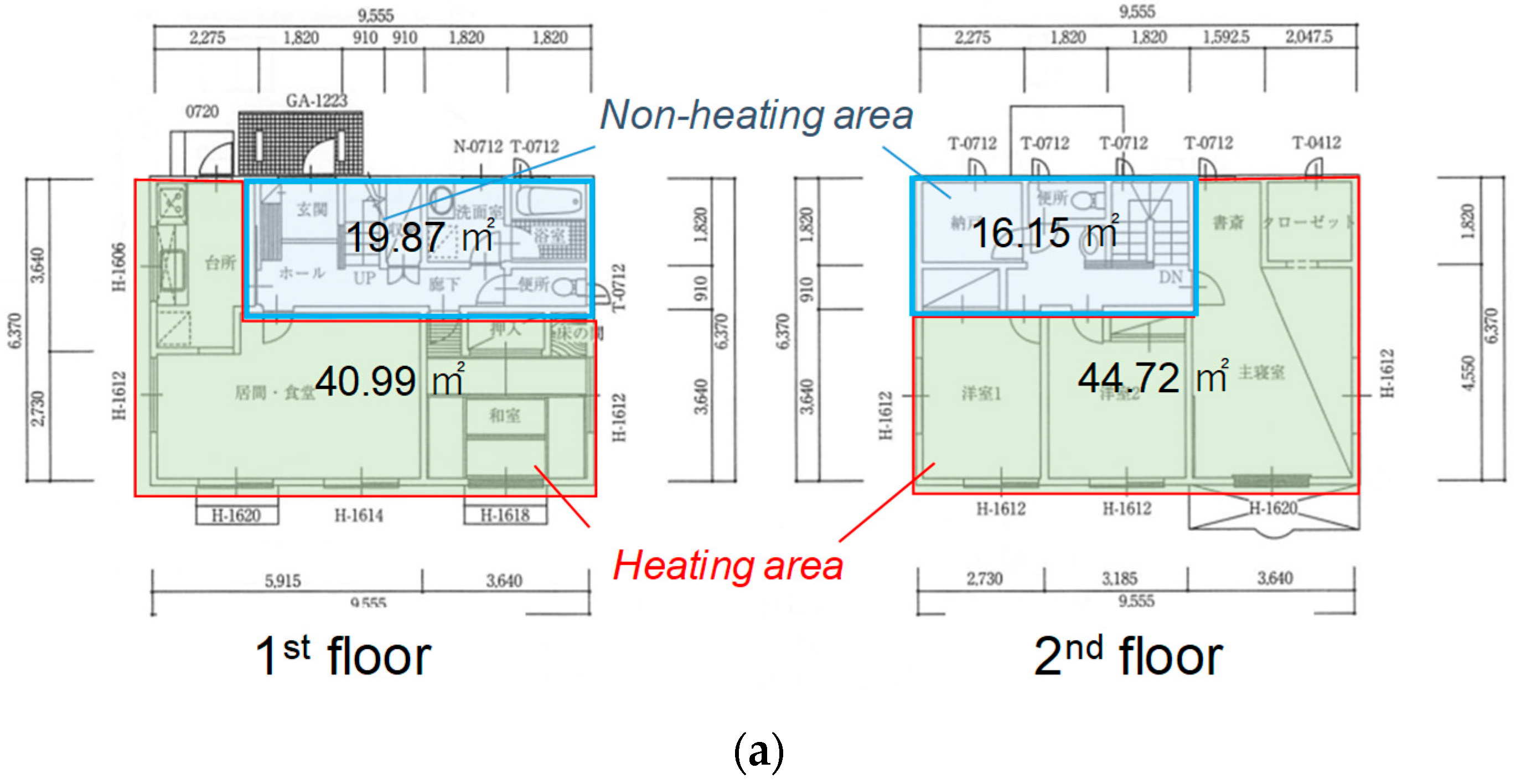

Figure 3.
Air-based solar heat collector model: (a) preliminary collector; (b) glass collector. Reproduced from [33], publisher: 2019.
Figure 3.
Air-based solar heat collector model: (a) preliminary collector; (b) glass collector. Reproduced from [33], publisher: 2019.
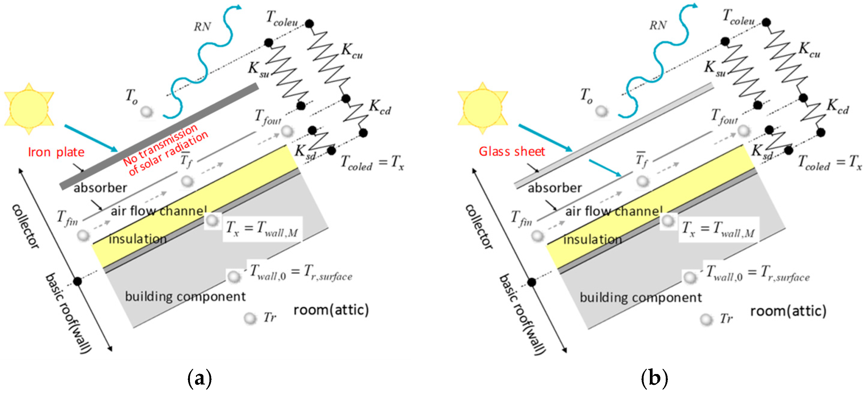
Figure 4.
Target collector. Reproduced from [20], publisher: 2018.
Figure 4.
Target collector. Reproduced from [20], publisher: 2018.

Figure 5.
Accuracy of air-based solar collector model (December 23–30, 2013). (a) weather data; (b) temperature and flow rate.
Figure 5.
Accuracy of air-based solar collector model (December 23–30, 2013). (a) weather data; (b) temperature and flow rate.

Figure 6.
Weather conditions (January 7–11).
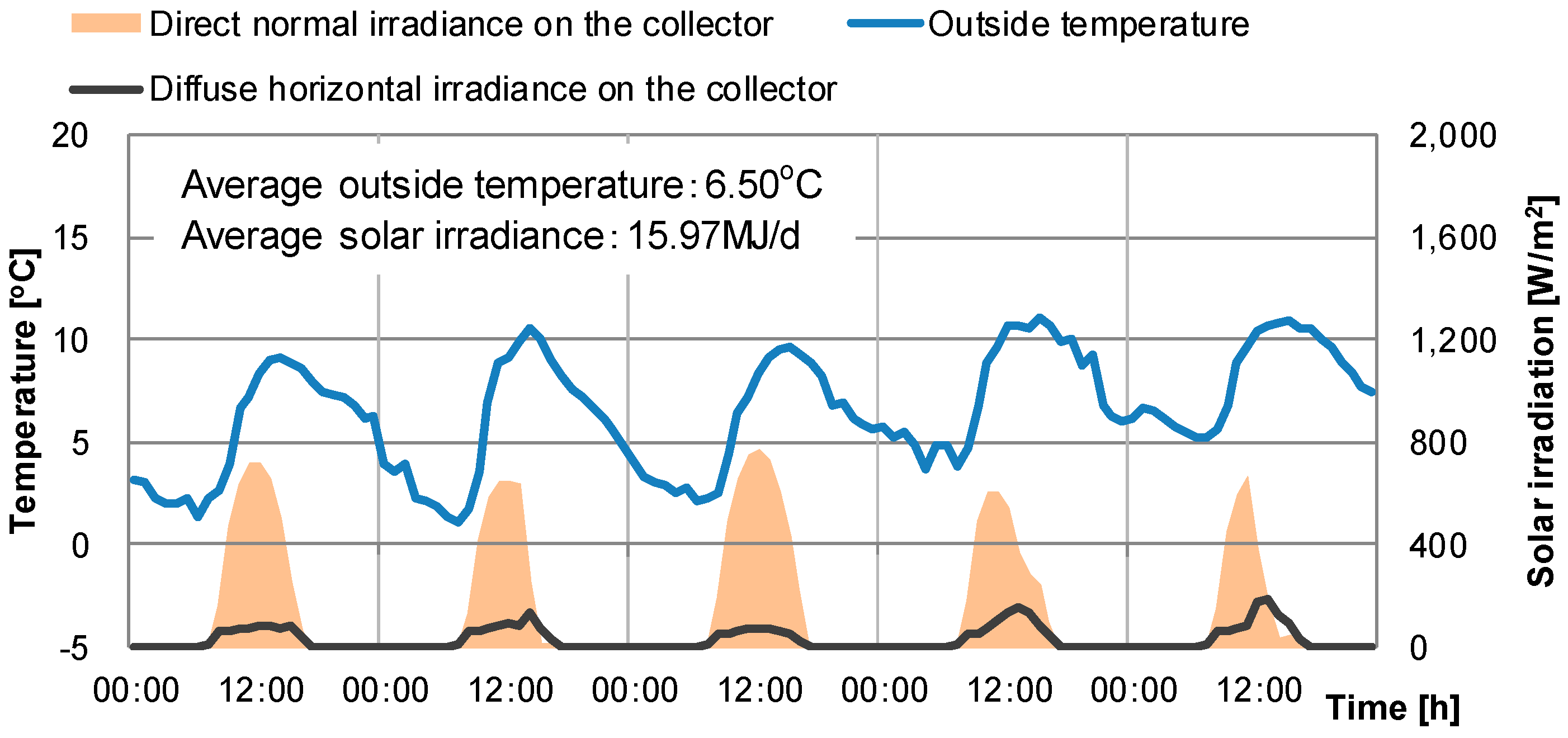
Figure 7.
Room temperature results of a typical house. (a) First floor; (b) Second floor.
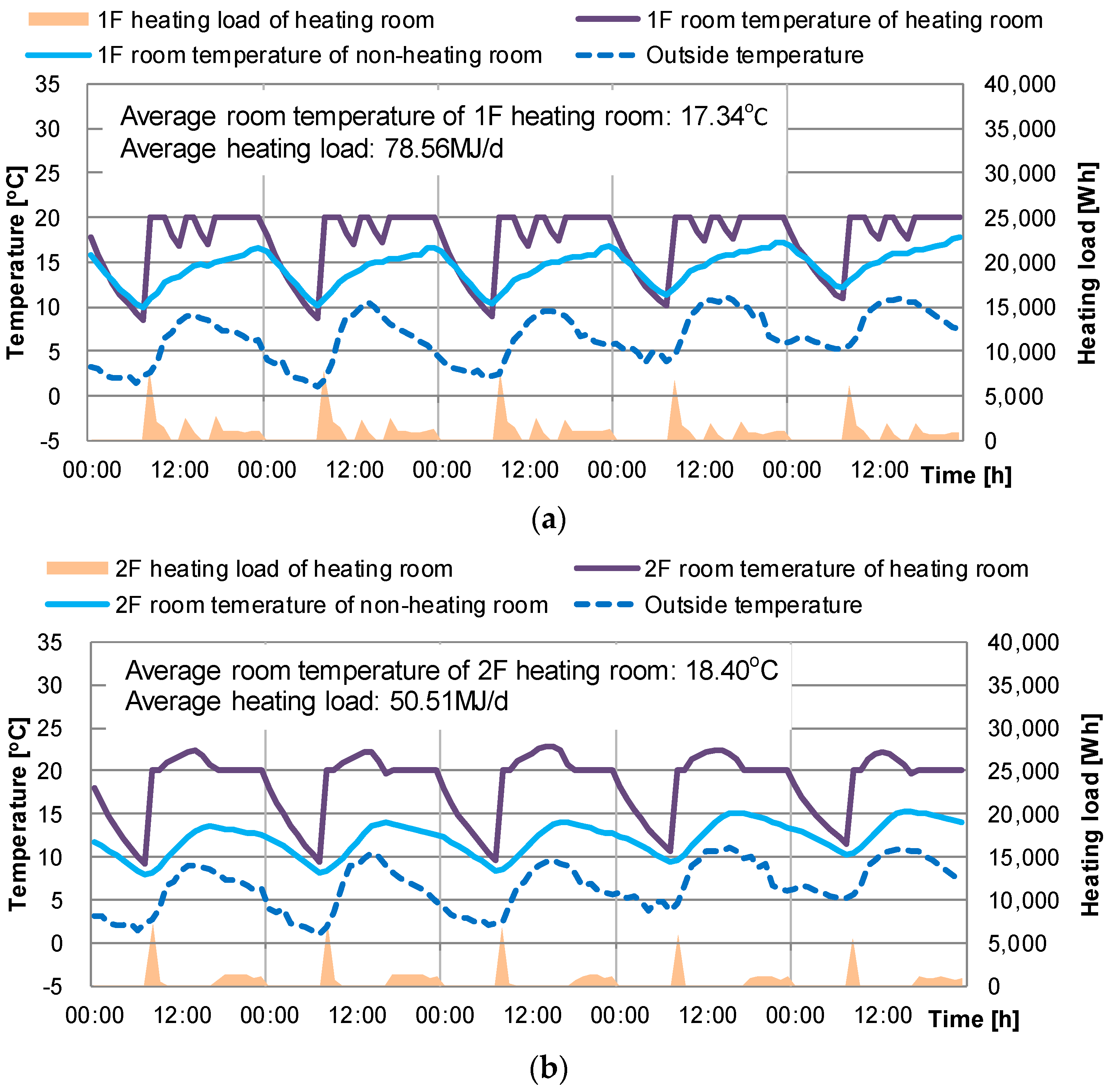
Figure 8.
Hot water supply load of a typical house.
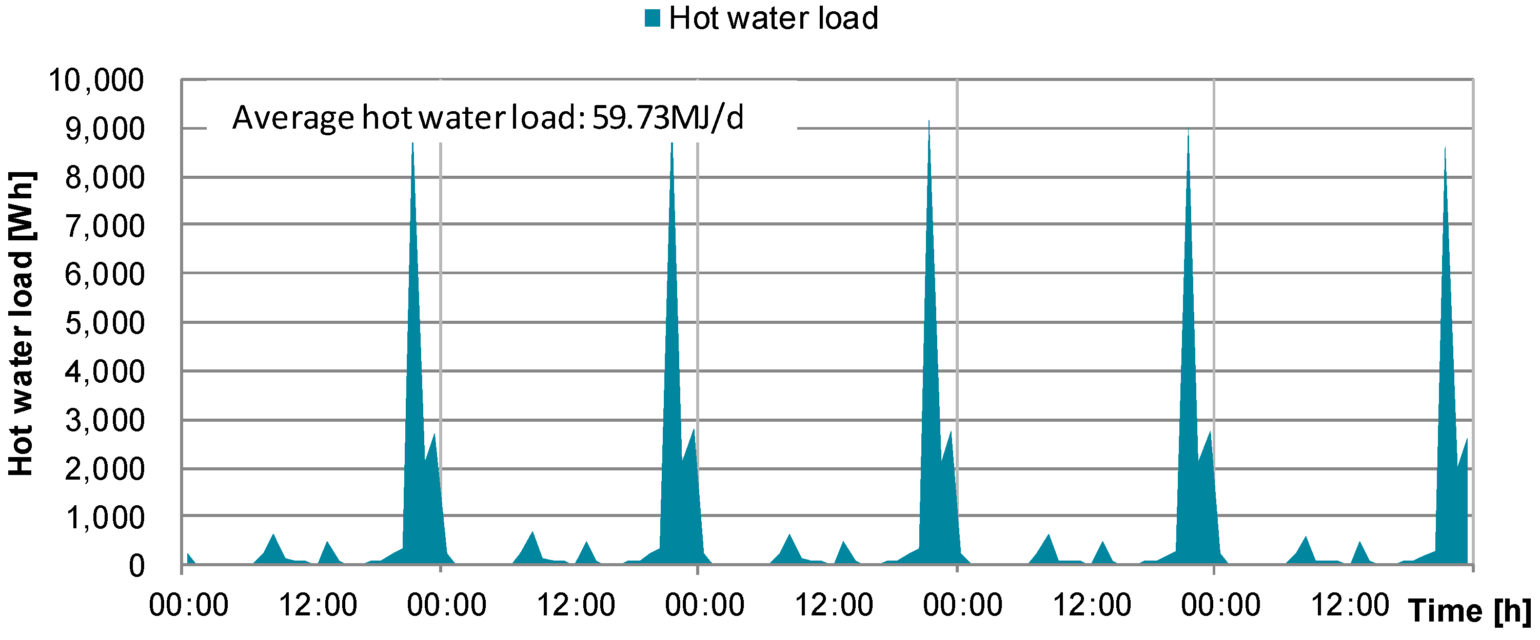
Figure 9.
Operation control of air-based solar heat collection system.

Figure 10.
Conceptual diagram of the air-based solar heat collecting system.
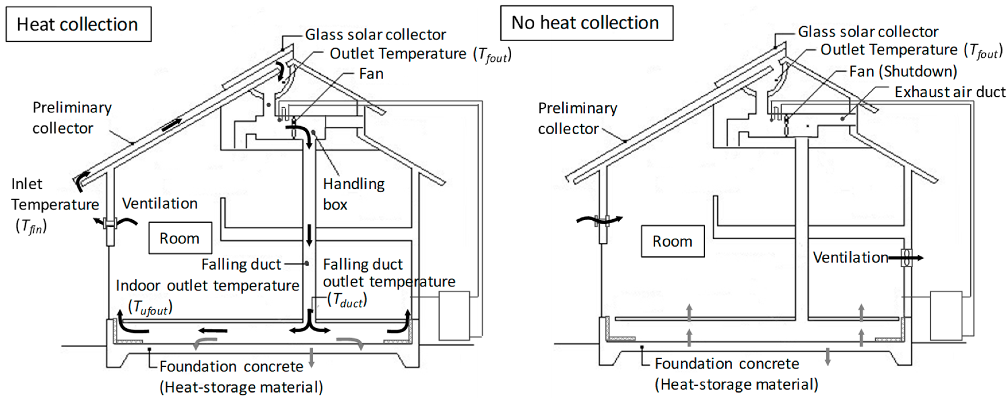
Figure 11.
Room temperatures of the air-based solar system. (a) First floor; (b) Second floor.

Figure 12.
Temperature inside the hot water storage tank of the air-based solar system.

Figure 13.
Outlet temperature of the collector and heat collector efficiency of the air-based solar system.
Figure 13.
Outlet temperature of the collector and heat collector efficiency of the air-based solar system.

Figure 14.
Heat flow from the heat collection of the air-based solar system.

Figure 15.
Conceptual diagram of the heat balance calculation.

Figure 16.
Heat balance of heat supply and heat loss in winter: (a) typical house (non-heat collection); (b) house with an air-based solar system.
Figure 16.
Heat balance of heat supply and heat loss in winter: (a) typical house (non-heat collection); (b) house with an air-based solar system.

Table 1.
Specification of target building.
| Area | Total floor area: 121.73 m2 Heating area of 1st floor: 40.99 m2, Non-heating area of 1st floor: 19.87 m2 Heating area of 2nd floor: 44.72 m2, Non-heating area of 2nd floor: 16.15 m2 |
| Volume | 328.06 m3 (including underfloor space) |
| Insulation of each part | Ceiling: glasswool 18 kg m−3, t = 210 mm Wall: glasswool 16 kg m−3, t = 100 mm Roof: glasswool 32 kg m−3, t = 50 mm Basis concrete: extruded polystyrene foam, t = 50 mm |
| Window | Plain double-glazed glass (Uw: 4.65 W m−2 K−1) |
| Overall heat transfer coefficient (UA-value) | 0.83 W m−2 K−1 |
| Overall coefficient of heat transfer of hot water tank | 0.70 W m−2 K−1 (insulation: 50 mm, thermal conductivity: 0.036 W m−1 K−1) |
Table 2.
Simulation conditions.
| Weather data | Expanded AMeDAS (Automated Meteorological Data Acquisition System) data standard (2000) Tokyo |
| Heating setpoint | 20 °C |
| Heating schedule | 07:00 to 10:00, 12:00 to 14:00, 16:00 to 23:00 |
| Inclination angle of collector | Latitude of Tokyo (35.4° N) |
| Calculation | Preliminary calculation: from January 1 to April 30, Target period: May 1 to April 30 of following year |
| Time step | 1 h |
| Usage of hot water | 450 L per day (40 °C for using hot water) |
| Internal heat gain | 13.26 kWh per day |
| Collector area Flow rate of air | Preliminary collector: 45 m2, glass collector: 15 m2 Volume flow rate of air: 780 m3 h−1 |
Table 3.
Internal heat gains for simulation.
| Equipment [W] | Occupants [W] 60 W Per Person | Lighting [W] | ||||||||||
|---|---|---|---|---|---|---|---|---|---|---|---|---|
| 1F Heating | 1F Non-Heating | 2F Heating | 2F Non-Heating | 1F Heating | 1F Non-Heating | 2F Heating | 2F Non-Heating | 1F Heating | 1F Non-Heating | 2F Heating | 2F Non-Heating | |
| 1:00 | 66.9 | 41.5 | 18.0 | - | 0.0 | - | 240.0 | - | 0.0 | 0.0 | 0.0 | - |
| 2:00 | 66.9 | 41.5 | 18.0 | - | 0.0 | - | 240.0 | - | 0.0 | 0.0 | 0.0 | - |
| 3:00 | 66.9 | 41.5 | 18.0 | - | 0.0 | - | 240.0 | - | 0.0 | 0.0 | 0.0 | - |
| 4:00 | 66.9 | 41.5 | 18.0 | - | 0.0 | - | 240.0 | - | 0.0 | 0.0 | 0.0 | - |
| 5:00 | 66.9 | 41.5 | 18.0 | - | 0.0 | - | 240.0 | - | 0.0 | 0.0 | 0.0 | - |
| 6:00 | 66.9 | 41.5 | 18.0 | - | 0.0 | - | 240.0 | - | 0.0 | 0.0 | 0.0 | - |
| 7:00 | 84.3 | 41.5 | 18.0 | - | 60.0 | - | 180.0 | - | 22.6 | 101.6 | 0.0 | - |
| 8:00 | 269.1 | 95.1 | 18.0 | - | 120.0 | - | 0.0 | - | 97.5 | 171.8 | 0.0 | - |
| 9:00 | 270.6 | 57.0 | 18.0 | - | 60.0 | - | 0.0 | - | 52.5 | 101.3 | 0.0 | - |
| 10:00 | 167.8 | 41.5 | 293.1 | - | 60.0 | - | 0.0 | - | 115.0 | 174.3 | 105.0 | - |
| 11:00 | 117.4 | 41.5 | 18.0 | - | 0.0 | - | 0.0 | - | 17.5 | 76.0 | 0.0 | - |
| 12:00 | 66.9 | 41.5 | 18.0 | - | 0.0 | - | 0.0 | - | 0.0 | 0.0 | 0.0 | - |
| 13:00 | 185.2 | 41.5 | 18.0 | - | 60.0 | - | 0.0 | - | 67.5 | 34.9 | 0.0 | - |
| 14:00 | 218.7 | 41.5 | 18.0 | - | 60.0 | - | 0.0 | - | 52.5 | 47.5 | 0.0 | - |
| 15:00 | 66.9 | 41.5 | 18.0 | - | 0.0 | - | 0.0 | - | 0.0 | 0.0 | 0.0 | - |
| 16:00 | 66.9 | 41.5 | 18.0 | - | 0.0 | - | 0.0 | - | 0.0 | 0.0 | 0.0 | - |
| 17:00 | 167.8 | 41.5 | 18.0 | - | 60.0 | - | 0.0 | - | 35.1 | 98.3 | 0.0 | - |
| 18:00 | 218.7 | 41.5 | 18.0 | - | 120.0 | - | 0.0 | - | 70.0 | 64.3 | 0.0 | - |
| 19:00 | 303.9 | 41.5 | 18.0 | - | 120.0 | - | 60.0 | - | 70.0 | 104.6 | 35.0 | - |
| 20:00 | 269.1 | 41.5 | 18.0 | - | 180.0 | - | 0.0 | - | 80.0 | 111.0 | 35.0 | - |
| 21:00 | 269.1 | 41.5 | 63.0 | - | 180.0 | - | 60.0 | - | 120.0 | 148.2 | 52.5 | - |
| 22:00 | 269.1 | 148.8 | 445.5 | - | 120.0 | - | 60.0 | - | 70.0 | 267.4 | 122.5 | - |
| 23:00 | 242.9 | 41.5 | 118.3 | - | 60.0 | - | 120.0 | - | 70.0 | 273.3 | 140.0 | - |
| 0:00 | 242.9 | 95.1 | 49.8 | - | 60.0 | - | 180.0 | - | 35.1 | 79.8 | 87.5 | - |
Table 4.
Hot water usage. Reproduced from [32], publisher: 2010.
Table 4.
Hot water usage. Reproduced from [32], publisher: 2010.
| Time | Usage [L] | Time | Usage [L] |
|---|---|---|---|
| 06:30 | 3 | 20:15 | 15 |
| 06:35 | 3 | 20:20 | 15 |
| 07:20 | 10 | 20:25 | 15 |
| 07:25 | 3 | 20:30 | 15 |
| 07:30 | 3 | 20:35 | 15 |
| 08:25 | 3 | 20:45 | 150 |
| 09:30 | 3 | 21:15 | 20 |
| 10:15 | 3 | 21:20 | 3 |
| 12:45 | 5 | 21:25 | 25 |
| 12:50 | 10 | 21:30 | 25 |
| 13:45 | 3 | 21:45 | 3 |
| 16:00 | 3 | 22:00 | 10 |
| 17:15 | 3 | 22:05 | 10 |
| 18:00 | 3 | 22:15 | 3 |
| 18:15 | 3 | 22:30 | 25 |
| 19:15 | 3 | 22:35 | 25 |
| 19:20 | 3 | 23:00 | 3 |
| 19:25 | 3 | 23:05 | 3 |
Table 5.
Parameters used in air-based solar heat collector calculations. Reproduced from [33], publisher: 2019.
Table 5.
Parameters used in air-based solar heat collector calculations. Reproduced from [33], publisher: 2019.
| Ksu | Ksd | Kc | Tcoleu | Tcoled | SG | Tcole | |
|---|---|---|---|---|---|---|---|
| Glass collector | 1/(ra + 1/αo) | 1/rb | Kcu + Kcd | SG/Ksu − Rskyc/αo + To | Tx | (τg asu I)e | ku = Kcu/Kc |
| Preliminary collector | αo | (asu I) e | kd = Kcd/Kc |
Table 6.
Measurement equipment.
| Item | Count | Sensor | Accuracy | |
|---|---|---|---|---|
| Weather observation | Outside temperature, relative humidity (RH) | Each 1 | Thermometer, hygrometer (−40–60 °C, 0–100% RH) | ±1.0% |
| Amount of solar radiation (horizontal) | 1 | Pyrheliometer (ISO9060 Second Class) | ±0.5% | |
| Amount of solar radiation (inclined) | 1 | Pyrheliometer (ISO9060 Second Class) | ±0.5% | |
| Wind direction, velocity | 1 | Anemometer (0–40 m/s, 0–355°) | ±1.0% | |
| Longwave radiation | 1 | Long wavelength radiometer (sensitivity 42.2 mV kW−1m−2) | ±0.5% | |
| SAT (Sol-air temperature) (horizontal, inclined) | Each 1 | Thermocouple | ±1.0 °C | |
| Collector | Inlet and outlet temperature | 6 | Thermocouple | ±1.0 °C |
| PV panel backside temperature | 8 | Thermocouple | ±1.0 °C | |
| Air temperature of aeration layer | 8 | Thermocouple | ±1.0 °C | |
| Duct temp. of ridge of a roof | 4 | Thermocouple | ±1.0 °C | |
| Handling box temperature | 4 | Thermocouple | ±1.0 °C | |
| Flow rate of air in the duct | 1 | Ultrasonic flow meter | ±1.0% | |
| Flow rate of air in solar collection and return duct | Each 1 | Pitot tube system | ±1.0% | |
| Duct temperature | 5 | Thermocouple | ±1.0 °C |
Table 7.
Load reduction effect of the air-based solar heating system.
| Solar Irradiation on Inclined Surface [GJ] | Solar System Efficiency [%] | 1F Heating Load [GJ] | 2F Heating Load [GJ] | Hot Water Load [GJ] | Reduction of Heating Load [GJ] | Reduction of Hot Water Load [GJ] | Reduction Rate of Load [%] | |
|---|---|---|---|---|---|---|---|---|
| Typical house (no solar collection) | - | - | 9.72 | 6.92 | 15.87 | - | - | - |
| Air-based solar heating system | 292.9 | 24.5 | 5.67 | 5.58 | 5.55 | 5.39 | 10.32 | 48.3% |
© 2019 by the authors. Licensee MDPI, Basel, Switzerland. This article is an open access article distributed under the terms and conditions of the Creative Commons Attribution (CC BY) license (http://creativecommons.org/licenses/by/4.0/).
Share and Cite
MDPI and ACS Style
Choi, Y.; Mae, M.; Roh, H.; Cho, W. Annual Heating and Hot Water Load Reduction Effect of Air-Based Solar Heating System Using Thermal Simulation. Energies 2019, 12, 1054. https://doi.org/10.3390/en12061054
AMA Style
Choi Y, Mae M, Roh H, Cho W. Annual Heating and Hot Water Load Reduction Effect of Air-Based Solar Heating System Using Thermal Simulation. Energies. 2019; 12(6):1054. https://doi.org/10.3390/en12061054
Chicago/Turabian StyleChoi, Youngjin, Masayuki Mae, Hyunwoo Roh, and Wanghee Cho. 2019. "Annual Heating and Hot Water Load Reduction Effect of Air-Based Solar Heating System Using Thermal Simulation" Energies 12, no. 6: 1054. https://doi.org/10.3390/en12061054
Note that from the first issue of 2016, this journal uses article numbers instead of page numbers. See further details here.