Study on DC Breaker Fault Current and Its Limiting Method of Multiterminal Flexible DC Distribution System
by
Jinghan Zhang
1, 
Yuqun Gao
1,
Fanglei Xiao
1,
Fang Guo
2,
Xinwei Li
1,
Yongxia Han
1,* and
Licheng Li
1 1
School of Electric Power, South China University of Technology, Guangzhou 510640, China
2
China Energy Engineering Group Guangdong Electric Power Design Institute, Guangzhou 510670, China
*
Author to whom correspondence should be addressed.
Energies 2019, 12(5), 859; https://doi.org/10.3390/en12050859
Submission received: 1 January 2019
/
Revised: 12 February 2019
/
Accepted: 26 February 2019
/
Published: 5 March 2019
Abstract
:The multiterminal flexible DC (MTDC) distribution system has become a hot research topic for its advantages such as new energy load accessibility and high reliability of power supply. However, the fault current during short-circuit faults will be more complicated and serious because of the multiple operating modes and specific converter structure in MTDC distribution system. The high fault current will affect the safety of equipment and system operation. As a result, it is necessary to study the fault current generation mechanism and current limiting method of the DC distribution system. In this paper, the generation mechanism, transient characteristics, and the influencing factors of the fault current in the DC breaker during the short-circuit faults are analyzed by theoretical analysis and simulations separately based on a ±10 kV three-terminal flexible DC distribution system. The current limiting devices are analyzed, and its configuration position and parameter calculation method are proposed. On this basis, the parameters of the current limiting reactor and its effects on each position are analyzed by electromagnetic transient simulations. The current limiting scheme is proposed and its reliability is verified. The study results can provide some reference for overcurrent analysis and current limiting measures of the multiterminal DC distribution system.
1. Introduction
The flexible DC distribution system is convenient for renewable energy consumption and DC load access. As a result, it becomes a research hotpot for scholars at home and abroad [1,2,3,4,5]. The MTDC distribution system—a flexible DC power distribution system supplied by multiple converter stations—which permits the access of multipower supply and multireceiving end, can better meet the development needs of urban smart grid development [6,7]. However, with the diversification of the topology and operation mode of multiterminal systems, the method of fault current limiting and fault clearing has also become more complicated.
The DC-side fault of a multiterminal flexible DC system mainly includes pole-to-pole short circuit fault and pole-to-ground short circuit fault. Related research shows that the pole-to-pole short circuit is the decisive fault condition of the DC-side maximum fault current of the flexible DC distribution system. The short-circuit current of the converter valve and other equipment will rapidly rise to a very high level during the pole-to-pole short circuit fault, and the fault current is the basis of the equipment transient over current selection. The equipment will even be damaged if the overcurrent is not limited and removed in time [8]. At present, the main methods of limiting fault current and clearing fault include using new converter valve submodule topology, using current limiting measures to limit current and cooperating with AC/DC breaker to clear the fault. The modified submodules can clear the fault and prevent AC-side diode freewheeling current by blocking the converter, but they have no limiting effect on the capacitor discharge current before the blocking. However, the modified submodules will increase the loss and make the control system more complicated [9,10,11,12,13]. Current limiting measures generally include increasing the reactor and resistor in the circuit to reduce the peak and rising rate of the fault current, and the DC or AC breaker cooperation to clear the fault. However, compared to the DC breaker, the AC breaker cannot clear the fault current within a short time and, consequently, the power system will be shut down [14,15].
Therefore, in order to improve the safety and reliability of the DC distribution network, it is recommended to use current limiting measures to cooperate with DC breakers to achieve current limiting and faults clearing. For example, in ±160 kV Nan’ao three-terminal flexible DC project [16,17], the superconducting current limiter is combined with the mechanical DC breaker to improve the fault clearance capacity. The DC breaker can clear the fault quickly and completely, but the current breaking capacity of the DC breaker is limited. Therefore, it is necessary to jointly consider the breaking capability of the DC breaker and the current limiting measure of the system, which means that the fault current should be limited to the DC breaker’s breaking capability. Domestic and foreign scholars have carried out related research on the fault clearing strategy of DC breakers [18,19,20,21]. The current researches are mostly about the design of the current limiting module, while the current limiting method and scheme from a systematic perspective are not proposed. Zixuan Guo carried out theoretical analysis and simulation study on the current limiting measures of access equipment for a two-terminal DC distribution system [22]. However, compared to the two-terminal DC systems, the VSC-MTDC system has more fault types and more complicated fault conditions. The multiterminal capacitors discharge to the short-circuit point at the same time, making fault clearing more difficult and putting forward higher requirements on the current limiting scheme. At present, the most commonly used current limiting measure is the current limiting reactor, and the superconducting current limiter is also considered in some engineering project [23,24]. However, there are no reports on the design method and principle of the current limiting reactor parameters, especially for VSC-MTDC distribution systems with multiple loads accessed. Therefore, it is necessary to study the generating mechanism, influencing factors, and limiting methods of the DC breaker from the perspective of the whole system. Theoretical research method is also needed to calculate the current limiting device parameters during the system topology and the main circuit parameters design.
In this paper, the generating mechanism and influence factors of DC breakers fault current under typical faults are studied by analytical analysis based on a ±10 kV three-terminal flexible DC distribution system at first. Considering the system protection strategy and the breaking capacity of DC breaker, the configuration position of the system current limiting device is proposed, and the calculation sequence of limiting device parameters is proposed. The electromagnetic transient model of the system is established in PSCAD/EMTDC (Power System Computer Aided Design/Electromagnetic Transients including DC). The parameters of each current limiting reactor of the system are simulated and the corresponding current limiting effect is verified.
2. MTDC System
2.1. System Topology and Parameters
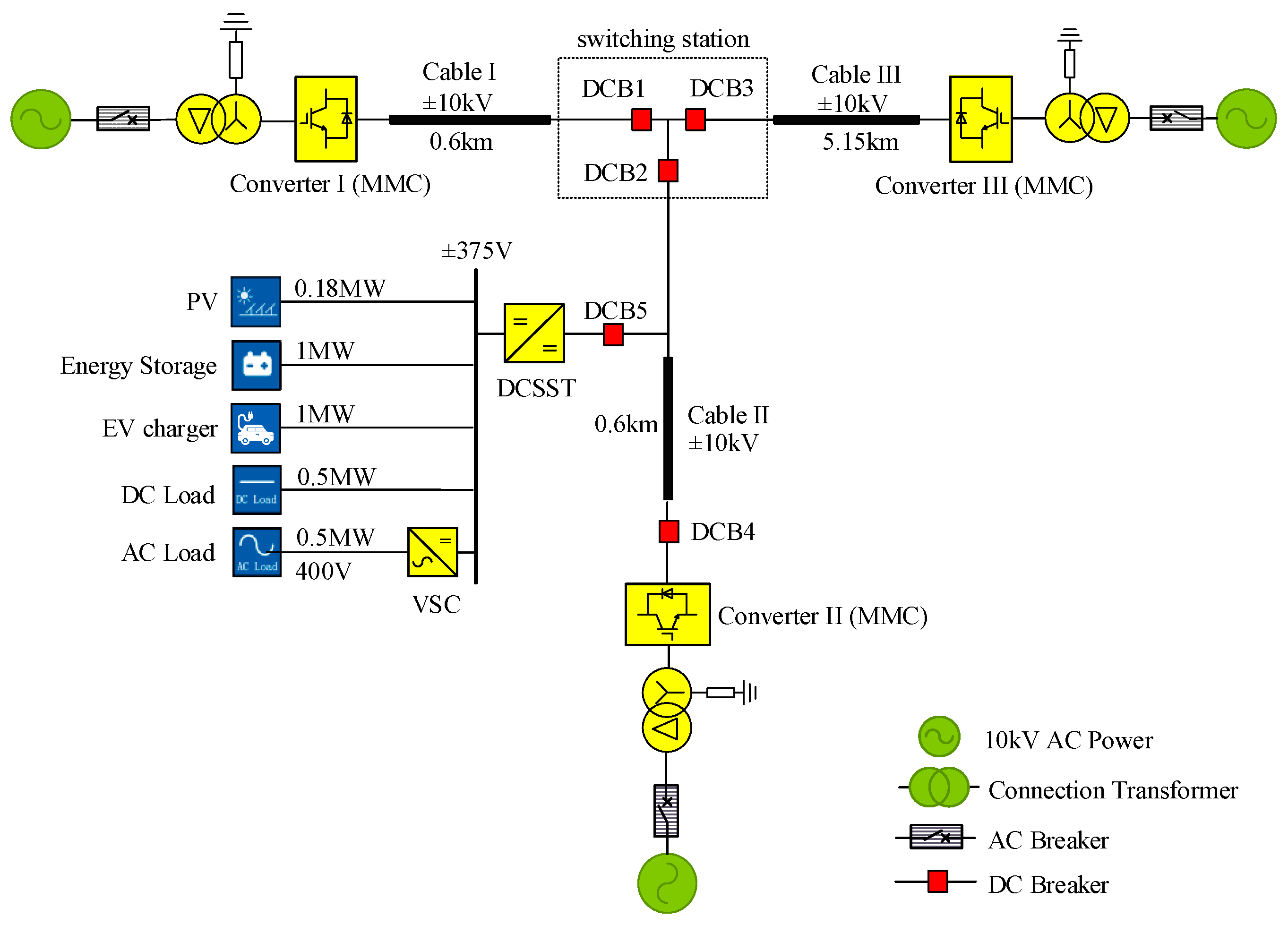
The analysis of this paper is based on the Tangjia Bay VSC-MTDC distribution network project. The project is the world’s first ±10 kV, ±375 V, and ±110 V multivoltage grade AC/DC hybrid distribution network project. It is also the largest converter station of ±10 kV DC distribution network in the world. This project consists of three flexible DC converter stations and one DC microgrid, which are connected by underground cables. Figure 1 shows the topological structure of this ±10 kV three-terminal flexible DC distribution system, which adopts a unipolar symmetrical type. The three main converter stations all adopt the modular multilevel converter (MMC). The converter station I adopts a full-bridge submodule with fault self-clearing capability; while station II and the station III adopt a half-bridge type submodule. The parameters of the three converters are shown in Table 1.
Under the normal three-terminal operation mode, converter station I and converter station II work as the sending ends and operate in the constant active power control mode. Converter station III works as the receiving end and operates in the constant voltage control mode.
2.2. DC Breaker Configuration and Protection Strategy
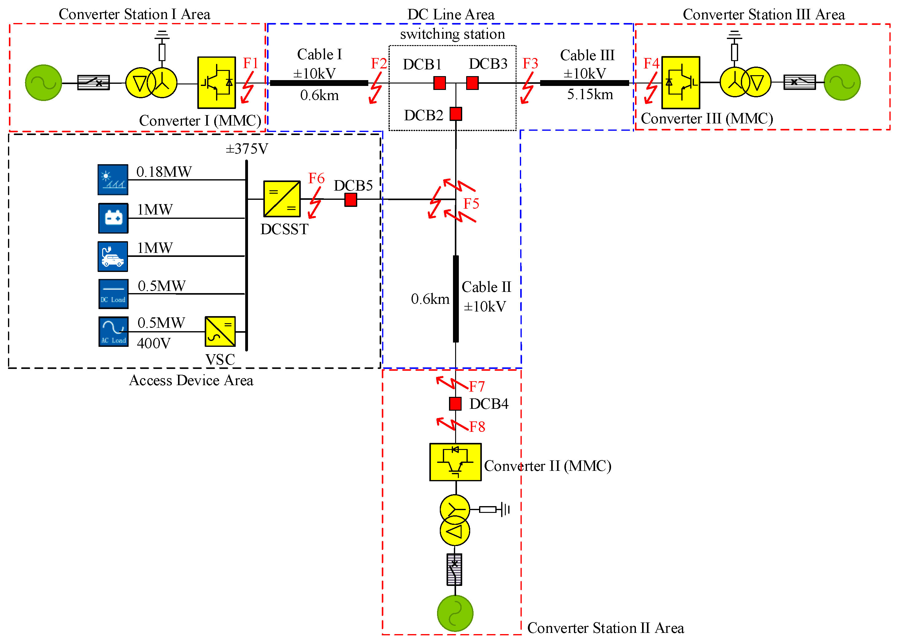
Figure 2 shows the configuration of DC breakers and typical pole-to-pole short-circuit faults on the DC side of the ±10 kV three-terminal flexible DC distribution system. In order to distinguish faults locations, the system is divided into converter station area, DC line area, and access device area based on the key equipment and protection strategies of the system. The converter station I area and the converter station III area are not equipped with any DC breaker, and the possible pole-to-pole short-circuit faults are F1 and F4. In order to ensure the power supply reliability of DC load, DCB4 is set in the area of converter station II, and the possible pole-to-pole short-circuit faults are F7 and F8. DC line and switch station area is equipped with triple-break DC breaker, the possible faults are F2, F3, and F5. DCB5 is set in the access device area, and the possible fault is F6. Typical pole-to-pole short-circuit faults and the fault clearance strategy are shown in Table 2.
The DC breakers used in this system have the ability to cut the current less than 10 kA within 3 ms. It is known by the protection strategy that it will take 2 ms for the protection system to detect the fault and send the signal after the fault occurs. Then, it will take 3 ms for the DC breaker to cut off the fault current. Therefore, the design principle of the current limiting reactor is to limit the DC breaker current less than 10 kA within 5 ms after the fault occurs under any faults.
3. Theoretical Analysis
3.1. Fault Discharge Circuit Analysis
According to the existing research, after the pole-to-pole short-circuit fault occurs in any position on the DC side of the flexible DC system, the submodule capacitor of each converter station will immediately discharge through the short-circuit point. The voltage-stabilizing capacitor on the high-voltage side of the DC transformer will also discharge through the short-circuit point, generating a large short circuit current. As a result, the current of each key device after the occurrence of pole-to-pole fault may be the superposition of the converters discharge current and the DC transformer discharge current. Therefore, it is necessary to study the transient characteristics, calculation methods, and influencing factors of the DC breaker fault current under various typical faults, so as to obtain a reasonable current limiting scheme.
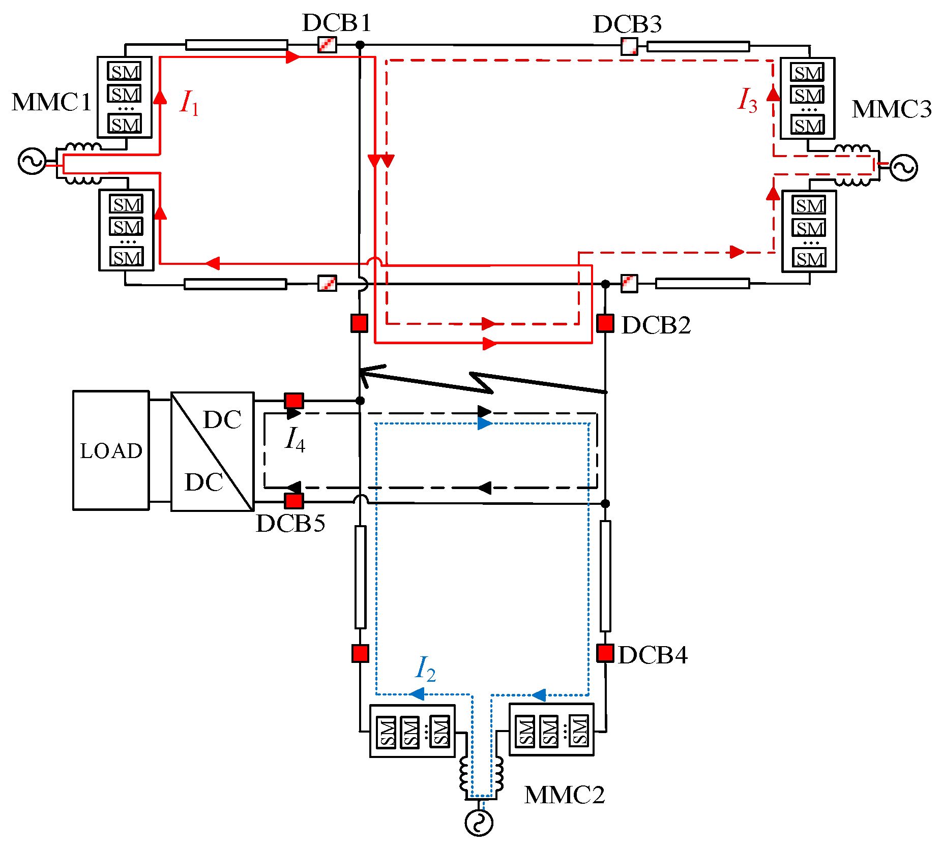
Firstly, taking the pole-to-pole fault F2 in Figure 2 as an example to analyze the fault equivalent discharge circuit, the result is shown in Figure 3. After the fault occurs, the submodule capacitors discharge immediately through the short-circuit point before the blocking of the converter station I, which causes the current of converter valve to rise rapidly. At the same time, the submodule capacitor of the other two converter stations and the voltage-stabilizing capacitor of DC transformer will also inject current into the circuit through the short-circuit point. I1, I2, I3, and I4 represent the discharge current of converter station I, converter station II, converter station III, and DC transformer to the short-circuit point, respectively.
According to Table 2, the fault will be removed by DCB1 under fault F2. Figure 3 shows that the fault current IDCB1 in DCB1 is composed of the capacitor discharge current I2 of converter station II, capacitor discharge current I3 of converter station III, and high-voltage side capacitor discharge current I4 of DC transformer.
Secondly, the F5 fault is taken as the next example for analysis, and the equivalent discharge circuit is shown in Figure 4. According to the Table 2, the fault will be removed by DCB2, DCB4 and DCB5. In this case, the fault current IDCB2 is composed of the discharge current I1 of the converter station I, the discharge current I3 of the converter station III. While the fault current IDCB4 is the discharge current I2 of converter station II and the fault current IDCB5 is the discharge current I4 of the DC transformer.
On the basis of the above analysis method, the generating mechanism of the DC breaker current under different fault conditions are summarized in Table 3. As can be seen from Figure 2 and Table 2, F2 and F1 have the same fault clearance strategy, but the overcurrent is more serious in F2 because of the discharge of the cable capacitor. As a result, F2 is chosen as the decisive fault type of the DCB1. Similarly, compared to F1, F3 will be selected as a decisive fault type of DCB3.
3.2. Equivalent Calculation of DC Breaker Fault Current
This section analyzes the calculation methods of discharge currents I1, I2, I3, and I4, respectively. The short-circuit current before the converter blocking is mainly comes from the submodule capacitor discharge current. This process can be equivalent to a second-order discharge circuit, which can be expressed and solved by differential equations. Since the time constants of the three capacitor discharge equivalent circuits of converter station I, converter station II and DC transformer are almost equal to each other, the three discharge circuits can be analyzed independently. The discharge circuit of the MMC converter is shown in Figure 5.
In Figure 5, L0 is the bridge arm reactor, C0 is the submodule capacitor value, Rf is the conduction losses of the power electronics switch, Rs is the short-circuit contact resistor, and Rd is the on-resistor of DC breaker. Rx, Lx, and Cx are the equivalent resistor, equivalent reactor, and equivalent capacitor of the DC line, respectively. The specific circuit parameters shown in the Figure 5 are calculated as follows
I4 is the discharge current of the high-voltage side capacitor of the DC transformer, and this circuit can also be equivalent to a second-order discharge circuit, as shown in Figure 6. Where C is the high-voltage side capacitor of the DC transformer, L is the stray reactor, the equivalent resistor R is the sum of the short-circuit contact resistor RS, the DC cable line equivalent resistor is RL, and the DC breaker on-resistor is Rd.
According to the initial conditions of the second-order circuit and the equivalent circuit shown in Figure 4 and Figure 5, the calculation formula of the circuit current i can be obtained:
where Udc is the initial voltage across poles, I0 is line current, ω is the angular frequency of the oscillating discharge current, and δ is the time constant.
Based on the fault equivalent circuit analysis results and the theoretical calculation formula, the fault current peak value and rise time of the acting DC breaker under various typical pole-to-pole short-circuit faults can be obtained. The calculation results are shown in Table 4.
3.3. Influencing Factors and Current Limiting Reactor Design Sequence
3.3.1. Influencing Factors of DC Breaker Fault Current
It can be seen that for any MTDC distribution system the influencing factors of the DC breaker fault current include the number of discharge currents and the parameters of each device in a single discharge circuit. It is obvious that the more discharge currents flow through the DC breaker, the greater the current will be. In a single discharge circuit, the influencing factors include the submodule capacitor, submodule topology, the line length, fault position, bridge reactor, and so on. However, in other practical projects, the influencing factors and current limiting schemes of DC circuit breaker fault current should be analyzed in combination with the actual topology and parameters of specific project.
For this typical three-terminal DC distribution system, the influencing factors can be analyzed from the following situations.
In fault F2, the submodule capacitor value of the converter station III is larger than that of the converter station II. However, I3 is less than I2 in Table 4, this can be explained by the longer length of line 3, which will make the impedance increase, and the current will be decreased.
The converter parameters and line parameters of station I and station II are symmetric with respect to the short-circuit point in fault F3. However, the full-bridge submodule is adopted in station I, and the number of power electronic switches and the on-resistor are twice that of the converter station II. As a result, the discharge current I1 is slightly smaller than I2.
F5 and F7 have the same clearance strategy, and the fault current of each DC breaker is generated for the same reason. However, because of the different fault locations and different line lengths, the equivalent impedance will be different. As a result, it will cause the different peak value and rise time of each DC breaker current in F5 and F7.
It can be concluded that the increase of the capacitor value of the submodule will lead to the increase of discharge current, while increase of the bridge reactor value or line length may result in a reduction in the fault current. Additionally, the discharge current of full-bridge submodule converter with the same parameters is less than that of half-bridge submodule converter, which is due to the increase in the number of power electronic switches.
3.3.2. Design Sequence of Current Limiting Reactor
For a VSC-MTDC distribution system, the current flowing through the acting DC breaker may be the superposition of the discharge current of the main converter stations and the DC transformer. Therefore, the current limiting devices should be configured at each main converter station outlet and DC transformer outlet to limit the current of each discharge circuit, and then they work together to limit the DC breaker current to meet the breaking capacity requirements. Considering the economical and space limitation factors, the current limiting reactor is selected to limit the fault current of each device in the system.
Since the number N of discharge currents flowing through the acting DC breakers under typical faults is different, the required limiting current and the current limiting difficulties are also distinct. For this system (a four-terminal discharge system including DC transformer), the discharge current of any three discharge devices can flow through the acting DC breaker at the same time. Meanwhile, the effect of the current limiting reactor has a saturation trend, the larger the current limiting reactor, the weaker the unit current limiting effect. It should also be considered that excessive current limiting inductance at one terminal may cause system stability to deteriorate. Therefore, the required limiting current IN of each single discharge circuit should be averaged by the DC breaker breaking current as the following formula.
where Ik is the maximum breaking current of the DC breaker.
Comparison of fault current and required limiting current of each circuit under typical faults is shown in Table 5.
Table 5 shows that the current of the acting DC breaker has three sources (N = 3) in faults F2, F3, F6, and F8. The maximum breaking current of the DC breaker in the three terminal DC distribution system is 10 kA, and so the current in each discharge circuit of the three sources should be limited to 3.33 kA or less. Multiple DC breakers will act to clear the fault in fault F5 and F7. There is only one current source for acting breaker DCB4 and DCB5 in fault F5 and F7, so the required limiting current for I2 and I4 are 10 kA; while DCB2 has two current sources, I1 and I3 are required to be 5 kA.
Therefore, although the I4 current peak value under F5 fault is very high, considering the required limiting current of each circuit and the saturation of reactor current limiting capacity, the F3 fault has the greatest difficulty in limiting the current of each discharge circuit, and the current limiting difficulty of F2 is the second.
Based on the theoretical analysis results, the calculation sequence of the current limiting reactor parameters is proposed. Firstly, the F3 fault with the largest current limiting difficulty should be selected to determine the current limiting reactor parameters of the converter station I, the converter station II, and the DC transformer. Then, the F2 fault with the second highest difficulty of current limiting should be selected to determine the value of current limiting reactor at the outlet of the converter station III. Finally, the parameters of current limiting reactor should be verified by all the other faults to see whether it meets all the requirements.
4. Simulation Analysis
4.1. Simulation Modeling and Verification
According to the system topology and key equipment parameters, the electromagnetic transient model of the ±10 kV three-terminal flexible DC distribution system is built by using the PSCAD/EMTDC, in which DC load is equivalent to controllable current source and AC load is equivalent to resistive load.
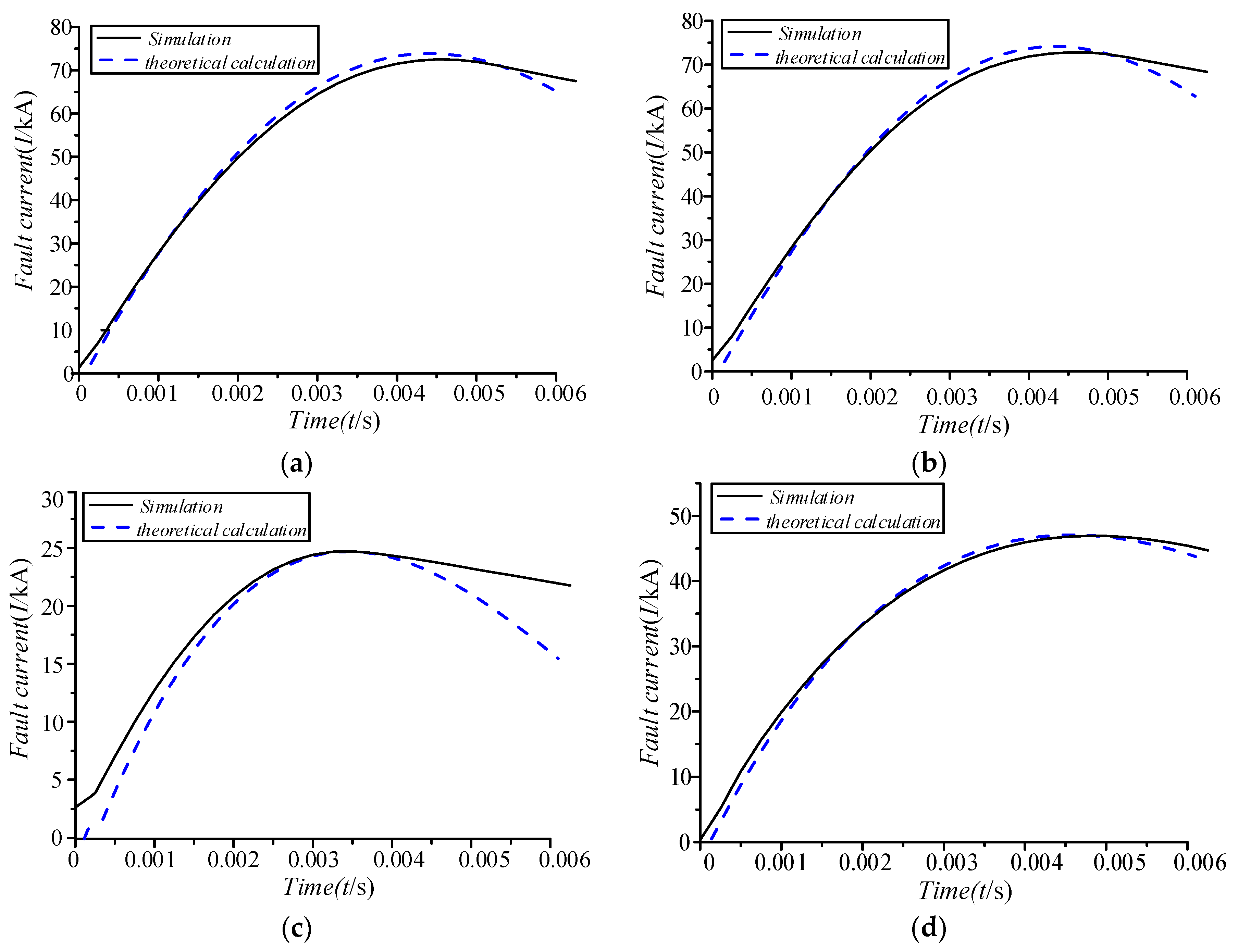
In order to verify the theoretical analysis results, the acting DC breaker fault currents under F2, F3, F6, and F8 faults with multiple discharge circuits were simulated and compared with the theoretical calculation results. The results are shown in Figure 7.
It can be seen that the theoretical analysis and the simulation result have little difference in Figure 7. The discharge process of each circuit is regarded as independent in 3.2 in the theoretical analysis. However, each discharge circuit is actually affected by certain mutual influence, which is the main reason for the difference between the analytical and simulation results.
4.2. Current Limiting Reactor Parameter Design
Firstly, current limiting reactors are designed and configured for converter station I, converter station II, and the DC transformer outlet, respectively, in the F3 fault. It is known that the higher reactor value of the current-limiting reactor is, the smaller the fault current becomes; however, the economical efficiency is difficult to achieve if the reactor value is too high. Therefore, the simulation method is used to calculate the appropriate reactor value. Table 6, Table 7 and Table 8 show that the discharge current of each circuit decreases with the increase of the reactor value, however, the current limiting effect has a saturation trend. The minimum reactor that can limit the discharge current (within 5 ms) to 3.33 kA is proposed at last.
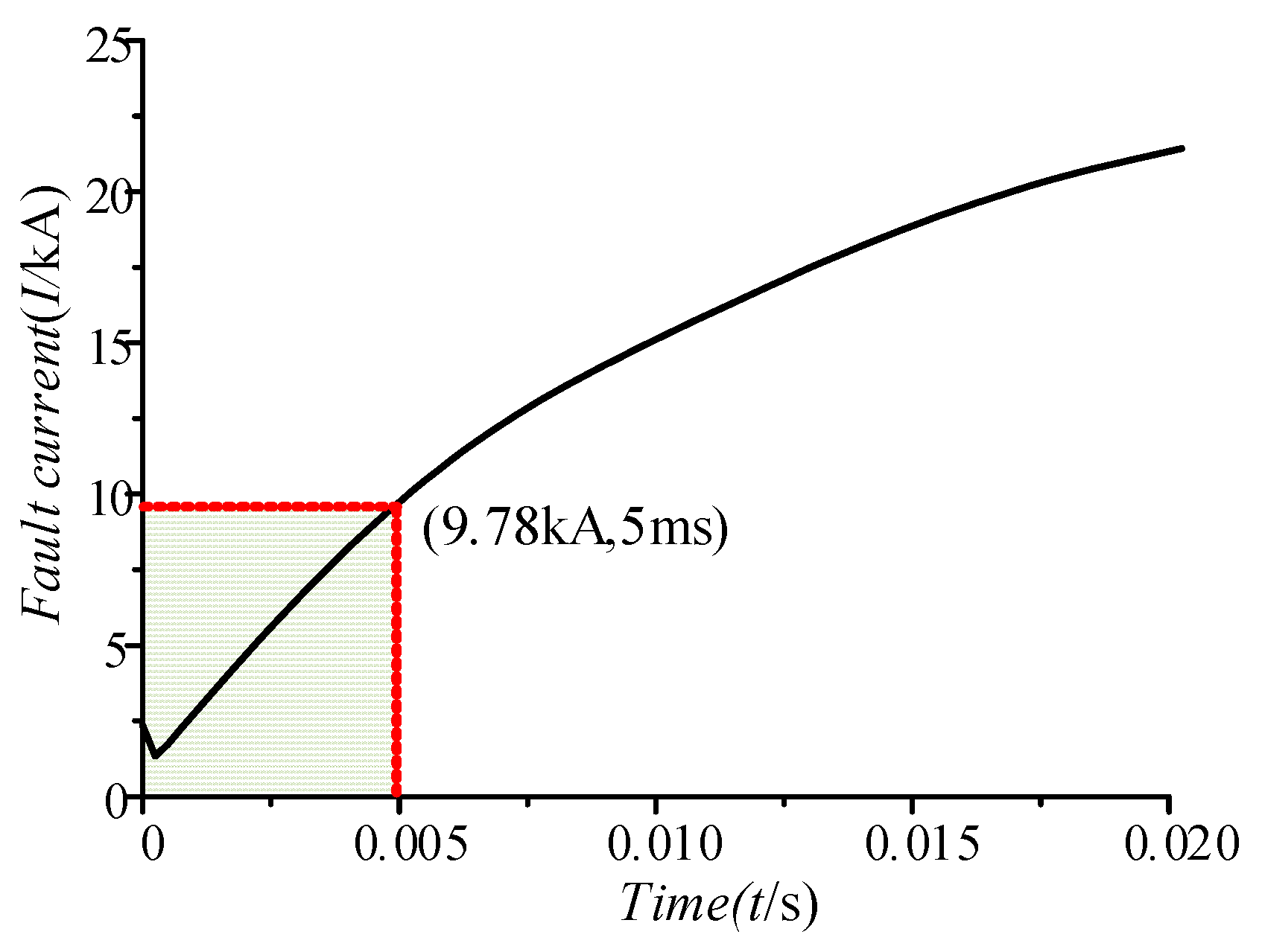
The 13 mH (each pole), 13 mH (each pole), and 15 mH (each pole) reactors are proposed to be respectively configured at the high-voltage side outlet of converter station I, converter station II, and DC transformer, and the discharge currents of the three discharge circuits under the F3 fault can be reduced to be less than 3.33 kA. Under this condition, the fault current IDCB3 flowing through DCB3 of DC breaker is shown in Figure 8.
It can be seen from Figure 8 that after the fault occurs, the transient current IDCB3 flowing through DCB3 reaches to 9.74 kA within 5 ms, and this will meet the requirements of the breaking capacity of the DC breaker.
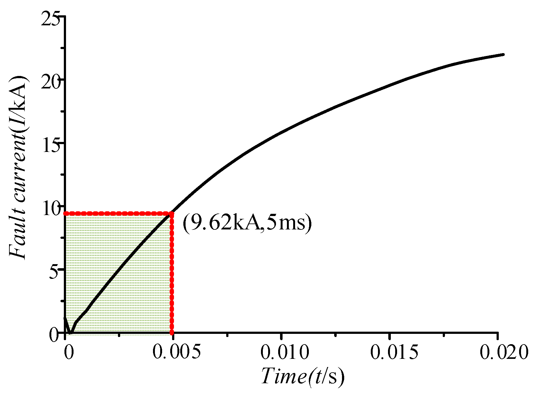
On the basis that the current limiting reactor of the converter station I, the converter station II, and the DC transformer outlet have been configured, the reactor value of the converter station III in F2 fault is then calculated. The results show that when the reactor value of the current limiting reactor at outlet of the converter station III is 9 mH each pole, the maximum current within 5 ms in this circuit is 3.16 kA. The fault current IDCB1 flowing through DCB1 is shown in Figure 9 when the 9 mH reactor is configured in each pole.
Figure 9 shows that the transient current IDCB3 flowing through DCB3 reaches maximum value 9.62 kA within 5 ms, meeting the requirements of the DC breaker breaking capacity.
In summary, the system current limiting reactor design scheme and its parameters are shown in Table 9.
4.3. Verification of the System Current Limiting Reactor Scheme
4.4. Influence of Current Limiting Reactors on Transient Characteristics of the System
In order to analyze the influence of the current limiting reactor on the transient characteristics of the system, the interaction between the AC system and the DC system is studied from the perspective of fault overvoltage and overcurrent firstly. The simulation results show that the configuration of the current limiting reactor does not affect the access mode of DC/AC system. When the DC distribution network is connected to the AC network through the coupled transformer; the AC/DC system has little interaction with each other under one side fault.
Secondly, the influence of current limiting reactor on the overvoltage of the system is also studied. Due to the energy storage characteristics of the reactor, when the current of the reactor has a sudden change, overvoltage will be generated on the reactor, and the larger the current change rate is, the larger the overvoltage will be. Especially in the case of pole-to-pole short-circuit fault, the current flowing through the reactor will drop to zero instantaneously when the DC breaker acts. Therefore, a severe overvoltage will be generated on the current limiting reactor and further causes an overvoltage on the DC line side of the system, and the insulation level of the equipment should be carefully considered and designed.
5. Conclusions
In this paper, theoretical calculation and simulation analysis are carried out for the DC breaker fault current generation mechanism and its limiting method of a ±10 kV three-terminal flexible DC distribution system, the following conclusions are obtained.
(1) The transient characteristics and influencing factors of the DC breakers fault current are analyzed theoretically. When the short-circuit fault occurs at any position on the DC side, the capacitor of each main converter station and the access device will quickly discharge through the short-circuit point. The DC breaker fault current can be obtained by superimposing the calculation results of all equivalent second-order circuits. The topology of the main converter, line parameters, and the main converter parameters, such as the equivalent capacitor and bridge reactor, will directly affect the discharge current of each part.
(2) Based on the theoretical analysis, it is proposed to configure current limiting reactor at each main converter outlet and the high-voltage side of the access device to limit the discharge current of each discharge circuit. According to the transient characteristics and influencing factors of the DC breaker fault current, the calculation method and calculation sequence of the current limiting reactor parameters are proposed.
(3) The theoretical analysis results are verified by electromagnetic transient simulation, and the current limiting reactor parameters are calculated by simulation: For the three-terminal flexible DC distribution system, it is proposed that the outlets of the converter station I, the converter station II, the converter station III, and the high-voltage side of the DC transformer is configured with the current limiting reactor with 13 mH (each pole), 13 mH (each pole), 9 mH (each pole), and 15 mH (each pole) respectively. Finally, the reliability of the current limiting scheme is verified by simulation analysis of other typical faults and the influence of current limiting reactors on transient characteristics of system is analyzed.
Author Contributions
Conceptualization, Y.H. and J.Z.; Methodology, Y.H. and J.Z.; Software, J.Z.; Validation, Y.G.; Formal Analysis, F.X.; Investigation, F.X.; Resources, J.Z.; Data Curation, Y.G.; Writing—Original Draft Preparation, J.Z.; Writing—Review & Editing, Y.H.; Visualization, X.L. and L.L; Supervision, Y.H.; Project Administration, Y.H.; Funding Acquisition, F.G.
Funding
This research and APC were funded by [National Natural Science Foundation of China] grant number [51807068].
Conflicts of Interest
The authors declare no conflict of interest.
References
- Hossain, M.R.; Iii, H.G. Real-time Distributed Coordination of Power Electronic Converters in a DC Shipboard Distribution System. IEEE Trans. Power Appar. Syst. 2017, 32, 770–778. [Google Scholar] [CrossRef]
- Flourentzou, N.; Agelidis, V.G.; Demetriades, G.D. VSC-Based HVDC Power Transmission Systems: An Overview. IEEE Trans. Power Electron. 2009, 24, 592–602. [Google Scholar] [CrossRef]
- Li, Q.; Antoniazzi, A.; Raciti, L. DC Distribution Fault Analysis, Protection Solutions, and Example Implementations. IEEE Trans. Ind. Appl. 2018, 54, 3179–3186. [Google Scholar]
- Baran, M.; Mahajan, N.R. DC distribution for industrial systems: Opportunities and challenges. In Proceedings of the IEEE Industrial & Commerical Power Systems Technical Conference, Savannah, GA, USA, 5–8 May 2002. [Google Scholar]
- Song, Q.; Zhao, B.; Liu, W. An overview of research on smart DC distribution power network. Proc. CSEE 2013, 33, 9–19. [Google Scholar]
- Tang, G.; Luo, X.; Wei, X. Multi-terminal HVDC and DC-grid technology. Proc. CSEE 2013, 33, 8–17. [Google Scholar]
- Adam, G.P.; Anaya-Lara, O.; Burt, G. Multi-terminal DC transmission system based on modular multilevel converter. In Proceedings of the 2009 IEEE 44th International Universities Power Engineering Conference (UPEC), Glasgow, UK, 1–4 September 2009. [Google Scholar]
- Chang, B.; Cwikowski, O.; Barnes, M.; Shuttleworth, R. Multi-terminal VSC-HVDC Pole-to-pole Fault Analysis and Fault Recovery Study. In Proceedings of the IET International Conference on AC & DC Power Transmission, Birmingham, UK, 10–12 February 2015. [Google Scholar]
- Xu, J.; Zhao, P.; Zhao, C. Reliability Analysis and Redundancy Configuration of MMC with Hybrid Sub-module Topologies. IEEE Trans. Power Electron. 2015, 31, 2720–2729. [Google Scholar] [CrossRef]
- Huang, L.; Yang, X.; Xu, P.; Zhang, F.; Ma, X.; Liu, T.; Hao, X.; Liu, W. The evolution and variation of sub-module topologies with DC-fault current clearing capability in MMC-HVDC. In Proceedings of the IEEE Future Energy Electronics Conference & Ecce Asia, Kaohsiung, Taiwan, 3–7 June 2017. [Google Scholar]
- Marquardt, R. Modular Multilevel Converter topologies with DC-Short circuit current limitation. In Proceedings of the IEEE International Conference on Power Electronics & Ecce Asia, Jeju, Korea, 30 May–3 June 2011. [Google Scholar]
- Konstantinou, G.S.; Ciobotaru, M.; Agelidis, V.G. Effect of redundant sub-module utilization on modular multilevel converters. In Proceedings of the IEEE International Conference on Industrial Technology, Athens, Greece, 19–21 March 2012. [Google Scholar]
- Xiang, W.; Li, W.; Wen, J. A New Topology of Sub-modules with DC Fault Current Blocking Capability and a New type of Hybrid MMC Converter. Proc. CSEE 2014, 34, 5171–5179. [Google Scholar]
- Xu, Z.; Xu, Y.; Zhang, Z. VSC-HVDC Technology Suitable for Bulk Power Overhead Line Transmission. Proc. CSEE 2014, 34, 5051–5062. [Google Scholar]
- Lin, W.; Jovcic, D. LCL and L-VSC Converters with DC Fault Current-Limiting Property and Minimal Power Losses. IEEE Trans. Power Deliv. 2014, 29, 2359–2368. [Google Scholar] [CrossRef]
- Bathurst, G.; Bordignan, P. Delivery of the Nan’ao multi-terminal VSC-HVDC system. In Proceedings of the IET International Conference on AC & DC Power Transmission, Birmingham, UK, 10–12 February 2015. [Google Scholar]
- Rao, H. Architecture of Nan’ao multi-terminal VSC-HVDC system and its multi-functional control. CSEE J. Power Energy Syst. 2015, 1, 9–18. [Google Scholar] [CrossRef]
- Li, B.; He, J. DC Fault Analysis and Current Limiting Technique for VSC-based DC Distribution System. Proc. CSEE 2015, 35, 3026–3036. [Google Scholar]
- Komatsu, M. Approach and basic evaluation for the DC circuit breaker with fault current limiting feature. In Proceedings of the IEEE Telecommunications Energy Conference, Austin, TX, USA, 23–27 October 2016. [Google Scholar]
- Li, B.; He, J. Research on the DC Fault Isolating Technique in Multi-terminal DC System. Proc. CSEE 2016. [Google Scholar] [CrossRef]
- Geebelen, B.; Leterme, W.; Hertem, D.V. Analysis of DC breaker requirements for different HVDC grid protection schemes. In Proceedings of the IET International Conference on AC & DC Power Transmission, Birmingham, UK, 10–12 February 2015. [Google Scholar]
- Guo, Z.; Han, Y.; Zhao, Y. Study on Transient Current of the Key Equipment in Flexible DC Power Distribution System. High Volt. Eng. 2017, 43, 1280–1288. [Google Scholar]
- Janowski, T.; Glowacki, B.A.; Wojtasiewicz, G.; Kozak, S.; Kozak, J.; Kondratowicz-Kucewicz, B.; Majka, M.; Woźniak, M. Fault Current Limitation in Power Network by the Superconducting Transformers Made of 2G HTS. IEEE Trans. Appl. Supercond. 2011, 21, 1413–1416. [Google Scholar] [CrossRef]
- Moriconi, F.; Rosa, F.D.L.; Darmann, F. Development and Deployment of Saturated-Core Fault Current Limiters in Distribution and Transmission Substations. IEEE Trans. Appl. Supercond. 2011, 21, 1288–1293. [Google Scholar] [CrossRef]
Figure 1.
Topology of the ±10 kV three-terminal DC distribution system.

Figure 2.
DC breaker configuration and pole-to-pole short circuit fault location.

Figure 3.
Equivalent circuit of pole-to-pole fault F2.

Figure 4.
Equivalent circuit of pole-to-pole fault F5.

Figure 5.
Equivalent discharge circuit of main converter capacitor.

Figure 6.
Equivalent discharge circuit of DC transformer.

Figure 7.
Comparison of theoretical calculations and simulation results. (a) Fault current of DCB1 under Fault F2. (b) Fault current of DCB3 under Fault F3. (c) Fault current of DCB5 under Fault F6. (d) Fault current of DCB4 under Fault F8.
Figure 7.
Comparison of theoretical calculations and simulation results. (a) Fault current of DCB1 under Fault F2. (b) Fault current of DCB3 under Fault F3. (c) Fault current of DCB5 under Fault F6. (d) Fault current of DCB4 under Fault F8.

Figure 8.
Fault current of DCB3 under Fault F3.

Figure 9.
Fault current of DCB1 under Fault F2.

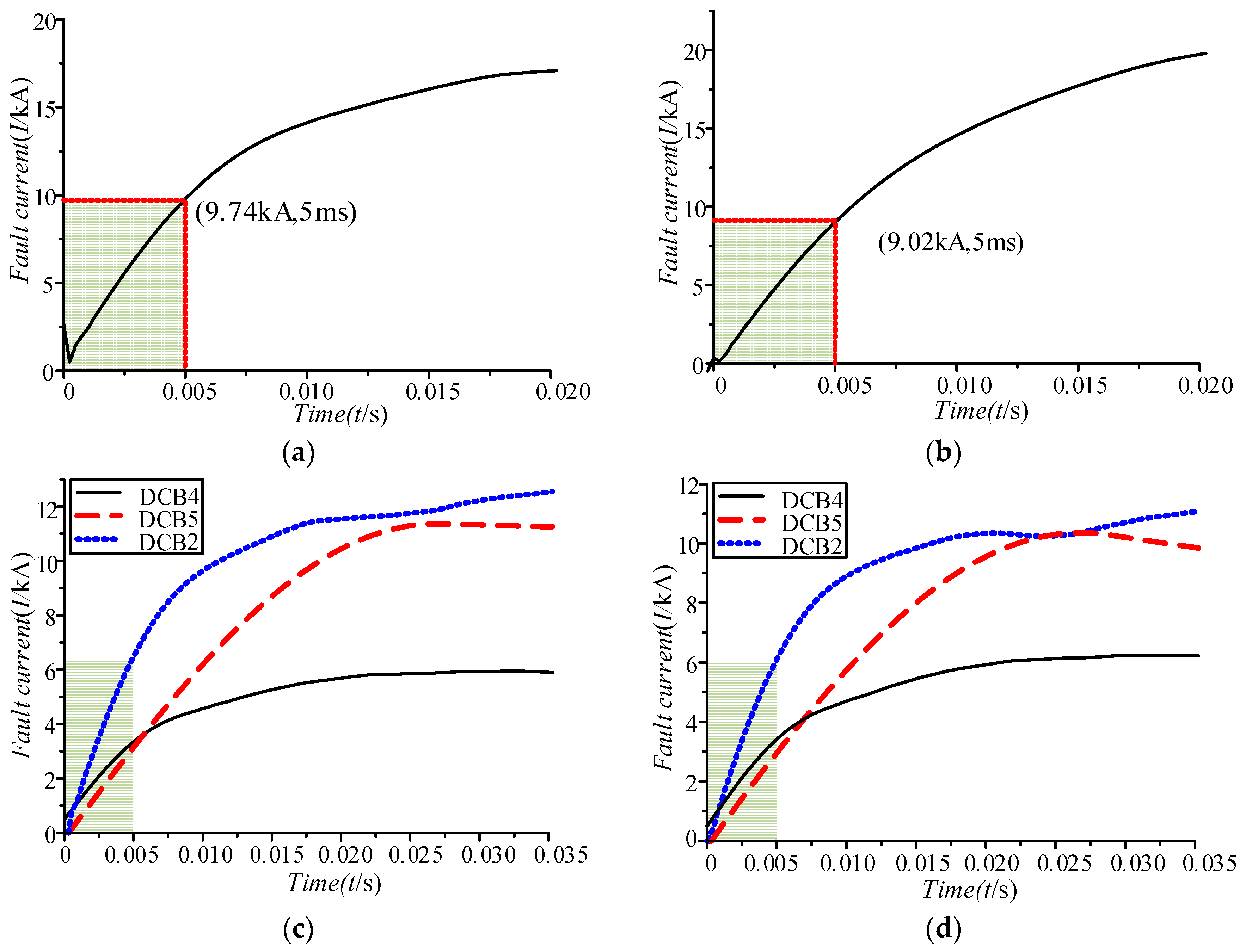
Figure 10.
DC breaker fault currents of F5–F8. (a) Fault current of DCB5 under Fault F6. (b) Fault current of DCB4 under Fault F8. (c) Fault currents of DCB2, DCB4, and DCB5 under Fault F5. (d) Fault currents of DCB2, DCB4, and DCB5 under Fault F7.
Figure 10.
DC breaker fault currents of F5–F8. (a) Fault current of DCB5 under Fault F6. (b) Fault current of DCB4 under Fault F8. (c) Fault currents of DCB2, DCB4, and DCB5 under Fault F5. (d) Fault currents of DCB2, DCB4, and DCB5 under Fault F7.


Table 1.
Parameters of converter stations in the three-terminal DC distribution system.
| Items | Converter I | Converter II | Converter III |
|---|---|---|---|
| Main connection scheme | Full-bridge MMC; Symmetrical monopole | Half-bridge MMC; Symmetrical monopole | Half-bridge MMC; Symmetrical monopole |
| Rated capacity (MVA) | 10 | 10 | 20 |
| DC rated voltage (kV) | ±10 | ±10 | ±10 |
| DC rated current (kA) | 0.5 | 0.5 | 1.0 |
| Number of single bridge arm submodule | 22 | 22 | 22 |
| Bridge arm reactor (mH) | 6 | 6 | 3 |
| Submodule capacity (mF) | 0.6 | 0.6 | 1.1 |
Table 2.
System fault clearing strategy.
| Fault Location | Acting DC Breaker |
|---|---|
| F1, F2 | DCB1 |
| F3, F4 | DCB3 |
| F5, F7 | DCB2, DCB4, DCB5 |
| F6 | DBC5 |
| F8 | DCB4 |
Table 3.
DC breaker fault current condition under typical pole-to-pole short circuit fault.
| Fault Type | Acting DC Breaker | DC Breaker Fault Current |
|---|---|---|
| F2 | DCB1 | IDCB1 = I2 + I3 + I4 |
| F3 | DCB3 | IDCB3 = I1 + I2 + I4 |
| F5 | DCB2 | IDCB2 = I1 + I3 |
| DCB4 | IDCB4 = I2 | |
| DCB5 | IDCB5 = I4 | |
| F6 | DCB5 | IDCB5 = I1 + I2 + I3 |
| F7 | DCB2 | IDCB2 = I1 + I3 |
| DCB4 | IDCB4 = I2 | |
| DCB5 | IDCB5 = I4 | |
| F8 | DCB4 | IDCB4 = I1 + I3 + I4 |
Table 4.
Theoretical calculation results of DC breaker fault current.
| Fault Type | Discharge Current | Peak Value (kA) | Peak Time (ms) | Acting DC Breaker Current | Peak Value (kA) | Peak Time (ms) |
|---|---|---|---|---|---|---|
| F2 | I2 | 8.58 | 3.4 | IDCB1 | 73.85 | 4.4 |
| I3 | 7.81 | 3.4 | ||||
| I4 | 58.76 | 4.7 | ||||
| F3 | I1 | 8.31 | 3.4 | IDCB3 | 74.14 | 4.4 |
| I2 | 8.58 | 3.4 | ||||
| I4 | 58.76 | 4.7 | ||||
| F5 | I2 | 8.62 | 3.5 | IDCB4 | 8.62 | 3.5 |
| I4 | 60.09 | 4.7 | IDCB5 | 60.09 | 4.7 | |
| I1 | 8.31 | 3.4 | IDCB2 | 16.11 | 3.4 | |
| I3 | 7.80 | 3.4 | ||||
| F6 | I1 | 8.34 | 3.4 | IDCB5 | 24.73 | 3.4 |
| I2 | 8.58 | 3.4 | ||||
| I3 | 7.80 | 3.4 | ||||
| F7 | I2 | 9.73 | 3.5 | IDCB4 | 9.73 | 3.5 |
| I4 | 35.66 | 5.3 | IDCB5 | 35.66 | 5.3 | |
| I1 | 5.73 | 3.1 | IDCB2 | 11.04 | 3.5 | |
| I3 | 5.52 | 4.4 | ||||
| F8 | I1 | 5.72 | 3.1 | IDCB4 | 46.90 | 4.7 |
| I3 | 4.87 | 4.4 | ||||
| I4 | 34.2 | 5.2 |
Table 5.
Comparison of fault current and required limiting current of each circuit.
| Fault Type | Discharge Current | Peak Value (kA) | Acting DC Breaker | Required Limiting Current (kA) |
|---|---|---|---|---|
| F2 | I2 | 8.58 | DCB1 | 3.3 |
| I3 | 7.81 | 3.3 | ||
| I4 | 58.76 | 3.3 | ||
| F3 | I1 | 8.31 | DCB3 | 3.3 |
| I2 | 8.58 | 3.3 | ||
| I4 | 58.76 | 3.3 | ||
| F5 | I2 | 8.62 | DCB4 | 10 |
| I4 | 60.09 | DCB5 | 10 | |
| I1 | 8.31 | DCB2 | 5 | |
| I3 | 7.80 | 5 | ||
| F6 | I1 | 8.34 | DCB5 | 3.3 |
| I2 | 8.58 | 3.3 | ||
| I3 | 7.80 | 3.3 | ||
| F7 | I2 | 9.73 | DCB4 | 10 |
| I4 | 35.66 | DCB5 | 10 | |
| I1 | 5.73 | DCB2 | 5 | |
| I3 | 5.52 | 5 | ||
| F8 | I1 | 5.72 | DCB4 | 3.3 |
| I3 | 4.87 | 3.3 | ||
| I4 | 34.2 | 3.3 |
Table 6.
Discharge current I1 under different current limiting reactor of converter station I.
| Reactor of Each Pole (mH) | Current Peak (kA) | Peak Time (ms) | Current Peak (Whithin 5 ms) |
|---|---|---|---|
| 1 | 7.16 | 4.0 | 7.16 |
| 3 | 6.21 | 6.2 | 6.12 |
| 5 | 5.62 | 7.0 | 5.28 |
| 7 | 5.25 | 7.8 | 4.59 |
| 9 | 4.93 | 8.5 | 4.09 |
| 11 | 4.62 | 8.9 | 3.64 |
| 13 | 4.45 | 10 | 3.29 |
Table 7.
Discharge current I2 under different current limiting reactor of converter station II.
| Reactor of Each Pole (mH) | Current Peak (kA) | Peak Time (ms) | Current Peak (Whithin 5 ms) |
|---|---|---|---|
| 1 | 7.26 | 4.0 | 7.26 |
| 3 | 6.34 | 6.5 | 6.22 |
| 5 | 5.74 | 7.5 | 5.34 |
| 7 | 5.32 | 8.0 | 4.64 |
| 9 | 4.95 | 8.3 | 4.09 |
| 11 | 4.78 | 10 | 3.72 |
| 13 | 4.66 | 11 | 3.32 |
Table 8.
Discharge current I4 under different current limiting reactor of DC transformer.
| Reactor of Each Pole(mH) | Current Peak (kA) | Peak Time (ms) | Current Peak (Whithin 5 ms) |
|---|---|---|---|
| 1 | 41.68 | 6.8 | 38.36 |
| 3 | 24.70 | 12 | 15.23 |
| 5 | 19.25 | 15.3 | 9.33 |
| 7 | 16.24 | 17.5 | 6.78 |
| 9 | 14.41 | 20.5 | 5.26 |
| 11 | 13.04 | 22.5 | 4.27 |
| 13 | 12.00 | 24.2 | 3.68 |
| 15 | 11.14 | 25.5 | 3.15 |
Table 9.
System current limiting reactor configuration and parameters.
| Mounting Position | Reactor Value of Each Pole (mH) |
|---|---|
| Converter station I outlet | 13 |
| Converter station II outlet | 13 |
| Converter station III outlet | 9 |
| DC transformer outlet | 15 |
Table 10.
Fault current calculation result of each DC breaker.
| Fault Type | Acting DC Breaker | Current Peak (kA) | Peak Time (ms) | Current Peak (Within 5 ms) |
|---|---|---|---|---|
| F8 | DCB4 | 20.69 | 31 | 9.02 |
| F6 | DCB5 | 18.26 | 38 | 9.78 |
| F5 | DCB2 | 12.99 | 49.0 | 6.48 |
| DCB4 | 5.96 | 33.0 | 3.35 | |
| DCB5 | 11.36 | 26.5 | 3.05 | |
| F7 | DCB2 | 11.77 | 50 | 6.09 |
| DCB4 | 21.1 | 31.2 | 9.08 | |
| DCB5 | 10.36 | 26.6 | 2.95 |
© 2019 by the authors. Licensee MDPI, Basel, Switzerland. This article is an open access article distributed under the terms and conditions of the Creative Commons Attribution (CC BY) license (http://creativecommons.org/licenses/by/4.0/).
Share and Cite
MDPI and ACS Style
Zhang, J.; Gao, Y.; Xiao, F.; Guo, F.; Li, X.; Han, Y.; Li, L. Study on DC Breaker Fault Current and Its Limiting Method of Multiterminal Flexible DC Distribution System. Energies 2019, 12, 859. https://doi.org/10.3390/en12050859
AMA Style
Zhang J, Gao Y, Xiao F, Guo F, Li X, Han Y, Li L. Study on DC Breaker Fault Current and Its Limiting Method of Multiterminal Flexible DC Distribution System. Energies. 2019; 12(5):859. https://doi.org/10.3390/en12050859
Chicago/Turabian StyleZhang, Jinghan, Yuqun Gao, Fanglei Xiao, Fang Guo, Xinwei Li, Yongxia Han, and Licheng Li. 2019. "Study on DC Breaker Fault Current and Its Limiting Method of Multiterminal Flexible DC Distribution System" Energies 12, no. 5: 859. https://doi.org/10.3390/en12050859
Note that from the first issue of 2016, this journal uses article numbers instead of page numbers. See further details here.