Stability of Split-Level Gob-Side Entry in Ultra-Thick Coal Seams: A Case Study at Xiegou Mine


1
State Key Laboratory for GeoMechanics and Deep Underground Engineering, China University of Mining and Technology (Beijing), Beijing 100083, China
2
School of Energy and Mining Engineering, China University of Mining and Technology (Beijing), Beijing 100083, China
Energies 2019, 12(4), 628; https://doi.org/10.3390/en12040628
Submission received: 2 January 2019
/
Revised: 7 February 2019
/
Accepted: 14 February 2019
/
Published: 15 February 2019
Abstract
:Split-level longwall gob-side entry (SLGE) has been applied as a special form of small gate pillar mining (or non-coal pillar mining) in thick coal seams. The stability of the coal pillar directly affects the rationality of the layout of the SLGE. Starting from the mining-induced influence around the SLGE, this paper compares the mechanical properties of coal under different mining effects, and studies the rationality of “zero pillar” location against the Xiegou coal mine. The study shows that the key to success of the application of the SLGE is the existence of an intact zone within the triangular coal pillar in spite of double disturbances due to tunneling and coal mining extraction. Laboratory testing shows that the density and uniaxial compressive strength of rock specimens obtained from the triangular coal pillar are smaller than that from the other part of the panel which is concluded to be due to the varied degree of mining-induced influence. The numerical modeling results show that most of the triangular coal pillar is intact after extraction of the panel, and that the peak stress is located in the solid coal beyond the triangular coal pillar. The plastic zone of the triangular coal pillar is only about 1 m after the excavation of the tail gate of the next split-level panel. The physical modeling shows that the tail gate of the next panel is in the destressed zone with only a very small stress fluctuation during the extraction of the next panel. The study shows that the location of the SLGE at Xiegou coal mine is reasonable. SLGE is preferable for ultra-thick coal seams.
1. Introduction
Thick coal seam in China is abundant, accounting for about 44% of coal reserves. The production from thick coal seams accounted for about 45% of raw coal production. The coal seams are generally mined using the fully mechanized longwall top coal caving (FMLTCC) method. In spite of high production and high efficiency, the recovery is still low due to difficulty in recovering coal pillars and top-coal above the face ends. Gob-side entry is one of the solutions for this contradiction.
Scholars at home and abroad have made great progress in gob-side entry technology in FMLTCC. Hou and Li [1,2] proposed the stability control principle according to large and small structures in the surrounding rocks along the FMLTCC gob-side entry. Bai [3,4,5,6] studied the movement, deformation, and failure characteristics of the arc-shaped triangular plate and roadway surrounding rock of the FMLTCC gob-side entry at different stages to determine the location of the gob-side entry. He proposed the surrounding rock control mechanism for FMLTCC gob-side entry by using the reinforcement and strengthening theory for bolt-supported surrounding rock. Tan [7] analyzed the roof structure for the gob-side entry with an artificial wall. Using numerical modeling, Li [8] concluded that a 6 m coal pillar was fit for a FMLTCC gob-side entry in mining a 15 m-thick coal seam at Tashan mine. Based on measured pressure at the FMLTCC panel of Rujigou mine in Ningxia, Shi et al. [9] defined 4–6 m as a ”narrow coal pillar“ and 10–15 m as a ”wide coal pillar“, and pointed out that the ”narrow coal pillar“ only serves to isolate the panel from the gob. Using high-water quick-setting materials, Yang et al. [10] proposed a roadside backfill body (RBB) for an artificial wall for gob-side entry. Zhao et al. [11,12,13,14] proposed the split-level longwall panel layout (SLPL), investigated the layout configuration of the split-level longwall gob-side entry (SLGE), and put forward the “negative coal pillar”, “zero coal pillar”, and more reasonable small coal pillars as shown in Figure 1.
Although SLGE has been applied in many coal mines, the layout of the SLGE is still determined at random, or just arbitrarily, by experience gained from similar panels at the same or nearby coal mines. However, in fact, the stability of the triangular coal pillar in the elevated section has been shown to have a critical role in the stability of the entry next to it [15], especially in ultra-thick coal seams. In coal seams whose thicknesses are less than 8 m, the SLGE can only use steel sets for roof support due to the large range of the zone of influence within the surrounding rock mass, which hinders the fast tunneling speed of the entry. For ultra-thick coal seams whose thicknesses are more than 10 m, this is not the case because the range of the zone of influence within the surrounding rock mass cannot cover the whole thickness.
This paper, therefore, studies the mechanical properties of coal at different locations around the SLGE based on an analysis of the load-carrying behavior of coal at different mining stages. From the fracture cumulative effect point of view, the reasonable gob-side entry locations are analyzed. Stress and fracture evolutions of the pillar for different layouts are studied through physical modeling to provide the basis for SLGE layout design.
2. Failure Characteristics of Coal in the Split-Level Section
Surrounding rock mass of the SLGE responds differently at different stages, i.e., during entry drivage and panel extraction, the failure situations are different.
(1) During drivage of the head gate, failure in the two sides of the entry occurs due to stress redistribution within the zone of influence. Therefore, the floor coal of the triangular pillar is slightly damaged as shown in Figure 2. The mining face layout is shown with the dashed line in the figure, where h0 is the vertical distance from the floor of head gate to the coal seam floor.
(2) During extraction of the panel, the floor of the panel at the triangular pillar is subjected to the influence of front abutment pressure, reactive force, dynamic loading from caved roof rocks and the static loading of compressed gob material, as shown in Figure 3. Therefore, new fractures develop within the triangular pillar and the range of the zone of influence is extended.
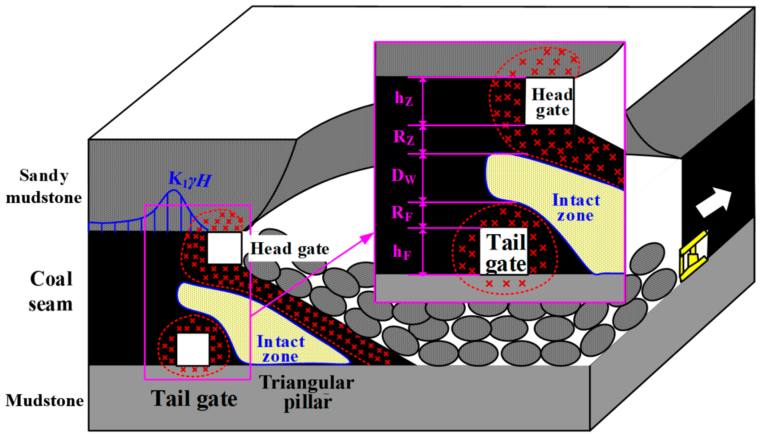
(3) When the zero pillar layout is used, the zone of failure is shown in Figure 4. The stability of the tail gate is the key to the success of the technology. This requires that the triangular coal pillar must be stable, i.e., an intact zone must be within it. The width of the intact zone can be calculated using the equation
where, is the width of the intact zone within the triangular coal pillar; is the thickness of coal seam; is the height of the head gate; is the range of failure of the surrounding rock of the head gate; is the height of the tail gate; is the range of failure of the surrounding rock of the tail gate.
3. Rock Mechanical Properties of Coal in Split-Level Section
Rock mechanical properties in the split-level section are not only determined by the mechanical properties of the intact rock but also influenced by mining. Therefore, the strength of the coal in the split-level section reflects the extent of the influence of mining. The case study coal mine in this paper is Xiegou, at which FMLTCC is being used. The 13# coal seam is being mined, the coal seam average thickness is 14.0 m, and the average dip inclination is 10°. The immediate roof is mainly sandy mudstone. The rock quality is “Good” by the rock mass rating (RMR) system [16]. The floor is mainly mudstone, also classified as “Good” by the RMR system. The panel width is 240 m, the mining height is 3.5 m, and the coal drawing height is 10.5 m. Zero coal pillar is used. The split-level part consists of solid coal and triangular coal parts, as shown in Figure 5.
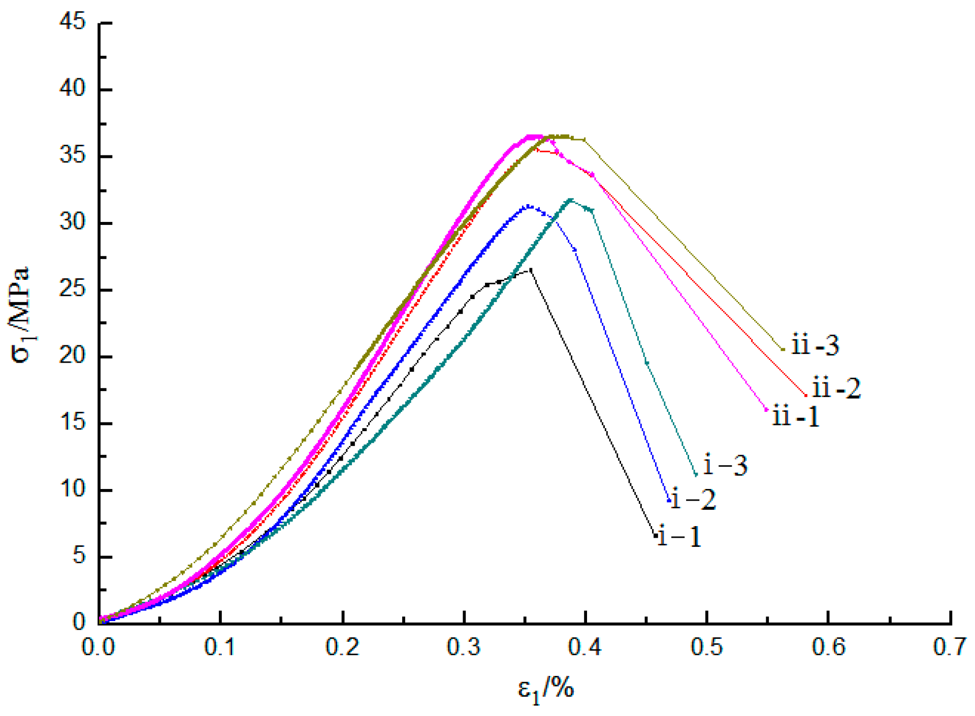
Coal samples were collected from surrounding rock mass of 18103 and 18105 gate road at depth of 0.5 m as shown in Table 1. The samples were processed into standard cylindrical specimens suggested by the International Society for Rock Mechanics and Rock Engineering (ISRM) and tested through the TAW-2000 kN microcomputer and servo-controlled testing machine. The loading rate was 0.1 mm/min. Testing was repeated for three groups of specimens. Average values were then taken and were plotted in Figure 6, and the detailed data are given in Table 1. The comparison of the uniaxial compressive strength (UCS) of coal specimens at different locations is shown in Figure 7.
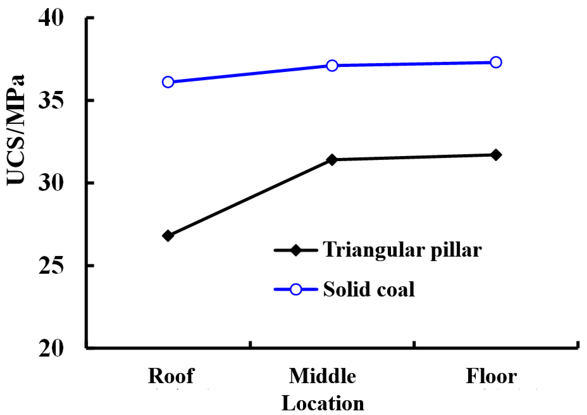
The test result showed that the density and uniaxial compressive strength of coal samples obtained from triangular coal pillar were less than that from solid coal area with a difference of about 5.6–9.3 MPa. The strength of coal at the top was less than the middle and bottom at the triangular coal pillar side. However, the strength of coal at the different locations at the solid coal was similar. This indicates that triangular coal was greatly influenced by mining, microcracks were generated within the surrounding rock mass, and cohesion and internal friction decreased. Therefore, the uniaxial compressive strength as well as the density were both smaller.
According to Mohr–Coulomb criterion, the relationship between UCS, cohesion, and angle of internal friction is [17]
where σc is the uniaxial compressive strength; c is cohesion; φ is the angle of internal friction.
According to elastic–plastic theory [17], the range of the zone of influence is
where r is the equivalent radius of the roadway and H is the cover depth.
It is assumed that the angle of internal friction remains the same, thus
The 18103 head gate is 6.2 m wide and 3.9 m high, the 18105 tail gate is 5.6 m wide and 4.1 m high, the cover depth is 380 m, the unit weight of overburden is 25 kN/m3, the angle of internal friction is 28°, and the ranges of zone of influence for different locations are obtained and listed in Table 2.
4. Simulation of Deformation and Failure at Split-Level Section
A three-dimensional numerical model using FLAC3D software was established according to engineering geological characteristics of the 18103 panel as shown in Figure 8. The dimensions were 591 m in length, 500 m in width, and 150 m in height, to minimize model boundary effects. Appropriate fine zone resolution in the vicinity of the material boundaries and gate roads was used. A uniform stress of 4.5 MPa was applied to the top of the model corresponding to 180 m of overburdened strata by assuming an overburden unit weight of 0.025 MN/m3. The side boundaries were roller constrained, and the bottom boundary was fixed both horizontally and vertically.
The rock mass engineering parameters (Table 3) were developed based on laboratory tests and estimated GSI (Geological Strength Index) values, supplemented by geologic data and field observation.
Figure 9 shows that the triangular coal pillar was mostly in an intact elastic state. Furthermore, the abutment vertical stress distribution shows that the triangular coal pillar suffered lower ground pressure with a stress concentration factor of 1.67. The failure extended downwards and out by the panel along the caving line, and was due to the effect of angle of break, which has been discussed in detail by Wang et al. [18] and Feng et al. [19]. They found that the angle of break (the acute angle created by the coal seam bedding plane and caving line formed by roof strata movement) developed after extraction of a longwall panel; the shear failure in the floor along the panel edge is due to an opposing shear of rock mass on two sides of the caving line. We can also see from the principal stress distribution that the stress trajectories were along the caving line, and the triangular pillar had a stable and low stress environment.
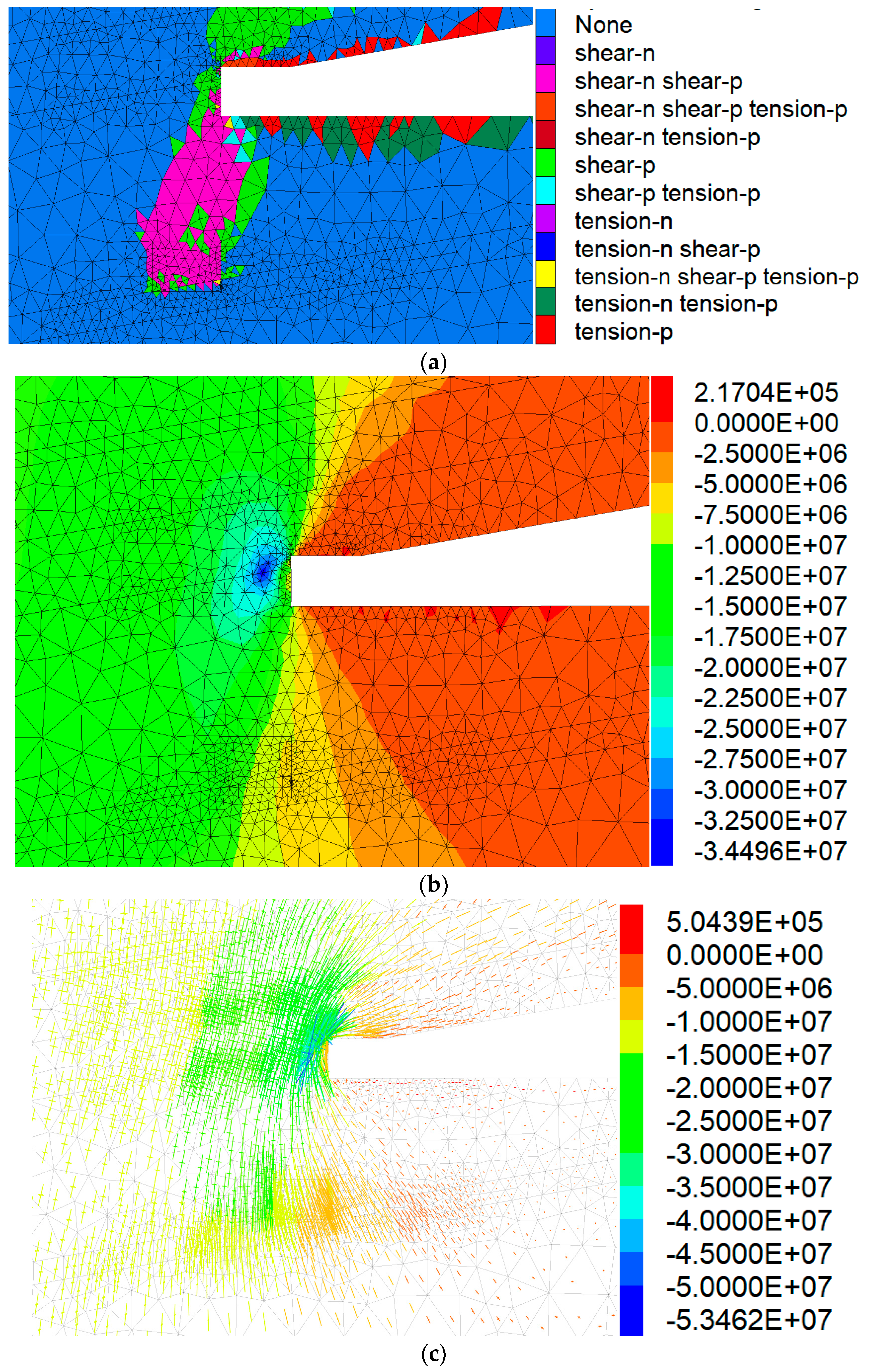
Figure 10 shows that after extraction of the tail gate, the stress distribution and zone of yield hardly changed. The depth of the yield zone on the right rib of the tail gate was around 1 m. The stress on the left rib in the deep rock mass of the tail gate was slightly stressed with a stress concentration factor of 1.64. However, the stress concentration factor for the roof was only 0.07 and that on the right rib was only 1. Therefore, for this layout, the key to support was the left rib, where the stress was higher. Attention should be paid to this since the entry was excavated within the yield zone.
5. Physical Modeling Study
Physical modeling was carried out using plane stress simulation. The geometric scaling factor (the ratio of model size to prototype size) was 1:160 and the density ratio was 1:1.5. The overburden load that was not built was compensated for by using hydraulic jacks on the top. The model materials consisted of aggregate (fine sand) and cement materials (lime and plaster of Paris). The proportions of different constituents in the model materials were tested through trial and error to get the parameters given in Table 4. Strain gauges were embedded into the model materials appropriately to measure strains, and a strain gauge indicator was used to collect strain data. The model dimensions were 4200 mm long, 1500 mm high, and 250 mm thick, as shown in Figure 11.
The key steps and data are shown in Figure 12, Figure 13 and Figure 14. These figures show the roof strata movement and stress distribution.
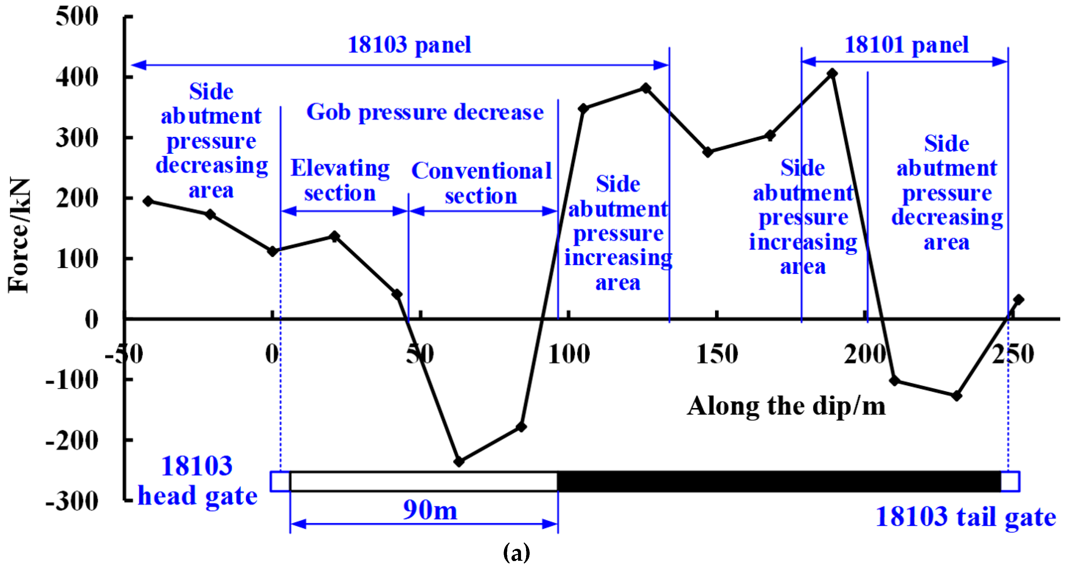
The figures show that when the 90 m of panel was extracted, the broken strata did not reach that high, the side abutment stress decreasing area was about 50 m wide, the stress decreasing area in the gob was about 90 m wide, and the side abutment increasing area was about 40 m. The stress in the elevated section was different from the conventional part of panel, as shown in Figure 14a. This may be due to the height of the extracted coal being different. When the 170 m of panel was extracted, more of the roof strata broke. The side abutment on the left of 18103 head gate increased significantly while the stress around the tail gate hardly changed. Therefore, the tail gate was within the low stress area with little change. The location of the tail gate was reasonable.
6. Conclusions
(1) The split-level gob-side entry is subject to double excavation-induced influence; as well as the abutment pressure, shield reactive force, and gob compression, it requires that there must be an intact zone within the triangular coal pillar to keep the stability of the gob-side entry.
(2) The uniaxial compressive strength of coal from the triangular coal pillar is 26.8–31.7 MPa, while the strength of coal from the solid coal area is 36.1–37.3 MPa, with a difference of 5.6–9.3 MPa. It is concluded that the main reason is the varied degree of mining influence.
(3) Numerical modeling shows that for a zero pillar layout, most triangular coal is in an elastic state, the maximum stress concentration factor of coal is 1.67, and the peak point is in the solid coal side. The depth of plastic zone on the triangular side is only around 1 m, which is conducive to the control of surrounding coal.
(4) The split-level gob-side entry is in the destressed zone with little change of stress before and after its excavation. The location of the split-level gob-side entry is reasonable. SLGE is preferable for ultra-thick coal seams.
Funding
This research was funded by the National Key R&D Program of China (2018YFC0604703) and the research fund of the State Key Laboratory for GeoMechanics and Deep Underground Engineering, CUMTB (SKLGDUEK1828).
Acknowledgments
The author would like to thank reviewers and editors for their kind work.
Conflicts of Interest
The author declares no conflict of interest.
References
- Hou, C.J.; Li, X.H. Stability principle of big and small structures of rock surrounding roadway driven along goaf in fully mechanized top coal caving face. J. China Coal Soc. 2001, 26, 1–7. (In Chinese) [Google Scholar]
- Li, X.H. Numerical Investigation of the Effect of the Location of Critical Rock Block Fracture on Crack Evolution in a Gob-side Filling Wall. Rock Mech. Rock Eng. 2016, 49, 1041–1058. [Google Scholar] [CrossRef]
- Bai, J.B. Study on Stability Principle and Control Technology of Surrounding Rock Along Excavated Roadway. Ph.D. Thesis, China University of Mining and Technology, Xuzhou, China, 2002. (In Chinese). [Google Scholar]
- Su, H.; Bai, J.B.; Yan, S. Study on gob-side entry retaining in fully-mechanized longwall with top-coal caving and its application. Int. J. Min. Sci. Technol. 2015, 25, 503–510. [Google Scholar] [CrossRef]
- Zhang, Z.Z.; Bai, J.B.; Chen, Y.; Yan, S. An innovative approach for gob-side entry retaining in highly gassy fully-mechanized longwall top-coal caving. Int. J. Rock Mech. Min. Sci. 2015, 80, 1–11. [Google Scholar] [CrossRef]
- Li, L.; Bai, J.B.; Wang, X.Y. Rational position and control technique of roadway driving along nextgoaf in fully mechanized top coal caving face. J. China Coal Soc. 2012, 37, 1564–1569. (In Chinese) [Google Scholar]
- Tan, Y.L.; Yu, F.H.; Ning, J.G.; Zhao, T.B. Design and construction of entry retaining wall along a gob-side under hard roof stratum. Int. J. Rock Mech. Min. Sci. 2015, 77, 115–121. [Google Scholar] [CrossRef]
- Li, H.M.; Peng, S.S.; Li, H.G.; Xu, Y.X.; Yuan, R.F.; Yue, S.S.; Li, K. Trial of small gateroad pillar in top coal caving longwall mining of large mining height. Int. J. Min. Sci. Technol. 2016, 26, 139–147. [Google Scholar] [CrossRef]
- Shi, P.W.; Xu, S.D.; Chen, Z.Z. Study on the development law of coal mine pressure along the open roadway in fully-mechanized caving. Ground Press. Strata Control 2004, 1, 32–35. (In Chinese) [Google Scholar]
- Yang, H.Y.; Cao, S.G.; Li, Y.; Sun, C.M.; Guo, P. Soft Roof Failure Mechanism and Supporting Method for Gob-Side Entry Retaining. Minerals 2015, 5, 707–722. [Google Scholar] [CrossRef] [Green Version]
- Zhao, J.L. Whole Seam Longwall Mining with Split-Level Gate roads (LMSG) in Thick Coal Seams. China Patent ZL98100544.6, 18 February 1998. (In Chinese). [Google Scholar]
- Zhang, J.W.; Wang, G.L.; Wang, P. Structure of Overlying Strata in Fully Mechanized Sublevel Caving Faces with Stagger Arrangement and Characteristics of Large O-shaped Circle. J. Shandong Univ. Sci. Technol. 2011, 30, 10–16. (In Chinese) [Google Scholar]
- Wang, P.F.; Zhao, J.L.; Su, Y. An innovative longwall mining technology in Tangshan coal mine, China. Minerals 2017, 7, 14. [Google Scholar]
- Feng, G.R.; Wang, P.F.; Chugh, Y.P. Stability of the Gateroad Next to an Irregular Yield Pillar: A Case Study. Rock Mech. Rock Eng. 2018, 25, 1–20. [Google Scholar]
- Feng, G.R.; Wang, P.F.; Chugh, Y.P.; Zhao, J.L.; Wang, Z.Q. A New Gob-side Entry Layout for Longwall Top Coal Caving. Energies 2018, 11, 1292. [Google Scholar] [CrossRef]
- Bieniawski, Z.T. Engineering Rock Mass Classifications; Wiley: New York, NY, USA, 1989; pp. 5–249. [Google Scholar]
- Brady, B.H.; Brown, E.T. Rock Mechanics: For Underground Mining, 3rd ed.; Springer: Dordrecht, The Netherlands, 2006; p. 106. [Google Scholar]
- Wang, P.F.; Zhao, J.L.; Feng, G.R.; Wang, Z.Q. Interaction between Vertical Stress Distribution within Goaf and Surrounding Rock Mass in Longwall Panel Systems. J. S. Afr. Inst. Min. Metall. 2018, 118, 745–756. [Google Scholar] [CrossRef]
- Feng, G.R.; Wang, P.F. Stress environment of entry driven along gob-side through numerical simulation incorporating the angle of break. Int. J. Min. Sci. Technol. 2019, in press. [Google Scholar]
Figure 1.
Split-level panel forms (cross-section view). (a) Negative coal pillar; (b) Zero coal pillar; (c) Positive coal pillar.
Figure 1.
Split-level panel forms (cross-section view). (a) Negative coal pillar; (b) Zero coal pillar; (c) Positive coal pillar.

Figure 2.
Failure situation after extraction of the head gate.

Figure 3.
Failure situation while the working face is advancing.

Figure 4.
Failure situation after extraction of the tail gate of the next panel.

Figure 5.
Layout with zero pillar at Xiegou mine.

Figure 6.
Stress–strain curves of coal specimens under uniaxial compression.

Figure 7.
Uniaxial compressive strength (UCS) of coal specimens at different locations.

Figure 8.
FLAC3D numerical model.

Figure 9.
Surrounding rock stability with 10.5 m height of stagger arrangement mining. (a) Plastic zone; (b) Abutment vertical stress distribution; (c) Principal stress distribution.
Figure 9.
Surrounding rock stability with 10.5 m height of stagger arrangement mining. (a) Plastic zone; (b) Abutment vertical stress distribution; (c) Principal stress distribution.

Figure 10.
Surrounding rock stability with zero pillar. (a) Plastic zone; (b) Abutment vertical stress distribution; (c) Principal stress distribution.
Figure 10.
Surrounding rock stability with zero pillar. (a) Plastic zone; (b) Abutment vertical stress distribution; (c) Principal stress distribution.

Figure 11.
Physical model.

Figure 12.
90 m of the panel is extracted.

Figure 13.
Extraction is finished.

Figure 14.
Pressure distribution for different extraction lengths of the panel. (a) Pressure distribution when 90 m of the panel is extracted; (b) Pressure distribution when 170 m of the panel is extracted.
Figure 14.
Pressure distribution for different extraction lengths of the panel. (a) Pressure distribution when 90 m of the panel is extracted; (b) Pressure distribution when 170 m of the panel is extracted.


Table 1.
Rock mechanical test results.
| Number | Sample Location | Density (g/cm3) | UCS/MPa | Influence Source |
|---|---|---|---|---|
| i-1 | 18103 head gate roof | 1.31 | 26.8 | Excavation of 18103 head gate Extraction of 18103 panel Excavation of 18105 tail gate |
| i-2 | 18103 head gate rib | 1.35 | 31.4 | |
| i-3 | 18103 head gate floor | 1.33 | 31.7 | |
| ii-1 | Tail gate roof | 1.39 | 36.1 | Excavation of 18103 head gate |
| ii-2 | Tail gate rib | 1.44 | 37.1 | |
| ii-3 | Tail gate floor | 1.41 | 37.3 |
Table 2.
Failure scope of surrounding rock with different UCS.
| Entry | Number | UCS/MPa | Range of Zone of Influence/m |
|---|---|---|---|
| 18105 tail gate | i-1 | 26.8 | 2.622 |
| i-2 | 31.4 | 2.533 | |
| i-3 | 31.7 | 2.528 | |
| 18103 head gate | ii-1 | 36.1 | 2.728 |
| ii-2 | 37.1 | 2.714 | |
| ii-3 | 37.3 | 2.711 |
Table 3.
Rock mass engineering properties used in numerical modeling.
| Lithology | Thickness/m | UCS (MPa) | Density (g/cm3) | Bulk Modulus (GPa) | Shear Modulus (GPa) | Cohesion (MPa) | Tensile Strength (MPa) | Internal Friction Angle (deg) |
|---|---|---|---|---|---|---|---|---|
| Mudstone | 7.81 | 41.8 | 2.52 | 6.2 | 4.5 | 2.1 | 1.6 | 35 |
| 6# coal seam | 1.26 | 30 | 1.43 | 2.7 | 2.1 | 1.5 | 0.9 | 30 |
| Sandstone | 13.64 | 69.8 | 2.72 | 10.7 | 7.4 | 2.7 | 2.2 | 39 |
| 8# coal seam | 4.87 | 30 | 1.43 | 2.7 | 2.1 | 1.5 | 0.9 | 30 |
| Sandy mudstone | 3.39 | 70.1 | 2.76 | 8.2 | 6.5 | 3.1 | 1.9 | 37 |
| Muddy limestone | 7.74 | 53.1 | 2.5 | 8.5 | 6.1 | 2.2 | 1.8 | 38 |
| Mudstone | 12.82 | 41.8 | 2.52 | 6.2 | 4.5 | 2.1 | 1.6 | 35 |
| 10# coal seam | 0.79 | 30 | 1.43 | 2.7 | 2.1 | 1.5 | 0.9 | 30 |
| Muddy limestone | 7.38 | 53.1 | 2.5 | 11.5 | 8.5 | 3.0 | 1.0 | 32 |
| Mudstone | 9.14 | 41.8 | 2.52 | 6.2 | 4.5 | 2.1 | 1.6 | 35 |
| 12# coal seam | 0.88 | 30 | 1.43 | 2.7 | 2.1 | 1.5 | 0.9 | 30 |
| Medium-grained sandstone | 4.76 | 109.53 | 2.72 | 12.2 | 8.5 | 3.9 | 2.7 | 40 |
| Sandy mudstone | 5.22 | 70.1 | 2.76 | 8.2 | 6.5 | 3.1 | 1.9 | 37 |
| 13# coal seam | 14.0 | 30 | 1.41 | 2.7 | 2.1 | 1.5 | 0.9 | 30 |
| Mudstone | 2.08 | 41.8 | 2.52 | 6.2 | 4.5 | 2.1 | 1.6 | 35 |
Table 4.
Parameters of materials for physical modeling.
| No. | Lithology | Thickness of Prototype/m | UCS of Prototype (MPa) | Unit Weight of Prototype (g/cm3) | UCS of the Physical Model (MPa) | Unit Weight of Physical Model (g/cm3) |
|---|---|---|---|---|---|---|
| 1 | Mudstone | 7.81 | 41.8 | 2.52 | 0.17 | 1.68 |
| 2 | 6# coal seam | 1.26 | 30 | 1.43 | 0.13 | 0.95 |
| 3 | Sandstone | 13.64 | 69.8 | 2.72 | 0.29 | 1.81 |
| 4 | 8# coal seam | 4.87 | 30 | 1.43 | 0.13 | 0.95 |
| 5 | Sandy mudstone | 3.39 | 70.1 | 2.76 | 0.29 | 1.84 |
| 6 | Muddy limestone | 7.74 | 53.1 | 2.5 | 0.22 | 1.67 |
| 7 | Mudstone | 12.82 | 41.8 | 2.52 | 0.17 | 1.68 |
| 8 | 10# coal seam | 0.79 | 30 | 1.43 | 0.13 | 0.95 |
| 9 | Muddy limestone | 7.38 | 53.1 | 2.5 | 0.22 | 1.67 |
| 10 | Mudstone | 9.14 | 41.8 | 2.52 | 0.17 | 1.68 |
| 11 | 12# coal seam | 0.88 | 30 | 1.43 | 0.13 | 0.95 |
| 12 | Medium-grained sandstone | 4.76 | 109.53 | 2.72 | 0.46 | 1.81 |
| 13 | Sandy mudstone | 5.22 | 70.1 | 2.76 | 0.29 | 1.67 |
| 14 | 13# coal seam | 14.0 | 30 | 1.41 | 0.13 | 0.97 |
| 15 | Mudstone | 2.08 | 41.8 | 2.52 | 0.17 | 1.68 |
© 2019 by the author. Licensee MDPI, Basel, Switzerland. This article is an open access article distributed under the terms and conditions of the Creative Commons Attribution (CC BY) license (http://creativecommons.org/licenses/by/4.0/).
Share and Cite
MDPI and ACS Style
Zhang, J. Stability of Split-Level Gob-Side Entry in Ultra-Thick Coal Seams: A Case Study at Xiegou Mine. Energies 2019, 12, 628. https://doi.org/10.3390/en12040628
AMA Style
Zhang J. Stability of Split-Level Gob-Side Entry in Ultra-Thick Coal Seams: A Case Study at Xiegou Mine. Energies. 2019; 12(4):628. https://doi.org/10.3390/en12040628
Chicago/Turabian StyleZhang, Junwen. 2019. "Stability of Split-Level Gob-Side Entry in Ultra-Thick Coal Seams: A Case Study at Xiegou Mine" Energies 12, no. 4: 628. https://doi.org/10.3390/en12040628
Note that from the first issue of 2016, this journal uses article numbers instead of page numbers. See further details here.