Optimal Control for Hybrid Energy Storage Electric Vehicle to Achieve Energy Saving Using Dynamic Programming Approach

1
Automotive engineering research institute, Jiangsu University, Zhenjiang 212013, China
2
College of automotive and traffic engineering, Jiangsu University, Zhenjiang 212013, China
*
Author to whom correspondence should be addressed.
Energies 2019, 12(4), 588; https://doi.org/10.3390/en12040588
Submission received: 27 December 2018
/
Revised: 9 February 2019
/
Accepted: 11 February 2019
/
Published: 13 February 2019
(This article belongs to the Special Issue Energy Storage and Management for Electric Vehicles)
Abstract
:In this paper, the efficiency characteristics of battery, super capacitor (SC), direct current (DC)-DC converter and electric motor in a hybrid power system of an electric vehicle (EV) are analyzed. In addition, the optimal efficiency model of the hybrid power system is proposed based on the hybrid power system component’s models. A rule-based strategy is then proposed based on the projection partition of composite power system efficiency, so it has strong adaptive adjustment ability. Additionally. the simulation results under the New European Driving Cycle (NEDC) condition show that the efficiency of rule-based strategy is higher than that of single power system. Furthermore, in order to explore the maximum energy-saving potential of hybrid power electric vehicles, a dynamic programming (DP) optimization method is proposed on the basis of the establishment of the whole hybrid power system, which takes into account various energy consumption factors of the whole system. Compared to the battery-only EV based on simulation results, the hybrid power system controlled by rule-based strategy can decrease energy consumption by 13.4% in line with the NEDC condition, while the power-split strategy derived from the DP approach can reduce energy consumption by 17.6%. The results show that compared with rule-based strategy, the optimized DP strategy has higher system efficiency and lower energy consumption.
1. Introduction
Due to the shortcomings of short life and low power density of power battery, if power battery is used as the sole energy source of electric vehicle (EV), the power and economy of vehicles will be greatly limited [1,2]. The utilization of high-power density super capacitor (SC) into the EV power system and the establishment of a battery-super capacitor hybrid power system can achieve complementary advantages to make up for the lack of power battery [3,4]. Yi Hongming simulated the important modules of the SC-battery hybrid power system in MATLAB/Simulink. The results show that the hybrid power system can exert its high energy density and high-power density characteristics, thus improving the vehicle’s dynamic performance and energy utilization [5]. Xu and Wang combined high-power SC with traditional batteries, and adopted parallel interleaving technology in DC/DC converter, which changed the topology of the hybrid power supply, greatly improving the overall performance of the composite power system. The fuzzy control method is used to manage the energy storage system [6]. Cezar improved the performance of the combined energy storage unit by introducing SC as auxiliary power supply. This paper presents a complete energy storage system model, including a battery, a SC and a rule-based control strategy. When the power required for energy storage is higher than the threshold, the SC is released, which means that the power of the driver needs to be increased for a period of time [7]. Therefore, a SC with battery hybrid power system is proposed in this paper, which is composed of the battery-super-capacitor hybrids, transmission and the electric motor in this research. Specific efficiency characteristics are displayed by each component of the hybrid power system, which is strongly affected by the power demands according to driving conditions and driver’s intentions. EV with battery-super-capacitor hybrids can attain minimum energy consumption through switching different driving modes according to the high efficiency area of the hybrid power system [8].
In addition, the rationality of the energy distribution strategy of the composite power system is also an important factor affecting energy consumption. Special efforts have been devoted to the design and implementation of optimal energy management strategies concerning their importance to urban EV. Essentially, existing approaches may be categorized in rule-based control strategies, optimization and intelligent control strategies [9]. (1) Rule-based methods and analytic methods are usually operation mode dependent. (2) Optimal theory methods can be classified as global optimization and real-time optimization methods, including minimum principle, quadratic programming and dynamic programming (DP) method. (3) Intelligent control methods include neural networks, and model predictive control methods, fuzzy logic, genetic algorithm method, and swarm optimization method [10]. Rule-based methods have difficulty achieving optimal control effect, but they are simple and easily conducted; real-time application of intelligent control methods are limited because of they involve more calculation and are time-consuming [11]. Banvait proposed a rule-based energy management strategy for plug-in hybrid electric vehicle (PHEV), then a PHEV model was built using Advisor software, and the simulation results show that the strategy can significantly reduce fuel consumption [12]. Hemi proposed a rule-based energy management strategy combined with the equivalent consumption minimization strategy (ECMS), which is developed and simulated by using a dynamic model of the vehicle developed in the Matlab/Simulink environment. The simulation results verify the effectiveness of the strategy under various vehicle masses [13]. Previous research about energy management algorithms are concentrated in the field of energy management algorithm based on optimization. DP is a widely-used method that applies search for absolutely optimal controls under a predetermined driving cycle [14]. Optimal power management strategy obtained by DP was employed in parallel hybrid electric vehicle (HEV) to minimize fuel consumption [15]. A finite horizon dynamical optimization problem with constraints of proper energy limits and solved by a DP approach was proposed by Xiaosong Hu, in order to avoid physical damage of the electrical storage system [16]. A driving pattern recognition technique of switching among the control rule employed in the optimal power management strategy for range extended electric vehicle sets extracted from DP results of each representative driving pattern [17]. An optimal solution to the energy management problem in fuel-cell hybrid vehicles with dual storage buffer for fuel economy in a standard driving cycle using multi-dimensional dynamic programming (MDDP) was suggested and turned out to be applicable [18]. An energy management strategy based on stochastic dynamic programming was proposed for a serial hybrid electric tracked vehicle [19]. DP typically focuses on the energy consumed during the driving event as its objective, with the SOC indicating the state of the system, and either the power split ratio or the torque split ratio as the control variable [20]. However, the real-time controller based on DP is effective only for the driving cycle that is used for rule extraction [21]. For the near-optimal rule-based energy split strategy, control rules can also be extracted from the DP results [22]. In summary, rules-based and DP method used in composite power pure electric vehicles, the existing research shows that the main optimization lies in the optimization of motor control and optimized space can be limited; in this paper, the hybrid power system and motor drive system are comprehensively considered, and the optimal efficiency model of the hybrid power system is established to explore the best feasible scheme of energy utilization for pure electric vehicles.
In order to propose a systematic optimal solution for hybrid power system and energy split strategy, high efficiency areas of hybrid power system under single power and hybrid power modes needed to be rationally distributed. Efficiency characteristics analysis of battery, SC, electric motor and DC/DC converter is a vital part of the solution. Based on simulation and experiment methods, the efficiency formulas of the hybrid power system can be summarized under different working conditions, with vehicle acceleration and velocity as independent variables. It is critical to set the status parameters of battery and SC as constraints of optimization problems, because constraints represent the work status of both energy storage units, and work status directly influences the efficiency of the hybrid power system. In this sense, after analyzing the characteristics of each component of the hybrid power system, the efficiency calculation model of the hybrid power system is established. On this basis, a rule-based energy management strategy is proposed, and then the DP method is used to solve the optimization problem of the optimal energy allocation strategy for the hybrid power system of EV.
The structure of the paper is organized as follows: firstly, the materials and methods are provided in Section 2, and the structure and the key components models of hybrid power system in EV are presented in Section 2.1, Section 2.2, Section 2.3 and Section 2.4, which include description of the hybrid power system, battery model, SC model and electric motor; and the rule-based strategy and DP optimization strategy is described in Section 2.5 and Section 2.6. In Section 3, the results and discussions of rule-based energy management strategy and energy allocation optimization strategy based on DP are presented. Finally, conclusions are presented in Section 4.
2. Materials and Methods
2.1. Description of the Hybrid Power System
The vehicle is equipped with a brushless direct current motor (BLDC) connected to a fixed-ratio transmission. BLDC is powered by battery and SC. The bidirectional DC/DC converter is used to interface the SC with the BLDC. Energy management controller plays the role of power split in the hybrid power system. The architecture of the hybrid power system is as shown in Figure 1. The main parameters of the EV used in this study are listed in Table 1.
2.2. Battery Model
Lithium-ion batteries are preferred in EV applications owing to their high voltage, good safety property, and long cycling life [23]. The main parameters of the Lithium-ion battery used in this study are given in Table 2.
Rint model is commonly used in describing the characteristics of the lithium battery, which is applied because of its simplicity and little inaccuracy. The battery behavior is represented by the Rint model depicted in Figure 2a.
The parameter data of variables is obtained through battery characteristics experiments, and the calculation results of the battery module internal resistance are shown in Table 3. According to the calculation results of the internal resistance of the battery module in Table 3, the relationship between battery SOC and internal resistance can be obtained by polynomial fitting under MATLAB environment (The MathWorks, Inc, Natick, MA, USA), and 6 times polynomial is obtained, such as Equation (1).
where represents the SOC value of the battery, (mΩ) is the internal resistance of the battery. The fitting curve is shown in Figure 3, and a conclusion can be drawn through analyzing the data that the resistance appears smaller when the SOC was between 0.3 and 0.9. Hence, 0.3 to 0.9 is a high-efficiency working region for battery which will be used as boundaries of constraints.
The following two formulas demonstrate the mathematical character of battery based on the equivalent circuit model above.
where E is the electromotive force; Ub is the battery terminal voltage; Ib represents the battery current load; R0 represents internal resistance; is the power loss.
2.3. SC Model
The basic parameters of the SC modules used in this paper are listed in Table 4. The transmission line model shown in Figure 2b was adopted to represent the characteristics of the SC with its simplicity and sufficient accuracy. The series/parallel numbers SSC/PSC of the SC module within the SC pack is 40/9 in this study. SC working states are divided into 2 states in this paper beforehand, as shown in Figure 4. When the terminal voltage of SC is between UH and Vsc_max, SC single drive is the priority selection; when the terminal voltage of SC is between UH and Vsc_min, the driving modes are decided by the system efficiency.
The series resistance (Res) is relatively steady, and the parallel resistance (Rep) demonstrates the current leakage, which is small enough to be neglected. Hence, the approximate power wastage of SC is mainly caused by Res. The mathematical model of SC is expressed by the equations below.
where USC represents the terminal voltage of SC; ISC is the outputting current; UC is the actual voltage of the capacitor in the SC; Ip is the leakage current.
2.4. Electric Motor
The basic parameters of the motor used are listed in Table 5. The motor output power was evaluated through testing the rotor speed and torque, which could be used to distinguish the efficiency region and divide the power split mode, meanwhile the electric motor efficiency under different torque and rotor speed could be obtained. An efficiency map of the motor is presented in Figure 5. The top blue line represents the characteristics curve of the motor: the first half is constant torque phase, and the latter part is constant power stage.
2.5. Rule-Based Energy Management Strategy
The aim of optimal control strategy is to maximize the efficiency of the hybrid power system, the efficiency of which is expressed as follows.
where Preq is the power requirement of hybrid power system, Pw-bat is the power dissipation of battery. Pw-SC is the power dissipation of SC. Pw-DC represents the power dissipation of DC/DC converter. Pw-MOT represents the power loss in electric motor.
The rolling resistance, the air resistance, the ramp resistance and the acceleration resistance are mainly used in the process of vehicle driving, and the force equation is shown in Equation (7):
where Ff is rolling resistance, Fw is air resistance, Fi is ramp resistance, and Fj is acceleration resistance. The specific expressions of each force are expressed as Equation (8), and the calculation of demand power is as shown in Equation (9).
where m is the EV mass, g is the gravitational acceleration, f is the rolling resistance coefficient, v is the EV velocity, a is the EV acceleration, i is the climbing angle, CD is the air drag coefficient, A is the front area, δ is the generalized inertia coefficient, ηT is the transmission efficiency. All the variables are formulated as the equations below:
where ηDC is the efficiency of the DC/DC converter.
According to the above efficiency calculation mathematical model and the characteristics analysis of each component of the composite power system, the efficiency calculation model is built in Simulink, as shown in Figure 6. Vehicle speed and acceleration as the input of the model can be converted into the motor output speed and torque through the conversion module, thus the required driving power of the vehicle can be calculated through the demand power module. Then it is transferred to the logic module, which distributes the direct current bus power to the battery module and the SC module according to the different driving modes of the vehicle. The DC/DC converter is included in the SC module. Finally, the efficiency of the system can be calculated by summing up the power loss of battery, SC, DC/DC converter and motor to the efficiency calculation module.
System efficiency varies significantly under different conditions concerning different battery and SC states. Depending on the working states of battery and SC, the hybrid power system is classified into four conditions. Based on the relevant tests on battery, a relative low resistance region (SOCb <= SOC <= SOCt) was obtained as mentioned above, and for SC, high and low terminal voltage work region was determined by a middle voltage line Um.
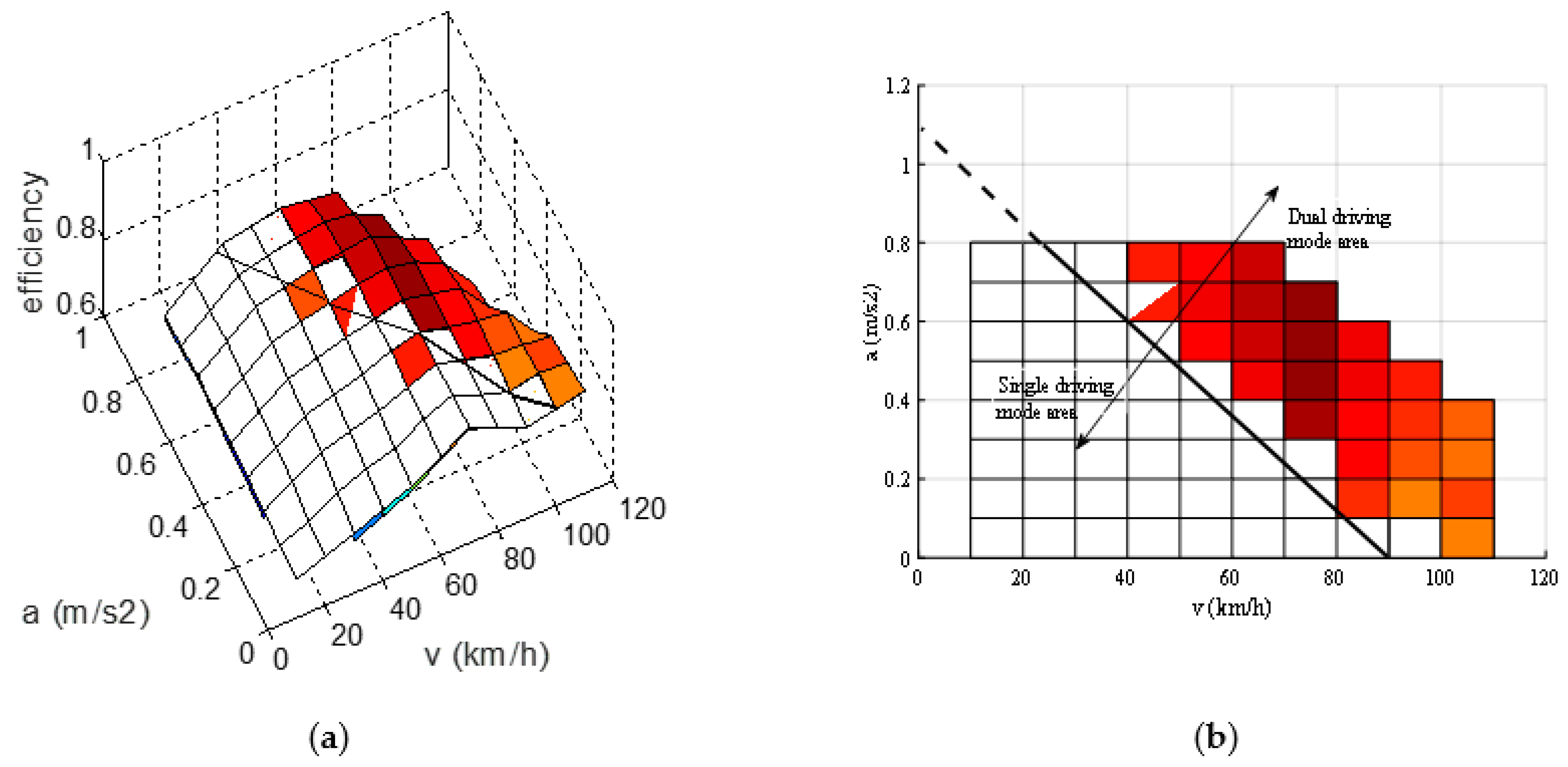
(1) Condition 1: Battery stays in high efficiency region, and the initial terminal voltage of SC stays in high value. Adjusting the power limit of battery, and a maximum efficiency value under each couple of vehicle velocity and acceleration is seek out. The simulation results of the efficiency model of the power system under Condition 1 are depicted in Figure 7.
As the Figure 7 shows (similar to Figure 8, Figure 9 and Figure 10), the white mesh stands for the efficiency in single driving mode; the colorful one stands for the dual driving mode; meanwhile the switching rule of single driving mode and dual driving mode under Condition 1 can be summarized. It can be seen from Figure 7a (similar to Figure 8a, Figure 9a and Figure 10a) that the efficiency of single driving mode is higher than that of dual driving mode when the speed and acceleration are smaller, and the power system should work in single driving mode at this time. With the increase of the vehicle speed and acceleration, the efficiency of dual driving mode increases slowly and is larger than that of single driving mode, and the power system should work in dual driving mode at this time. In order to accurately find out the switching rules of single driving mode and dual driving mode in power system, the three-dimensional surface graph shown in Figure 7a (similar to Figure 8a, Figure 9a and Figure 10a) is projected to the v-a plane, and the efficiency differentiation curve of single driving mode and dual driving mode can be obtained in Figure 7b (similar to Figure 8b, Figure 9b and Figure 10b). The dividing line between white grid and color grid is the switching rule of single driving mode and dual driving mode: when the speed and acceleration are located at the lower left of the dividing line, the efficiency of single driving mode is higher and the power system should switch to single driving mode; when the speed and acceleration are at the upper right of the dividing line, the efficiency of dual driving mode is higher and the power system switches to dual driving mode.
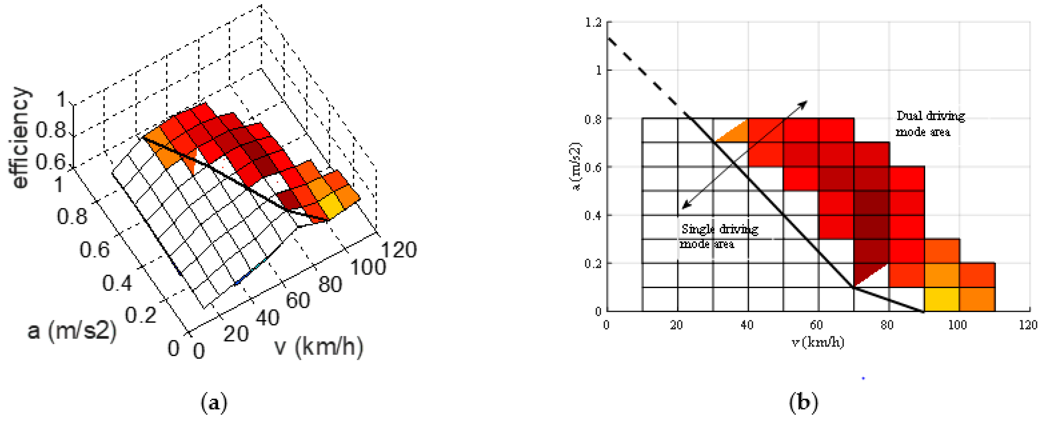
(2) Condition 2: Battery is in lower efficiency region, and SC is in high voltage. The comparison and switching rule are depicted in Figure 8, and the switching rule of single driving mode and dual driving mode under Condition 2 can be summarized according to the explain of switching rules under Condition 1.
(3) Condition 3: Battery stays in high-efficiency region, while SC keeps in low voltage. The comparison and switching rule under Condition 3 can be seen in Figure 9. The switching rule of single driving mode and dual driving mode can be summarized similarly according to the explanation of switching rules under Condition 1.
(4) Condition 4: Both battery and SC stay in low-efficiency region. The simulation results of the power system efficiency model are depicted in Figure 10. The switching rule of single driving mode and dual driving mode under Condition 4 can be obtained similarly according to the explain of switching rules under Condition 1.
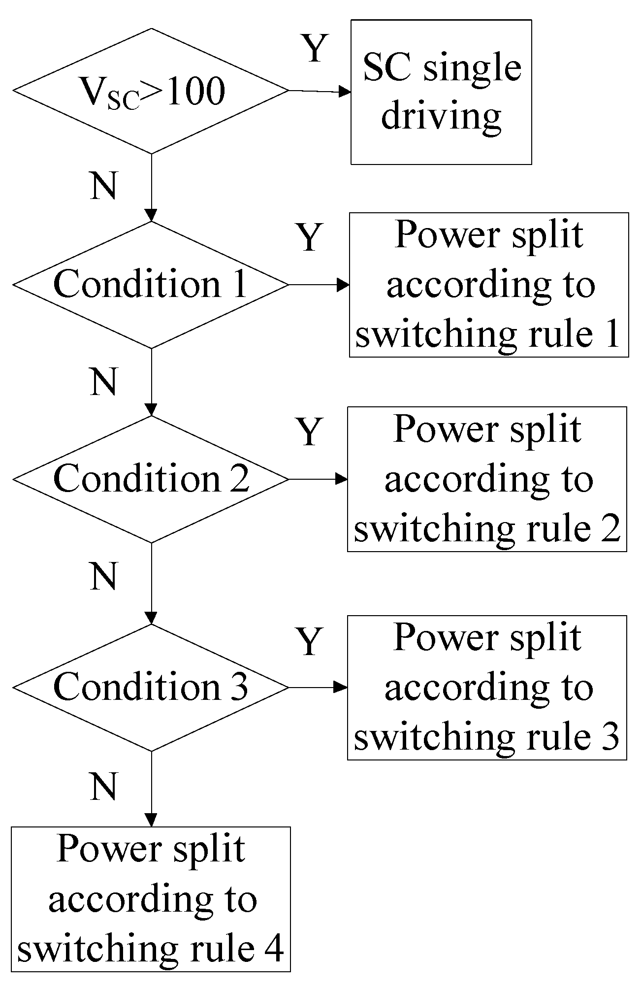
Based on the switching rule of single driving mode and dual driving mode under four different conditions, the schematic flow-chart of the rule-based strategy can be achieved, as shown in Figure 11. It can be seen from the Figure 11 that when the SC terminal voltage is higher than 100, the power system adopts single driving mode. When the terminal voltage of the SC is less than 100, the power distribution of the SC and the battery is determined according to the switching rules under different conditions.
2.6. Energy Management Optimal Strategy Derived from DP Approach
The rule-based strategy is proposed on the basis of power source state and efficiency, and the strategy is empirical, but it cannot achieve the best efficiency optimization effect.
The DP algorithm will be utilized to solve the optimal problem in this section, which is a famous principal of optimization which transfers multistage decision problem to single stage, and solves each problem with the relations between different stages. The recursion equation below plays an essential role in the DP sequential algorithm.
where xk is the state of the kth stage, the decision variable uk is the decision of the state at xk+1, the state transition equation is xk+1 = Tk(xk,uk), the set of allowed decision of k phase is denoted as Dk(xk), vk(xk+1,uk) is as an indicator function.
The DP algorithm aims at minimizing the energy loss of the hybrid power system at every moment under cyclic conditions, so as to achieve the optimization of vehicle efficiency and extend the driving distance. In this paper, the optimal control strategy of energy allocation based on DP algorithm takes the output power of the SC (PSC(t)) as the decision variable of global optimization, and time series as the stage sequence with the interval of 1 s. The SOC of the power battery (SOCb) and the terminal voltage of the SC (VSC) are the state variables of global optimization. The expression is as follows:
The DP optimization process of the energy allocation of the hybrid power system can be expressed as: (1) dividing the search for the minimum energy consumption path of the hybrid power system into several time series at a time interval of 1 s; (2) searching for the optimal decision variable u(t) during the transition from the initial state x(0) to the final state x(t) according to the vehicle power demand at each time; (3) making the hybrid power system achieve smaller energy loss. Therefore, the objective function of DP optimization for energy allocation of composite power system is as follows:
In the above formula, fw(x(t),u(t),t) is the energy loss of the hybrid power system at t time.
According to the above analysis, the cycle condition is divided into N stages in this paper, and the step size between each stage is ∆t (1 s in this paper). Therefore, the discrete global cost function of the hybrid power system is as follows:
The transfer function of the hybrid power system is as follows in this paper:
where ηb(k) is the charging and discharging efficiency of battery, I(k) is the current of battery, Cini is the initial capacity of battery, CSC is the rated capacity of SC.
At the same time, the constraints that should be met are as follows:
where Pr_max is the vehicle maximum demand power, Ib_max is the battery maximum output current, ISC_max is the maximum current of SC.
According to the basic principles and basic equations of the above DP method, the objective function recursive equation of the hybrid power system at any k time can be expressed as:
The DP algorithm adopted in this paper takes the SC terminal voltage of as the initial state variable and discretizes it into 140 states from 0.5VSC,max to VSC,max, as shown in Figure 12. The DP algorithm first carries on the reverse calculation. After the SOC of the battery and the terminal voltage of the SC are given, the optimal decision results of each stage are obtained by the reverse calculation according to the terminal conditions k = kmax. Taking the decision variables of k time u(k), ui(k) as an example, the state of k+1 time x(k+1), xi(k+1) can be obtained according to the system state variables of k-time. Because x(k+1), xi(k+1) is not necessarily the state value at k + 1 time, the energy loss of composite power system corresponding to state x(k+1), xi(k+1) is obtained by interpolation method. The energy loss value of the composite power system with state variables u(k), ui(k) at k time is f(k), fi(k). The output power of the SC corresponding to the smaller one is taken as the optimal decision variable in this stage. All other stages are the same until all stages are reversed. At the end of the reverse recursion, the forward calculation is needed, and the optimal decision variables at each time are obtained by interpolation calculation based on the results of the reverse operation as known variables.
3. Results and Discussion
3.1. The Results of Rule-based Strategy
According to GB/T 18386-2005 Electric vehicles—Energy consumption and range—Test procedures [24], the New European Driving Cycle (NEDC) is utilized to verify the rule-based strategy proposed in the paper. As shown in Figure 13, period ① is urban driving cycle, and period ③ belongs to period ①, which represents the basic urban driving cycle, and period ② means suburban driving cycle.
It can be seen from Figure 13 that the whole cycle is composed of conditions such as parking, driving and braking. Concerning optimal control during driving period is the main aim of this paper, the power loss during parking can be neglected, thus the system efficiency is equivalent to 95% under parking conditions. Based on previous research results [25], the recovery of regenerative braking can be assumed to reach 20%.
The hybrid power system can enter the dual driving mode with higher efficiency in time and reasonably, so the efficiency of the power system will be higher theoretically. In order to verify the advantages of the system efficiency under the rule-based strategy, the NEDC cycle condition is still used as input to observe the change of the efficiency of the power system, as shown in Figure 14. The battery SOC is set to 0.95 and the initial terminal voltage of the SC is set to 108 V when simulating.
As shown in Figure 14, the power system efficiency of rule-based strategy in driving and braking process is higher than that of the single power mode. It can be seen from Figure 14b that the power system efficiency is hardly improved in the case of a small power demand in an urban cycle condition; however, the efficiency of the hybrid power system is improved to a certain extent because it can enter the dual driving mode in time in the case of high power demand. Under braking process, the power system enters the regenerative braking state, and since the single-cell prototype does not have the regenerative braking function, so the efficiency of hybrid power system is higher in braking process. From Figure 14c, it can be observed that the system efficiency of dual driving mode is higher at the time because the vehicle speed in suburban cycle condition is higher. If the SC terminal voltage is above the median, the hybrid power system will be switched to dual driving mode in time to improve the efficiency of power system. Therefore, the system has greater efficiency improvement under the condition of higher power demand, such as suburban cycle condition.
As shown in Figure 15a, rule-based strategy can enter dual driving mode timely, therefore, battery current of rule-based strategy is smaller than battery-only mode. However, rule-based strategy cannot enter dual driving mode under suburban driving condition due to low SC voltage, which can be solved through increasing SC usage, but which will bring cost increase. Furthermore, as shown in Figure 15b, rule-based strategy enters into SC single driving mode concerning high SC voltage and small power demand at about 20s.
3.2. The Results of DP Strategy
Compared with rule-based energy management control strategy, the effectiveness of the proposed energy optimization strategy based on DP algorithm is verified. The initial SOC was set to 0.95, and the initial SC terminal voltage was 108 V. The main program of the DP algorithm was then run; power system efficiency comparison of DP and rule-based strategy is shown in Figure 16. Compared with rule-based control strategy, the energy optimization control strategy based on DP algorithm has more efficiency optimization space. Figure 16b is a partial enlarged view of the system efficiency of an urban cycle, as shown in Figure 16b, the power system efficiency of DP approach is higher than rule-based strategy as a whole. Besides, Figure 16c is a partial enlarged view of the system efficiency of a suburban cycle, as shown in Figure 16c, concerning the SC is of sufficient electricity, there is a magnificent efficiency increase during the first driving process.
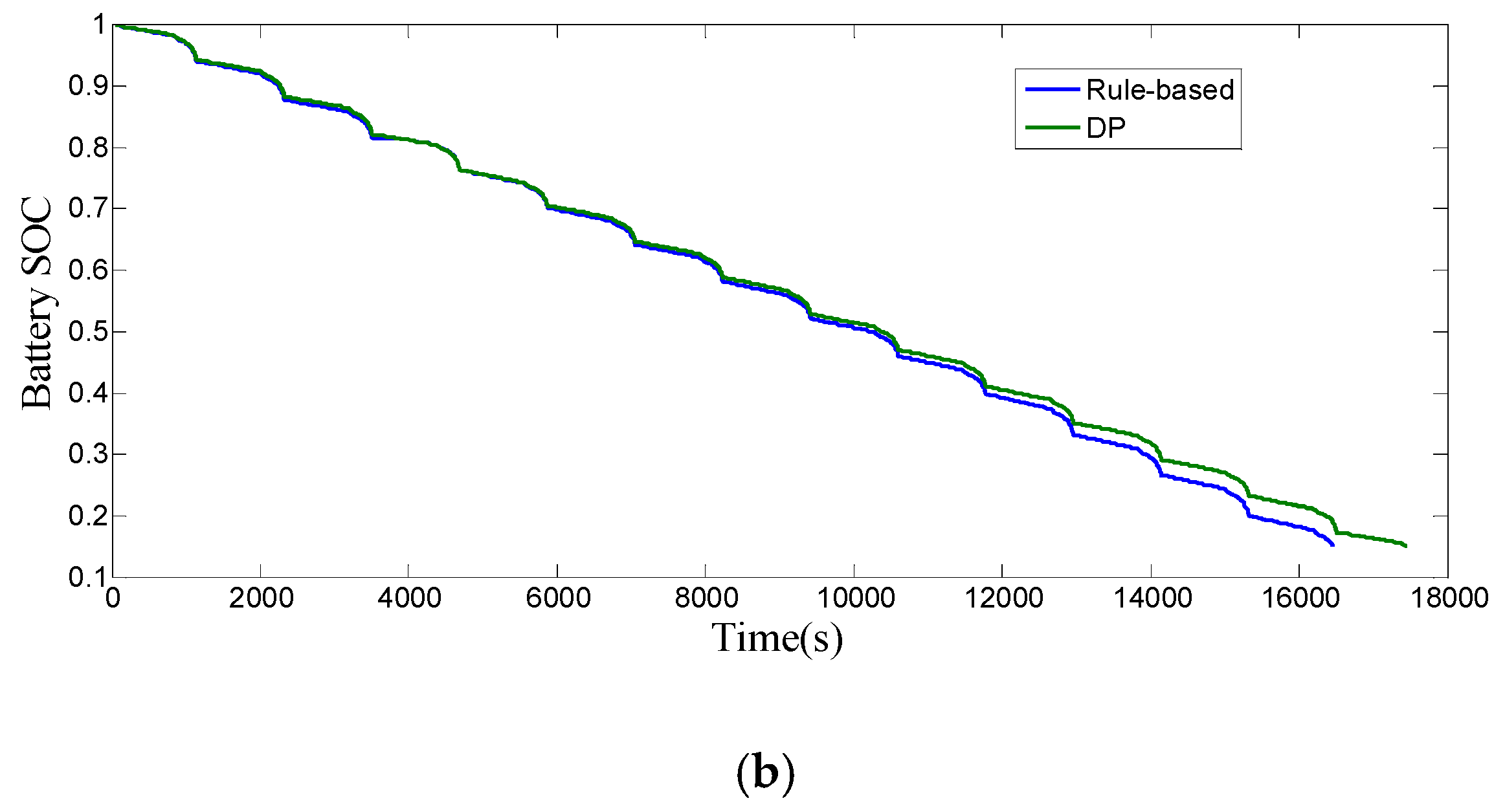
In order to verify the advantages and disadvantages of the two strategies proposed, the initial SOC of the battery is set to 1 and the voltage of the SC is set to 108 V under the NEDC condition and the actual road driving cycle respectively, and the simulation model is set to circulate until the SOC of the battery is reduced to 0.15. Among them, the whole course of the NEDC condition is 11.022 km, and the whole course of the actual road driving cycle is 11.655 km. The SOC change of battery under single NEDC condition is shown in Figure 17a, the SOC change of battery (1–0.15) under multiple NEDC conditions is shown in Figure 17b; and the SOC change of battery under single actual condition is shown in Figure 18a, and the SOC change of battery (1–0.15) under multiple actual conditions is shown in Figure 18b. The speed in Figure 18a is collected from a real vehicle on the campus road surface, which is called the actual road driving cycle. It can be seen from Figure 17 and Figure 18 that compared with the rule-based energy management strategy, the battery SOC of the energy allocation optimization strategy based on the DP algorithm reduces more slowly. That is to say, the energy allocation optimization strategy based on the dynamic programming algorithm is more economical.
Table 6 shows the different strategies comparison of driving range and energy consumption under NEDC condition. It can be seen from Table 6 that compared with the rule-based energy management strategy, the energy optimization allocation strategy based on the DP algorithm has a longer driving range and a lower energy consumption. Compared to the battery-only EV based on simulation results, the hybrid power system controlled by rule-based strategy can decrease 13.4% of the energy consumption along the NEDC condition, while the power split strategy derived from DP approach can reduce by 17.6%. The results verify the effectiveness of the DP algorithm optimization strategy.
4. Conclusions
Based on an optimal efficiency model, a rule-based energy management strategy is proposed, which is based on the projection partition of composite power system efficiency, so it has strong adaptive adjustment ability. In order to explore the maximum energy-saving potential of hybrid power electric vehicles, the DP optimization method is proposed on the basis of the establishment of the whole hybrid power system, which takes into account various energy-consumption factors of the whole system.
System efficiency varies significantly under different conditions due to different battery and SC states. Depending on the working states of battery and SC, the hybrid power system is classified into four conditions in this paper, and the switching rule of single driving mode and dual driving mode under four different conditions are gained. Rule-based strategy is proposed on the basis of the above contents, which can be easily implemented and prominently improves the system efficiency. Compared with the battery-only system, the rule-based energy management strategy has higher power system efficiency, and power system controlled by the proposed rule-based strategy can reduce 13.4% of the energy consumption along NEDC. Meanwhile the effectiveness of the hybrid power system and the availability of the proposed rule-based strategy are validated.
While the rule-based strategy is empirical, it cannot achieve the best efficiency optimization effect. The DP algorithm is utilized to solve the optimal problem. Compared with the rule-based strategy based on simulation results, power system controlled by the strategy deriving from DP approach can reduce 4.8% of the energy consumption along NEDC. Compared to the battery-only EV based on simulation results, the hybrid power system controlled by the power split strategy derived from DP approach can reduce by 17.6%. As a result, the availability of the strategy deriving from DP approach is validated. The results show that compared with rule-based strategy, the optimized DP strategy has higher system efficiency and lower energy consumption.
Author Contributions
Conceptualization, L.C.(Long Chen) and L.C.(Liao Chen); Methodology, C.P.; Software, Y.L.; Validation, C.P., Y.L. and Liao Chen; Formal Analysis, Y.L.; Investigation, L.C.(Long Chen); Resources, L.C.(Long Chen); Data Curation, C.P. and Y.L.; Writing—Original Draft Preparation, C.P. and Y.L.; Writing—Review & Editing, C.P. and Y.L.; Visualization, L.C.(Liao Chen); Supervision, L.C.(Long Chen); Project Administration, C.P.; Funding Acquisition, C.P. and L.C.(Long Chen).
Funding
This research was funded by the National Natural Science Foundation of China, grant number [51105178 and 51707084], and funded by the Natural Science Foundation of Jiangsu Province, grant number [BK20171300 and BK20160529]. This research was also supported by the China Postdoctoral Science Foundation, grant number [2016M591775].
Conflicts of Interest
The authors declare no conflict of interest to the paper. The funders had no role in the design of the study; in the collection, analysis, or interpretation of data; in the writing of the manuscript, and in the decision to publish the results.
References
- Zhou, M.; Wei, L.; Wen, J. The Parameters Matching and Simulation of Pure Electric Vehicle Composite Power Supply Based on CRUISE. Appl. Mech. Mater. 2014, 602, 2836–2839. [Google Scholar] [CrossRef]
- Griffo, A.; Wang, J. Modeling and Stability Analysis of Hybrid Power Systems for the More Electric Aircraft. Electr. Power Syst. Res. 2012, 82, 59–67. [Google Scholar] [CrossRef]
- Salah, I.B.; Bayoudhi, B.; Diallo, D. EV energy management strategy based on a single converter fed by a hybrid battery/supercapacitor power source. In Proceedings of the IEEE International Conference on Green Energy (ICGE), Sfax, Tunisia, 25 March 2014; pp. 246–250. [Google Scholar]
- Mastragostino, M.; Soavi, F. Strategies for high-Performance supercapacitors for HEV. J. Power Sources. 2007, 174, 89–93. [Google Scholar] [CrossRef]
- Yi, H.; Ma, F. Simulation Study of Compound Power Supply System for Electric Vehicles. Power World 2013, 1, 30–33. [Google Scholar]
- Xu, R.; Wang, Y. Simulation of composite electric power for electric vehicles. In Proceedings of the IEEE International Conference on Mechatronics and Automation (ICMA), Takamatsu, Kagawa, Japan, 6–9 August 2017; pp. 967–972. [Google Scholar]
- Cezar, B.; Onea, A. A rule-based energy management strategy for parallel hybrid vehicles with supercapacitors. In Proceedings of the International Conference on System Theory, Control and Computing (ICSTCC), Sinaia, Romania, 14–16 October 2011; pp. 1–6. [Google Scholar]
- Shi, Q.; Zhang, C.; Cui, N. Optimal Control of Energy Management Problems for a New Dual Energy Source Pure Electric Vehicle. Trans. China Electrotechnical Soc. 2008, 23, 137–142. [Google Scholar]
- Trovão, J.P.; Antunes, C.H. A comparative analysis of meta-heuristic methods for power management of a dual energy storage system for electric vehicles. Energy Convers. Manage. 2015, 95, 281–296. [Google Scholar] [CrossRef]
- Chen, Z.; Mi, C.C.; Xiong, R.; Xu, J.; You, C. Energy management of a power-split plug-in hybrid electric vehicle based on genetic algorithm and quadratic programming. J. Power Sources 2014, 248, 416–426. [Google Scholar] [CrossRef] [Green Version]
- Padmarajan, B.V.; Mcgordon, A.; Jennings, P.A. Blended Rule-Based Energy Management for PHEV: System Structure and Strategy. IEEE Trans. Veh. Technol. 2016, 65, 8757–8762. [Google Scholar] [CrossRef]
- Banvait, H.; Anwar, S.; Chen, Y. A rule-based energy management strategy for plug-in hybrid electric vehicle (PHEV). In Proceedings of the American Control Conference, St. Louis, MO, USA, 10–12 June 2009; pp. 3938–3943. [Google Scholar]
- Hemi, H.; Ghouili, J.; Cheriti, A. A real time energy management for electrical vehicle using combination of rule-based and ECMS. In Proceedings of the IEEE Electrical Power and Energy Conference (EPEC), Halifax, NS, Canada, 21–23 August 2013; pp. 1–6. [Google Scholar]
- Hung, Y.-H.; Wu, C.-H. An integrated optimization approach for a hybrid energy system in electric vehicles. Appl. Energy 2012, 98, 479–490. [Google Scholar] [CrossRef]
- Hu, X.; Johannesson, L.; Murgovski, N.; Egardt, B. Longevity-conscious dimensioning and power management of the hybrid energy storage system in a fuel cell hybrid electric bus. Appl. Energy 2015, 137, 913–924. [Google Scholar] [CrossRef]
- Laura, V.P.; Guillermo, R.B.; Diego, M.; Guillermo, O.G. Optimization of power management in an hybrid electric vehicle using dynamic programming. Math. Comput. Simul. 2006, 73, 244–254. [Google Scholar]
- Chen, B.-C.; Wu, Y.-Y.; Tsai, H.-C. Design and analysis of power management strategy for range extended electric vehicle using dynamic programming. Appl. Energy 2014, 113, 1764–1774. [Google Scholar] [CrossRef]
- Ansarey, M.; Panahi, M.S.; Ziarati, H.; Mahjoob, M. Optimal energy management in a dual-storage fuel-cell hybrid vehicle using multi-dimensional dynamic programming. J. Power Sources 2014, 250, 359–371. [Google Scholar] [CrossRef]
- Zou, Y.; Chen, R.; Hou, S.; Hu, X. Energy Management Strategy for Hybrid Electric Tracked Vehicle Based on Stochastic Dynamic Programming. J. Mech. Eng. 2012, 48, 91–96. [Google Scholar] [CrossRef]
- Hou, C.; Ouyang, M.; Xu, L.; Wang, H. Approximate Pontryagin’s minimum principle applied to the energy management of plug-in hybrid electric vehicles. Appl. Energy 2014, 115, 174–189. [Google Scholar] [CrossRef]
- Kim, N.; Cha, S.; Peng, H. Optimal Control of Hybrid Electric Vehicles Based on Pontryagin’s Minimum Principle. IEEE Trans. Control Syst. Technol. 2011, 19, 1279–1287. [Google Scholar]
- Song, Z.; Hofmann, H.; Li, J.; Han, X.; Ouyang, M. Optimization for a hybrid energy storage system in electric vehicles using dynamic programming approach. Appl. Energy 2015, 139, 151–162. [Google Scholar] [CrossRef]
- Xu, L.; Ouyang, M.; Li, J.; Yang, F.; Lu, L.; Hua, J. Optimal sizing of plug-in fuel cell electric vehicles using models of vehicle performance and system cost. Appl. Energy 2013, 103, 477–487. [Google Scholar] [CrossRef]
- Bai, Z.; Cao, L.; Yang, J. Study on the Performance Evaluation Method of Power Batteries for Pure Electric Vehicles. J. Hunan Univ.: Nat. Sci. Ed. 2006, 33, 48–51. [Google Scholar]
- Pan, C.; Chen, L.; Chen, L.; Huang, C.; Xie, M. Research on energy management of dual energy storage system based on the simulation of urban driving schedules. Int. J. Electr. Power Energy Syst. 2013, 44, 37–42. [Google Scholar] [CrossRef]
Figure 1.
Architecture of the hybrid power system.

Figure 2.
Simplified circuit models of battery and super capacitor (SC). (a) Rint model of the battery; (b) Transmission line model of SC.
Figure 2.
Simplified circuit models of battery and super capacitor (SC). (a) Rint model of the battery; (b) Transmission line model of SC.

Figure 3.
Change curve of internal resistance of battery discharge.

Figure 4.
Division of the SC working states.

Figure 5.
Efficiency map of the electric motor.

Figure 6.
Efficiency model of power system.

Figure 7.
Efficiency comparison and switching rule under Condition 1. (a) Efficiency comparison under Condition 1; (b) Switching rule under Condition 1.
Figure 7.
Efficiency comparison and switching rule under Condition 1. (a) Efficiency comparison under Condition 1; (b) Switching rule under Condition 1.

Figure 8.
Efficiency comparison and switching rule under Condition 2. (a) Efficiency comparison under Condition 2; (b) Switching rule under Condition 2.
Figure 8.
Efficiency comparison and switching rule under Condition 2. (a) Efficiency comparison under Condition 2; (b) Switching rule under Condition 2.

Figure 9.
Efficiency comparison and switching rule under Condition 3. (a) Efficiency comparison under Condition 3; (b) Switching rule under Condition 3.
Figure 9.
Efficiency comparison and switching rule under Condition 3. (a) Efficiency comparison under Condition 3; (b) Switching rule under Condition 3.

Figure 10.
Efficiency comparison and switching rule under Condition 4. (a) Efficiency comparison under Condition 4; (b) Switching rule under Condition 4.
Figure 10.
Efficiency comparison and switching rule under Condition 4. (a) Efficiency comparison under Condition 4; (b) Switching rule under Condition 4.

Figure 11.
The flow-chart of the rule-based strategy.

Figure 12.
Dynamic programming (DP) approach flowchart.

Figure 13.
The New European Driving Cycle.

Figure 14.
Comparison of power system efficiency along NEDC. (a) Power system efficiency along New European Driving Cycle (NEDC); (b) Power system efficiency along an urban driving cycle; (c) Power system efficiency along a suburban driving cycle.
Figure 14.
Comparison of power system efficiency along NEDC. (a) Power system efficiency along New European Driving Cycle (NEDC); (b) Power system efficiency along an urban driving cycle; (c) Power system efficiency along a suburban driving cycle.

Figure 15.
Battery current along NEDC. (a) Battery current along NEDC; (b) Battery current along an urban driving cycle.
Figure 15.
Battery current along NEDC. (a) Battery current along NEDC; (b) Battery current along an urban driving cycle.

Figure 16.
Power system efficiency comparison of DP and rule-based strategy. (a) NEDC driving cycle; (b) Urban driving cycle; (c) Suburban driving cycle.
Figure 16.
Power system efficiency comparison of DP and rule-based strategy. (a) NEDC driving cycle; (b) Urban driving cycle; (c) Suburban driving cycle.


Figure 17.
SOC change of battery under NEDC condition. (a) SOC change of battery under single NEDC condition; (b) SOC change of battery under multiple NEDC condition.
Figure 17.
SOC change of battery under NEDC condition. (a) SOC change of battery under single NEDC condition; (b) SOC change of battery under multiple NEDC condition.


Figure 18.
SOC change of battery under actual road driving cycle. (a) SOC change of battery under single actual road driving cycle; (b) SOC change of battery under multiple actual road driving cycle.
Figure 18.
SOC change of battery under actual road driving cycle. (a) SOC change of battery under single actual road driving cycle; (b) SOC change of battery under multiple actual road driving cycle.


Table 1.
Basic parameters of the electric vehicle (EV).
| Parameter | Value |
|---|---|
| m, Vehicle mass (kg) | 1360 |
| R, Wheel radius (m) | 0.277 |
| CD, Air drag coefficient | 0.35 |
| A, Front area (m2) | 2.3 |
| ρ, Air density (kg/m3) | 1.29 |
| i0, Transmission ratio | 7.881 |
| ηT, Transmission efficiency (%) | 95 |
| ηr, Regenerative braking efficiency (%) | 65 |
| ηDC, DC/DC converter efficiency (%) | 92 |
| DC bus voltage (V) | 260–350 |
Table 2.
Basic parameters of the battery cell.
| Parameter | Value |
|---|---|
| Nominal voltage (V) | 3.65 |
| Capacity (Ah) | 42 |
| Stored energy (kWh) | 21 |
| R0 (mΩ) | 16.8 |
Table 3.
The calculation results of battery cell internal resistance.
| SOC | 1 | 0.9 | 0.8 | 0.7 | 0.6 |
|---|---|---|---|---|---|
| R0/mΩ | 16.81 | 16.41 | 16.24 | 16.24 | 16.25 |
| SOC | 0.5 | 0.4 | 0.3 | 0.2 | 0.1 |
| R0/mΩ | 16.29 | 16.35 | 17.09 | 17.26 | 17.26 |
Table 4.
Basic parameters of the SC module.
| Parameter | Value |
|---|---|
| Maximum voltage (V) | 2.7 |
| Capacity (F) | 350 |
| Stored energy (Wh) | 0.35 |
| Maximum discharge current (A) | 170 |
| Resistance (mΩ) | 3.2 |
Table 5.
Basic parameters of the electric motor.
| Type | Nominal Power (kW) | Maximum Power (kW) | Maximum Speed (r/min) |
|---|---|---|---|
| BLDC | 29 | 40 | 9000 |
Table 6.
Comparison of driving range and energy consumption under NEDC condition.
| Strategy | Driving Range (km) | Energy Consumption (Wh/km) |
|---|---|---|
| Single battery system | 120 | 104.82 |
| Rule-based | 131 | 90.73 |
| DP approach | 138 | 86.41 |
© 2019 by the authors. Licensee MDPI, Basel, Switzerland. This article is an open access article distributed under the terms and conditions of the Creative Commons Attribution (CC BY) license (http://creativecommons.org/licenses/by/4.0/).
Share and Cite
MDPI and ACS Style
Pan, C.; Liang, Y.; Chen, L.; Chen, L. Optimal Control for Hybrid Energy Storage Electric Vehicle to Achieve Energy Saving Using Dynamic Programming Approach. Energies 2019, 12, 588. https://doi.org/10.3390/en12040588
AMA Style
Pan C, Liang Y, Chen L, Chen L. Optimal Control for Hybrid Energy Storage Electric Vehicle to Achieve Energy Saving Using Dynamic Programming Approach. Energies. 2019; 12(4):588. https://doi.org/10.3390/en12040588
Chicago/Turabian StylePan, Chaofeng, Yanyan Liang, Long Chen, and Liao Chen. 2019. "Optimal Control for Hybrid Energy Storage Electric Vehicle to Achieve Energy Saving Using Dynamic Programming Approach" Energies 12, no. 4: 588. https://doi.org/10.3390/en12040588
Note that from the first issue of 2016, this journal uses article numbers instead of page numbers. See further details here.