Abstract
This paper presents the estimation of the wave energy potential around the Aegadian islands (Italy), carried out on the basis of high resolution wave hindcast. This reanalysis was developed employing Weather Research and Forecast (WRF) and WAVEWATCH III models for the modelling of the atmosphere and the waves, respectively. Wave climate has been determined using the above-mentioned 32-year dataset covering the years from 1979 to 2010. To improve the information about wave characteristics regarding spatial details, i.e., increasing wave model resolution, especially in the nearshore region around the islands, a SWAN (Simulating WAves Nearshore) wave propagation model was used. Results obtained through the development of the nearshore analysis detected four energetic hotspots close to the coast of the islands. Near Marettimo island, only one hotspot was detected with a maximum wave energy flux of 9 kW/m, whereas, around Favignana, three hotspots were identified with a maximum wave energy flux of 6.5 kW/m. Such values of available wave energy resource are promising to develop different projects for wave energy converters in specific areas along the coast, in order to improve the energetic independence of Aegadian islands.
1. Introduction
Wave energy is the renewable source that arouses more and more increasing interest of researchers and private companies, especially for the advancement of energy conversion technologies. Actually, in recent years, we have been witnessing a race to develop a great number of Wave Energy Converters (WECs) [1] (e.g., AcquaBuOY, Pelamis, Wave Dragon, etc.), but, obviously, these devices must be designed and sized for the various installation sites and, therefore, they can not be disregarded from the energy resource availability of sites themselves [2,3,4]. Numerous studies on wave energy assessment have been carried out for many of the world’s areas and different ones have been dedicated to the Mediterranean Sea. Although most of the wave energy flux is available in the oceans, Mørk et al. [5] assessed the gross wave energy flux resource to be 3 GW in the Mediterranean Sea. Liberti et al. [6] and Besio et al. [7] carried out assessments of the wave energy resources in the Mediterranean Sea using a third generation wave model, showing the area between Sardinia and Balearic Islands as the most promising of the entire Mediterranean Sea. Furthermore, their result affirmed the Western Sardinia and the southern and Western Sicily as the most promising Italian areas for wave energy production. Particularly, as the most productive area of Sicily, the coastal stretch lying North of Mazara del Vallo with average wave energy flux 6 kW/m was identified, reaching values around 7 kW/m near Favignana Island. Monteforte et al. [8] confirmed the results of Liberti et al. [6] and detected the Western coast of Sicily, in front of Aegadian islands, as the most energetically promising, with average wave energy flux reaching about 5 kW/m. Iuppa et al. [9,10] presented studies about the wave energy assessment off the Sicilian coast. In particular, the authors focused both on the localization of high energetic Sicilian coastal areas and on performance and efficiency of different types of wave energy converters (WECs). These studies confirm the West coast of Sicily (nearby Trapani) and the Sicilian strait as the most energetic areas of the main island. Iuppa et al. [10] estimated that the marine area near Trapani has an energy flux between 5.33 and 7.52 kW/m; moreover, the authors showed that the capacity factor of all the tested WECs (in their original configuration) has a value in the range of 2.19–5.12%. These low values are explained by the fact that the original WECs were designed and optimised for a different kind of wave climate having as a target the high energetic oceanic (mainly Atlantic and Pacific) waves. Nezhad et al. [11] analysed the efficiency of several nearshore WEC devices localized off the West coast of Sicily, near Favignana. In particular the authors tested four WEC devices: Wave Star, Oyster, Wave Dragon and Archimedes Wave Swing. The Wave Dragon (500 kW) among those investigated was the most efficient. Similar studies were carried out by [12] in the proximity of Pantelleria island, testing and validating a specific type of WEC designed by the authors themselves. Furthermore, Franzitta et al. [13] discusses the use of renewable energy for desalination plants in Sicily. In particular, the authors studied the possibility of conversion of wave energy flux into electrical energy to supply water treatment. Aristodemo and Ferraro [14] presented a performance evaluation of Wave Energy Converters (WECs) in terms of electricity production for domestic and public supplies of coastal towns located off the coast of Calabria (Southern Italy). Lavidas [15] quantified the socio-economic benefits by means of the wave energy production in Greece tacking into account of the resources availability and distribution, especially for small islands. In particular, in the island areas, the renewable resources are fundamental for ensuring long-term socio-ecological sustainability and resilience. This fact has caused the development of a number of research reports in the field of energy flux potential assessment around various islands in the Mediterranean sea, and worldwide. Canary islands [16,17], Madeira Islands [18], Azores islands [19], La Palma island [20], Le Croisic island [21], El Hierro island [22], islands of Iran [23], Baleraric Islands [24], Mauritius islands [25] and Kyushu island [26] represent effective application examples. Indeed, the small islands of the Mediterranean sea have limited access to the national or European network grid and the local authorities frequently are obliged to use Stand-Alone Power Systems (SAPSs). These islands are often protected areas because of their recognized natural, ecological and/or cultural values; their territories are, in several cases, national parks or Marine Protected Areas (MPA). For these reasons, it is necessary to look for new sustainable alternatives in the field of energy production and the wave energy flux could prove to be a sound alternative among other renewable resources [27]. Bernardino et al. [28] used the SWAN spectral model forced with a 10-year data set in an area near Cape Verde Islands, an archipelago off the African coast in the Atlantic Ocean. Moreover, a shallow water WEC array can also protect coasts from erosion [29,30] attenuating significant wave heights and inducing also variations in near-shore currents [31,32]. The greatest limitation for wave energy production in the Mediterranean sites is the available energy, rather low if compared with that estimated for oceanic coasts [33,34]. As demonstrate by [2,35,36], however, the above-mentioned limitation does not preclude the WEC installation because these devices can be scaled and tuned to the relatively low energetic availability of the Mediterranean Sea. Recently, Verao Fernandez et al. [37] presented a generic coupling methodology able to model both the near field and far field effects of WEC arrays. Silva et al. [38], in order to improve the energy assessment accuracy, used a wave modelling system based on SWAN with a multilevel computational scheme. In this framework, we present a detailed analysis of the available wave energy resource along the coastline of Aegadian islands, first performing a wave energy assessment in deep water, then evaluating the resource in the nearshore region and in shallower waters by means of a high-resolution wave numerical propagation. The analysis has proven to be crucial to transfer offshore wave characteristics to the nearshore region where it would be more convenient to install wave energy converters farm either because of the lower costs of installation and because of the presence of different hotspots that could maximize the exploitation of the resource in the proximity of the Aegadian islands coast.
2. Study Area
The Aegadian archipelago includes three islands and it is the largest MPA in Italy and the second largest MPA in the Mediterranean Sea [39] encompassing about hectares or 208.5 square miles. The marine protected area of the Aegadian islands is divided into different reserve zones: A integral reserve, B general reserve, C partial reserve and D protection zone (see Figure 1). Moreover, the Favignana and Levanzo continental shelf, about 30 m deep, has an underwater meadow of 300 km of Posidonia oceanica.

Figure 1.
Map of Aegadian islands showing the distribution of Posidonia oceanica meadow (from data produced by Italian Ministry of the Environment). The area enclosed by dotted lines shows the Marine Protected Area. The upper case letters A, B, C and D show the different reserve zones.
Marettimo has a very rich and rare naturalistic environment because of its high geographic isolation. The Aegadian islands have excellent solar radiation and wind resources, which provide favourable RES (Renewable Energy Systems) installation conditions. The area of study is located off the Sicilian northwestern coast including the islands of Favignana, Levanzo and Marettimo as well as the islets of Formica and Maraone. The study of wave energy assessment is a crucial aspect of this geographic area, the fossilized fuels (used by SAPs) being the most important source of energy in the Archipelago. The Aegadian islands have a continental shelf (from 0 m to 100 m under sea level) formed by a bedrock tectonized and strongly eroded by sea storms [40]. The seabed morphology is the outcome of distensive tectonic activities (Pliocene upper-Pleistocene), which, nowadays in progress, have been formed by submerged basins and shelves (with direction NNW-SSE and E-W). Near the Western area of Favignana (about 2 km) at a depth of about 170 m, there is a canyon oriented in the SE–NO direction. The coastal morphology is mainly characterized by carbonate reefs and cliffs. Inside a few inlets, you can find pocket beaches formed by sandy and pebbly materials deposited both by the action of the sea and by erosion of the nearby slopes. The climate is of Mediterranean type, with less than four months with an average temperature <10 C, dry season falls in summer and temperature of the warm months >22 C. Most severe storms usually occur in autumn and winter seasons, while spring presents milder conditions and summer has generally calm weather resulting in almost an absence of significant wave storms.
3. Methodology
3.1. Reanalysis Dataset
The climate wave was determined using a 32-year hindcast dataset developed by Mentaschi et al. [41,42,43], covering the years from 1979 to 2010. The reanalysis was carried out using the Weather Research and Forecast (WRF) and the WAVEWATCH model, while both the source term of wave growth-dissipation proposed by [44] and a new parametrization (labeled as DICCA by [43]) were employed. It is to point out that Besio et al. [7] tested this wave numerical model to simulate a storm event in order to evaluate the influence of the resolutions (time and space) on the wave characteristics around the Alghero buoy, using several time steps for the wind forcing and a looser grid resolution in space. As discussed by the authors, a looser resolution in space and in the time of the wind forcing and a low resolution for the wave numerical model imply a significant underestimation of the spectral significant wave height and of the peak period, thus producing important errors in the wave energy flux assessment. Moreover, producing outputs of wave parameters every three or every six hours results in a coarse description of wave energy flux fluctuation on a small time scale. This is fundamental to assess the resource and to evaluate extreme events’ characteristics. The hindcast was validated by [43] using the entire set of records from Rete Ondametrica Nazionale (RON), RedExterior (REDEXT) buoys and a set of buoys from the Greek Poseidon network. The positions of the wave reanalysis points are shown in Figure 2b; the points used as boundary conditions for the nearshore wave propagation are marked with a green square and red triangle. Points marked with a red triangle were also used as reference points to characterize the offshore wave climate surrounding the numerical model domain.

Figure 2.
(a) map of Italy and Aegadian Islands, the red rectangle shows the area magnified in the right subplot; (b) zoom of the studied area, the cyan rectangle shows the numerical near-shore domain, the crosses show the reanalysis data points, the triangles show the offshore input wave points and the green circles show the reference points used in the offshore energy analysis. The reference coordinate system is ED50/UTM zone 33N.
It should be noted that the temporal resolution of the wave hindcast of one hour for the whole period is of great value in order to evaluate a realistic distribution of the wave energy resource in time, making it possible to develop a detailed analysis about its persistence and variability.
3.2. Offshore Analysis Method
In order to characterize the wave climate in the study area, a directional analysis of wave energy flux was performed for three representative points for all 32 years of the wave hindcast. The points analysed are n.37, n.51, and n.54 represented by a green circle in Figure 2b. For deep-water and random wave, the approximate relationship for wave energy flux per unit of wave-front length is derived by:
which is also named the energy flux, and where E is the mean wave energy of a random wave, and C is the wave celerity n is the group factor (). For deep waters, , , thus, the wave energy flux or wave power per unit of wave-front became:
The total average energy per unit surface area for random wave is:
where is the 0-th momentum of the energy density spectrum:
and is the spectral significant wave height,
Thus, the final equation of wave energy flux per unit of wave-front is:
where is the water density, and is the energy period better defined as the spectral period:
where is the energy density spectrum, f is the absolute frequency and is the wave direction.
3.3. Nearshore Analysis Method: The Implemented Spectral Model
To improve details, especially in the sea area between the islands and shore, the SWAN [45] wave propagation model was used. The SWAN model simulations were carried out in a non-stationary mode covering the period from 1 January 1979 to 31 December 2010. The computational domain area is shown in Figure 3; this area includes the Aegadian archipelago covering about 1100 km.
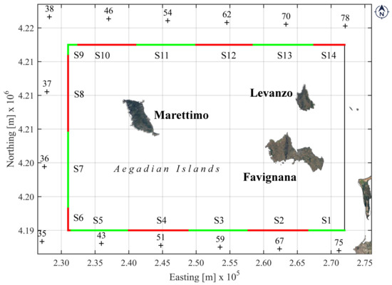
Figure 3.
The coloured rectangle is the SWAN model domain. Each side of the rectangle is divided in sectors, named by an upper-case letter (S1, S2, ..., S14) representing different offshore boundary conditions (see Table 1). The crosses represent the point of hind-cast dataset by [41,42,43] used to force the model offshore boundary conditions.
In Figure 3, the domain perimeter is drawn with a rectangle with sides divided into red and green segments, respectively, named S1, S2, ..., S14. To each of these segments is assigned a different wave offshore boundary condition except for the not coloured side. The sea state assigned to each of the segments is obtained from dataset by Mentaschi et al. [41,42,43] represented in Figure 3 with cross points. These wave conditions were used to force SWAN propagation model and the correspondence among segment and re-analysis point is reported in Table 1.

Table 1.
Correspondence among segments and re-analysis points.
In order to use a parallel version of SWAN with a flexible mesh, a 2D triangular Delanuay grid was built. The Delenuay tesselation was used respecting these rules: (a) each set point (not all collinear among them) has only one Delanuay triangulation; (b) every triangulation maximizes the smallest internal angle between all possible triangulations and (c) Delenuay triangulation is the dual of Dirichlet tessellation [46]. The unstructured meshes allow high levels of resolution along a specific stretch of coastline but relatively low levels of resolution between distant coasts or islands. The implemented mesh of our model was constituted by 158,151 triangles and 80,250 nodes and covered an area of about 40.00 × 27.5 km (Figure 4).
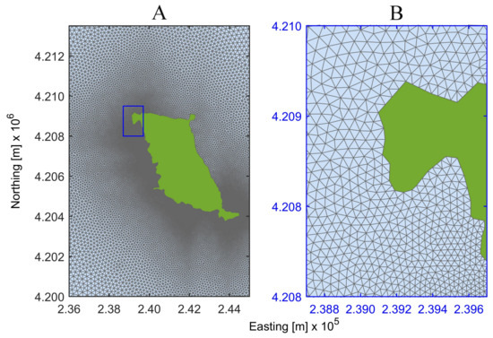
Figure 4.
(A) computational grid domain around the Marettimo Island. The right panel (B) shows the triangular unstructured mesh detail.
A density function was used to build the unstructured mesh in which the size of triangles depended on local water depth and wave length. Consequently, the triangles had longer sides in the regions with higher wavelength and water depth; the sides varied from a maximum of 600 m offshore to a minimum of 25 m nearshore. The elevations of the mesh nodes were determined by a linear interpolation of bathymetric data taken from the 17th nautical chart of the Istituto Idrografico della Marina Militare (the Italian Hydrographic Institute). The bathimetry of the domain area is shown in Figure 5.

Figure 5.
Bathymetry of the studied area. The colour bar shows the water depth in meters under the medium sea level.
The study area includes the continental shelf, with water depths between 741 and 2.5 m. The Aegadian archipelago seabed morphology was characterized by a continental shelf divided into two sectors: the Western sector with the Marettimo continental shelf and the eastern sector with the Favignana and Levanzo continental shelf. This last continental shelf is connected to the mainland with a depression of about 30 m depth. The two continental shelves are divided by the Marettimo channel with the NW-SE direction. The Marettimo continental shelf is the smallest and most isolated area Western Sicilian continental shelf and it is divided into two sectors: the area between the batimetric −10 m and −90 m with an average inclination of 0.9 and the area between the bathymetric −90 and −130 m with an average inclination of 10.
4. Validation of SWAN Wave Propagation
The propagation model was validated by comparing estimated by the model on six nodes with reanalysis data of the ERA-iterim project (European Centre for Medium-Range Weather Forecasts—ECMWF). The indices for estimating the goodness of validation bias, root mean square error (RMSE), Scatter index (SI) and regression line slope are reported in Table 2 for each of the six ECMWF nodes inside our propagation domain.
Table 2.
Comparison of the ECMWF and model values in the selected points of simulation domain (coordinates in ED50-UTM33N); particularly the indices are the bias, the root mean square error (RMSE), the Scatter Index (SI) and the regression line slope.
In particular, the SWAN simulation was run for the year 2000 every 10 min, while the comparison was carried out considering the values every 6 h, compatibly with the data availability in the time of ECMWF. Furthermore, the indices were estimated for all of six points globally, obtaining the following values: m (bias), m (RMSE), (SI Scatter Index) and (slope). This analysis demonstrated an adequate agreement of two data-sets and then the model validity is confirmed.
5. Results and Discussion
5.1. Offshore Analysis
In Figure 6, Figure 7 and Figure 8, the energy flux was calculated for all the reference points using Equation (6). The point n.37 is the more energetic; being characterized by large numbers of significant wave heights higher than 4 m, the point n.54 presents the lowest values. In all of the points, the waves coming from the W-NW sector can be considered as dominant, being 25% of the total and being the most energetic ones.
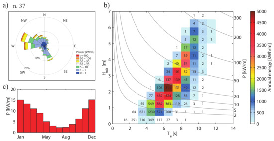
Figure 6.
Characterisation of mean yearly wave energy and wave energy flux climate at point n. 37; in (a), the wave energy flux rose; (b) the scatter plot of e , the colour scale indicates annual energy per meter of wave front (kWh/m), the numbers within the bins indicate the occurrence of sea states (hours/year) and the isolines specify the wave energy flux; (c) the histograms of the monthly mean wave energy flux.
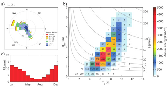
Figure 7.
Characterisation of mean yearly wave energy and wave energy flux climate at point n.51; in (a), the wave energy flux rose; (b) the scatter plot of e , the colour scale indicates annual energy per meter of wave front (kWh/m), the numbers within the bins indicate the occurrence of sea states (hours/year) and the isolines specify the wave energy flux; (c) the histograms of the monthly mean wave energy flux.
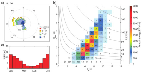
Figure 8.
Characterisation of mean yearly wave energy and wave energy flux climate at point n.54; in (a), the wave energy flux rose; (b) the scatter plot of e , the colour scale indicates annual energy per meter of wave front (kWh/m), the numbers within the bins indicate the occurrence of sea states (hours/year) and the isolines specify the wave energy flux; (c) the histograms of the monthly mean wave energy flux.
It should be emphasized that storms coming from the direction of SW are a specific characteristic of this area of the Tyrrhenian sea: this direction is associated with Sirocco, a wind coming from the Sahara, which often can be associated with storms and heavy rain lasting about four days. As regards the points n.37 and n.51, it can be observed that they present very similar energetic patterns, but n.37 is slightly more energetic because of more numerous and more energetic waves coming from the Western direction. Point n.54 is less energetic than other points but has a more uniform distribution of energy among the directions.
In Figure 6, Figure 7 and Figure 8, the wave power matrix or scatter wave energy flux diagram are also reported (subplot b). The area within each diagram was divided into bins of 0.5 m and 1.0 s (; ). The number inside each bin indicates the mean occurrence (hours per year) of sea states having and falling within the respective ranges relating to the bin itself. The colour of each bin indicates the mean annual energy per meter of the wave front (kWh/m); the grey lines represent wave energy flux isolines calculated by Equation (6). The above-mentioned figures include also the monthly mean wave energy flux for the three reference points (green circle Figure 2b); the bulk of wave energy flux is available in January, February, March, November, and December, May and September have a Energy flux between 5 and 3 kW/m, while, during the months of June, July and August, the flux of energy is very low.
In order to highlight the seasonal and temporal variability of the wave energy resource, different variability indicators [7] were calculated (Table 3). The adopted indicators are defined in the following expressions:
Table 3.
Statistical energy parameters at each reference point; is the Coefficient of Variation, is the Seasonality Variability index, is the Monthly Variability index, the mean wave energy flux, and the total wave energy in the average year.
In the aforementioned equations, COV (Equation (8)) is the coefficient of variations, SV (Equation (9)) is the seasonal variability index, and MV (Equation (10)) is the monthly variability index. In Equations (8)–(10), is the standard deviation, is the mean value of the time series, and are the maximum and the minimum seasonal energy, and are the maximum and the minimum monthly energy and is the mean yearly energy.
Figure 9 shows the monthly distribution of wave energy flux of the 14 nodes surrounding the nearshore propagation zone (green and red points of Figure 2). The maximum value of energy flux, 15.07 kW/m, is reached at point n. 37 in December.
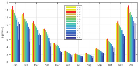
Figure 9.
Monthly average wave energy flux per unit of crest of all 14 reanalysis points corresponding to the 32-year time interval considered (1979–2010).
Figure 10 shows the distribution of average wave energy flux per unit of crest (), respectively, for winter, spring, summer and autumn.
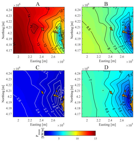
Figure 10.
Distribution of the average wave energy flux of Aegadian islands area (ED50-UTM33N). The isolines represents the wave energy flux [kW/m]. (A) winter months (December, January, February); (B) spring months (March, April, May); (C) summer (June, July, August) and (D) autumn (September, October, November).
These distributions were obtained interpolating the values of the wave reanalysis data during the period (1 Jannuary 1979–31 December 2010). In winter (Figure 10A), varies from 5 kW/m in stretch between Sicily and the Aegadian islands group, up to 15 kW/m off Marettimo island. In the spring months (Figure 10B), ranges from 2 kW/m to 9 kW/m, while, in summer, has a small variation (1.5–3 kW/m). In autumn, the distribution is similar to the spring one, but the values are 18% lower than spring. These results prove that the area off the northwest coast of Marettimo is the most promising in terms of renewable energy production.
5.2. Nearshore Analysis Results
In order to highlight the presence of energy flux concentration, the result of the SWAN model are represented in terms of mean energy flux between 2009 and 2010 (Figure 11). This time period was chosen only to better visualize the hotspots in the studied area. The western sector of the Aeolian islands is the most exposed to heavy storms and, consequently, in this area are located the highest values of available energy, as shown in Figure 12 and Figure 13.
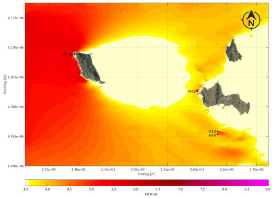
Figure 11.
The four energetic hotspots of the Aegadian archipelago in the period between 2009 and 2010. The colour bar shows the mean yearly wave energy flux [kW/m], the crosses represent the hotspots HT1, HT2, HT3 and HT4.
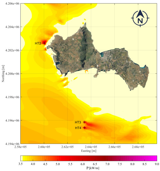
Figure 12.
The hotspots near Favignana in the period between 2009 and 2010. The colour bar shows the mean yearly wave energy flux [kW/m], and the crosses represent the hotspots HT2, HT3 and HT4.
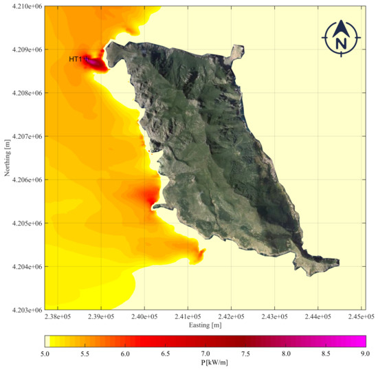
Figure 13.
The hotspots near Marettimo in the period between 2009 and 2010. The colour bar shows the mean yearly wave energy flux [kW/m], and the cross represents the hotspot HT1.
Owing to the covering action of Marettimo and Favignana island, in the central and eastern area of the archipelago there is low energy availability. The highest value of energy are found in the hotspot points that are shown as cross in Figure 11, Figure 12 and Figure 13. It is clear that a higher energy availability in the hotspots is due both to the meteo-marine conditions and to the morpho-bathimetric features.
The hotspot number 1, HT1, is localized close to the slope of continental shelf of the Marettimo island. The HT2 is positioned West of Favignana island and is farther from the continental shelf margin than HT1 (about 5 km far). Nevertheless, in this area, the bottom morphology is very complex because of the presence of several paleo-cliffs. It is important to highlight that, in this seabed, there are sea terraces with variable depth (30–45 m, 50–72 m e 75–85 m) which indicates sea level rise during the time. The HT3 and HT4 points are localized south of Favignana island close to isolated reliefs whose peaks reach a few meters under the sea.
Table 4 lists the statistical energy parameters at each hot-spot point compared with the mean significant wave height, the standard deviation and the maximum significant wave height. In Figure 13, only one hotspot (HT1) was detected with a maximum wave energy flux of 9 kW/m. The greatest numbers and highest storms came from 292.5 and 202.5, thus the eastern and southern coasts are practically covered from wave coming from these directions. On the southwestern coast, corresponding to other headlands, there are also energetic areas with energy flux values between 5.5 kW/m and 6.5 kW/m. Figure 12 detected three hotspots (HT2, HT3 and HT4) with a maximum wave energy flux of 6.5 kW/m. The HT3 and HT4 hotspots are offshore points with an energetic area, oriented W-E, of about 1 km and with a maximum energy flux of 6.5 kW/m. For each hotspot, Figure 14, Figure 15, Figure 16 and Figure 17 show both the mean yearly wave energy and the mean early wave energy flux climate. The above-mentioned figures for each hotspot show that (a) the energy flux rose, and (b) the scatter plot of the yearly energy in terms of and as described in Section 3.2 and (c) the monthly wave energy flux histogram. The energy results in terms of mean and maximum values are summarised in Table 4.
Table 4.
Statistical energy parameters at each hot-spot point; the mean significant wave height, STD standard deviation of , maximum significant wave height, the mean wave energy flux, the maximum wave energy flux and the total wave energy in the average year.
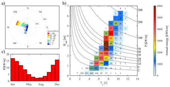
Figure 14.
Characterisation of mean yearly wave energy and wave energy flux climate at point at point HT1; (a) the wave energy flux rose; (b) the scatter plot of e , the colour scale indicates annual energy per meter of wave front (kWh/m), the numbers within the bins indicate the occurrence of sea states (hours/year) and the isolines specify the wave energy flux; (c) the histograms of the monthly mean wave energy flux.
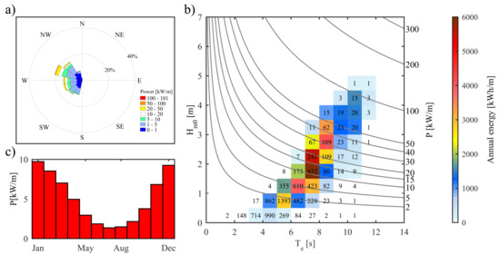
Figure 15.
Characterisation of mean yearly wave energy and wave energy flux climate at point HT2; (a) the wave energy flux rose; (b) the scatter plot of e , the colour scale indicates annual energy per meter of wave front (kWh/m), the numbers within the bins indicate the occurrence of sea states (hours/year) and the isolines specify the wave energy flux; (c) the histograms of the monthly mean wave energy flux.
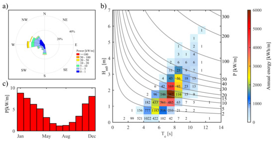
Figure 16.
Characterisation of mean yearly wave energy and wave energy flux climate at point HT3; (a) the wave energy flux rose; (b) the scatter plot of e , the colour scale indicates annual energy per meter of wave front (kWh/m), the numbers within the bins indicate the occurrence of sea states (hours/year) and the isolines specify the wave energy flux; (c) the histograms of the monthly mean wave energy flux.
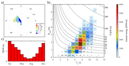
Figure 17.
Characterisation of mean yearly wave energy and wave energy flux climate at point HT4; (a) the wave energy flux rose; (b) the scatter plot of e , the colour scale indicates annual energy per meter of wave front (kWh/m), the numbers within the bins indicate the occurrence of sea states (hours/year) and the isolines specify the wave energy flux; (c) the histograms of the monthly mean wave energy flux.
The HT1 hotspot (Figure 14) is near the northwest headland of the Marettimo island, where the coastline is very winding with cliffs and small bays. This highly energetic point is located near to the boundary between the A and B reserve zones. The HT1 point has a mean energy flux of 8.53 kW/m and a total wave energy in the average year of 69.67 MWh/m. The maximum yearly energy is carried by 189 waves with m and s, is 5 168 kWh/m. As can be deduced from the isoline shown in the scatter plot of Figure 14, these 189 waves have an energy flux of 30 kW/m. These results prove that the highest energetic area around the Sicily is not (as assessed by [6]) the zone between Marettimo and Favignana, but this is the West sea area off Marettimo. Indeed, Liberti et al. [6] found near Favignana the most energetic Sicilian point with an average energy flux of 7.3 kW/m and an energy per year of 64.00 MWh/m (less than HT1). Moreover, Monteforte et al. [8] also found near Marsala (TP) a point with a mean energy flux of 5.6 kW/m and a total wave energy in the average year of 48.49 MWh/m. In the present study, it is clearly shown that the point HT1 is the most energetic one together with the area just West of Marettimo island (see Figure 11). The HT2 hotspot (Figure 15) is one of the three energetic points near the Favignana coast and it has a mean energy flux of 4.99 kW/m and a total wave energy in the average year of 40.78 MWh/m. The maximum yearly energy carried by 432 waves with m and s, is 4412 kWh/m. As can be deduced from the isoline shown in the scatter plot of Figure 15, the energy flux corresponding to maximum energy availability is 10 kW/m. Finally, HT3 (Figure 16) and HT4 (Figure 17) are 4.47 km offshore the southern island side at 480 m distance one from each other. The HT3 is the lowest energetic point, whereas the HT4 hotspot ( = 5.03 kW/m = 41.11 MWh/m) is the second highest energetic point (Figure 17).
The energy results described above are also strictly linked to two main issues typical of these islands, such as coastal erosion and their dependence by non-renewable energy sources. The first issue is due to the strong erosive wave action on the cliffs made by fractured and/or fissured rocks. The consequence is that the northwestern side of Marettimo has an high erosion hazard. This erosion process is the result of the strong cliff retreating during the time. The cliffs under wave action are subject to the toe scour due to a quick enlargement of the wave cut notch. As time increases, toe scour produces rock falls and consequentially the cliff retreating. The retreat velocity is linked to the huge wave energy dissipated through the rock-wave interaction. The second issue is that the distance of Marettimo from Sicily is crucial for the provisioning of electrical energy supply for the island. Therefore, the wave energy could enable the island to support itself in an energetically sustainable manner. Finally, it is important to highlight that the use of the energetic devices would not generate negative effects on the surrounding environment. Indeed, once the energetic devices were deployed, these can become new habitats for different marine species. The energetic devices will be able to provide fixing surfaces for several algae and invertebrates, becoming in this way colonized by organisms. This aspect will be linked to the planning of energy devices; in particular, the designer will have to account of the biofouling.
6. Conclusions
Wave energy flux around the Aegadian Archipelago was examined using high resolution (in space and time) reanalysis wave data from [41,42,43]. The analysis detected the West area in front of the Aegadian islands as an important energetic site. In this area, several numerical simulations of wave propagation were conducted in a non-stationary mode. The near-shore analysis detected four energetic hotspots close to the coasts of the islands. In particular, the HT1 point is located inside a small shoal near the northwest headland of Marettimo island; the HT2 point is located near the West headland of Favignana island; the HT3 and HT4 points are located inside a shoal, about five kilometers south of Favignana island. A numerical analysis considering a 32-year period allowed us to assess the mean annual wave energy as well as the average and the maximum wave energy flux in the hotspot points, proving HT1 as the most energetic of the Sicilian area. The energy availability during the year is focused on the winter and autumn period with lower energy values during the summer period (June, July and August). The HT1 point, with an energy flux of 8.53 kW/m and a total wave energy of 69.67 MWh/m per year, is one of the most energetic Mediterranean nearshore points. All the hotspot points here that were found to meet the needs of islands to improve the future green energy production. Therefore, the wave energy resource for such islands could quickly become a viable alternative to conventional energy resources based on fossil fuels. Moreover, this hotspot could be very useful in order to mitigate, in synergy with other coastal defence systems, the erosion hazard. This study proves that the more energetic nearshore Sicilian area is not between Marettimo and Favignana but is about 1 km west of Marettimo. In conclusion, robustness, reliability and convenience of the energetic devices are the most important aims to be achieved in the research of the coming years. The most accurate assessment of the wave energy resource in Sicily is important for the effective functioning of the devices in terms of control, reliability and energy supply to the network. A better understanding of the interaction between the resources and the device will make it possible to achieve more and more optimal converters.
Author Contributions
Data curation, G.B.; Formal analysis, C.L.R. and G.M.; Methodology, C.L.R., G.M., G.B. and G.C.; Software, C.L.R.; Supervision, G.C.; Validation, G.M., C.L.R. and G.C.; Writing—original draft, C.L.R. and G.M.; Writing—review & editing, C.L.R., G.M., G.B. and G.C.
Funding
This research was funded by the SIMIT THARSY Tsunami Hazard Reduction System C1-3.2-5-INTERREG V-A Italia-Malta.
Acknowledgments
We thank Massimiliano Monteforte for assistance with numerical modelling of the studied area, and for sharing with us his expertise in coastal engineering.
Conflicts of Interest
The authors declare no conflict of interest.
Abbreviations
The following abbreviations are used in this manuscript:
| WRF | Weather Research and Forecast |
| SWAN | Simulating WAves Nearshore |
| WEC | Wave Energy Converters |
| SAPS | Stand-Alone Power System |
| MPA | Marine Protected Areas |
| RES | Renewable Energy Systems |
| RON | Rete Ondametrica Nazionale (Italian wave buoy network) |
| REDEXT | RedExterior |
| DICCA | Dipartimento di Ingegneria Civile, Chimica e Ambientale |
| COV | Coefficient of Variation |
| SV | Seasonality Variability index |
| MV | Monthly Variability index |
| ECMWF | European Centre for Medium-Range Weather Forecasts |
| ERA-Interim | ECMWF Reanalysis (from January 1989 onward) |
| RMSE | Root Mean Square Error |
| SI | Scatter Index |
| HT1 | Hotspot 1 |
| HT2 | Hotspot 2 |
| HT3 | Hotspot 3 |
| HT4 | Hotspot 4 |
References
- Henderson, R. Design, simulation, and testing of a novel hydraulic power take-off system for the Pelamis wave energy converter. Renew. Energy 2006, 31, 271–283. [Google Scholar] [CrossRef]
- Bozzi, S.; Giassi, M.; Miquel, A.M.; Antonini, A.; Bizzozero, F.; Gruosso, G.; Archetti, R.; Passoni, G. Wave energy farm design in real wave climates: The Italian offshore. Energy 2017, 122, 378–389. [Google Scholar] [CrossRef]
- Silva, D.; Rusu, E.; Soares, C.G. Evaluation of various technologies for wave energy conversion in the Portuguese nearshore. Energies 2013, 6, 1344–1364. [Google Scholar] [CrossRef]
- Rusu, E. Evaluation of the wave energy conversion efficiency in various coastal environments. Energies 2014, 7, 4002–4018. [Google Scholar] [CrossRef]
- Mørk, G.; Barstow, S.; Kabuth, A.; Pontes, M.T. Assessing the global wave energy potential. In Proceedings of the of 29th International Conference on Ocean, Offshore and Arctic Engineering, Shanghai, China, 6–11 June 2010; Volume 3, pp. 447–454. [Google Scholar]
- Liberti, L.; Carillo, A.; Sannino, G. Wave energy resource assessment in the Mediterranean, the Italian perspective. Renew. Energy 2013, 50, 938–949. [Google Scholar] [CrossRef]
- Besio, G.; Mentaschi, L.; Mazzino, A. Wave energy resource assessment in the Mediterranean Sea on the basis of a 35-year hindcast. Energy 2016, 94, 50–63. [Google Scholar] [CrossRef]
- Monteforte, M.; Lo Re, C.; Ferreri, G.B. Wave energy assessment in Sicily (Italy). Renew. Energy 2015, 78, 276–287. [Google Scholar] [CrossRef]
- Iuppa, C.; Cavallaro, L.; Vicinanza, D.; Foti, E. Investigation of suitable sites for Wave Energy Converters around Sicily (Italy). Ocean Sci. 2015, 12, 543–557. [Google Scholar] [CrossRef]
- Iuppa, C.; Cavallaro, L.; Foti, E.; Vicinanza, D. Potential wave energy production by different wave energy converters around Sicily. J. Renew. Sustain. Energy 2015, 7, 061701-1–061701-16. [Google Scholar] [CrossRef]
- Nezhad, M.M.; Groppi, D.; Rosa, F.; Piras, G.; Cumo, F.; Garcia, D.A. Nearshore wave energy converters comparison and Mediterranean small island grid integration. Sustain. Energy Technol. Assess. 2018, 30, 68–76. [Google Scholar]
- Franzitta, V.; Curto, D. Sustainability of the renewable energy extraction close to the Mediterranean islands. Energies 2017, 10, 283. [Google Scholar] [CrossRef]
- Franzitta, V.; Viola, A.; Curto, D.; Trapanese, M. Nexus water & energy: A case study of wave energy converters (WECs) to desalination applications in Sicily. Int. J. Heat Technol. 2016, 34, S379–S386. [Google Scholar]
- Aristodemo, F.; Ferraro, D.A. Feasibility of WEC installations for domestic and public electrical supplies: A case study off the Calabrian coast. Renew. Energy 2018, 121, 261–285. [Google Scholar] [CrossRef]
- Lavidas, G. Energy and socio-economic benefits from the development of wave energy in Greece. Renew. Energy 2019, 132, 1290–1300. [Google Scholar] [CrossRef]
- Gonçalves, M.; Martinho, P.; Soares, C.G. Assessment of wave energy in the Canary Islands. Renew. Energy 2014, 68, 774–784. [Google Scholar] [CrossRef]
- Fernández Prieto, L.; Rodríguez Rodríguez, G.; Schallenberg Rodríguez, J. Wave energy to power a desalination plant in the north of Gran Canaria Island: Wave resource, socioeconomic and environmental assessment. J. Environ. Manag. 2019, 231, 546–551. [Google Scholar] [CrossRef] [PubMed]
- Rusu, E.; Soares, C.G. Wave energy pattern around the Madeira Islands. Energy 2012, 45, 771–785. [Google Scholar] [CrossRef]
- Rusu, L.; Soares, C.G. Wave energy assessments in the Azores islands. Renew. Energy 2012, 45, 183–196. [Google Scholar] [CrossRef]
- Iglesias, G.; Carballo, R. Wave power for la isla bonita. Energy 2010, 35, 5013–5021. [Google Scholar] [CrossRef]
- Gonçalves, M.; Martinho, P.; Soares, C.G. Wave energy conditions in the western French coast. Renew. Energy 2014, 62, 155–163. [Google Scholar] [CrossRef]
- Iglesias, G.; Carballo, R. Wave resource in El Hierro—An island towards energy self-sufficiency. Renew. Energy 2011, 36, 689–698. [Google Scholar] [CrossRef]
- Zanous, S.; Shafaghat, R.; Alamian, R.; Shadloo, M.; Khosravi, M. Feasibility study of wave energy harvesting along the southern coast and islands of Iran. Renew. Energy 2019, 135, 502–514. [Google Scholar] [CrossRef]
- Curto, D.; Trapanese, M. A Renewable Energy mix to Supply the Balearic Islands: Sea Wave, Wind and Solar. In Proceedings of the IEEE International Conference on Environment and Electrical Engineering and 2018 IEEE Industrial and Commercial Power Systems Europe (EEEIC/I&CPS Europe), Palermo, Italy, 12–15 June 2018. [Google Scholar] [CrossRef]
- Doorga, J.; Chinta, D.; Gooroochurn, O.; Rawat, A.; Ramchandur, V.; Motah, B.; Sunassee, S.; Samyan, C. Assessment of the wave potential at selected hydrology and coastal environments around a tropical island, case study: Mauritius. Int. J. Energy Environ. Eng. 2018, 9, 135–153. [Google Scholar] [CrossRef]
- Hirakawa, T. Wave energy resource assessment around Kyushu based on numerical hindcast. J. Renew. Sustain. Energy 2018, 10. [Google Scholar] [CrossRef]
- Rusu, E.; Onea, F. Estimation of the wave energy conversion efficiency in the Atlantic Ocean close to the European islands. Renew. Energy 2016, 85, 687–703. [Google Scholar] [CrossRef]
- Bernardino, M.; Rusu, L.; Soares, C.G. Evaluation of the wave energy resources in the Cape Verde Islands. Renew. Energy 2017, 101, 316–326. [Google Scholar] [CrossRef]
- Iglesias, G.; Carballo, R. Wave farm impact: The role of farm-to-coast distance. Renew. Energy 2014, 69, 375–385. [Google Scholar] [CrossRef]
- Bergillos, R.J.; Lopez-Ruiz, A.; Medina-Lopez, E.; Monino, A.; Ortega-Sanchez, M. The role of wave energy converter farms on coastal protection in eroding deltas, Guadalfeo, southern Spain. J. Clean. Prod. 2018, 171, 356–367. [Google Scholar] [CrossRef]
- Rusu, E.; Soares, C.G. Coastal impact induced by a Pelamis wave farm operating in the Portuguese nearshore. Renew. Energy 2013, 58, 34–49. [Google Scholar] [CrossRef]
- Zanopol, A.T.; Onea, F.; Rusu, E. Coastal impact assessment of a generic wave farm operating in the Romanian nearshore. Energy 2014, 72, 652–670. [Google Scholar] [CrossRef]
- Veigas, M.; Iglesias, G. Wave and offshore wind potential for the island of Tenerife. Energy Convers. Manag. 2013, 76, 738–745. [Google Scholar] [CrossRef]
- Rusu, E. Numerical Modeling of the Wave Energy Propagation in the Iberian Nearshore. Energies 2018, 11, 980. [Google Scholar] [CrossRef]
- Bozzi, S.; Archetti, R.; Passoni, G. Wave electricity production in Italian offshore: A preliminary investigation. Renew. Energy 2014, 62, 407–416. [Google Scholar] [CrossRef]
- Bizzozero, F.; Bozzi, S.; Gruosso, G.; Passoni, G.; Giassi, M. Spatial interactions among oscillating wave energy converters: Electricity production and power quality issues. In Proceedings of the 42nd Annual Conference on Industrial Electronics Society, Florence, Italy, 23–26 October 2016; pp. 4235–4240. [Google Scholar]
- Verao Fernandez, G.; Balitsky, P.; Stratigaki, V.; Troch, P. Coupling Methodology for Studying the Far Field Effects of Wave Energy Converter Arrays over a Varying Bathymetry. Energies 2018, 11, 2899. [Google Scholar] [CrossRef]
- Silva, D.; Rusu, E.; Guedes Soares, C. High-resolution wave energy assessment in shallow water accounting for tides. Energies 2016, 9, 761. [Google Scholar] [CrossRef]
- Himes, A.H. Performance indicator importance in MPA management using a multi-criteria approach. Coast. Manag. 2007, 35, 601–618. [Google Scholar] [CrossRef]
- Manno, G.; Lo Re, C.; Ciraolo, G. Uncertainties in shoreline position analysis: The role of run-up and tide in a gentle slope beach. Ocean Sci. 2017, 13, 661. [Google Scholar] [CrossRef]
- Mentaschi, L.; Besio, G.; Cassola, F.; Mazzino, A. Developing and validating a forecast/hindcast system for the Mediterranean Sea. J. Coast. Res. SI 2013, 65, 1551–1556. [Google Scholar] [CrossRef]
- Mentaschi, L.; Besio, G.; Cassola, F.; Mazzino, A. Problems in RMSE-based wave model validations. Ocean Model. 2013, 72, 53–58. [Google Scholar] [CrossRef]
- Mentaschi, L.; Besio, G.; Cassola, F.; Mazzino, A. Performance evaluation of Wavewatch III in the Mediterranean Sea. Ocean Model. 2015, 90, 82–94. [Google Scholar] [CrossRef]
- Ardhuin, F.; Rogers, E.; Babanin, A.V.; Filipot, J.F.; Magne, R.; Roland, A.; Van Der Westhuysen, A.; Queffeulou, P.; Lefevre, J.M.; Aouf, L.; et al. Semiempirical dissipation source functions for ocean waves. Part I: Definition, calibration, and validation. J. Phys. Oceanogr. 2010, 40, 1917–1941. [Google Scholar] [CrossRef]
- Booij, N.; Ris, R.; Holthuijsen, L.H. A third-generation wave model for coastal regions: 1. Model description and validation. J. Geophys. Res. Oceans (1978–2012) 1999, 104, 7649–7666. [Google Scholar] [CrossRef]
- Bowyer, A. Computing dirichlet tessellations. Comput. J. 1981, 24, 162–166. [Google Scholar] [CrossRef]


© 2019 by the authors. Licensee MDPI, Basel, Switzerland. This article is an open access article distributed under the terms and conditions of the Creative Commons Attribution (CC BY) license (http://creativecommons.org/licenses/by/4.0/).