Design of a Continuous Signal Generator Based on Sliding Mode Control of Three-Phase AC-DC Power Converters


1
Department of Electrical Engineering, Jordan University of Science and Technology, Irbid 22110, Jordan
2
Bioprocesses Department at the UPIBI, The National Polytechnic Institute, Mexico City 07340, Mexico
3
Department of Electrical and Computer Engineering, The Ohio State University, Columbus, OH 43210, USA
*
Author to whom correspondence should be addressed.
Energies 2019, 12(23), 4468; https://doi.org/10.3390/en12234468
Submission received: 11 October 2019
/
Revised: 15 November 2019
/
Accepted: 18 November 2019
/
Published: 23 November 2019
(This article belongs to the Special Issue Sliding Mode Control of Power Converters in Renewable Energy Systems)
Abstract
:In recent years, hundreds of technical papers have been published which describe the use of sliding mode control (SMC) techniques for power electronic equipment and electrical drives. SMC with discontinuous control actions has the potential to circumvent parameter variation effects with low implementation complexity. The problem of controlling time-varying DC loads has been studied in literature if three-phase input voltage sources are available. The conventional approach implies the design of a three-phase AC/DC converter with a constant output voltage. Then, an additional DC/DC converter is utilized as an additional stage in the output of the converter to generate the required voltage for the load. A controllable AC/DC converter is always used to have a high quality of the consumed power. The aim of this study is to design a controlled continuous signal generator based on the sliding mode control of a three-phase AC-DC power converter, which yields the production of continuous variations of the output DC voltage. A sliding mode current tracking system is designed with reference phase currents proportional to the source voltage. The proportionality time-varying gain is selected such that the output voltage is equal to the desired time function. The proposed new topology also offers the capability to get rid of the additional DC/DC power converter and produces the desired time-varying control function in the output of AC/DC power converter. The effectiveness of the proposed control design is demonstrated through a wide range of MATLAB/Simulink simulations.
1. Introduction
Sliding mode control (SMC) has high order reduction property, good dynamic performance, low sensitivity to disturbances, and plant parameter variations, allowing SMC to handle nonlinear systems with uncertain dynamics and disturbances. Additionally, SMC is decoupled into independent lower dimensional subsystems, simplifying feedback control design. These properties allow SMC to be used in a wide range of applications such as automotive control, robotics, aviation, power systems, power electronics, and electric motors [1,2,3,4,5].
Power electronic converters are controlled by switching electrical components, which can produce two dissimilar values at the gating terminals [6,7]. Their controlled variables may take values from a two valued discrete set. Moreover, linearization is not required [1,2,8,9]. Hence, SMC is a preferred method to realize the control of power converter devices.
Within the wide diversity of available power electronic devices, the well-known three-phase AC/DC is commonly applied in energy conversion plants. Nevertheless, inherent complications appear with regards to reactive power generation, as well as the higher harmonic content in the input current. These characteristics appear as practical disadvantages that have become more relevant as the AC/DC converter capacity turn out to be larger and larger [10,11,12].
The idealized AC/DC converter shows up as a constant DC voltage as controlled output (or current) and a sinusoidal input set of currents at unity power factor at the AC line. Nevertheless, the current technology of thyristor phase-controlled converters has two intrinsic disadvantages: First, the larger firing angle, the smaller power factor; and second, the line current has moderately large harmonics components [13,14]. As AC/DC converters are more and more controlled using PWM switching patterns, the input as well as the output performances improve. These PWM AC/DC converters offer numerous advantages compared to some traditional rectifiers [15,16]: Unity power factor, low harmonic components in input current, bidirectional power flow, and low ripple in output voltage. These characteristics make simpler the filtering processes on both AC and DC sides of the proposed converter [1,2,10,16].
Conventional control design techniques for this type of power converter device usually solve the maintaining of the DC output voltage at a given reference level firstly, and at second place, try to seek for the minimization of high order harmonics and reactive power at the input. SMC of AC/DC power converters, presented in [1], offers the inverse sequence of actions. First, a current tracking system was designed with sinusoidal current references that are proportional to the AC input voltages with a constant gain of proportionality. This automatically sets the reactive power to zero. Second, it was proven that the output voltage will be constant and only depends on the amplitude of the reference input. However, the proposed control method requires an additional DC/DC converter to control the DC load. This introduces the following control design challenge: Is it possible to avoid using an additional DC/DC converter and generate any arbitrary desired time varying function at the output of the AC/DC converter such that the DC load can be directly controlled?
The main contributions of this study are:
(a) Sliding mode control is an appropriate tool for application for wide range of power converters. The first publications on DC/DC converters [1,2,3,4,7,8] demonstrated its efficiency. The methods of minimization heat losses and of chattering amplitude based on harmonic cancellation principle, switching frequency control for DC/DC converters can be found in [2,3,4]. Multidimensional sliding modes were utilized in power converters to control AC load with DC energy source [5,6]. The design methodology to control output constant voltage and power factor simultaneously for AC-DC converter was developed in [7]. We are not aware of publications with our problem statement—to have an arbitrary time function (not constant) in the output of AC/DC converter. The attempts to find time of the varying gain as an algebraic state function of state failed, because it should satisfy the algebraic equation.
(b) A SMC has been proposed to generate continuous waveforms based on a controlled switched sequence of a three-phase AC-DC converter. This achievement was a consequence of solving a trajectory tracking of estimated reference currents. The realization of such tracking enforces the production of bounded derivative DC output voltage. The tracking controller implemented a time-varying relationship between the currents and voltages on the AC side of the converter. Such given positive relation between voltage and current justified the positive power efficiency of the controlled power converter.
2. Problem Statement
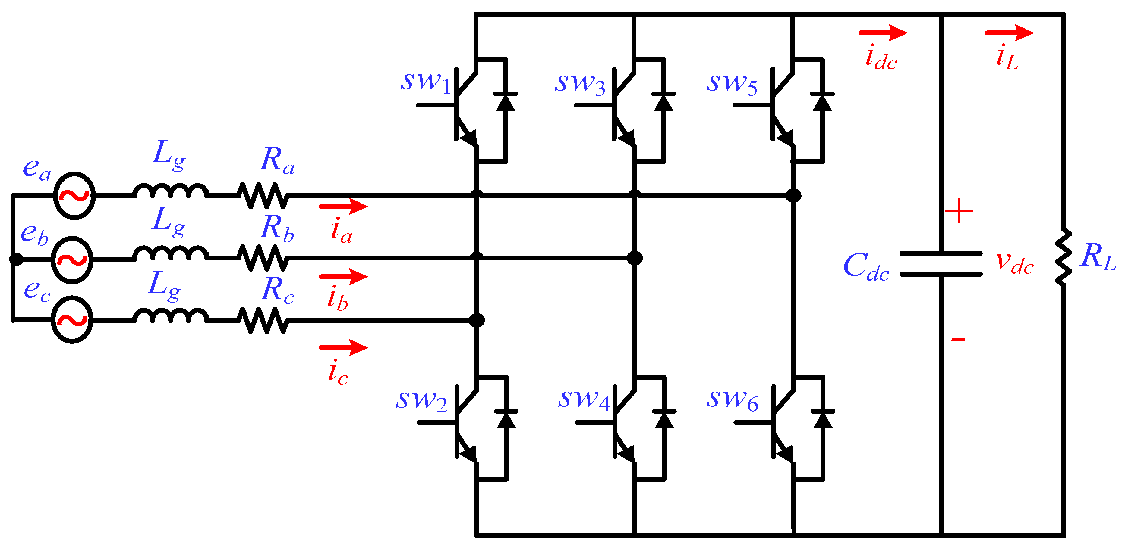
The design problem considered in this study is the generation of switching commands for the power electronics-switching elements of the AC/DC converter (shown in Figure 1) in such a way that the output voltage can track the desired output of the converter f(t), which should be positive. This condition agrees with the classical realization of AC/DC, buck, and boost power converters. Since the input AC voltage is bounded, the output capacitor C can be charged at a limited velocity, which means that the time derivative should be bounded. Therefore, the problem can be described as fixing the switching sequence such that:
The power efficiency can be maximized if each input phase current of the power converter is proportional to the corresponding phase voltage with a positive gain. Therefore, the objective of this paper is to design a new control algorithm such that the input phase currents track preselected reference inputs and the positive gain of the proportionality is selected as a time varying function. Accordingly, the output voltage is equal to the desired function .
3. Circuit Model of the Three-Phase PWM AC/DC Voltage Source Converter Scheme
Figure 1 shows the three-phase PWM AC/DC voltage source converter scheme. are the balanced three-phase AC input voltages; is dc-link current; is a resistive load connected to the DC side; is the load current; are the three-phase AC input currents; is the dc-link capacitance is dc-link voltage; and represent the grid-side resistance and inductance, respectively.
The balanced three-phase AC input currents are given by:
where are the AC side phase voltages of the converter. The balanced three-phase AC voltages are given by:
Here, is the AC power source angular frequency and is the amplitude of the phase voltages. Assume that , , , then Equations (2)–(4) can be re-written in a compact form:
Define the switching function of each switch as:
As a result, the voltage vector can be given in terms of the switching functions as:
By substituting Equation (10) into (8), the AC input current equations can be given by:
In conclusion, the output voltage can be given by:
4. Sliding Mode Current-Tracking Control
As previously indicated, a sliding mode-based current tracking system is designed such that sinusoidal reference inputs are tracked by phase currents proportional to input AC voltages. Rewriting Equation (11) as:
where, matrix is given by:
Since the sum of the three-phase currents is zero, only three state variables should be controlled in a system with a three-dimensional control vector S: Two phase currents and output voltage. However, because matrix Γ0 is singular, the conventional sliding mode approach cannot be directly applied. Therefore, a tracking system for two phase currents only is first designed. As a result, the sliding mode should be enforced on the intersection of two surfaces and , or in a vector form:
Excluding the phase current yields:
where is a 2 × 3 matrix given by:
The ideal tracking system is based on the Lyapanov function:
has to be negative definite and calculated on the system trajectory when selecting discontinuous control:
where is state function, which does not depend on control. and are given by:
If is large enough, can be suppressed with control S given by:
such that . As a result, tends to zero and becomes zero after a finite time interval [17,18,19]. Consequently, sliding mode occurs with . Therefore, the current tracking system is developed with sinusoidal current references proportional to the input AC voltages as:
Calculate the equivalent control [2]:
The three phase input currents can also be expressed as:
The sliding mode equation can be obtained by substituting Equations (24) and (25) into (17):
After sliding mode occurs :
Therefore,
where, .
It can be shown that the output voltage is given by:
If , then the gain K should satisfy the differential equation
Assume that is the voltage reference and , then the equation
can be simulated in the controller,
Equation (32) shows that and the output voltage tends to be the reference input . Assume that
then:
If , then
It means that
and is always positive if . This corresponds to a power factor equal to 1 () for a high enough amplitude of the input source voltage. It is important that in (29) will be negative for high enough values of K. Hence, the gain K is bounded.
Remark: The implementation of the proposed controller in embedded systems requires the online measurement of the dc voltage at the capacitor and the possibility of realizing fast enough oscillations on the switching electronic elements. This part of the problem can be solved using available fast dedicated microcontrollers devices. Notice that the accuracy of the produced signal is a function of the relative relationship between the switching devices operation frequency and the main frequency components of the desired signals. Evidently, the exact reconstruction of the desired signal cannot be acquired. Nevertheless, the studies regarding discrete implementation of sliding mode has shown that the accuracy of the sliding mode realization is proportional to the square power of the sampling period if the explicit discretization is considered. For more details on the implementation issues, please see references [20,21,22,23]. Remark: The proposed control strategy offers an alternative to some other sliding mode controllers designs considering adaptive pulse width modulation [24], sub-optimal regulation [25], and multitype restrictive [26] approaches which have been applied on DC-DC power converters to obtain arbitrary signals. However, not one of them has been tested on the AC-DC device.
5. Simulation Results
In order to evaluate the proposed sliding mode control design procedure several computer simulations have been conducted using MATLAB/Simulink software. The control algorithm is represented in the following flow diagram (Figure 2):
Different generated signals have confirmed the abilities of the proposed continuous waveform generators.
The simulation was performed for power converter governed by Equation (10) with control (21) and different desired functions f(t) in the converter output. The differential equation for time varying gain K(t) in Equation (29).
5.1. Sinusoidal Waveform Generation
The first signal is a pure sinusoidal waveform, which corresponds to a traditional signal used in diverse signal generators. The selected reference waveform is:
The results of the simulation are shown in Figure 3.
The input currents obtained by the application of the suggested first sliding-mode controller show a modulated sinusoidal shape in all three branches (Figure 4).
The time dependence of the current also shows the expected modulation with the frequency of the desired output current, which is 15 Hz (Figure 5).
The phase relations between the input currents hold both in the transient and the steady state periods. In the period between 0.0 and 0.1 s, the current decreases exponentially to the steady state, which is detected after 0.1 s. A phase shift of 2/3 is evidenced, which also confirms the efficiency of the suggested controller. Notice that the simultaneous dependence of with respect to the reference waveform as well as its derivative does not relate it to the reference voltage form. The gain variation is continuous but not necessarily differentiable, considering the gain structure estimated in this study.
5.1.1. Variable Frequency Sinusoidal Waveform Generation
The second proposed reference signal is a composite sinusoidal waveform, which corresponds to a class of simplified chirp signal. Such waveforms can be used for testing the spectral response of diverse systems for calibration purposes. The selected composite sinusoidal reference waveform is:
Once more, the selected bias constants mean a positive waveform. The selected transition times between the sinusoidal forms can design a continuous composite waveform with a bounded derivative. The simulation results are shown in Figure 6.
The input currents agree with the variation of the sinusoidal frequency by the application of the suggested first sliding mode controller with the corresponding modulated sinusoidal shape in all three branches (Figure 7).
When looking at the time variation of the gain K for the controller, notice that the simultaneous dependence of K with respect to the reference waveform, as well as its derivative does not relate it to the reference voltage form. The second waveform considered in this study produces a smoother variation of the gain K. The gain variation is continuous considering the gain structure estimated in this study (Figure 8).
5.1.2. Triangular Waveform Generation
The third suggested reference signal is a triangular signal, which is also a common signal used in the calibration of diverse devices. Notice that this signal has a bounded but not continuous derivative. Consequently, the suggested controllers are applicable (Figure 9).
For the class of triangular signal, the controller succeeded at reconstructing the suggested reference signal as shown in Figure 9a. Consequentially, the tracking error of the reference voltage is reduced to less than 0.05% over a period of 0.08 s (Figure 9b).
The time variation of the gain for the controller with the reference triangular signal appears in Figure 10. The gain variation function is continuous.
Even if the exact sliding motion can be acquired if and only if the switches in the power converter oscillate at the infinite frequency, the current available technology allows to oscillate at such high frequencies ensuring the existence of the practical sliding motion. On the other hand, the required high frequency oscillations of the sliding mode may produce heath losses which could damage the switching circuit. In all the presented cases, chattering phenomenon should mentioned always when applying sliding mode control. The set of chattering suppression methods has been developed in the framework of sliding mode control theory. They are surveyed in [27]. The harmonics cancellation principle is the most efficient for power converters and can be applied for our case. The design idea consists in using several parallel converters with controlled phases such that high order harmonics can be cancelled.
6. Conclusions
This paper has presented the control design procedure to directly control DC loads using a three-phase voltage source without a rectifier. It consists of two steps. First, the current tracking problem is solved with reference currents proportional to phase voltages. Then, the time varying proportionality coefficient is selected such that the output voltage is equal to the desired time function. It has been shown that the proportionality gain should satisfy the first order differential equation, which is implemented in the controller. The behavior of the system with a positive coefficient is equivalent to having a unity power factor. Stability of the complete system (the power converter and controller dynamics) was also proved. A wide range of computer simulations were provided to demonstrate efficiency of the proposed control design for different types of sinusoidal and triangular functions as voltage reference inputs.
Author Contributions
Formal analysis, Y.M.A., I.C., and V.U.; Investigation, Y.M.A., I.C., and V.U.; Methodology, Y.M.A., I.C., and V.U.; Supervision, V.U.; Validation, V.U.; Writing—original draft, Y.M.A., I.C., and V.U.
Funding
This research work was partially funded by the [Consejo Nacional de Ciencia y Tecnología] grant number [CB-20181457] and the [Instituto Politécnico Nacional] grant number [SIP-20191724].
Conflicts of Interest
The authors declare no conflict of interest.
References
- Alsmadi, Y.; Utkin, V.; Haj-Ahmed, M.; Xu, L.; Abdelaziz, A. Sliding-mode control of power converters: AC/DC converters & DC/AC inverters. Int. J. Control 2018, 91, 2573–2587. [Google Scholar]
- Utkin, V.; Guldner, J.; Shi, J. Sliding Mode Control in Electro-Mechanical Systems; CRC Press, Taylor Francis Group: London, UK, 2009. [Google Scholar]
- Utkin, V. Sliding Modes in Control and Optimization; Springer: Berlin, Germany, 1992. [Google Scholar]
- Utkin, V. Sliding Modes and Their Application in Variable Structure Systems; MIR Publishers: Moscow, Russia, 1978. [Google Scholar]
- Bartolini, G.; Fridman, L.; Pisano, A.; Usai, E. Modern Sliding Mode Control Theory: New Perspectives and Applications; Springer: Berlin, Germany, 2008. [Google Scholar]
- Mohan, N.; Undeland, T.; Robbins, W. Power Electronics: Converters, Applications, and Designs; John Wiley Sons, Inc: Hoboken, NJ, USA, 2003. [Google Scholar]
- Krein, P. Elements of Power Electronics; Oxford University Press: Oxford, UK, 1997. [Google Scholar]
- Sira-Ramirez, H.; Ortigoza, R.S. Control Design Techniques in Power Electronics Devices; Springer: Germany, Berlin, 2006. [Google Scholar]
- Martinez-Salamero, L.; Cid-Pastor, A.; Giral, R.; Calvente, J.; Utkin, V. Why is sliding mode control methodology needed for power converters? In Proceedings of the 14th International Power Electronics and Motion Control Conference (EPE/PEMC), Ohrid, Macedonia, 6–8 September 2010; Volume 1, pp. S9-25–S9-31. [Google Scholar]
- Chen, L.; Blaabjerg, F.; Frederiksen, P.S. An improved predictive control for three-phase PWM AC/DC converter with low sampling frequency. In Proceedings of the 20th International Conference on Industrial Electronics, Control and Automation (IECON 94), Bologna, Italy, 5–9 Septmber 1994; pp. 399–404. [Google Scholar]
- Ooi, T.; Dixon, J.W.; Kulkarni, A.B.; Nishimoto, M. An integrated AC drive system using a controlled-current PWM rectifier/inverter link. IEEE Trans. Ind. Appl. 1988, 3, 64–71. [Google Scholar] [CrossRef]
- Wong, C.; Mohan, N.; He, J. Adaptive phase control for three phase PWM AC-to-DC converters with constant switching frequency. In Proceedings of the Conference Record of the Power Conversion Conference, Yokomaha, Japan, 19–21 April 1993; pp. 73–78. [Google Scholar]
- Komurcugil, H.; Kukrer, O. A novel current-control method for three-phase PWM AC/DC voltage-source converters. IEEE Trans. Ind. Electron. 1996, 46, 544–553. [Google Scholar] [CrossRef]
- Wu, R.; Dewan, S.B.; Slemon, G.R. A PWM AC-to-DC converter with fixed switching frequency. IEEE Trans. Ind. Appl. 1990, 26, 880–885. [Google Scholar] [CrossRef]
- Habetler, T.G. A space vector-based rectifier regulator for AC/DC/AC converters. IEEE Trans. Power Electron. 1993, 8, 30–36. [Google Scholar] [CrossRef]
- Wu, R.; Dewan, S.B.; Slemon, G.R. Analysis of an AC-to-DC voltage source converter using PWM with phase and amplitude control. IEEE Trans. Ind. Appl. 1991, 27, 355–364. [Google Scholar] [CrossRef]
- Alsmadi, Y.; Utkin, V.; Xu, L. Sliding Mode Control of Three-Phase Boost-Type and Single-Phase, Three-Wire AC/DC Power Converters. In Proceedings of the IEEE 13th Workshop on Variable Structure Systems (VSS), Nantes, France, 29 June–2 July 2014; pp. 1–6. [Google Scholar]
- Alsmadi, Y.; Utkin, V.; Xu, L. Sliding Mode Control of AC/DC Power Converters. In Proceedings of the IEEE 4th International Conference on Power Engineering, Energy and Electrical Drives, Istanbul, Turkey, 20 February 2013; pp. 1229–1234. [Google Scholar]
- DeCarlo, R.A.; Zak, S.H.; Matthews, G.P. Variable structure control of nonlinear multivariable systems: A tutorial. Proc. IEEE 1988, 76, 212–232. [Google Scholar] [CrossRef]
- Utkin, V.I. Sliding Modes in Control and Optimization; Springer Science & Business Media: Berlin, Germany, 2013. [Google Scholar]
- Brogliato, B.; Polyakov, A. Globally stable implicit Euler time-discretization of a nonlinear single-input sliding-mode control system. In Proceedings of the 2015 54th IEEE Conference on Decision and Control (CDC), Osaka, Japan, 14 December 2015; pp. 5426–5431. [Google Scholar]
- Chakrabarty, S.; Bandyopadhyay, B. Osaka, JapaA generalized reaching law for discrete time sliding mode control. Automatica 2015, 52, 83–86. [Google Scholar] [CrossRef]
- Huber, O.; Brogliato, B.; Acary, V.; Boubakir, A.; Plestan, F.; Wang, B. Experimental results on implicit and explicit time-discretization of equivalent-control-based sliding-mode control. In Sliding-Mode Control; Fridman, L., Barbot, J.P., Eds.; IET: BeiJing, China, 2016; Volune 102, pp. 207–235. [Google Scholar]
- Baldi, S.; Papachristodoulou, A.; Kosmatopoulos, E.B. Adaptive pulse width modulation design for power converters based on affine switched systems. Nonlinear Anal. Hybrid Syst. 2018, 30, 306–322. [Google Scholar] [CrossRef]
- Goudarzian, A.; Khosravi, A.; Raeisi, H.A. Optimized sliding mode current controller for power converters with non-minimum phase nature. J. Frankl. Inst. 2019, 356, 8569–8594. [Google Scholar] [CrossRef]
- Wang, B.; Ma, G.; Xu, D.; Zhang, L.; Zhou, J. Switching sliding-mode control strategy based on multi-type restrictive condition for voltage control of buck converter in auxiliary energy source. Appl. Energy 2018, 228, 1373–1384. [Google Scholar] [CrossRef]
- Lee, H.; Utkin, I.V. Chattering suppression methods in sliding mode control systems. Annu. Rev. Control. 2007, 31, 179–188. [Google Scholar] [CrossRef]
Figure 1.
Scheme of the three-phase PWM AC/DC voltage source converter.

Figure 2.
Flow diagram describing the sliding mode control realization.

Figure 3.
Comparison of the reference and the generated sinusoidal continuous waveform for a fixed period: (a) (0,10.0) and (b) (0,0.1) s.
Figure 3.
Comparison of the reference and the generated sinusoidal continuous waveform for a fixed period: (a) (0,10.0) and (b) (0,0.1) s.


Figure 4.
Time variation of the input currents at the three branches of the AC source on the period (2.0–2.5) s (closer view) for the three branches: (a) , (b) , and (c) with the a sinusoidal reference.
Figure 4.
Time variation of the input currents at the three branches of the AC source on the period (2.0–2.5) s (closer view) for the three branches: (a) , (b) , and (c) with the a sinusoidal reference.


Figure 5.
Time variation of the controller gain K.

Figure 6.
Comparison of the reference and the generated sinusoidal continuous waveform for a fixed period: (a) (0,10.0) and (b) (0,0.1) s.
Figure 6.
Comparison of the reference and the generated sinusoidal continuous waveform for a fixed period: (a) (0,10.0) and (b) (0,0.1) s.

Figure 7.
Time variation of the input currents at the three branches of the AC source on the period (2.0–2.5) s (closer view) for the three branches: (a) , (b) , and (c) with the reference sinusoidal.
Figure 7.
Time variation of the input currents at the three branches of the AC source on the period (2.0–2.5) s (closer view) for the three branches: (a) , (b) , and (c) with the reference sinusoidal.


Figure 8.
Time variation of the controller gain K.

Figure 9.
Comparison of the reference and the generated triangular waveform for a fixed period: (a) (0,10.0) and (b) (0,0.1) s.
Figure 9.
Comparison of the reference and the generated triangular waveform for a fixed period: (a) (0,10.0) and (b) (0,0.1) s.

Figure 10.
Time variation of the controller gain .

© 2019 by the authors. Licensee MDPI, Basel, Switzerland. This article is an open access article distributed under the terms and conditions of the Creative Commons Attribution (CC BY) license (http://creativecommons.org/licenses/by/4.0/).
Share and Cite
MDPI and ACS Style
Alsmadi, Y.M.; Chairez, I.; Utkin, V. Design of a Continuous Signal Generator Based on Sliding Mode Control of Three-Phase AC-DC Power Converters. Energies 2019, 12, 4468. https://doi.org/10.3390/en12234468
AMA Style
Alsmadi YM, Chairez I, Utkin V. Design of a Continuous Signal Generator Based on Sliding Mode Control of Three-Phase AC-DC Power Converters. Energies. 2019; 12(23):4468. https://doi.org/10.3390/en12234468
Chicago/Turabian StyleAlsmadi, Yazan M., Isaac Chairez, and Vadim Utkin. 2019. "Design of a Continuous Signal Generator Based on Sliding Mode Control of Three-Phase AC-DC Power Converters" Energies 12, no. 23: 4468. https://doi.org/10.3390/en12234468
Note that from the first issue of 2016, this journal uses article numbers instead of page numbers. See further details here.