Real Time Energy Management and Control of Renewable Energy based Microgrid in Grid Connected and Island Modes


1
Center for Engineering Research, Research Institute, King Fahd University of Petroleum and Minerals, Dhahran 31261, Saudi Arabia
2
Electrical Engineering Department, King Fahd University of Petroleum and Minerals, Dhahran 31261, Saudi Arabia
*
Author to whom correspondence should be addressed.
Energies 2019, 12(2), 276; https://doi.org/10.3390/en12020276
Submission received: 9 December 2018
/
Revised: 14 January 2019
/
Accepted: 15 January 2019
/
Published: 16 January 2019
(This article belongs to the Special Issue Advanced Techniques for Electronic Power and Energy Systems)
Abstract
:An efficient power management control for microgrids with energy storage is presented in this paper. The proposed control scheme increases the reliability and resiliency of the microgrid based on three distributed energy resources (DERs), namely Photovoltaic (PV), battery, and diesel generator with local active loads. Coordination among the DERs with energy storage is essential for microgrid management. The system model and the control strategy were developed in Real Time Digital Simulator (RTDS). Decoupled d-q current control strategy is proposed and implemented for voltage source converters (VSCs) used to interface the PV and battery sources to the AC grid. A dc-dc buck converter with a maximum power point tracking function is implemented to maximize the intermittent energy generation from the PV array. A controller is proposed and employed for both grid connected and island modes of operation. In grid connected mode, the system frequency and voltage are regulated by the grid. During a fault in island mode, the diesel generator controls the system frequency and voltage in isochronous mode. Results based on the real time digital simulator are provided to verify the superiority and effectiveness of the proposed control scheme.
1. Introduction
A microgrid is a small scale power grid composed of distributed generation (DG), energy storage and loads accumulated together in the vicinity of each other [1,2]. Microgrids increase the grid resiliency and reliability during severe weather conditions and emergency events. They offer several advantages and benefits including energy efficiency improvement, reduced power transmission losses as the distributed energy resources (DERs) are located nearby to the load, CO2 emission reduction, integration of renewable and alternative energy sources, energy access to remote and developing communities, grid support functions, such as voltage regulation in low and medium voltage distribution networks, and other environmental benefits [3,4,5,6,7].
A microgrid can be operated in parallel with the main utility (grid connected mode) or independently as a power island (island mode) and it can be AC, DC, or a combination of both DC and AC (hybrid) [8,9]. In grid connected mode, microgrids support the main grid with voltage control, frequency control, and can provide more flexibility and reliability by exchanging power based on supply and demand. In this mode, DERs operate in a maximum power point tracking (MPPT) mode and deliver maximum power to the grid. In islanded mode, the microgrid disconnects itself from the main grid and supplies the load from the DERs [10,11]. In both operation modes, the balance between power demand and supply is one of the most important criteria in managing the microgrid. In grid-connected mode, the main grid is required to meet the balance. However, in the island mode the microgrid needs to do the balancing via increases in generation or load sharing [12,13,14,15].
A hybrid microgrid power supply system based on wind, photovoltaic (PV), fuel cell (FC) along with the dynamic operation and control strategies is presented in [16,17,18]. The authors used a static var compensator for reactive power control and to regulate the system voltage. A distributed model predictive control (MPC) for the power dispatching optimization of a microgrid consisting of DGs, storage and shiftable loads is proposed in [19]. Power management control for microgrid with distributed generation is discussed in [20,21,22,23]. To control the real power, the authors proposed a frequency-droop characteristic, and for reactive power control they proposed voltage-droop characteristic, voltage regulation and load reactive power compensation. However, the fluctuation in the output of DERs with renewable energy resources (photovoltaic or wind) and varying load demand pose challenges in the successful operation of microgrids. Energy storage devices such as flywheels, batteries and supercapacitors could be used to minimize the fluctuation in renewable sources and assist the DERs match generation with demand [24,25,26,27,28]. A supervisory power management system with reduced number of sensors for a grid interactive microgrid with a hybrid energy storage system is proposed in [29,30]. Energy management and effective control techniques for a photovoltaic-based DC microgrid is proposed in [31].
A control technique based on inherent characteristics of synchronous generators (SG) for control of interfaced converters with high penetration of renewable energy resources (RERs) into the power grid is presented in [32]. A multi-stage stochastic programming for smart transactive energy (TE) framework in which home microgrids (H-MGs) collaborate with each other in a multiple H-MG system by forming coalitions for gaining competitiveness in the market is discussed in [33]. Authors in [34] propose an optimization-based algorithm in the regulation of electricity market within the context of economic planning and control for grid reliability enhancement. An optimal management system of battery energy storage to enhance the resilience of the photovoltaic-based microgrid supplying a typical commercial building while maintaining its operational cost at a minimum level is proposed in [35]. The optimization is achieved by solving a linear optimization programming problem while the Conditional Value at Risk (CVaR) is incorporated in the objective function. The CVaR is used to account for the uncertainty in the intermittent PV system generated power and that in the electricity price. A power management strategy for an islanded microgrid with multiple decentralized batteries, PV, and droop units, is employed in [36,37]. Energy storage can help the system ride-through the fault, provide generation deficiencies, reduce load surges, reduce network losses and improve the protection system by contributing to fault currents. Hence, it is essential to coordinate between DGs and energy storage devices. The fault ride-through enhancement with energy storage, coordination between DGs and energy storage devices during grid connected and island modes, and the transient response of the microgrid during islanding have not been extensively studied in previous research. Those shortcomings are addressed in this paper.
This work presents an efficient power management control technique for microgrids with energy storage. The microgrid is based on PV, battery and diesel generator with local active loads. The PV and battery controls are based on the decoupled d-q current control strategy. A controller is proposed and implemented for both grid connected and island modes of operation. During grid connected mode, the load is supplied by the DERs and the grid. The PV array generates the maximum available power using a maximum power point tracking tool to supply the load, and the excess power is transferred to the grid. In island mode; the load is supplied by the DERs and if the power generated from the PV array decreases, the diesel generator provides the power balance. During normal operation and fault, the diesel generator controls the frequency and voltage in isochronous mode. The battery storage minimizes the fluctuation and helps the microgrid ride-through the fault. The rest of the paper is organized as follows. Section 2 and Section 3 describe the proposed system configuration and the proposed controller respectively. Section 4 presents results and discussions, while Section 5 concludes the paper.
2. System Configuration
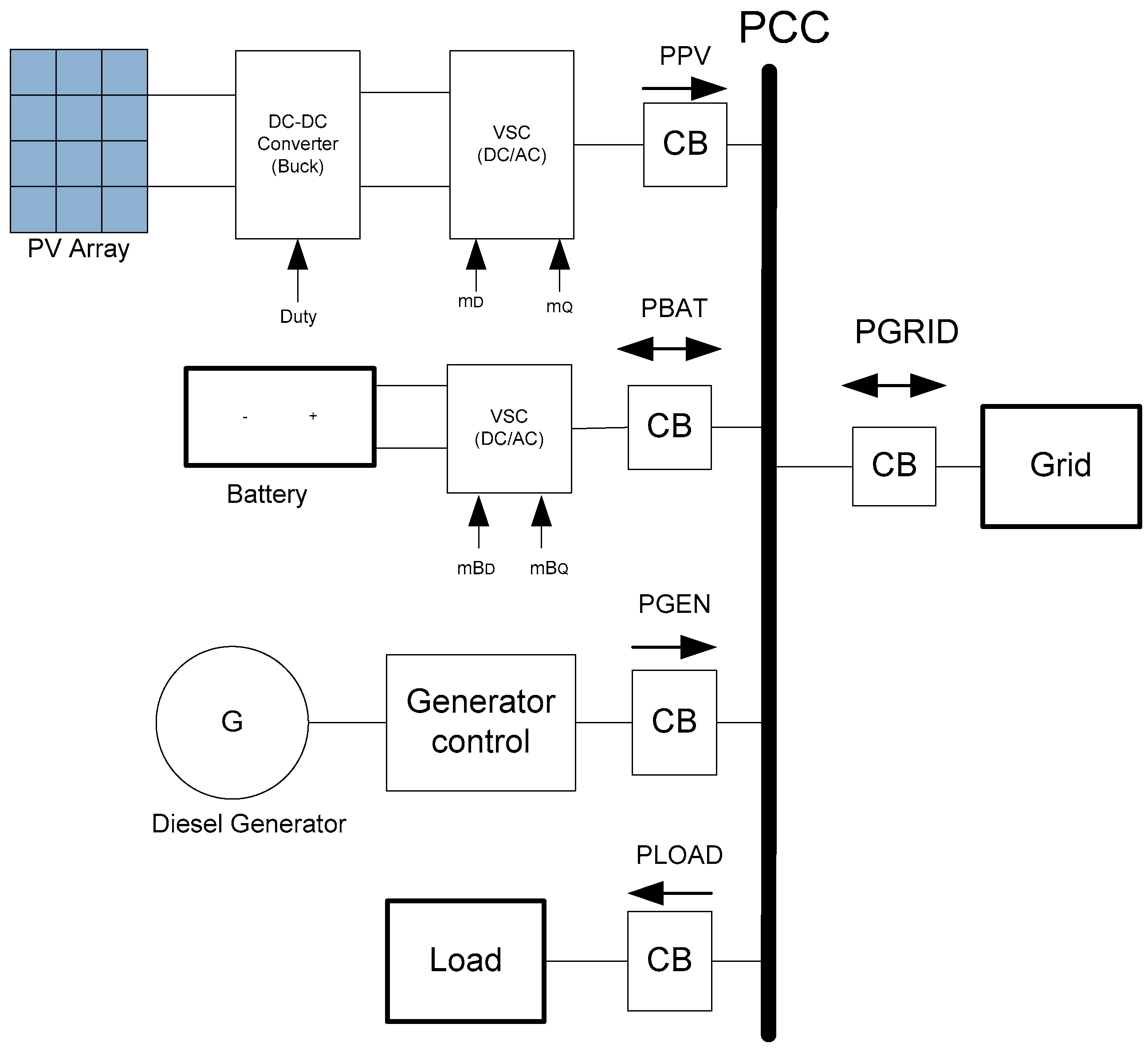
The proposed PV, battery, diesel generator and active load based microgrid system is shown in Figure 1. An inverter is employed to connect the PV array generated power to the grid. The PV and battery controls are based on the decoupled d-q current control strategy. The DERs and the grid are connected at the point of common coupling (PCC) using a circuit breaker (CB). Dynamic models of the main components are developed using RSCAD (Interfacing software with RTDS). During normal operation the microgrid is connected to the grid and load is supplied by both the DERs and the grid. The voltage and frequency are maintained at the rated values by the grid. In island mode, the load is supplied by the DERs. The voltage and frequency during island mode are controlled by the diesel generator in isochronous mode. In the isochronous speed control mode, the speed will return to the original speed set-point after a load has been applied or rejected. This mode is used when a generator is operating on its own and is used to maintain the frequency at rated 60 Hz.
From Figure 1:
- PPV represents PV array generated power,
- PBAT is the charging and discharging power of the battery storage system,
- PGEN is the power generated from the diesel generator,
- PLOAD is the power drawn by the load,
- PGRID is the power exchanged between the main grid and the microgrid,
- Duty is the buck converter control signal,
- mD and mQ are the PV voltage source converter (VSC)control signals,
- mBD and mBQ are the battery VSC control signals,
- PCC is the point of common coupling,
- CB is circuit breaker.
3. Proposed Controller
An independent controller is proposed and implemented for each DER. For the PV array, a multistage topology of buck converter and VSC are used to transfer the generated power PPV to the PCC. An incremental conductance control method is implemented for the buck converter and a d-q controller is employed for the VSC to transfer the DC link power to the PCC. A similar d-q controller is proposed for the battery for charging and discharging to meet its objectives. The diesel generator supplies a constant active and reactive power during grid connected mode and maintains the voltage and frequency in the island mode, whereas the grid takes care of the voltage and frequency in grid connected mode.
3.1. PV MPPT Controller
Different maximum power point tracking (MPPT) methods are archived in the literature to generate the maximum power from the PV system under varying irradiation and temperature. This paper employs incremental conductance to track the maximum power from the PV array. In this method, the PV array voltage VPV is continuously adjusted under time varying temperature and irradiation until it reaches the Maximum Power Point (MPP). A PI controller is used for the buck converter to force the PV array work at the MPP. The error between the MPPT output voltage Vref is compared with the actual PV array voltage VPV to generate the duty control signal for the buck converter as depicted in Figure 2.
The parameters of the buck converter, the PV array and the specifications of the battery are provided in Table 1.
where, from Equation (1) and Figure 2:
- kP and kI are the proportional and integral constants of the PI controller,
- IPV and VPV are the PV cell output current and voltage respectively,
- VDC is the DC link voltage,
- Vref is the MPPT output voltage.
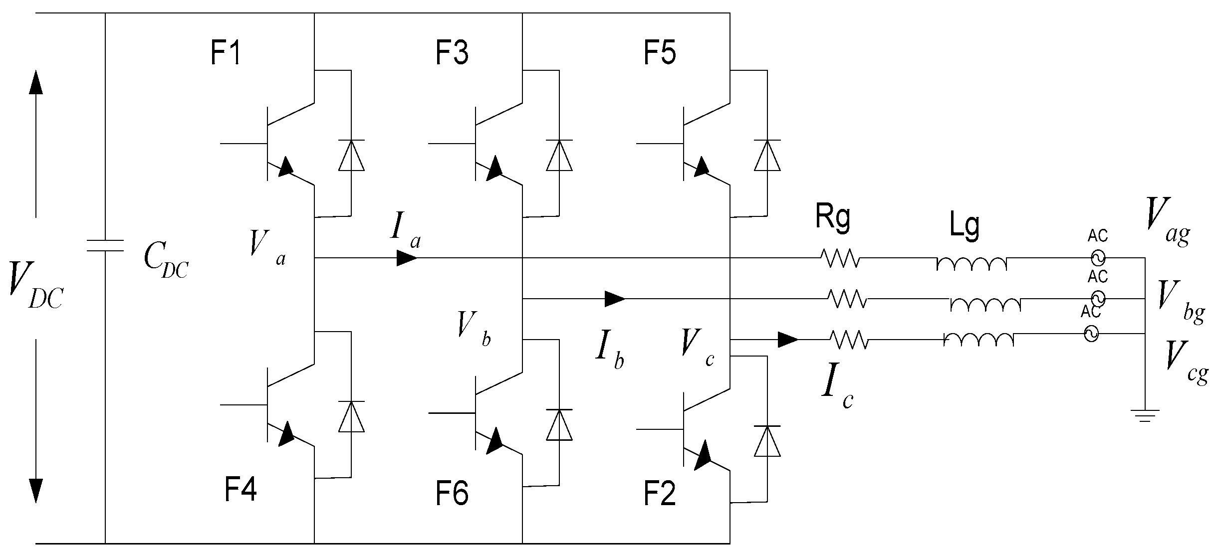
3.2. Decoupled d-q Controller for the PV VSC
The VSC shown in Figure 3 is used to integrate the PV DC link power to the PCC to supply AC loads and for grid integration.
The three phase voltage equations can be written as:
where,
- Ia, Ib and Ic are the grid side line currents,
- Va, Vb, Vc are the VSC output voltages,
- Vag, Vbg, Vcg are the grid voltages,
- Rg and Lg are resistance and inductance of the line.
Synchronous rotating reference frame (D-Q axis) based current control technique is implemented where the D current component ILD controls the active power flow and the Q current component ILQ the reactive power.
where,
- PG and QG are the grid side active and reactive power respectively,
- PDC is the DC link capacitor power,
Equation (3) can be further reduced to Equation (4) by aligning the D-axis reference frame to the phase voltage of the grid (VLQ = 0).
To improve the performance of the PI current controllers, feed forward voltage and cross-coupling terms are used as shown in Figure 4.
The outer voltage control loop in the Laplace frame is:
The D and Q-axes control signals in the Laplace domain are:
from Equations (5)–(7);
- kP’s are the proportional constants,
- kI’s are the integral constants,
- mD, and mQ are the PV array D and Q axes control signals respectively.
Pulse width modulation (PWM) is used to generate the firing pulses after converting mD and mQ back to ABC frame (DQ/ABC).
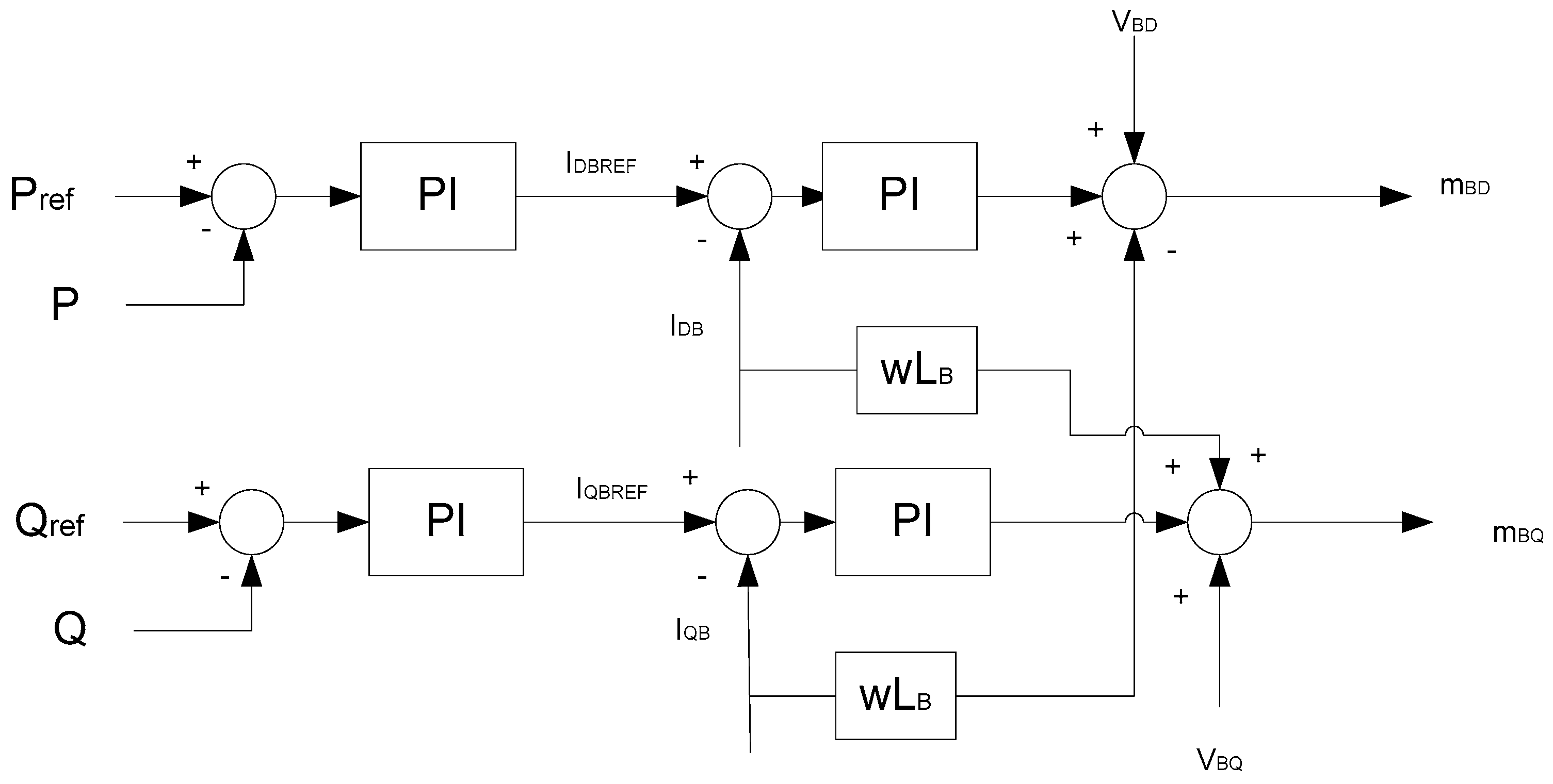
3.3. Battery Control
The battery controls are based on the decoupled d-q current control strategy. The battery is connected to the PCC using a VSC. During grid connected mode, the battery is controlled as a constant P-Q control to inject a constant active and reactive power to the PCC whereas during island mode, it is controlled in a voltage control mode to support the voltage and frequency. The battery controller for grid connected mode is provided in Figure 5. During island mode, the outer control loop is replaced by a voltage control loop with the reference voltage equal to the PCC voltage. The parameters of the battery are provided in Table 1.
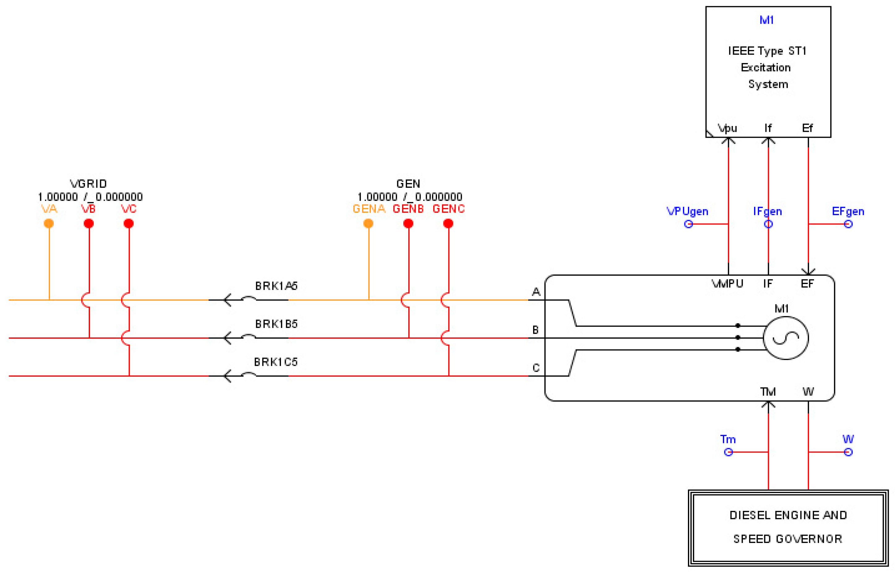
3.4. Diesel Generator Model and Control
In grid connected mode, the diesel generator provides real and reactive power and in islanded mode it regulates the microgrid frequency as shown in Figure 6. A synchronous machine with excitation system and a speed governor is used to model the diesel generator. The machine frequency is regulated by the speed governor driven by a diesel engine. Figure 7 shows the diesel engine and speed governor control where the inputs are diesel generator per unit speed ω and per unit speed reference ωref. The governor output is the per unit mechanical torque Tpu which drives the shaft of the synchronous generator. The diesel generator supplies specified reference power at grid frequency in speed-droop mode in grid connected operation, however, to control and maintain a constant frequency under varying load conditions in islanded operation; it is operated in isochronous mode. The parameters of the diesel generator are provided in Table 2.
4. Results and Discussion
The microgrid system developed in RTDS is presented in Figure 8. The specification of the PV array and the diesel generator are provided in Table 1 and Table 2 respectively. As given in Table 1, 1000 W/m2 and 25 °C were used as a reference solar intensity and temperature respectively. The operating voltage VMP and current IMP at the MPP are 2001 V (=115 × 17.4 V), and 201.3 A (=66 × 3.05 A), respectively. At this operating point, 402.8 kW (2001 V × 201.3 A) is the expected maximum output power from this PV array. The buck dc-dc converter converts the PV array terminal voltage (2 kV) to 1.62 kV as a common DC link voltage which is input to the PV array VSC to be converted to AC.
The following tests were applied to demonstrate the effectiveness of the proposed controllers.
- Grid connected mode (normal operation): The performance of the controller was tested by varying the load, irradiation and charging and discharging set points of the battery.
- Island mode: The controller was tested by varying the PV array irradiation, battery and load set points.
- Fault ride-through: The diesel generator capability in maintaining the frequency after a three phase fault was tested.
4.1. Grid Connected Mode (Normal Operation)
In this scenario, both the grid and the micrigrid operate in parallel. Initially the load is supplied by the grid and the DERs were off. When the switches of the DERs are on, the load will be supplied by both the grid and the DERs. The reference load power is set to 0.5 MW and the irradiation of the PV array is set at 1000 W/m2 meaning that the PV array generates around 0.4 MW. The battery is being charged with a reference power set point of 0.3 MW. For this particular case, the PV array power charges the battery and the remaining power supplies the load. The difference load power is provided by the grid. The diesel generator generates no output power as the difference comes from the grid. Figure 9 shows the corresponding grid power PGRID, the PV power PPV, the battery power PBAT, the diesel generator power PGEN and the load power PLOAD. As observed, the PV array generates the maximum available power to charge the battery. The controller manages the power balance with the grid matching the load power demand. The corresponding PCC voltage provided in Figure 10 is kept at its rated value. The state of charge (SOC) of the battery is presented in Figure 11. If the battery gets discharged (with 0.3 MW reference power), the grid power decreases by the same amount as presented in Figure 12. If the load is increased (from 0.5 to 1 MW), the grid power increases to accommodate the difference as depicted in Figure 13. If the irradiation increases from 1000 to 1200 W/m2, the grid power decreases accordingly, as shown in Figure 14.
The simulation results show that the DGs supply approximately the maximum active power and zero reactive power since they are designed to operate at unity power factor during normal operation.
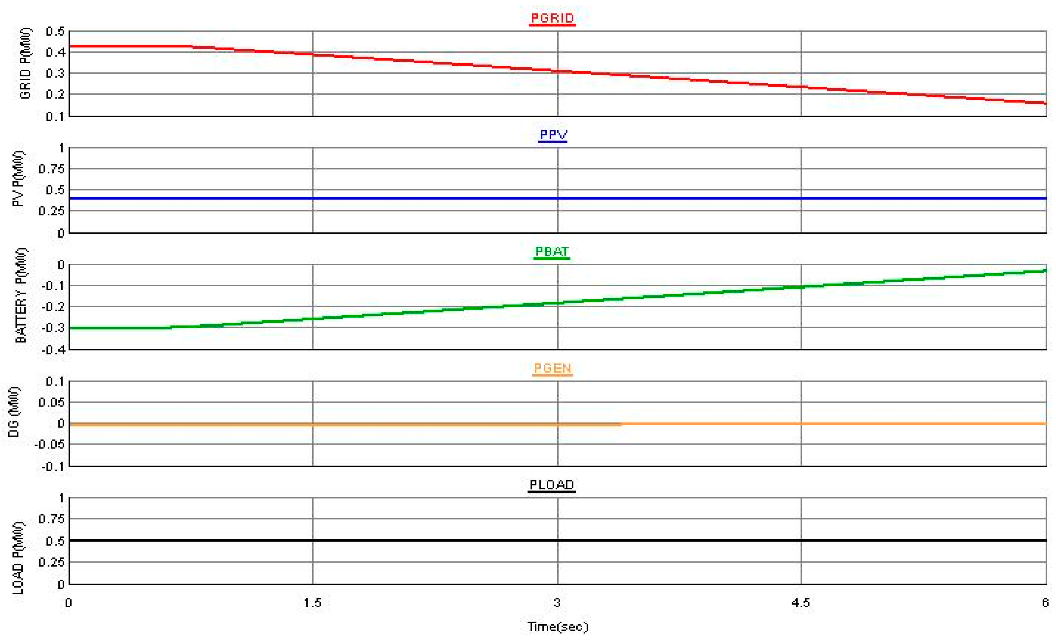
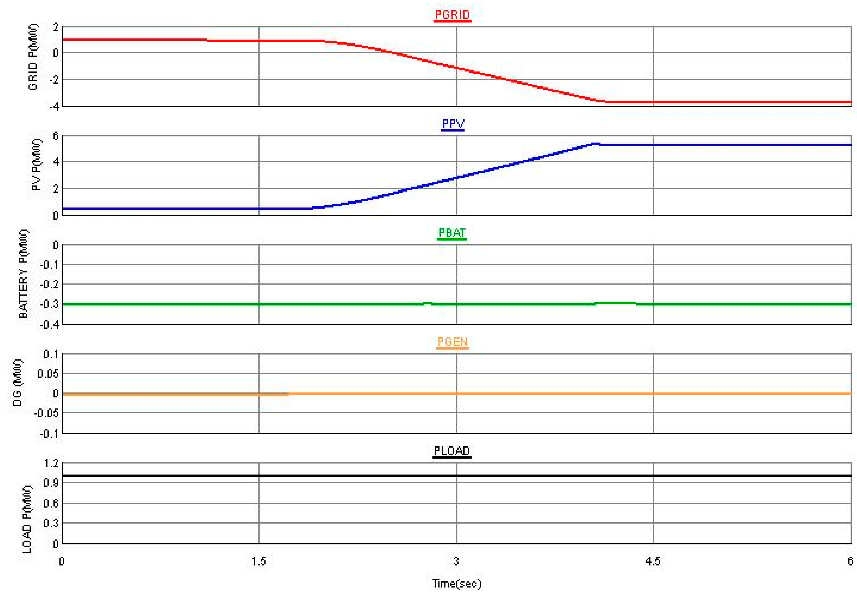
4.2. Island Mode
The controller’s capability was further tested in island mode. The system was working in grid connected mode with irradiation of 1000 W/m2 and the battery getting charged with PREF = −0.3 MW. Turning the grid side circuit breaker from Figure 1 off makes the system work in island mode. The diesel generator emulates the function of the grid and balances the load demand in island mode as depicted in Figure 15. As shown in the figure, the load is completely supplied by the DERs as the grid power is reduced to zero. The corresponding PCC voltage provided in Figure 16 is maintained at the rated value. Another scenario is applied by varying the PV array irradiation. When the PV irradiation decreases from 1000 to 500 W/m2, the diesel generator power increases to accommodate the difference as shown in Figure 17. With the same scenario, if the battery discharges (from −0.3 to 0.3), the diesel generator power decreases as shown in Figure 18.
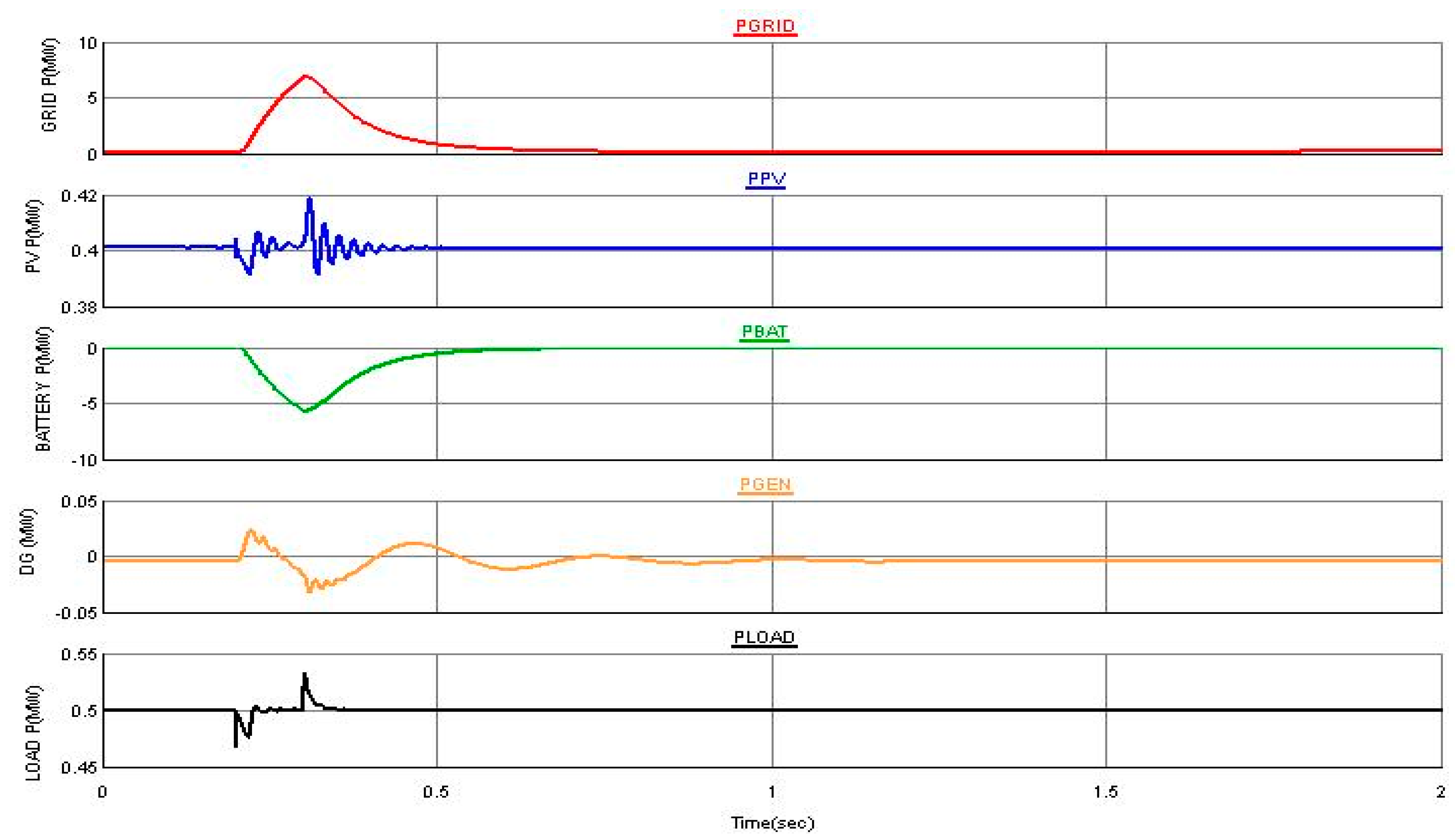
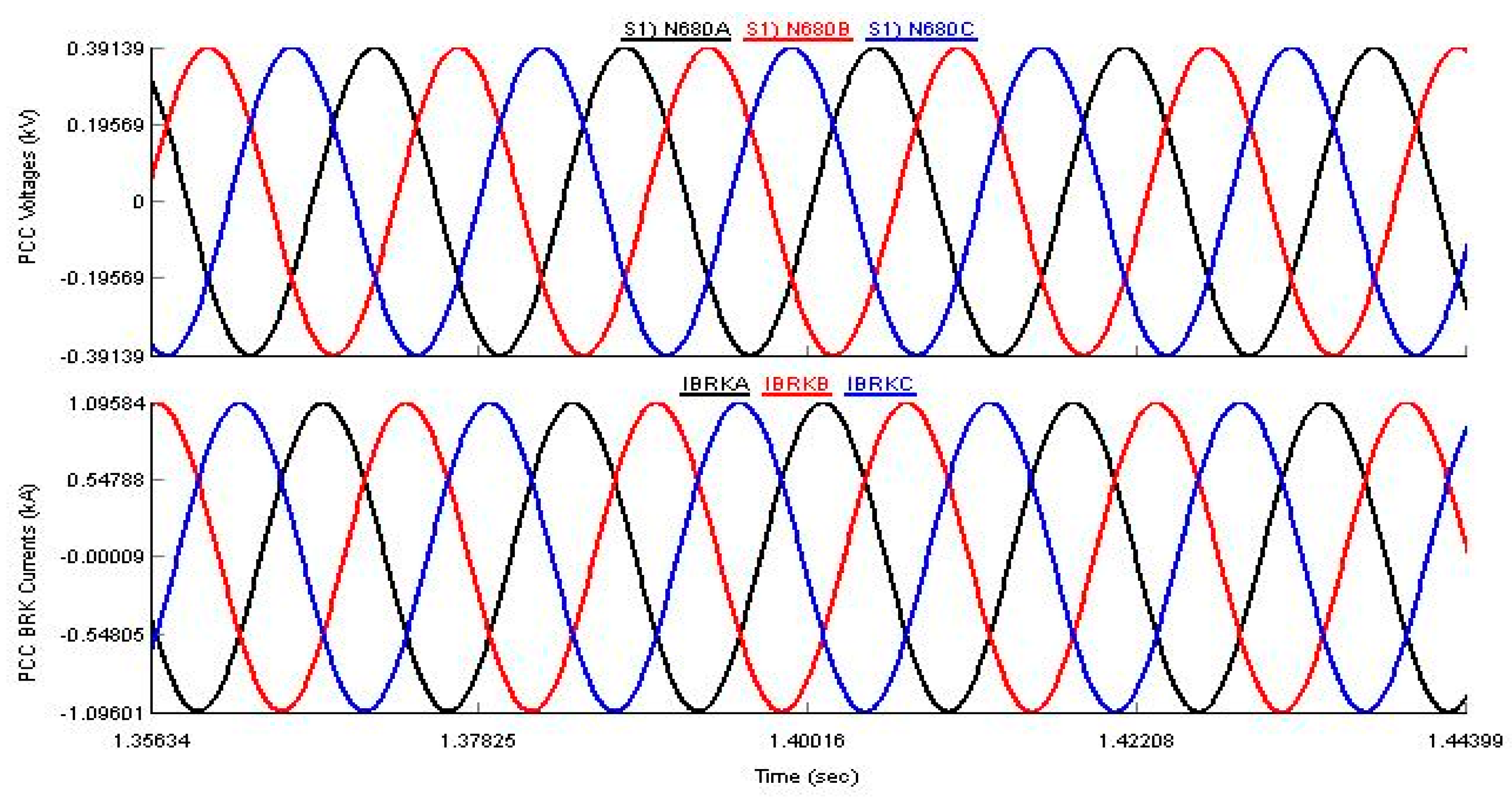
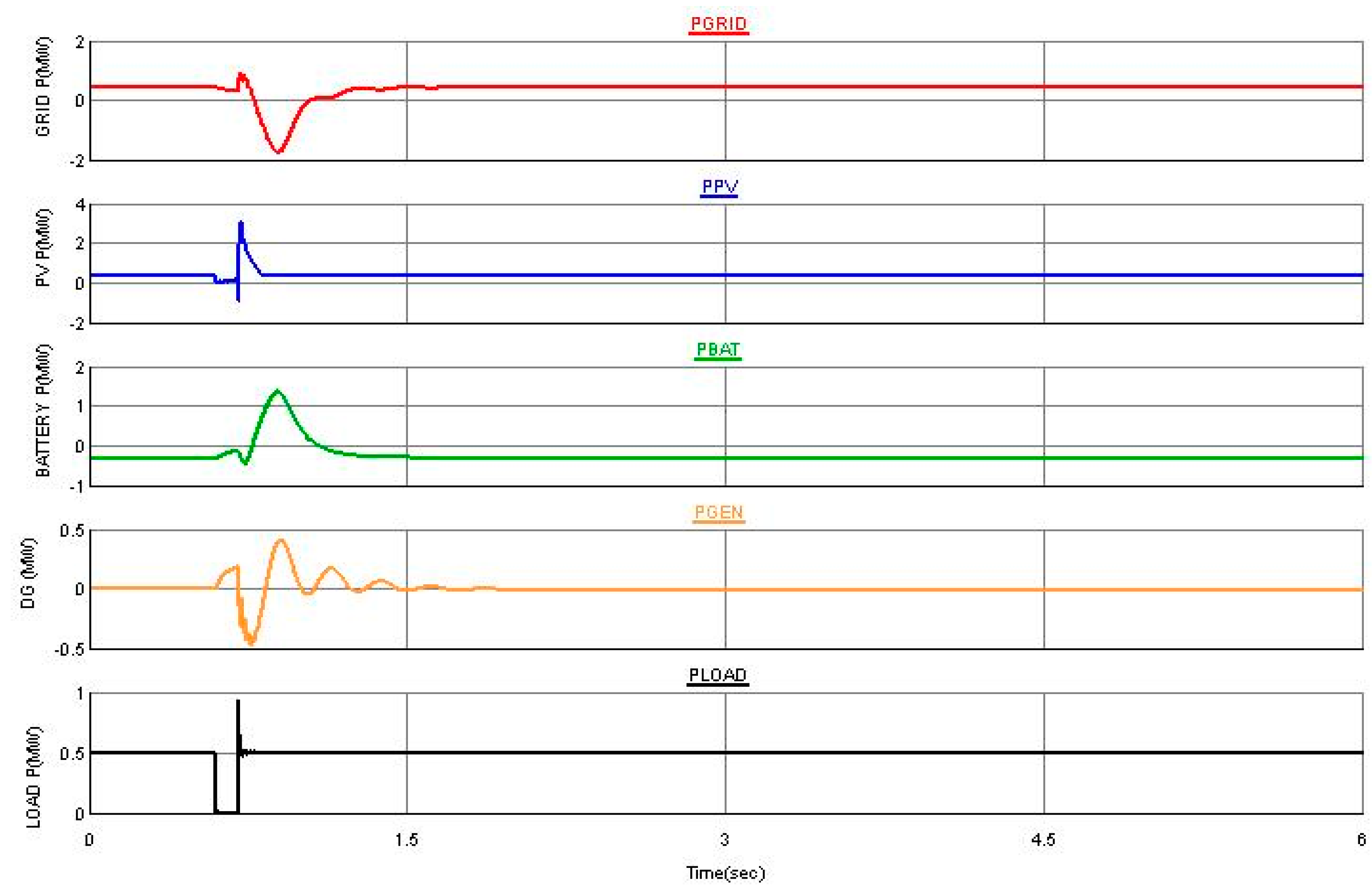
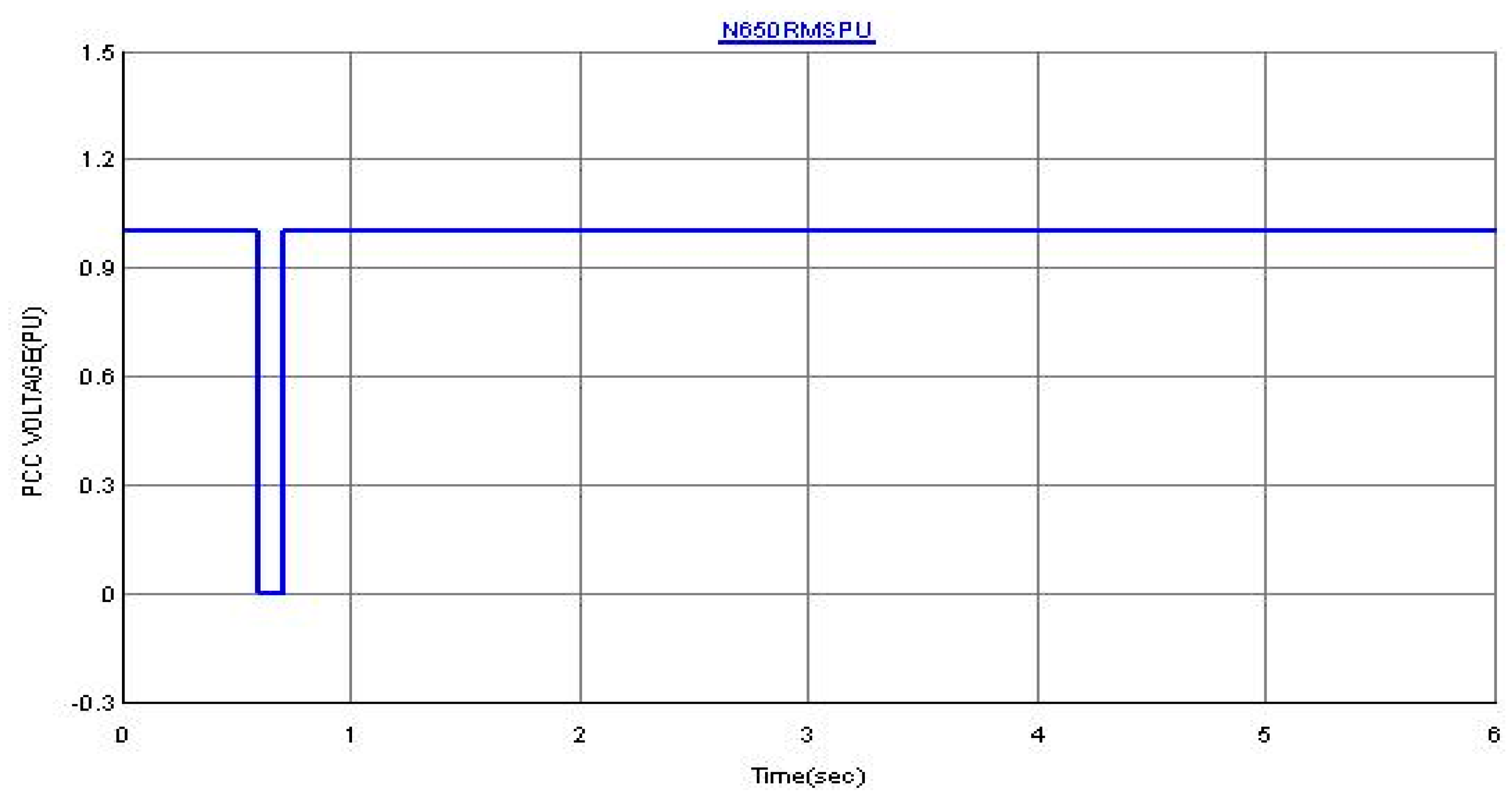
4.3. Fault Ride-Through
In order to further test the robustness of the controller, a three phase fault of six cycles was applied during grid connected and island modes of operation. The PCC voltage depicted in Figure 19 shows that the system has ridden through the fault. Figure 20 presents the corresponding grid, PV, battery, diesel generator and load powers during the grid fault. The response of the system during a six cycle fault in the island mode is presented in Figure 21 and Figure 22. In both grid connected and island modes, the system has recovered from the faults. The battery energy storage system helps the microgrid ride-through the fault.
5. Conclusions
An efficient power management control scheme of a microgrid based on PV, battery, diesel generator and load was presented in this paper. An independent P-Q controller is implemented to transfer the PV array and the battery powers to both the PCC and to the load. The incremental conductance based MPPT implemented forces the PV array to work at the maximum power. The system voltage and frequency are maintained at the rated value by the grid during grid connected mode and by the diesel generator in the island mode. The transient and steady state response of the microgrid for both grid-connected and islanded modes of operation have shown to give satisfactory performance. With energy storage, the fault ride-through capability of the system was improved. The results show that the proposed control scheme manages the load power during island and grid connected modes and improves the system reliability.
Author Contributions
M.Y.W. and M.A.A. initiated the idea and designed the controller. M.A.H. and the other authors performed the simulation and discussion.
Acknowledgments
The authors acknowledge the support provided by the Deanship of Scientific Research, King Fahd University of Petroleum and Minerals, through Electrical Power and Energy Systems Research Group Funded Project #RG171002.
Conflicts of Interest
The authors declare no conflict of interest.
References
- Parhizi, S.; Lotfi, H.; Khodaei, A.; Bahramirad, S. State of the Art in Research on Microgrids: A Review. IEEE Access 2015, 3. [Google Scholar] [CrossRef]
- Guerrero, J.M.; Loh, P.C.; Lee, T.L.; Chandorkar, M. Advanced Control Architectures for Intelligent Microgrids—Part II: Power Quality, Energy Storage, and AC/DC Microgrids. IEEE Trans. Ind. Electron. 2013, 60, 1263–1270. [Google Scholar] [CrossRef] [Green Version]
- Xia, Y.; Wei, W.; Yu, M.; Wang, X.; Peng, Y. Power Management for a Hybrid AC/DC Microgrid with Multiple Subgrids. IEEE Trans. Power Electron. 2018, 33, 3520–3533. [Google Scholar] [CrossRef]
- Radwan, A.A.A.; Mohamed, Y.A.R.I. Networked Control and Power Management of AC/DC Hybrid Microgrids. IEEE Syst. J. 2017, 11, 1662–1673. [Google Scholar] [CrossRef]
- Sahoo, S.K.; Sinha, A.K.; Kishore, N.K. Control Techniques in AC, DC, and Hybrid AC–DC Microgrid: A Review. IEEE J. Emerg. Sel. Top. Power Electron. 2018, 6, 738–759. [Google Scholar] [CrossRef]
- M, J.; Wang, Y.; Wang, C.; Wang, H. Design and implementation of hardware-in the-loop simulation system for testing control and operation of DC microgrid with multiple distributed generation units. IET Gener. Transm. Distrib. 2016, 11, 3065–3072. [Google Scholar] [CrossRef]
- Li, Z.; Shahidehpour, M.; Aminifar, F.; Alabdulwahab, A.; Al-Turki, Y. Networked Microgrids for Enhancing the Power System Resilience. Proc. IEEE 2017, 105, 1289–1310. [Google Scholar] [CrossRef]
- Jap, L.; Moreira, C.L.; Madureira, A.G. Defining Control Strategies for MicroGrids Islanded Operation. IEEE Trans. Power Syst. 2006, 21, 916–924. [Google Scholar] [CrossRef] [Green Version]
- Che, L.; Shahidehpour, M.; Alabdulwahab, A.; Al-Turki, Y. Hierarchical Coordination of a Community Microgrid with AC and DC Microgrids. IEEE Trans. Smart Grid 2015, 6, 3042–3051. [Google Scholar] [CrossRef]
- Nutkani, I.U.; Meegahapola, L.; Andrew, L.P.C.; Blaabjerg, F. Autonomous Power Management for Interlinked AC-DC Microgrids. CSEE J. Power Energy Syst. 2018, 4, 11–18. [Google Scholar] [CrossRef]
- Peyghami, S.; Mokhtari, H.; Blaabjerg, F. Autonomous Power Management in LVDC Microgrids Based on a Superimposed Frequency Droop. IEEE Trans. Power Electron. 2018, 33, 5341–5350. [Google Scholar] [CrossRef] [Green Version]
- Xin, H.; Zhang, L.; Wang, Z.; Gan, D.; Wong, K.P. Control of Island AC Microgrids Using a Fully Distributed Approach. IEEE Trans. Smart Grid 2015, 6, 943–945. [Google Scholar] [CrossRef]
- Hassan, M.A.; Worku, M.Y.; Abido, M.A. Optimal Design and Real Time Implementation of Autonomous Microgrid Including Active Load. Energies 2018, 11, 1109. [Google Scholar] [CrossRef]
- Dhua, R.; Chatterjee, D.; Goswami, S.K. Study of Improved Load Sharing Methodologies for Distributed Generation Units Connected in a Microgrid. CSEE J. Power Energy Syst. 2017, 3, 311–320. [Google Scholar] [CrossRef]
- Han, H.; Hou, X.; Yang, J.; Wu, J.; Su, M.; Guerrero, J.M. Review of Power Sharing Control Strategies for Islanding Operation of AC Microgrids. IEEE Trans. Smart Grid 2016, 7, 200–215. [Google Scholar] [CrossRef] [Green Version]
- Ou, T.; Hong, C. Dynamic operation and control of microgrid hybrid power systems. Energy 2014, 66, 314–323. [Google Scholar] [CrossRef]
- Ma, T.; Cintuglu, M.H.; Mohammed, O.A. Control of a hybrid AC/DC microgrid involving energy storage and pulsed loads. IEEE Trans. Ind. Appl. 2017, 53, 567–575. [Google Scholar] [CrossRef]
- Sharma, R.K.; Mishra, S. Dynamic Power Management and Control of a PV PEM Fuel-Cell-Based Standalone ac/dc Microgrid Using Hybrid Energy Storage. IEEE Trans. Ind. Appl. 2018, 54, 526–538. [Google Scholar] [CrossRef]
- Zheng, Y.; Li, S.; Tan, R. Distributed Model Predictive Control for On-Connected Microgrid Power Management. IEEE Trans. Control Syst. Technol. 2018, 26, 1028–1039. [Google Scholar] [CrossRef]
- Katiraei, F.; Iravani, M.R. Power Management Strategies for a Microgrid with Multiple Distributed Generation Units. IEEE Trans. Power Syst. 2006, 21, 1821–1831. [Google Scholar] [CrossRef]
- Nejabatkhah, F.; Li, Y.W. Overview of Power Management Strategies of Hybrid AC/DC Microgrid. IEEE Trans. Power Electron. 2015, 30, 7072–7089. [Google Scholar] [CrossRef]
- Eghtedarpour, N.; Farjah, E. Power Control and Management in a Hybrid AC/DC Microgrid. IEEE Trans. Smart Grid 2014, 5, 1494–1505. [Google Scholar] [CrossRef]
- Sun, Q.; Zhou, J.; Guerrero, J.M.; Zhang, H. Hybrid Three-Phase/Single-Phase Microgrid Architecture with Power Management Capabilities. IEEE Trans. Power Electron. 2015, 30, 5964–5977. [Google Scholar] [CrossRef]
- Worku, M.Y.; Abido, M.A.; Iravani, R. Power Fluctuation Minimization in Grid Connected PV Using Supercapacitor Energy Storage System. J. Renew. Sustain. Energy 2016, 8, 013501. [Google Scholar] [CrossRef]
- Jia, K.; Chen, Y.; Bi, T.; Lin, Y.; Thomas, D.; Sumner, M. Historical-Data-Based Energy Management in a Microgrid With a Hybrid Energy Storage System. IEEE Trans. Ind. Inform. 2017, 13, 2597–2605. [Google Scholar] [CrossRef] [Green Version]
- Tan, X.G.; Li, Q.M.; Wang, H. Advances and trends of energy storage technology in micro-grid. Int. J. Electr. Power Energy Syst. 2013, 44, 179–191. [Google Scholar] [CrossRef]
- Hill, C.A.; Such, M.C.; Chen, D.; Gonzalez, J.; Grady, W.M. Battery Energy Storage for Enabling Integration of Distributed Solar Power Generation. IEEE Trans. Smart Grid 2012, 3, 850–857. [Google Scholar] [CrossRef]
- Worku, M.Y.; Abido, M.A. Fault Ride-Through and Power Smoothing Control of PMSG-Based Wind Generation Using Supercapacitor Energy Storage System. Arab. J. Sci. Eng. 2018. [Google Scholar] [CrossRef]
- Kotra, S.; Mishra, M.K. A Supervisory Power Management System for a Hybrid Microgrid with HESS. IEEE Trans. Ind. Electron. 2017, 64, 3640–3649. [Google Scholar] [CrossRef]
- Korad, N.; Mishra, M.K. Grid Adaptive Power Management Strategy for an Integrated Microgrid with Hybrid Energy Storage. IEEE Trans. Ind. Electron. 2017, 64, 2884–2892. [Google Scholar] [CrossRef]
- Kumar, M.; Srivastava, S.C.; Singh, S.N. Control strategies of a DC microgrid for grid connected and islanded operations. IEEE Trans. Smart Grid 2015, 6, 1588–1601. [Google Scholar] [CrossRef]
- Mehrasa, M.; Pouresmaeil, E.; Sepehr, A.; Pournazarian, B.; Marzband, M.; Catalão, J.P.S. Control technique for the operation of grid-tied converters with high penetration of renewable energy resources. Electr. Power Syst. Res. 2019, 166, 18–28. [Google Scholar] [CrossRef]
- Marzband, M.; Azarinejadian, F.; Savaghebi, M.; Pouresmaeil, E.; Guerrero, J.M.; Lightbody, G. Smart transactive energy framework in grid-connected multiple home microgrids under independent and coalition operations. Renew. Energy 2018, 126, 95–106. [Google Scholar] [CrossRef]
- Marzband, M.; Fouladfar, M.H.; Akorede, M.F.; Lightbody, G.; Pouresmaeil, E. Framework for smart transactive energy in home-microgrids considering coalition formation and demand side management. Sustain. Cities Soc. 2018, 40, 136–154. [Google Scholar] [CrossRef]
- Tavakoli, M.; Shokridehaki, F.; Akorede, M.F.; Marzband, M.; Vechiu, I.; Pouresmaeil, E. CVaR-based energy management scheme for optimal resilience and operational cost in commercial building microgrids. Electr. Power Energy Syst. 2018, 100, 1–9. [Google Scholar] [CrossRef]
- Mahmood, H.; Jiang, J. Decentralized Power Management of Multiple PV, Battery, and Droop Units in an Islanded Microgrid. IEEE Trans. Smart Grid 2018. [Google Scholar] [CrossRef]
- Karimi, Y.; Oraee, H.; Guerrero, J.M. Decentralized Method for Load Sharing and Power Management in a Hybrid Single/Three-Phase-Islanded Microgrid Consisting of Hybrid Source PV/Battery Units. IEEE Trans. Power Electron. 2017, 32, 6135–6144. [Google Scholar] [CrossRef]
Figure 1.
The studied distributed energy resources (DER)based microgrid system.

Figure 2.
Maximum power point tracking (MPPT) and buck converter controller.

Figure 3.
Voltage source converter (VSC) for the PV source.

Figure 4.
Decoupled P-Q inverter control.

Figure 5.
Battery grid connected decoupled controller.

Figure 6.
Diesel generator, exciter and speed governor.

Figure 7.
Diesel generator speed governor controller.

Figure 8.
The studied DERs system model built in RSCAD (Interfacing software with RTDS).

Figure 9.
Grid power PGRID, PV array output power PPV, battery power PBAT, generator power PGEN and load power PLOAD.
Figure 9.
Grid power PGRID, PV array output power PPV, battery power PBAT, generator power PGEN and load power PLOAD.

Figure 10.
The corresponding grid voltage and breaker currents.

Figure 11.
State of charge (SOC) of the battery.

Figure 12.
Grid power PGRID, PV array output power PPV, battery power PBAT, generator power PGEN and load power PLOAD.
Figure 12.
Grid power PGRID, PV array output power PPV, battery power PBAT, generator power PGEN and load power PLOAD.

Figure 13.
Grid power PGRID, PV array output power PPV, battery power PBAT, generator power PGEN and load power PLOAD.
Figure 13.
Grid power PGRID, PV array output power PPV, battery power PBAT, generator power PGEN and load power PLOAD.

Figure 14.
Grid power PGRID, PV array output power PPV and load power PLOAD.

Figure 15.
Grid power PGRID, PV array output power PPV, battery power PBAT, generator power PGEN and load power PLOAD.
Figure 15.
Grid power PGRID, PV array output power PPV, battery power PBAT, generator power PGEN and load power PLOAD.

Figure 16.
The corresponding point of common coupling (PCC) voltage.

Figure 17.
Grid power PGRID, PV array output power PPV, battery power PBAT, generator power PGEN and load power PLOAD.
Figure 17.
Grid power PGRID, PV array output power PPV, battery power PBAT, generator power PGEN and load power PLOAD.

Figure 18.
Grid power PGRID, PV array output power PPV, battery power PBAT, generator power PGEN and load power PLOAD.
Figure 18.
Grid power PGRID, PV array output power PPV, battery power PBAT, generator power PGEN and load power PLOAD.

Figure 19.
PCC pu voltage during grid fault.

Figure 20.
Grid power PGRID, PV array output power PPV, battery power PBAT, generator power PGEN and load power PLOAD during grid fault.
Figure 20.
Grid power PGRID, PV array output power PPV, battery power PBAT, generator power PGEN and load power PLOAD during grid fault.

Figure 21.
PCC pu voltage during island fault.

Figure 22.
Grid power PGRID, PV array output power PPV, battery power PBAT, generator power PGEN and load power PLOAD during island fault.
Figure 22.
Grid power PGRID, PV array output power PPV, battery power PBAT, generator power PGEN and load power PLOAD during island fault.


Table 1.
Photovoltaic (PV) panel, battery and other component parameters.
| Parameter | Value |
|---|---|
| PV Array and Buck converter | |
| Reference Temperature | 25 °C |
| Reference solar intensity | 1000 W/m2 |
| Series connected modules | 115 |
| Parallel connected Modules | 66 |
| Open circuit voltage | 21.7 V |
| Voltage at maximum power (VMP) | 17.4 V |
| Short Circuit current | 3.35 A |
| Current at maximum power (IMP) | 3.05 A |
| PV cells in each model | 36 |
| Coupling inductance L1 | 1.35 mH |
| DC link capacitor CDC | 80 mF |
| C1 | 10 mF |
| Converter switching frequency | 5 kHz |
| L1 | 5 mH |
| Battery | |
| capacity of a single cell | 0.85 AH |
| Initial state of charge in a single cell | 85% |
| Number of cells in series in a stack | 250 |
| Number of stacks in parallel | 250 |
| Battery state of charge (SOC) | ≥50% |
| Capacity fading factor | 0% |
Table 2.
Diesel generator parameters.
| Parameter | Value |
|---|---|
| Rated rms line to line voltage | 0.48 kV |
| Rated MVA of the machine | 1.25 MVA |
| Inertia constant | 1.7 |
| Stator resistance | 0.002 pu |
| Leakage reactance, Stator | 0.13 pu |
| Unsaturated reactance, d-axis | 1.7 pu |
| Unsaturated transient reactance, d-axis | 0.16 pu |
| Unsaturated sub-trans reactance, d-axis | 0.135 pu |
| Unsaturated transient open T constant, d-axis | 4.3 s |
| Unsaturated sub-transient open T constant, d-axis | 0.032 s |
| Unsaturated reactance, q-axis | 1.71 pu |
| Unsaturated transient reactance, q-axis | 0.228 pu |
| Unsaturated sub-trans reactance, q-axis | 0.2 pu |
| Unsaturated transient open T constant, q-axis | 0.85 s |
| Unsaturated sub-transient open T constant, q-axis | 0.05 s |
| Grid voltage | 0.48 kV |
© 2019 by the authors. Licensee MDPI, Basel, Switzerland. This article is an open access article distributed under the terms and conditions of the Creative Commons Attribution (CC BY) license (http://creativecommons.org/licenses/by/4.0/).
Share and Cite
MDPI and ACS Style
Worku, M.Y.; Hassan, M.A.; Abido, M.A. Real Time Energy Management and Control of Renewable Energy based Microgrid in Grid Connected and Island Modes. Energies 2019, 12, 276. https://doi.org/10.3390/en12020276
AMA Style
Worku MY, Hassan MA, Abido MA. Real Time Energy Management and Control of Renewable Energy based Microgrid in Grid Connected and Island Modes. Energies. 2019; 12(2):276. https://doi.org/10.3390/en12020276
Chicago/Turabian StyleWorku, Muhammed Y., Mohamed A. Hassan, and Mohamed A. Abido. 2019. "Real Time Energy Management and Control of Renewable Energy based Microgrid in Grid Connected and Island Modes" Energies 12, no. 2: 276. https://doi.org/10.3390/en12020276
Note that from the first issue of 2016, this journal uses article numbers instead of page numbers. See further details here.