Creep Behaviors of Methane Hydrate-Bearing Frozen Sediments


1
Key Laboratory of Ocean Energy Utilization and Energy Conservation of Ministry of Education, Dalian University of Technology, Dalian 116024, China
2
Department of Civil and Environmental Engineering, University of California, Berkeley, CA 94720, USA
*
Author to whom correspondence should be addressed.
Energies 2019, 12(2), 251; https://doi.org/10.3390/en12020251
Submission received: 30 November 2018
/
Revised: 28 December 2018
/
Accepted: 11 January 2019
/
Published: 15 January 2019
(This article belongs to the Section L: Energy Sources)
Abstract
:Creep behaviors of methane hydrate-bearing frozen specimens are important to predict the long-term stability of the hydrate-bearing layers in Arctic and permafrost regions. In this study, a series of creep tests were conducted, and the results indicated that: (1) higher deviator stress (external load) results in larger initial strain, axial strain, and strain rate at a specific elapsed time. Under low deviator stress levels, the axial strain is not large and does not get into the tertiary creep stage in comparison with that under high deviator stress, which can be even up to 35% and can cause failure; (2) both axial strain and strain rate of methane hydrate-bearing frozen specimens increase with the enhancement of deviator stress, the decrease of confining pressure, and the decrease of temperature; (3) the specimens will be damaged rather than in stable creep stage during creeping when the deviator stress exceeds the quasi-static strength of the specimens.
1. Introduction
Methane hydrate is an ice-like substance, in which methane (the main component of natural gas) is trapped within a cage structure composed of water molecules under low temperature and relatively high pressure conditions. Because enormous amounts of methane hydrate have been found in Arctic permafrost regions and in deep water sedimentary layers, methane hydrate is anticipated to be a potential energy resource in the near future. To date, more than a hundred dedicated methane hydrate research and exploration wells have been drilled to quantify methane hydrate occurrences, and the well offshore at eastern Nankai Trough, Japan, and Shenhu Area, Northern South China Sea, China, and in permafrost settings at Mallik, Canada, and Ignik Sikumi, Alaska, have field-tested production technologies [1,2,3], which represent numerous problems associated with methane hydrate, including casing failures, borehole breakage, stratum settlement, and deformation [4,5]. In view of the problems, the mechanical behaviors of methane hydrate-bearing layers should be clarified to assess the stability of the layers and the production well before methane hydrate commercial production [6].
To address this issue, a series of triaxial and plane compression tests were conducted to investigate the mechanical properties of methane hydrate-bearing sediments before, during, and after hydrate dissociation [7,8,9]. The results can be used to establish constitutive models [10] and calculate the deformation of the layers during hydrate production [11,12]. The primary mechanism of methane hydrate induced slope failure is that the dissociation of hydrate to free gas, resulting in a significant pore pressure increase and cementation loss in layers. However, Mountjoy et al. [13] presented evidence that, contrary to conventional views, the methane hydrate-bearing layers could exhibit creep deformation, and the methane hydrate can itself destabilize the layers. So far, only a few creep tests on methane hydrate-bearing sediments have been reported [14], even though the creep behaviors are important to predict the long-term stability of the layers.
Parameswaran et al. [15] preliminarily carried out creep tests on frozen sand containing tetrahydrofuran (THF) hydrate at 270 K, and the creep curves and creep rates under various axial stress were obtained. Cameron et al. [16] investigated the creep behaviors of THF hydrate-consolidated sands under uniaxial compression, and found that the hydrate-consolidated sands were much stronger than that of ice-consolidated sands [17]. However, the formation process (liquid-liquid), structure, and polarity of THF hydrate are quite different from that of methane hydrate, and there are some limitations in using THF hydrate instead of methane hydrate to study the mechanical properties [18]. Durham et al. [19] determined from creep tests on high-purity methane hydrate (structure I) that methane hydrate is more than 20 times stronger (creep resistant) than ice. Miyazaki et al. [14,20] conducted the drained triaxial compression creep tests on synthetic methane hydrate-bearing sand, and compared these with the strain rate dependence of strength in constant-strain-rate tests. The results showed that the methane hydrate-bearing sand specimen presented typical creep curves and had considerable time dependence, and the strain rate was inversely proportional to the m-th power of elapsed time and residual time at the beginning of creep test and before failure of the specimen, respectively. Also, Miyazaki et al. [21] proposed a nonlinear viscoelastic constitutive equation for methane hydrate-bearing sand based on the creep behaviors. Li et al. [22] conducted a series of creep tests on methane hydrate coexisting with ice, and the effects of deviator stress, confining pressure, and temperature on the creep behaviors were studied.
According to the literature [23,24,25,26], the methane hydrate found in Arctic and permafrost regions may coexist with ice. Durham et al. [19] suggested that the impurities, such as liquid water or ice in the specimen, would significantly influence the mechanical behaviors of methane hydrate-bearing sediments. As a result, it is essential to study the creep behaviors of methane hydrate-bearing frozen sediments (coexisting with ice) before the methane hydrate commercial production in Arctic and permafrost regions. In this paper, the effects of deviator stress, confining pressure, and temperature on the creep behaviors of methane hydrate-bearing frozen sediments were investigated, and the creep curves and isochronous stress-strain curves were obtained.
2. Experimental Methods
2.1. Experimental Apparatus
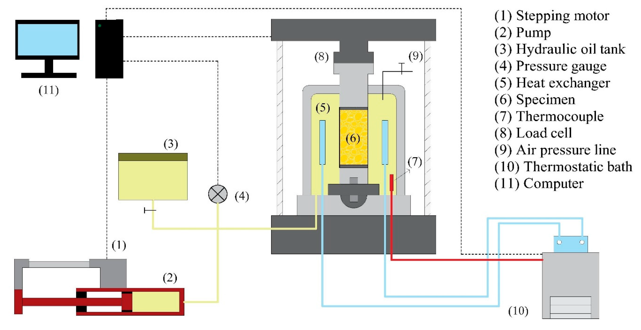
The experimental apparatus for creep tests is drawn schematically in Figure 1. It can simulate the in situ conditions (temperature, pressure, and stress) of hydrate-bearing layers in a cylindrical specimen with dimensions of φ50 × 100 mm. The axial load and confining pressure are digital servo-controlled with a maximum of 60 kN and 30 MPa (with an accuracy of ±0.3 MPa), respectively. The temperature inside the chamber ranges from −20 °C to 25 °C, with an accuracy of ±0.5 °C, which was controlled by the heat exchanger with circulating refrigerant liquid from a thermostatic bath. All the experimental data is recorded by the computer automatically during the test.
2.2. Experimental Procedure and Test Conditions
In this study, the kaolin clay was chosen as the host material, whose particle size is close to the sediments in Qilian Mountain permafrost, Qinghai-Tibet Plateau, China. The methane hydrate-bearing frozen specimen was prepared by a mixture method, where ice, methane hydrate, and kaolin clay are well mixed and molded, as shown below. Firstly, methane hydrate was formed by mixing ice powders (less than 250 μm in size) and methane gas with an initial pressure of 10 MPa in a high-pressure reaction chamber, which was placed in a refrigerator with a constant temperature of −10 °C. The reaction between ice powders and methane gas was considered to be complete when the pressure in the chamber was stable, which always takes about 48 h. In this way, the obtained methane hydrate was coexisted with ice powders, and the volume proportion of methane hydrate to ice was about 3/7. Secondly, a certain mass of methane hydrate-ice mixture (115.8 g) and dried kaolin clay (204.2 g) was well mixed by stirring, and then compacted in a pressure crystal device under an axial stress of 10 MPa and a temperature of −10 °C. The dimension of the obtained specimen was φ50 × 100 mm, the bulk density of the specimen was 1.63 g/cm3, and the volume ratio of kaolin clay to the solid phase of the specimen was 40%. Finally, the specimen was covered with a rubber membrane of 0.5 mm in thickness and moved onto the pedestal in the triaxial chamber for creep tests. In this study, the whole specimen preparation process was performed under a temperature of −10 °C in cold storage, with a purpose of minimizing the dissociation of methane hydrate.
A series of creep tests were performed on methane hydrate-bearing frozen specimens under undrained conditions at temperatures of −2.5, −5, −7.5, and −10 °C; confining pressures of 2.5, 5, 7.5, and 10 MPa; and deviator stresses of 0.5, 0.75, 1, 1.25, 2, 3, 4, and 5 MPa, as shown in Table 1. The strain rate was 1.0 mm/min before the designated axial load was reached.
3. Results and Discussion
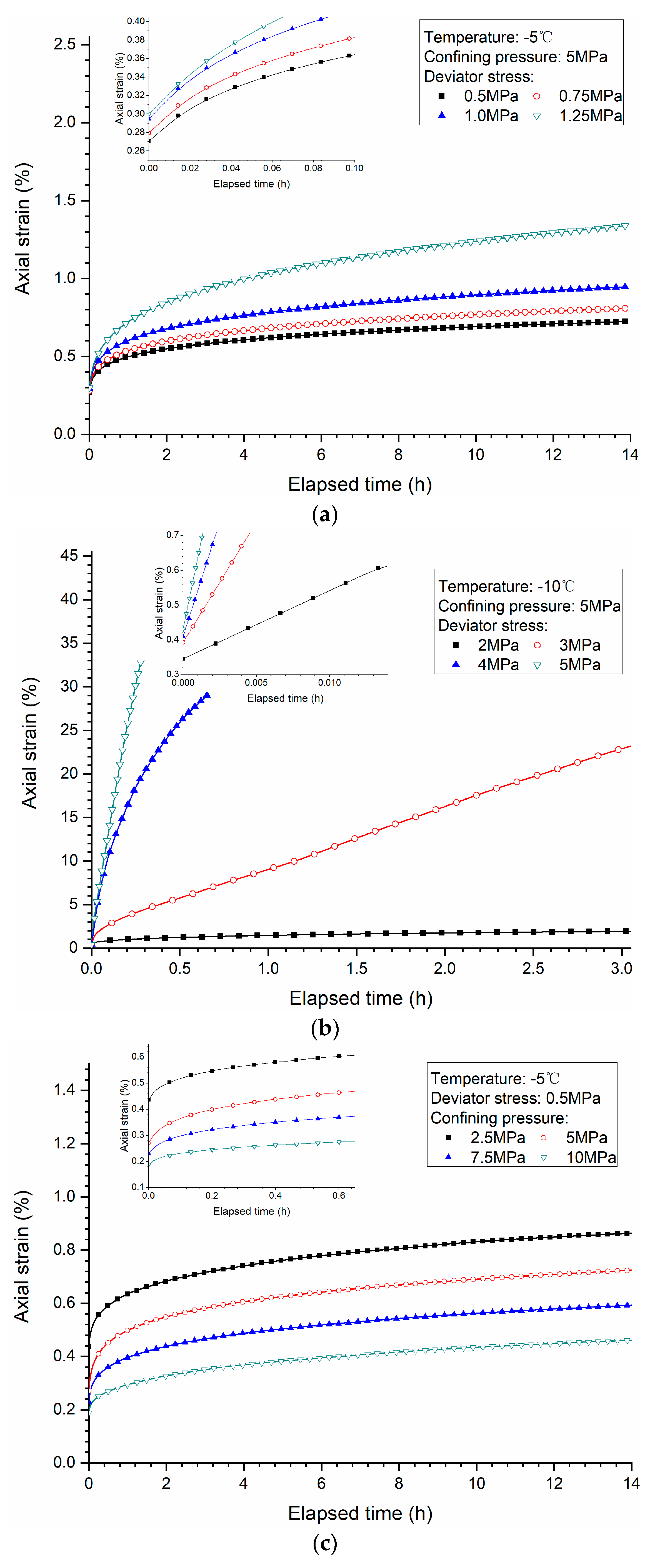
Creep is a phenomenon for solid material whereby the strain increases with elapsed time while the external stress remains unchanged. Unlike plastic deformation, which usually occurs after the stress exceeds the elastic limit, creep can occur even when the stress is less than the elastic limit, as long as the stress lasts for a considerable time. The creep process can be divided into three stages: the primary creep stage (or the initial creep stage), where the strain increases with elapsed time, but the strain rate slows down gradually; the secondary creep stage (or the steady-state creep stage), where the strain increases with elapsed time at an almost constant strain rate; and the tertiary creep stage (or the accelerating creep stage), where the strain increases with elapsed time rapidly and accelerates to failure directly. In this study, the point when axial load reaches the predetermined value was designated as the beginning of the creep curve. Figure 2a–d shows the relationships between the axial strain and the elapsed time for the methane hydrate-bearing frozen specimens under different low deviator stresses (Figure 2a), high deviator stresses (Figure 2b), confining pressures (Figure 2c), and temperatures (Figure 2d), respectively.
Unfortunately, none of the creep experiments ran to the tertiary creep stage (or the accelerating creep stage). Even for the specimens under high deviator stress levels, which are 4 MPa and 5 MPa, the specimens were just damaged directly without entering the tertiary creep stage, as shown in Figure 2b. The others were terminated prematurely, and experienced only two creep stages: the primary creep stage and the secondary creep stage. This is mainly caused by two points. In the first, the applied deviator stresses used in the creep tests were lower than the critical stress, so no matter how long it goes for, the material will not break down, or the creep time is infinite. This stress value is called the long-term strength of the material. Secondly, the tertiary creep stage just did not appear within the elapsed time in these tests.
As shown in Figure 2a,c,d, the creep behavior of methane hydrate-bearing frozen specimens is similar to that of THF hydrate-consolidated sand and methane hydrate-ice specimens [15,16,22]. The observed time dependent behavior comes from the time dependent properties, both of the ice and the hydrates, as it is known that the ice exhibits creep behavior as well as hydrates. In addition, comparing to the geomaterials without hydrate [14], the creep behavior of methane hydrate-bearing frozen sediment specimens presents more significant pressure and temperature dependence, since hydrate is a kind of metastable material which is sensitive to pressure and temperature. When the load is applied, the compression of cracks in the host specimen skeleton and the visco-plastic flow of hydrate and ice (i.e., the initial creep stage) will be the main behavior, and finally the slopes of the curves reach a constant value. It’s worth mentioning that the methane hydrate-bearing frozen specimens get into the secondary creep stage in a relatively short time compared with the methane hydrate-ice specimens in our previous work [22]. This is because there are more initial micro cracks in the clay-made specimen, since the filling effect of ice and hydrate should be generated in the primary stage. When the axial load is not high enough, along with the elapsed time, some micro cracks would generate, propagate, and unite, the creep of the soil skeleton and the visco-plastic flow of hydrate and ice would slow down correspondingly, and eventually the unstable cracks would propagate [14,27].
3.1. Effects of Deviator Stress
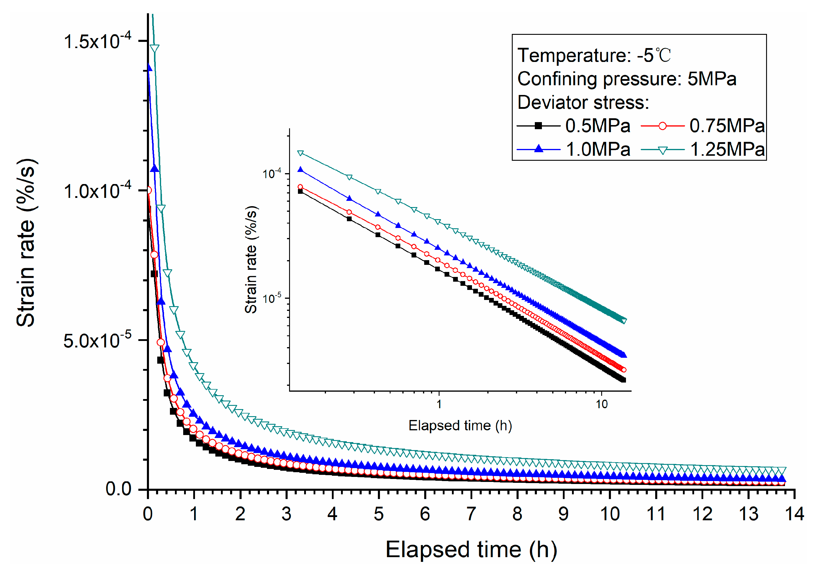
Figure 2a shows the creep curves of methane hydrate-bearing frozen specimens under low deviator stresses of 0.5 MPa, 0.75 MPa, 1.0 MPa, and 1.25 MPa, with confining pressure of 5 MPa and temperature of −5 °C. It can be observed that the deviator stress has an impact on the creep behavior of the specimens. Higher deviator stress results in a larger axial strain at a specific elapsed time for both the primary creep stage and secondary creep stage. The slope of the curve tends to be greater at the initial phase of the primary stage with higher deviator stress. That is, it takes longer time to reach the same value of axial strain for each specimen when the tests are conducted under lower deviator stress. This is because the higher deviator stress leads to more degradation of the cementing structure, making the deformation (axial strain) larger. The creep strain was not very large, which is less than 1.5% during the creep test, because the damage of specimens didn’t occur. Figure 3 shows the change of strain rate during the creeping of the specimen. As mentioned above, only two creep stages were detected. During the primary creep stage, axial strain changes fast at the beginning but slower with the proceeding of creep. Then, the strain rate stays nearly constant, meaning that the specimen was at the secondary stage. The reason why the strain rate decreases with the creeping time can be explained as the internal cementing structure adjustment. When the external load was exerted on the specimen, the internal skeleton structure, including cementing structure of the specimen, was damaged suddenly and locally, leading to a significant increase in the axial strain rate. Meanwhile, the local damage of the structure was healed with the skeleton structure readjustment under low external load, thus the creep strain rate exhibits attenuation behavior. When the damage enhancement and healing offset each other, the strain rate eventually remain constant. Similar creep behaviors of the sediments were discovered by Miyazaki et al. [20,27].
The stress conditions also influence the creep behaviors of the specimens. It is also shown in Figure 2a and Figure 3 that both strain and strain rate of the specimen under higher deviator stress are larger. Higher deviator stress, which responds to higher external load, generates more micro fractures in the specimen, weakens the skeleton structure, and deforms the specimen more. Much of the literature also observed a larger creep strain rate at higher deviator stress for frozen soil, pure methane hydrate, and THF/methane hydrate-sand specimens [16,19,27,28,29]. Moreover, the relationship between strain rate and elapsed time in the logarithmic coordinate system is also shown in Figure 3, where the slope approaches a constant value during creeping, and enhances with the increase of deviator stress, which means the strain rate of specimens under higher deviator stress was reduced more slowly. It is much more difficult to heal the local damage caused by the higher deviator stress, and it takes more time to reach the steady state as a result.
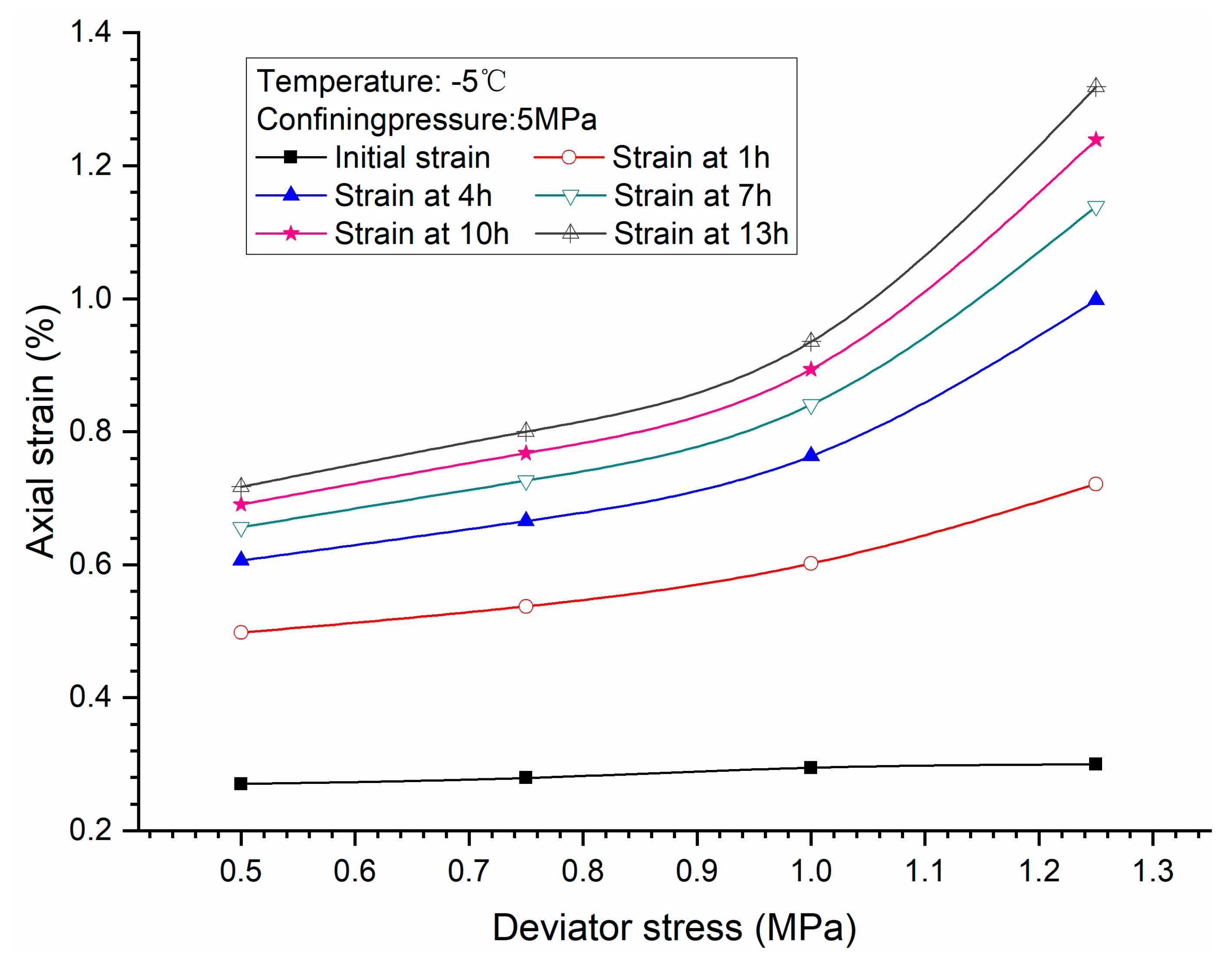
Similar to Figure 3, Figure 4 shows that the strain rate firstly decreases sharply and then gently with the increase of axial strain. The relationship between axial strain and strain rate is strongly dependent on the deviator stress. At the same state of axial strain, the strain rate of the specimen under high deviator stress is larger than that under low deviator stress. Moreover, the relationship between strain rate and axial strain in the logarithmic coordinate system is also shown in Figure 4, where the slope approaches a constant value eventually, which illustrates the strain rate decrease more slowly with axial strain under larger external load. Thus, higher deviator stress induces larger accumulated axial strain. That means at the same deformation state of control element, higher deviator stress results in more serious damage of the skeleton structure and higher creep deformation potential. As a result, greater strain rate can be obtained. It can be demonstrated clearly in Figure 5, which shows axial strain versus deviator stress at different elapsed times. At the beginning of creep, the difference of axial strain is not clear. However, with the creeping of specimens, higher deviator stress induced greater axial strain change.
Creep behaviors of specimens under high stress condition are different from the low stress condition, which has been described above. Figure 2b shows the creep curves of methane hydrate-bearing frozen specimens under different deviator stresses of 2.0 MPa, 3.0 MPa, 4.0 MPa, and 5.0 MPa, with confining pressure of 5 MPa, and temperature of −10 °C. The curves are straight at the initial phase of the primary stage under high stress condition. The axial strain of the specimen under higher deviator stress is larger and even up to nearly 35%. The damage to the skeleton structure was recovered and the failure of the specimen occurred during creeping tests when deviator stress of 4 MPa or above was applied.
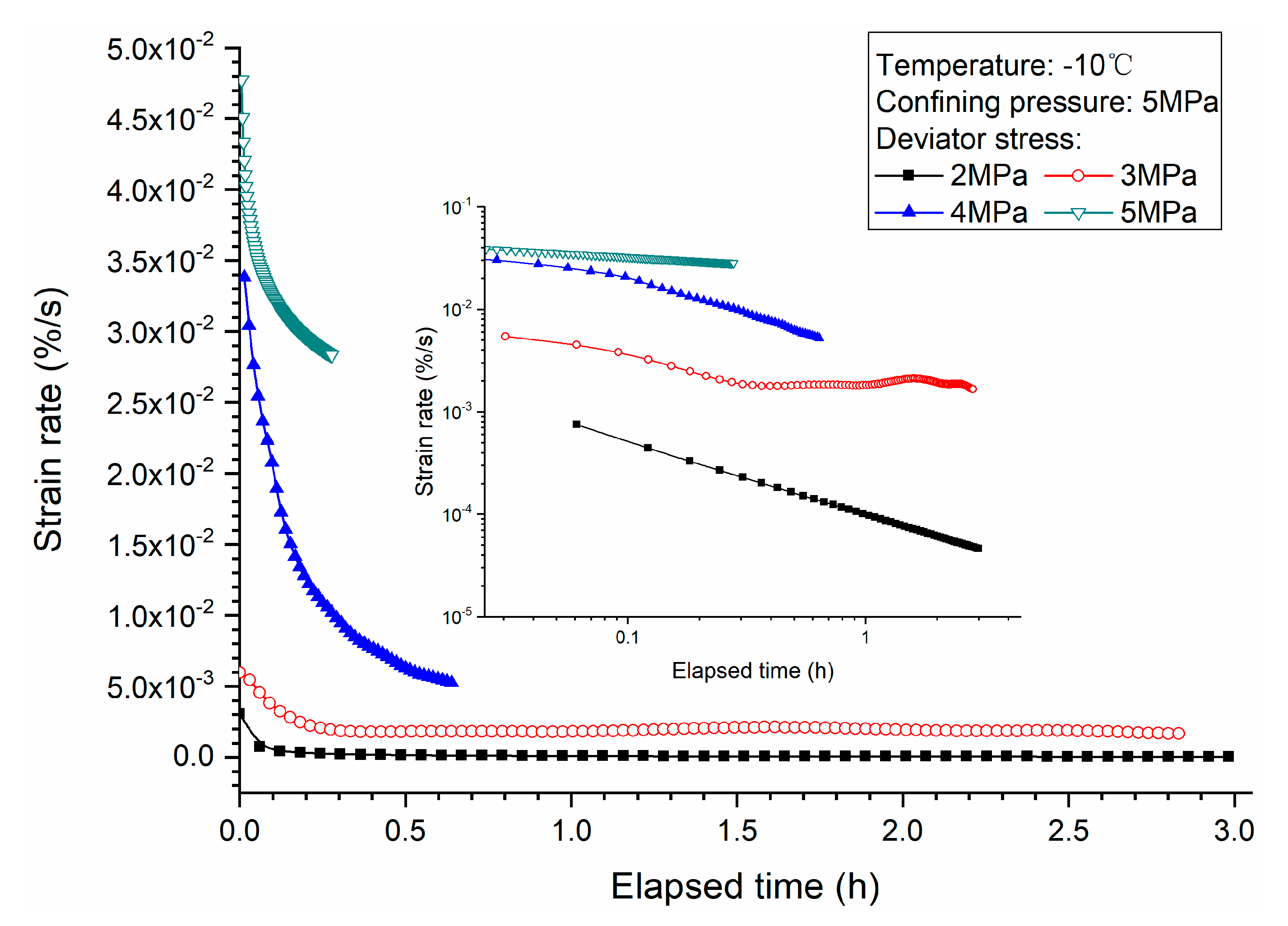
Figure 6 demonstrates the change of strain rate with the specimen creeping. For the cases of deviator stress of 2 MPa and 3 MPa, two creep stages can be detected, including the primary creep stage and the secondary stage. The strain rate increases fast at the beginning but slower during creeping. Finally, the strain rate keeps nearly constant, meaning that the specimen was at the secondary stage. In contrast, deviator stresses of 4 MPa and 5 MPa are so high that the axial deformation is too fast for the specimen, and unfortunately, the data of longer elapsed time were not obtained due to large deformation and failure of the specimens. Moreover, the relationship between strain rate and elapsed time in the logarithmic coordinate system is also shown in Figure 6, where the curve is no longer a stabilized descent straight line when the deviator is greater than 2 MPa. This is mainly due to the rapid instability of the internal structure. As discussed above, the reason why the strain rate decreases with the creeping time is due to the internal cementing structure adjustment. However here, the local damage of the structure cannot be healed with skeleton structure readjustment, and finally, damage took place when the deviator stress was greater than the shear strength of the specimen.
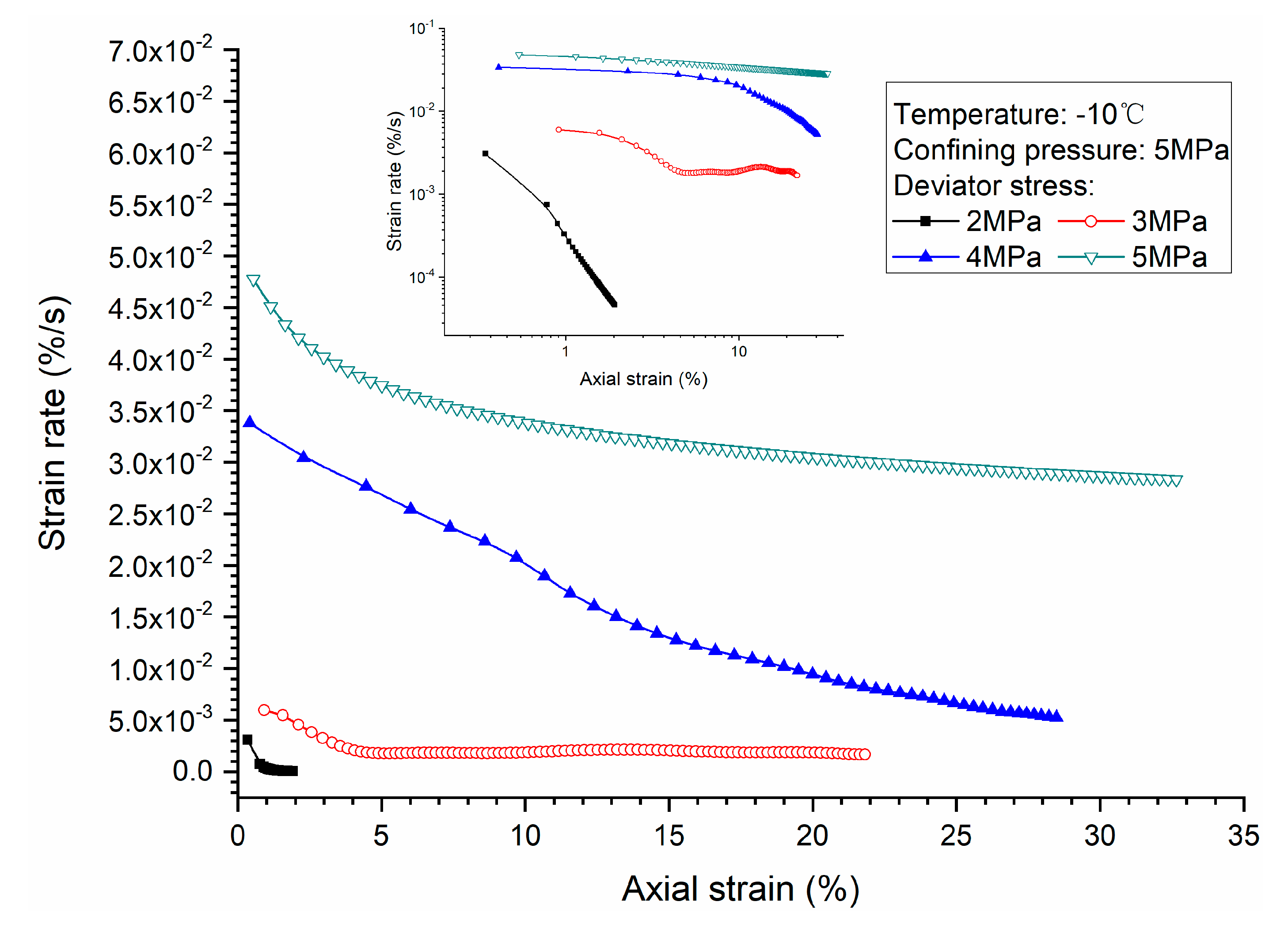
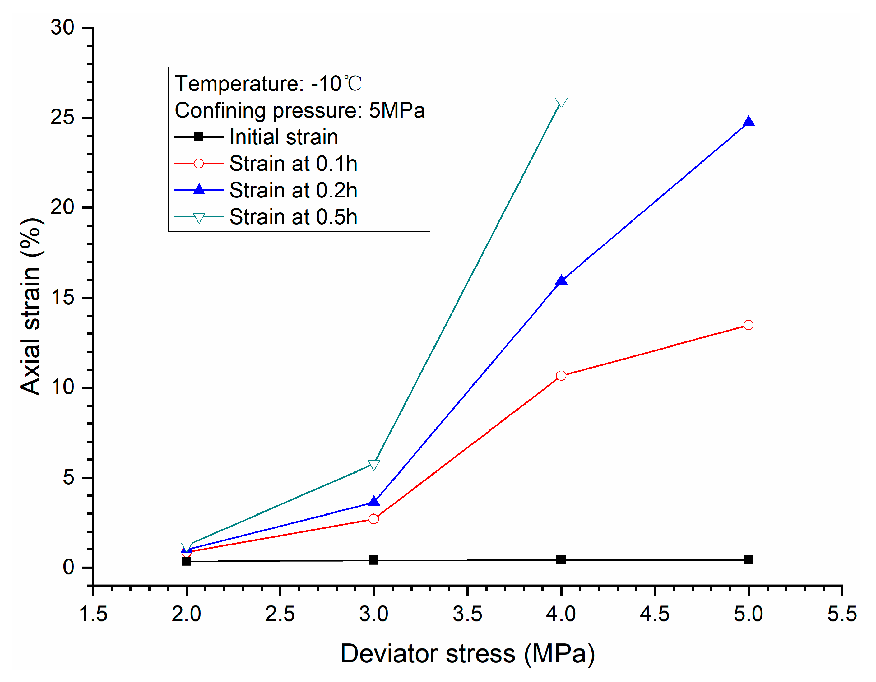
Figure 7 shows that the strain rate firstly decreases rapidly and then slowly with the increase of axial strain. In the cases of 2 MPa and 3 MPa, the axial strain rate remained constant after a period of time, but for the cases of 4 MPa and 5 MPa, the axial strain rate decreased until the specimens were damaged. The relationship between strain rate and axial strain in the logarithmic coordinate system is also shown in Figure 7, where the attenuation of strain rate varies with axial strain. The relationship between axial strain and strain rate is strongly dependent on the deviator stress. Larger deviator stress leads to a greater change of strain rate and larger accumulated axial strain. It can be also demonstrated in Figure 8, which shows axial strain versus deviator stress at different times. At the beginning of tests, the axial strains, with respect to different deviator stresses, were close to each other. However, with the creeping of specimens, higher deviator stress induced greater axial strain change.
3.2. Effects of Confining Pressure
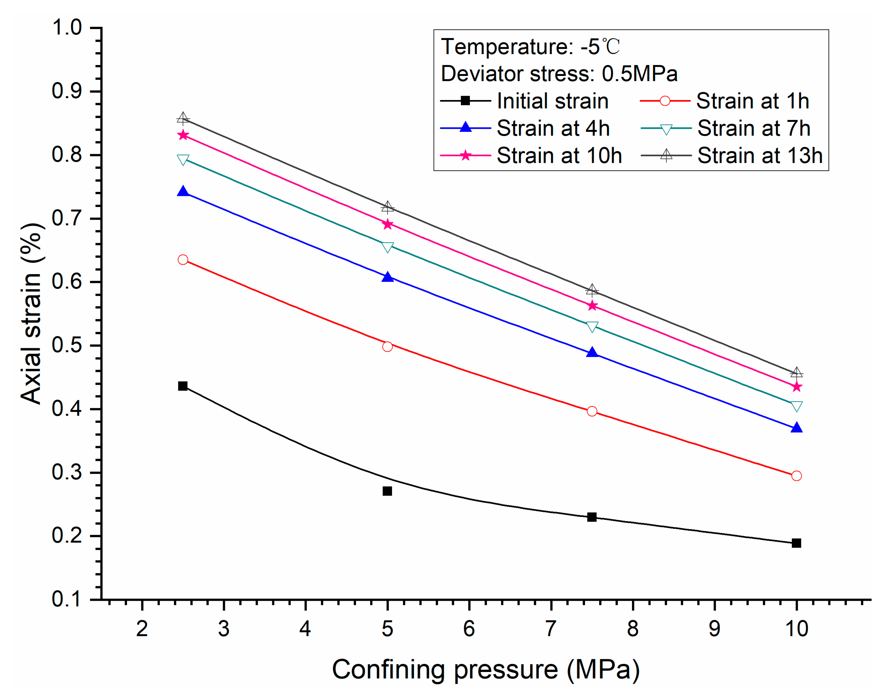
Figure 2c shows the creep curves of methane hydrate-bearing frozen specimens under different confining pressures of 2.5 MPa, 5 MPa, 7.5 MPa, and 10 MPa, with deviator stress of 0.5 MPa, and the temperature of −5 °C. Confining pressure can influence the creep behavior of the specimens greatly. A higher confining pressure made the specimen denser, enhanced the interaction between the grains and hydrate and ice particles, restricting the movement of particles, which increased the ability to resist cementing structure damage for specimens. As a result, less axial strain was observed when the specimen was sheared under higher confining pressure conditions.
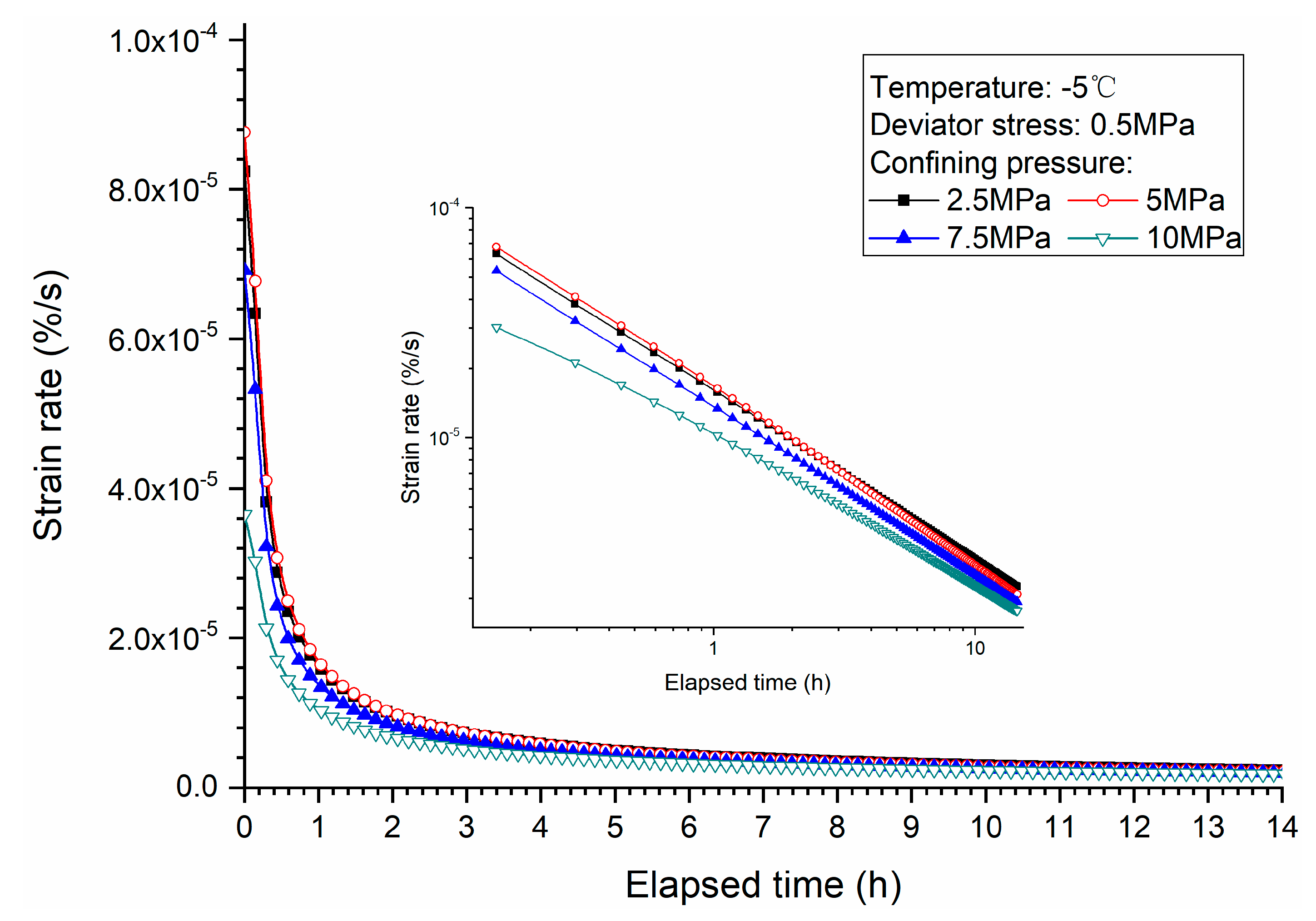
Figure 9 shows the influence of confining pressure on strain rate during the specimen creeping. It shows that the creep strain rate of the specimen becomes smaller with the increase of confining pressure. Moreover, the relationship between strain rate and elapsed time in the logarithmic coordinate system is also shown in Figure 9, where the attenuation of strain rate varies with elapsed time is relatively small with larger confining pressure. With the creeping of the specimen, the strain rate reached an almost constant value, which decreases with the increase of confining pressure. Jones and Chew [30] studied the influence of confining pressure on the creep behavior of ice and got a similar conclusion.
Figure 10 shows the relationship between the creep strain rate and the axial strain for the methane hydrate-bearing frozen specimens under different confining pressures. It can be found that the creep strain rate under high confining pressure was less than that under the low confining pressure condition when the axial strains are the same. The acculturated axial strain increases with the decrease of confining pressure. That means higher confining pressure makes the specimens stiffer, which is consistent with our previous studies of triaxial shear tests on methane hydrate-ice mixture specimens and methane hydrate-bearing clay and sand sediments [8,9,22,31,32,33]. Moreover, the relationship between strain rate and axial strain in the logarithmic coordinate system is also shown in Figure 10, where the slopes of curves approach a constant value eventually, and the strain rate decrease more slowly with axial strain under larger confining pressure. It can be demonstrated clearly in Figure 11, which shows axial strain versus confining pressure at different times. The results show that axial strains decrease linearly with the increase of confining pressure at different times. This means that the stiffness and failure strength of methane hydrate-bearing frozen specimens enhances with the increase of confining pressure. Similar results can be found in the study of hydrate-bearing sand [32].
3.3. Effects of Temperature
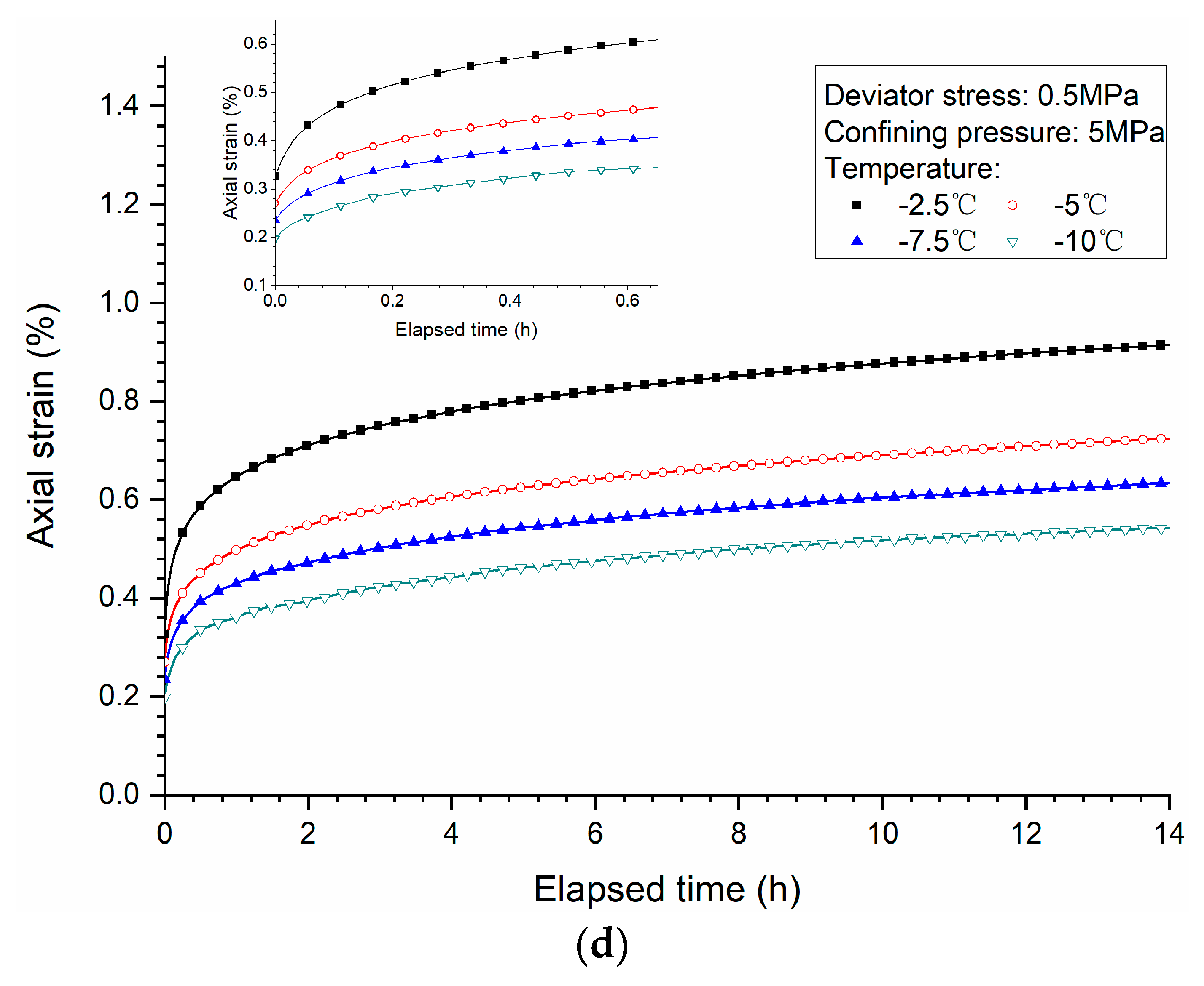
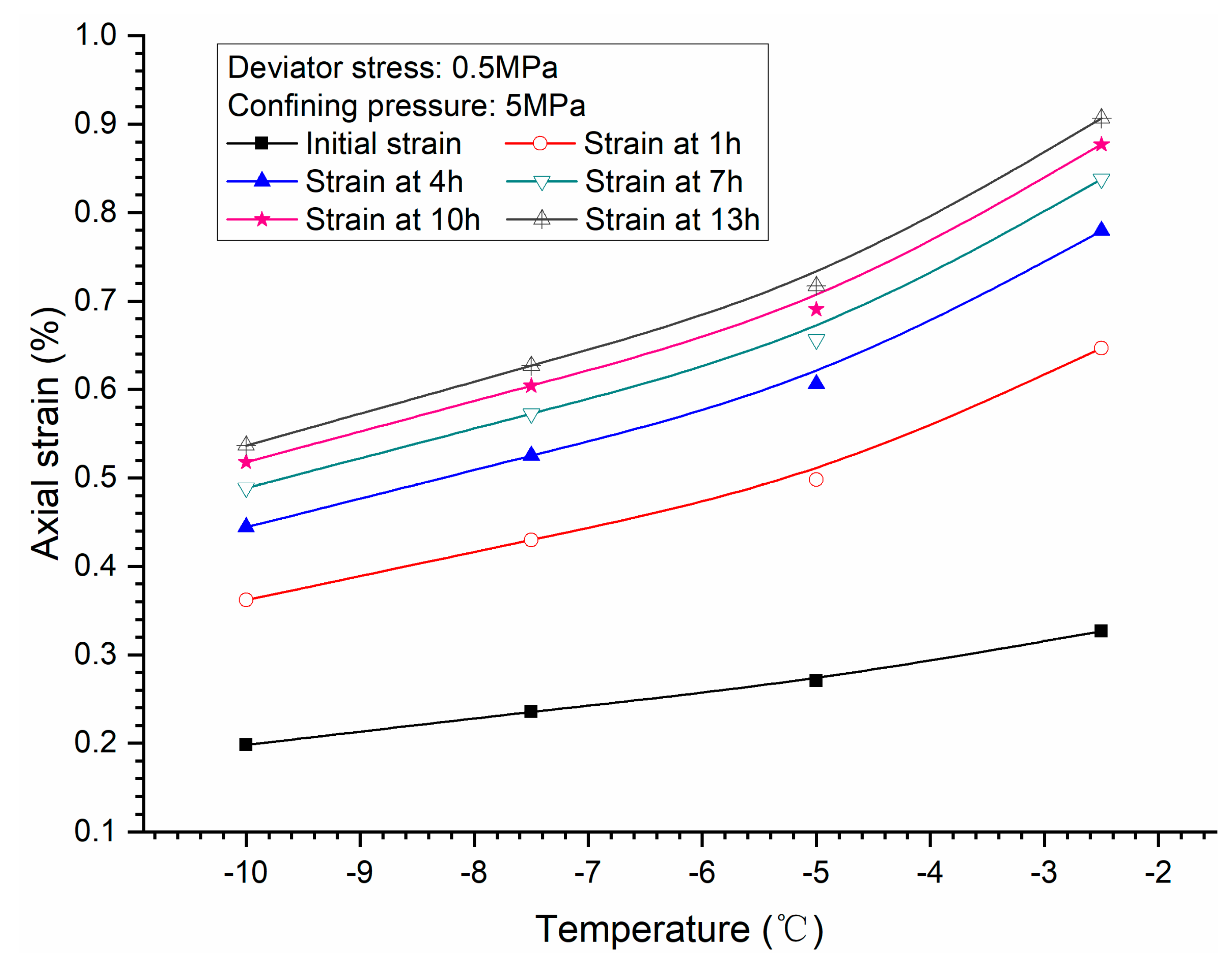
Figure 2d shows the creep curves of methane hydrate-bearing frozen specimens under different temperatures of −2.5 °C, −5 °C, −7.5 °C, and −10 °C, with deviator stress of 0.5 MPa and confining pressure of 5 MPa. Temperature is a significant factor to the creep behavior of the specimens. Under lower temperature during creeping of specimens, it was easier to reach the steady state. The decrease of temperature leads to the decrease of the axial strains at different times of the specimens under constant deviator stress and confining pressure. The ice and methane hydrate becomes much stronger under lower temperature, which would increase the strength of the specimens [34,35,36]. Local dilatancy during creeping induces a local depressurization, leading to methane hydrate dissociation. Higher temperature makes hydrate dissociation easier, further resulting in degradation of the cementing structure of the skeleton and larger deformation of the specimen. At the same time, unfrozen water content has a great influence on the mechanical properties of the specimens. With the decrease of temperature, unfrozen water content will decrease, resulting in the decrease of the lubrication of water between the clay particles, thereby enhancing its deformation resistance [37,38,39].
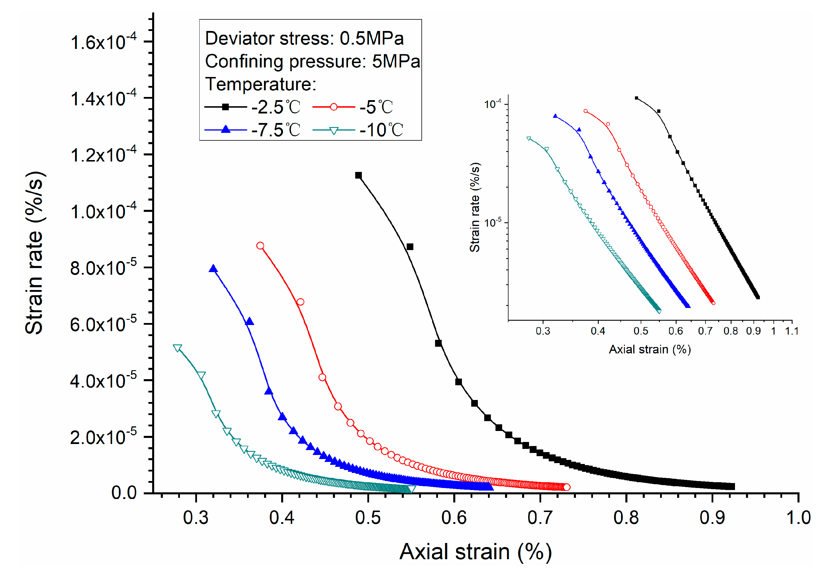
Figure 12 shows the influence of temperature on strain rate during the specimen creeping, where a higher temperature boosts the deformation of the specimen. Moreover, the relationship between strain rate and elapsed time in the logarithmic coordinate system is also shown in Figure 12, where the attenuation of strain rate, which varies with elapsed time, could be slower with lower temperature. The relationship between the creep strain rate and the axial strain for the methane hydrate-bearing frozen specimens under different temperatures are described in Figure 13. It can be found that the creep strain rate under high temperature is larger than that under low temperature at the same axial strains. The accumulated axial strain increases with the temperature, which means lower temperature makes the specimens stiffer. It can be certified in Figure 14, where the increasing axial strains with temperature are plotted. As mentioned earlier in this paper, it was reasonable for the specimens to present such behavior. This result indicates that the temperature drop would enhance the deformation resistance of the methane hydrate-bearing frozen specimens under sub-zero conditions.
3.4. Stress-Strain Relationship
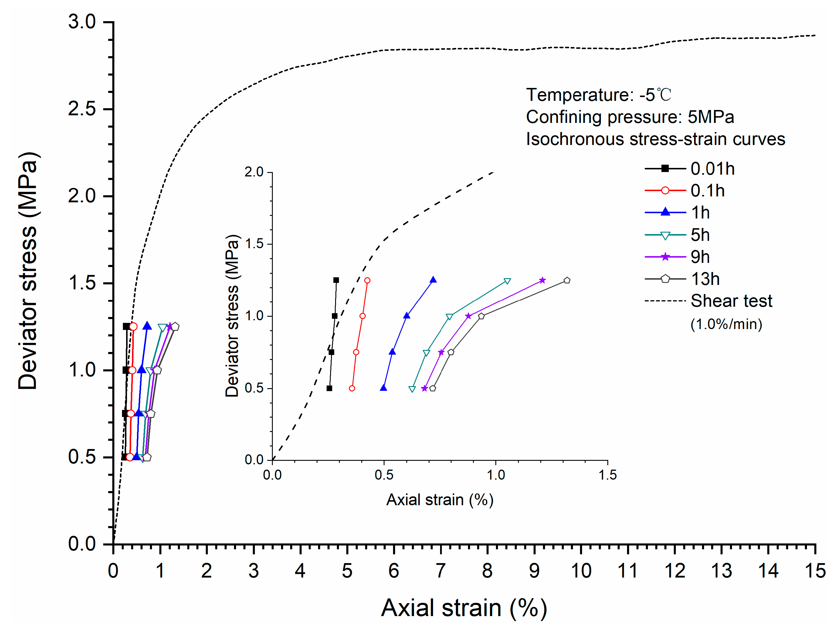
A comparison between the quasi-static stress-strain curve and the isochronous stress-strain curve for the specimens are shown in Figure 15. At the beginning of the creep test, the relationship between deviator stress and axial strain is similar to the quasi-static. However, creep changes the structure of sediments and results in accumulation of deformation under a constant deviator stress. So, at the end of creep test, the stress-strain curve is different from the quasi-static curve. Creep is a kind of visco-plasitic behavior, which results from the internal structure change when the specimen is bearing a constant load.
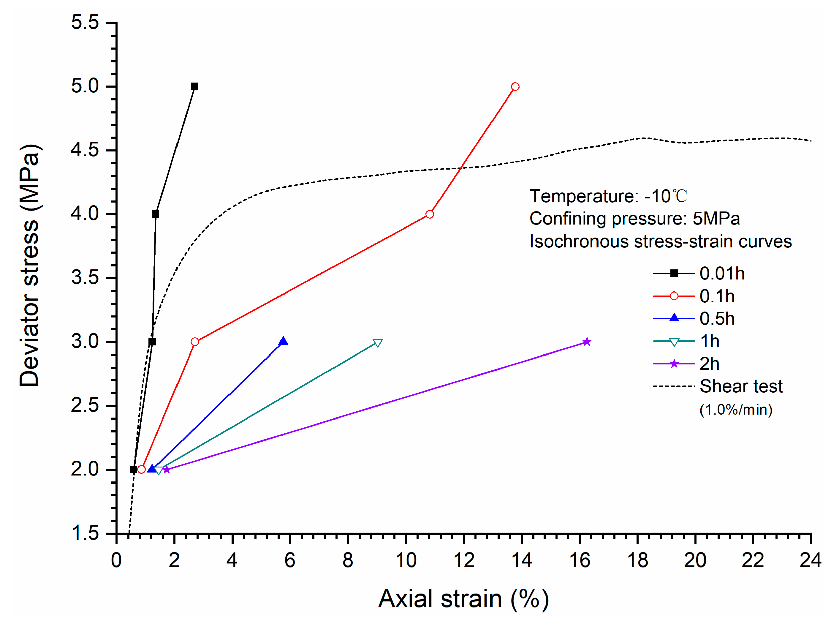
Figure 16 shows that when deviator stress is higher than the strength of the specimen, creep cannot be stable and large deformation occurs. Compared with the low level of deviator stress, the relationship between deviator stress and axial strain is totally different from the quasi-static stress. This is because the higher deviator stress leads to the fatal destruction of the sediment skeleton structure, whereas lower deviator stress just induces local adjustment of the skeleton structure. At the initial stage, the stress–strain relationship between the quasi-static and the isochronous is similar, this is mainly due to the factor of strain rate; the strain rates for the isochronous at the initial stage is similar to the quasi-static, and there is a high degree of coincidence between them, indicating that the strength of specimens has a strong dependence on strain rate or elapsed time.
4. Conclusions
A series of creep tests were conducted to investigate the creep behaviors of synthetic methane hydrate-bearing frozen specimens. Some key influencing factors, including deviator stress, confining pressure, and temperature, were considered. Through the analysis of test data, some conclusions can be drawn as follows:
- Higher deviator stress results in a larger axial strain and strain rate at a specific elapsed time. Under the condition of low deviator stress, the axial strain is not large, and does not get into the tertiary creep stage. However, under the condition of high deviator stress, the axial strain is very large and causes failure.
- Both creep strain and strain rate of methane hydrate-bearing frozen specimens increase with the increase of deviator stress, and the decrease of confining pressure, and temperature.
- Comparison of the stress-strain relationship between creep test and quasi-static triaxial tests shows that when the deviator stress exceeds the quasi-static strength, the specimens will be damaged rather than in stable creep stage during the creeping of the specimens.
All these tests are conducted under constant hydrate saturation. It is known that hydrate dissociation has great impacts on the creep behavior of methane hydrate-bearing frozen specimens. Further studies will be focused on the creep behaviors during hydrate dissociation.
Author Contributions
Conceptualization, Y.L. and J.Z.; Data curation, P.W.; Formal analysis, Y.L. and X.S.; Writing-original draft, P.W. and X.S.; Writing-review and editing, Y.L. and W.L.; Funding acquisition, Y.S.
Funding
This research was funded by the National Natural Science Foundation of China (Grant Nos. 51622603, 51876029 and 51890911), the National Key Research and Development Program of China (Grant Nos. 2017YFC0307305 and 2016YFC0304001), and the Fundamental Research Funds for the Central Universities (Grant No. DUT16RC(4)37).
Conflicts of Interest
The authors declare no conflicts of interest.
References
- Schoderbek, D.; Farrell, H.; Hester, K.; Howard, J.; Raterman, K.; Silpngarmlert, S.; Martin, K.L.; Smith, B.; Klein, P. Oil & Natural Gas Technology, ConocoPhillips Gas Hydrate Production Test: Final Technical Report; National Energy Technology Laboratory: Albany, OR, USA, 2013. [Google Scholar]
- Yamamoto, K.; Dallimore, S. Aurora-JOGMEC-NRCan Mallik 2006–2008 Gas Hydrate Research Project Progress: Fire in the Ice, DOE/NETL Methane Hydrate Newsletter; National Energy Technology Laboratory: Albany, OR, USA, 2008; pp. 1–5. [Google Scholar]
- Yamamoto, K.; Terao, Y.; Fujii, T.; Ikawa, T.; Seki, M.; Matsuzawa, M.; Kanno, T. Operational overview of the first offshore production test of methane hydrates in the Eastern Nankai Trough. In Proceedings of the Offshore Technology Conference, Houston, TX, USA, 5–8 May 2014. [Google Scholar]
- Ning, F.; Yu, Y.; Kjelstrup, S.; Vlugt, T.J.H.; Glavatskiy, K. Mechanical properties of clathrate hydrates: Status and perspectives. Energy Environ. Sci. 2012, 5, 6779–6795. [Google Scholar] [CrossRef]
- Rutqvist, J.; Moridis, G.J.; Grover, T.; Collett, T. Geomechanical response of permafrost-associated hydrate deposits to depressurization-induced gas production. J. Pet. Sci. Eng. 2009, 67, 1–12. [Google Scholar] [CrossRef] [Green Version]
- Sakamoto, Y.; Kakumoto, M.; Miyazaki, K.; Tenma, N.; Komai, T.; Yamaguchi, T.; Shimokawara, M. Numerical study on dissociation of methane hydrate and gas production behavior in laboratory-scale experiments for depressurization: Part 3—Numerical study on estimation of permeability in methane hydrate reservoir. Int. J. Offshore Polar Eng. 2009, 19, 124–134. [Google Scholar]
- Kato, A.; Nakata, Y.; Hyodo, M.; Yoshimoto, N. Macro and micro behaviour of methane hydrate-bearing sand subjected to plane strain compression. Soils Found. 2016, 56, 835–847. [Google Scholar] [CrossRef]
- Hyodo, M.; Li, Y.; Yoneda, J.; Nakata, Y.; Yoshimoto, N.; Nishimura, A. Effects of dissociation on the shear strength and deformation behavior of methane hydrate-bearing sediments. Mar. Pet. Geol. 2014, 51, 52–62. [Google Scholar] [CrossRef]
- Li, Y.; Liu, W.; Zhu, Y.; Chen, Y.; Song, Y.; Li, Q. Mechanical behaviors of permafrost-associated methane hydrate-bearing sediments under different mining methods. Appl. Energy 2016, 162, 1627–1632. [Google Scholar] [CrossRef]
- Uchida, S.; Xie, X.G.; Leung, Y.F. Role of critical state framework in understanding geomechanical behavior of methane hydrate-bearing sediments. J. Geophys. Res. Solid Earth 2016, 121, 5580–5595. [Google Scholar] [CrossRef]
- Liu, L.; Lu, X.; Zhang, X.; Liu, C.; Du, B. Numerical simulations for analyzing deformation characteristics of hydrate-bearing sediments during depressurization. Adv. Geo-Energy Res. 2017, 1, 135–147. [Google Scholar] [CrossRef] [Green Version]
- Gupta, S.; Deusner, C.; Haeckel, M.; Helmig, R.; Wohlmuth, B. Testing a coupled hydro-thermo-chemo-geomechanical model for gas hydrate bearing sediments using triaxial compression lab experiments. Geochem. Geophys. Geosyst. 2017, 18. [Google Scholar] [CrossRef]
- Mountjoy, J.; Pecher, I.; Henrys, S.; Barnes, P.; Plaza-Faverola, A. Creeping deformation mechanisms for mixed hydrate-sediment submarine landslides. In Proceedings of the EGU General Assembly 2013, Vienna, Austria, 7–12 April 2013. [Google Scholar]
- Miyazaki, K.; Yanaguchi, T.; Sakamoto, Y.; Aoki, K. Time-dependent behaviors of methane-hydrate bearing sedimentsin triaxial compression test. Int. J. JSRM 2011, 7, 43–48. [Google Scholar]
- Parameswaran, V.R.; Paradis, M.; Handa, Y.P. Strength of frozen sand containing tetrahydrofuran hydrate. Can. Geotech. J. 1989, 26, 479–483. [Google Scholar] [CrossRef]
- Cameron, I.; Handa, Y.P.; Baker, T.H.W. Compressive strength and creep behavior of hydrateo-consolidated sand. Can. Geotech. J. 1990, 27, 255–258. [Google Scholar] [CrossRef]
- Parameswaran, V.R. Deformation behaviour and strength of frozen sand. Can. Geotech. J. 1980, 17, 74–88. [Google Scholar] [CrossRef] [Green Version]
- Waite, W.F.; Santamarina, J.C.; Cortes, D.D.; Dugan, B.; Espinoza, D.N.; Germaine, J.; Jang, J.; Jung, J.W.; Kneafsey, T.J.; Shin, H. Physical properties of hydrate-bearing sediments. Rev. Geophys. 2009, 47, 1–38. [Google Scholar] [CrossRef]
- Durham, W.B.; Kirby, S.H.; Stern, L.A.; Zhang, W. The strength and rheology of methane clathrate hydrate. J. Geophys. Res. 2003, 108. [Google Scholar] [CrossRef] [Green Version]
- Miyazaki, K.; Yamaguchi, T.; Sakamoto, Y.; Haneda, H.; Ogata, Y.; Aoki, K.; Okubo, S. Creep of sediment containing synthetic methane hydrate. J. MMIJ 2009, 125, 156–164. [Google Scholar] [CrossRef]
- Miyazaki, K.; Endo, Y.; Tenma, N.; Yamaguchi, T. Constitutive equation for triaxial compression creep of artificial methane-hydrate-bearing sand. J. MMIJ 2015, 131, 47–55. [Google Scholar] [CrossRef]
- Li, Y.; Liu, W.; Song, Y.; Yang, M.; Zhao, J. Creep behaviors of methane hydrate coexisting with ice. J. Nat. Gas Sci. Eng. 2016, 33, 347–354. [Google Scholar] [CrossRef]
- Yakushev, V.S.; Chuvilin, E.M. Natural gas and gas hydrate accumulations within permafrost in Russia. Cold Reg. Sci. Technol. 2000, 31, 189–197. [Google Scholar] [CrossRef]
- Dallimore, S.R.; Collett, T.S. Gas hydrates associated with deep permafrost in the Mackenzie delta, N.W.T., Canada: Regional overview. In Proceedings of the Seventh International Permafrost Conference, Yellowknife, NT, Canada, 23–27 June 1998. [Google Scholar]
- Zhu, Y.; Zhang, Y.; Wen, H.; Lu, Z.; Jia, Z.; Li, Y.; Li, Q.; Liu, C.; Wang, P.; Guo, X. Gas hydrates in the Qilian mountain permafrost, Qinghai, northwest China. Acta Geol. Sin. 2009, 83, 1762–1771. [Google Scholar] [CrossRef]
- Wu, Q.; Jiang, G.; Zhang, P. Assessing the permafrost temperature and thickness conditions favorable for the occurrence of gas hydrate in the Qinghai-Tibet Plateau. Energy Convers. Manag. 2010, 51, 783–787. [Google Scholar]
- Miyazaki, K.; Tenma, N.; Yamaguchi, T. Relationship between creep property and loading-rate dependence of strength of artificial methane-hydrate-bearing Toyoura sand under triaxial compression. Energies 2017, 10, 1466. [Google Scholar] [CrossRef]
- Li, D.; Fan, J.; Wang, R. Research on visco-elastic-plastic creep model of artificially frozen soil under high confining pressures. Cold Reg. Sci. Technol. 2011, 65, 219–225. [Google Scholar] [CrossRef]
- Yang, Y.; Lai, Y.; Chang, X. Experimental and theoretical studies on the creep behavior of warm ice-rich frozen sand. Cold Reg. Sci. Technol. 2010, 63, 61–67. [Google Scholar] [CrossRef]
- Jones, S.J.; Chew, H.A.M. Creep of ice as a function of hydrostatic pressure. J. Phys. Chem. 1983, 87, 4064–4066. [Google Scholar] [CrossRef]
- Hyodo, M.; Li, Y.; Yoneda, J.; Nakata, Y.; Yoshimoto, N.; Kajiyama, S.; Nishimura, A.; Song, Y. A comparative analysis of mechanical behavior of carbon dioxide and methane hydrate-bearing sediments. Am. Mineral. 2014, 99, 178–183. [Google Scholar] [CrossRef]
- Hyodo, M.; Li, Y.; Yoneda, J.; Nakata, Y.; Yoshimoto, N.; Nishimura, A.; Song, Y. Mechanical behavior of gas-saturated methane hydrate-bearing sediments. J. Geophys. Res. Solid Earth 2013, 118, 5185–5194. [Google Scholar] [CrossRef] [Green Version]
- Li, Y.; Song, Y.; Yu, F.; Liu, W.; Zhao, J. Experimental study on mechanical properties of gas hydrate-bearing sediments using kaolin clay. China Ocean Eng. 2011, 25, 113–122. [Google Scholar] [CrossRef]
- Helgerud, M.B.; Waite, W.F.; Kirby, S.H.; Nur, A. Elastic wave speeds and moduli in polycrystalline ice Ih, sI methane hydrate, and sII methane-ethane hydrate. J. Geophys. Res. 2009, 114, B2212. [Google Scholar] [CrossRef]
- Hyodo, M.; Hyde, A.F.L.; Nakata, I.; Yoshimoto, N.; Fukunaga, M.; Kubo, K.; Nanjo, Y.; Matsuo, T.; Nakamura, K. Triaxial Compressive Strength of Methane Hydrate. In Proceedings of the Twelfth International Offshore and Polar Engineering Conference, Kitakyushu, Japan, 26–31 May 2002; pp. 422–428. [Google Scholar]
- Song, Y.; Yu, F.; Li, Y.; Liu, W.; Zhao, J. Mechanical property of artificial methane hydrate under triaxial compression. J. Nat. Gas Chem. 2010, 19, 246–250. [Google Scholar] [CrossRef]
- Czurda, K.A.; Hohmann, M. Freezing effect on shear strength of clayey soils. Appl. Clay Sci. 1997, 12, 165–187. [Google Scholar] [CrossRef]
- Chamberlain, E.; Groves, C.; Perham, R. The mechanical behaviour of frozen earth materials under high pressure triaxial test conditions. Géotechnique 1972, 22, 469–483. [Google Scholar] [CrossRef]
- Alkire, B.D.; Andersland, O.B. The Effect of Confining Pressure on the Mechanical Properties of Sand–Ice Materials. J. Glaciol. 1973, 12, 2747–2754. [Google Scholar] [CrossRef]
Figure 1.
Schematic illustration of experimental apparatus.

Figure 2.
The creep curves of methane hydrate-bearing frozen specimens under different (a) low deviator stresses; (b) high deviator stresses; (c) confining pressures; and (d) temperatures.
Figure 2.
The creep curves of methane hydrate-bearing frozen specimens under different (a) low deviator stresses; (b) high deviator stresses; (c) confining pressures; and (d) temperatures.


Figure 3.
Creep strain rate versus elapsed time for methane hydrate-bearing frozen specimens under low deviator stresses.
Figure 3.
Creep strain rate versus elapsed time for methane hydrate-bearing frozen specimens under low deviator stresses.

Figure 4.
Creep strain rate versus axial strain for methane hydrate-bearing frozen specimens under low deviator stresses.
Figure 4.
Creep strain rate versus axial strain for methane hydrate-bearing frozen specimens under low deviator stresses.
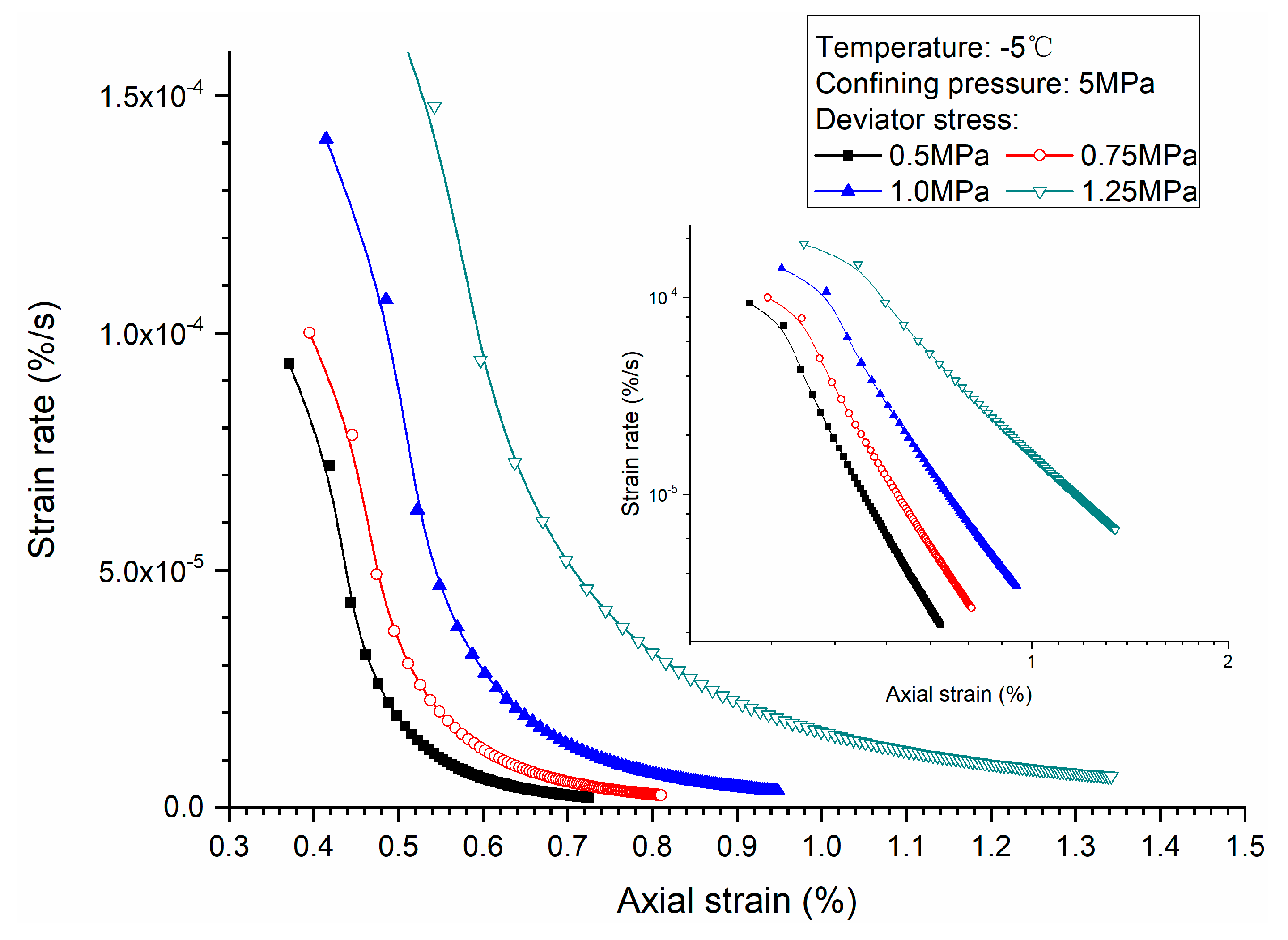
Figure 5.
Initial strain and axial strains versus deviator stress for methane hydrate-bearing frozen specimens under low deviator stresses.
Figure 5.
Initial strain and axial strains versus deviator stress for methane hydrate-bearing frozen specimens under low deviator stresses.

Figure 6.
Creep strain rate versus elapsed time for methane hydrate-bearing frozen specimens under high deviator stresses.
Figure 6.
Creep strain rate versus elapsed time for methane hydrate-bearing frozen specimens under high deviator stresses.

Figure 7.
Creep strain rate versus axial strain for methane hydrate-bearing frozen specimens under high deviator stresses.
Figure 7.
Creep strain rate versus axial strain for methane hydrate-bearing frozen specimens under high deviator stresses.

Figure 8.
Initial strain and axial strains versus deviator stress for methane hydrate-bearing frozen specimens under high deviator stresses.
Figure 8.
Initial strain and axial strains versus deviator stress for methane hydrate-bearing frozen specimens under high deviator stresses.

Figure 9.
Creep strain rate versus elapsed time for methane hydrate-bearing frozen specimens under various confining pressure.
Figure 9.
Creep strain rate versus elapsed time for methane hydrate-bearing frozen specimens under various confining pressure.

Figure 10.
Creep strain rate versus axial strain for methane hydrate-bearing frozen specimens under various confining pressure.
Figure 10.
Creep strain rate versus axial strain for methane hydrate-bearing frozen specimens under various confining pressure.
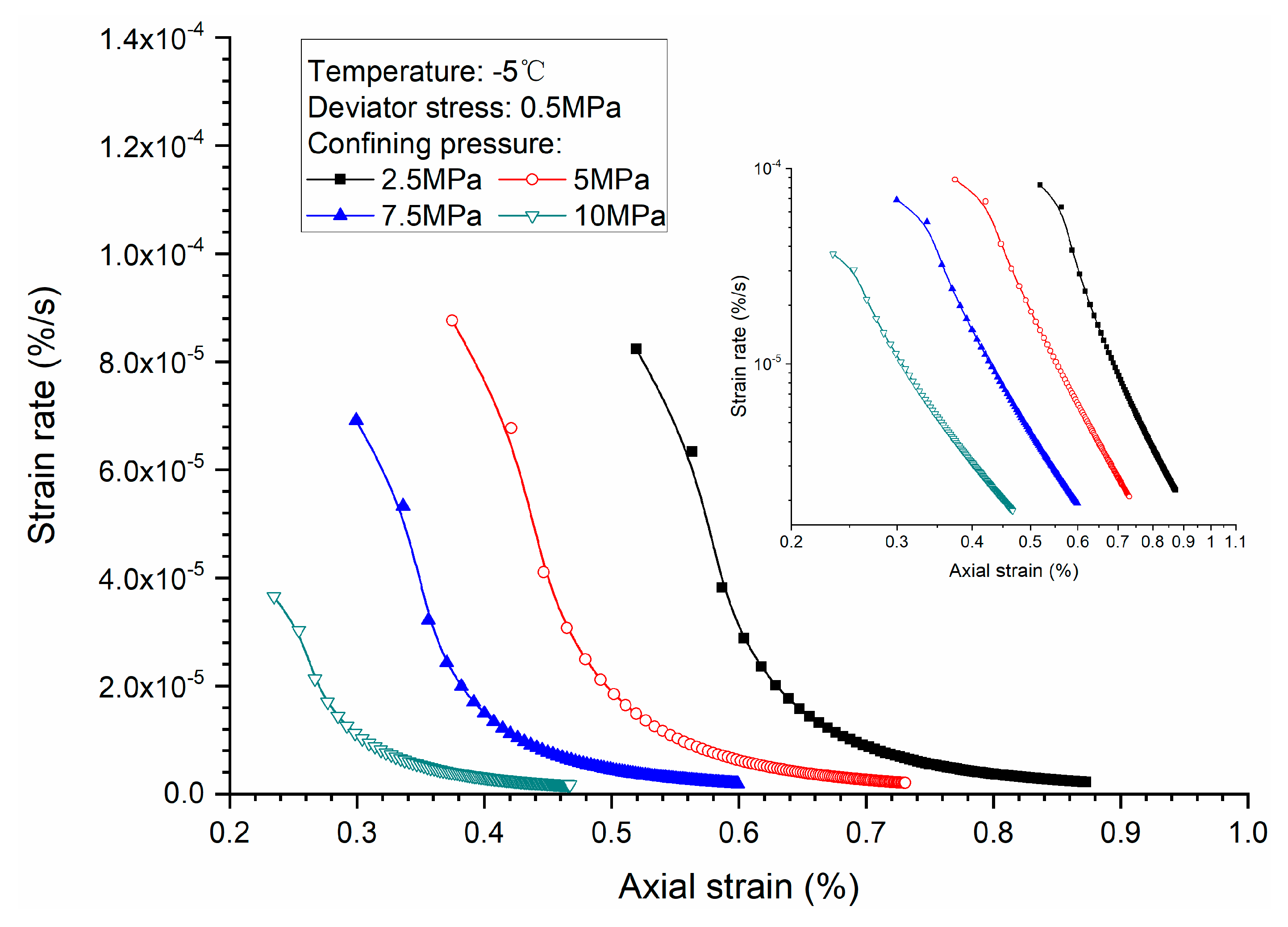
Figure 11.
Initial strain and axial strains versus confining pressure for methane hydrate-bearing frozen specimens.
Figure 11.
Initial strain and axial strains versus confining pressure for methane hydrate-bearing frozen specimens.

Figure 12.
Creep strain rate versus elapsed time for methane hydrate-bearing frozen specimens under various temperatures.
Figure 12.
Creep strain rate versus elapsed time for methane hydrate-bearing frozen specimens under various temperatures.
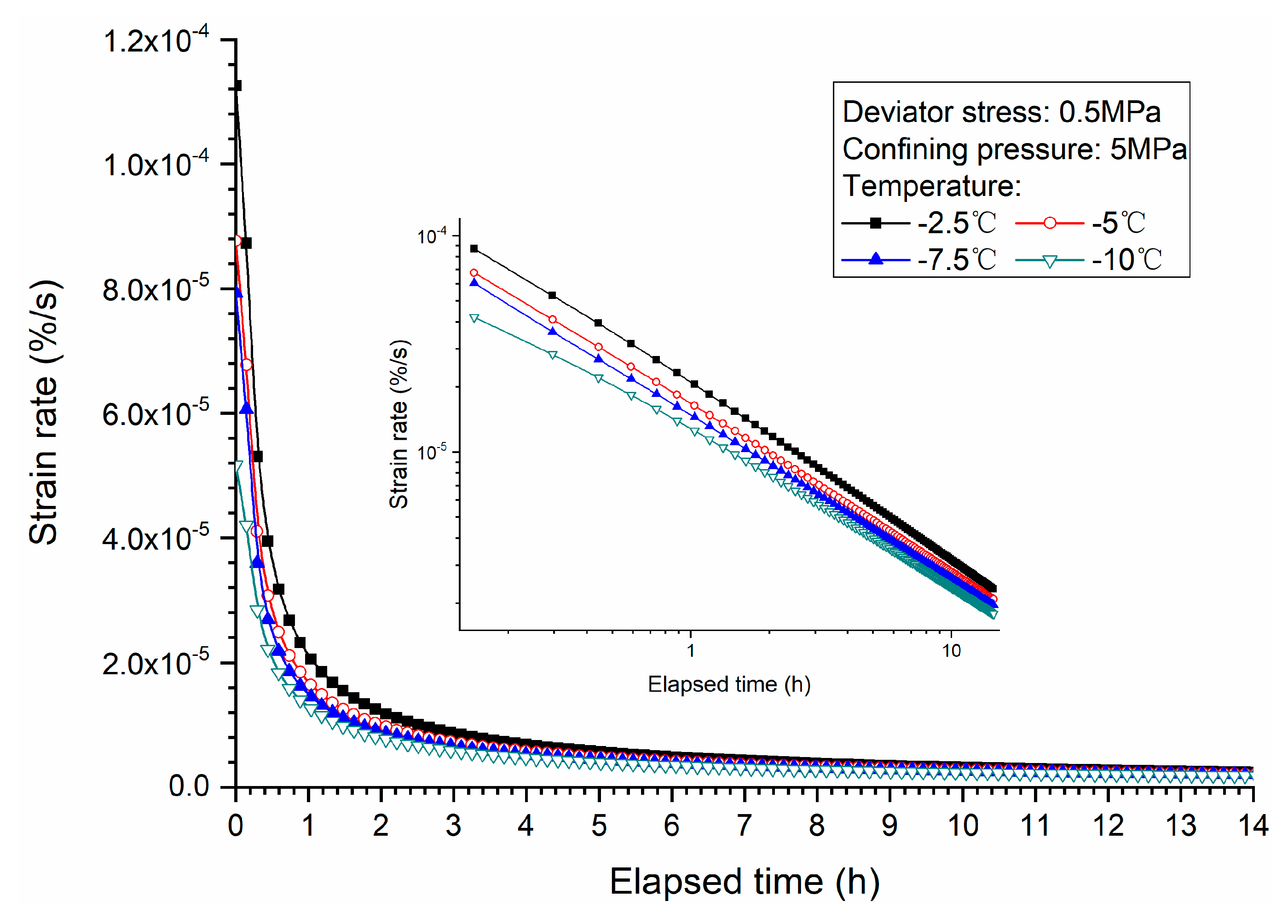
Figure 13.
Creep strain rate versus axial strain for methane hydrate-bearing frozen specimens under various temperatures.
Figure 13.
Creep strain rate versus axial strain for methane hydrate-bearing frozen specimens under various temperatures.

Figure 14.
Initial strain and axial strains versus temperature for methane hydrate-bearing frozen specimens.
Figure 14.
Initial strain and axial strains versus temperature for methane hydrate-bearing frozen specimens.

Figure 15.
The isochronous stress-strain curves for methane hydrate-bearing frozen specimens under low deviator stresses.
Figure 15.
The isochronous stress-strain curves for methane hydrate-bearing frozen specimens under low deviator stresses.

Figure 16.
The isochronous stress-strain curves for methane hydrate-bearing frozen specimens under high deviator stresses.
Figure 16.
The isochronous stress-strain curves for methane hydrate-bearing frozen specimens under high deviator stresses.


Table 1.
Conditions of creep tests.
| Void Ratio | Hydrate Saturation (%) | Temperature (°C) | Deviator Stress (MPa) | Confining Pressure (MPa) |
|---|---|---|---|---|
| 1.5 | 26–33 | −2.5 | 0.5 | 5 |
| −5 | 0.5 | 2.5, 5, 7.5, 10 | ||
| 0.75, 1, 1.25 | 5 | |||
| −7.5 | 0.5 | 5 | ||
| −10 | 0.5, 2, 3, 4, 5 | 5 |
© 2019 by the authors. Licensee MDPI, Basel, Switzerland. This article is an open access article distributed under the terms and conditions of the Creative Commons Attribution (CC BY) license (http://creativecommons.org/licenses/by/4.0/).
Share and Cite
MDPI and ACS Style
Li, Y.; Wu, P.; Sun, X.; Liu, W.; Song, Y.; Zhao, J. Creep Behaviors of Methane Hydrate-Bearing Frozen Sediments. Energies 2019, 12, 251. https://doi.org/10.3390/en12020251
AMA Style
Li Y, Wu P, Sun X, Liu W, Song Y, Zhao J. Creep Behaviors of Methane Hydrate-Bearing Frozen Sediments. Energies. 2019; 12(2):251. https://doi.org/10.3390/en12020251
Chicago/Turabian StyleLi, Yanghui, Peng Wu, Xiang Sun, Weiguo Liu, Yongchen Song, and Jiafei Zhao. 2019. "Creep Behaviors of Methane Hydrate-Bearing Frozen Sediments" Energies 12, no. 2: 251. https://doi.org/10.3390/en12020251
Note that from the first issue of 2016, this journal uses article numbers instead of page numbers. See further details here.