Rotor Speed Observer with Extended Current Estimator for Sensorless Control of Induction Motor Drive Systems


1
State Key Laboratory of Advanced Electromagnetic Engineering and Technology, School of Electrical and Electronic Engineering, Huazhong University of Science and Technology, Wuhan 430074, China
2
Department of Electrical Power and Machines Engineering, Faculty of Engineering, Tanta University, Tanta 31527, Egypt
*
Authors to whom correspondence should be addressed.
Energies 2019, 12(19), 3613; https://doi.org/10.3390/en12193613
Submission received: 9 August 2019
/
Revised: 16 September 2019
/
Accepted: 19 September 2019
/
Published: 21 September 2019
(This article belongs to the Special Issue Electric Vehicle Power Conversion Technologies)
Abstract
:The aim of paper is to investigate an efficient sensorless control method with vector-control technique for the induction motor (IM) drive systems. The proposed technique relies on the indirect rotor-field orientation control scheme (IRFOC). All sensorless control techniques are greatly affected by the observation of the speed estimation procedure. So, an efficacy new algorithm for estimating the rotor speed of the adopted machine is proposed. In addition, a simple effective method to estimate the machine rotor currents is suggested. The adopted rotor-speed observer is based on the concept of IRFOC method and the phase-axis relationships of IM. To ensure the capability of the proposed sensorless speed-control system, a simulation model is developed in the MATLAB/Simulink software environment. The robustness of the new control method is analyzed under parameter uncertainty issue. Furthermore, comprehensive experimental results are obtained. The whole obtained results confirm the validity of the proposed observer for sensorless speed control capability. The given results also verify the effectiveness of the suggested sensorless control system-based IRFOC for speed-control drive systems of IM. Moreover, the results assure that the presented rotor-speed observer is effectively robust via any parameter changes.
1. Introduction
Induction motors are mostly used in industrial application due to their high performance, robustness, efficiency, and cost [1]. Induction Motors (IM) are generally used for high torque and adjustable speed conditions. The performance of IM is strongly dependent on its control. For a high-performance operation for speed control drive systems-based IM, the vector-control technique is preferred [2].
From the view point of the vector control technique, the field orientation scheme can be classified into two main categories dedicated as the direct/feedback (DFOC) and the indirect/feedforward (IRFOC) methods. The main difference between the two methods is in how the orientation angle is acquired. In the DFOC method, the orientation angle is obtained by using sensors (i.e., Hall sensors or flux sensing windings) or direct measurement techniques of terminal voltages and currents [3]. On the other hand, the space-vector flux orientation in the IRFOC method is predicted with the help of the slip and the actual speed. In general, the rotor flux-based IRFOC for induction motor drives is most commonly used in industries for its simplicity [4,5].
Generally, the accuracy level of IRFOC for IM speed-control drive systems is mainly based on the speed-signal measurement process using a speed sensor. However, there are several issues associated with using the sensor of speed, such as difficulties of maintenance, additional cost, reliability issue, and the requirement of an extended shaft for the sensor mounting arrangement [6,7]. The main challenge for researchers in this hot topic is to implement the whole drive system without any sensors for speed measurement. Thus, sensorless speed control strategies of induction motors have been given great attention nowadays [7,8,9,10,11,12,13,14,15,16,17,18,19,20,21,22].
Various methods for the target of sensorless control of induction motors have been outlined which are based on either signal or model algorithms [8,9,10,11,12,13,14,15,16,17,18,19,20,21,22]. However, these methods have been suffering from many defects such as the complexity [17,18,19,20], the integration issue for the flux prediction process at low speeds, or the need of an observer [18,19] or Kalman filter [7]. The influence of high-frequency interference on the machine behavior is the main drawback of the speed estimation algorithm-based signal injection [8,9]. The sensorless control strategy with a model-based estimation algorithm, which is known as model reference adaptive system (MRAS) observer, has reflected the best performance [10,11,12,13,14,15,16] in mid and high-speed operating regions. However, the accuracy of these control methods is inherently decreased under the operation of low-speed narrow to zero because of the integration issue for flux calculations [19]. Furthermore, the model-based sensorless methods have many other defects such as the high dependency on the machine parameters which directly affect the accuracy of the estimation procedure and the large oscillations in transient operation [10,11,12,13,14,15,16].
In order to eliminate these issues, a simple more effective rotor-speed observer for sensorless vector-control capability-based IRFOC of IM drive systems is proposed in this paper. The adopted estimation method for IM rotor speed is implemented with the concept of IRFOC technique and the machine phase-axis relationships without the need for any observer or filter. In addition, a simple estimation method for rotor currents prediction is suggested. The efficacy of the proposed control technology is verified under various conditions of operation with speed and load variations. Furthermore, the robustness of the presented rotor-speed observer is also discussed and confirmed with a parameter uncertainty issue.
The organization of the adopted paper can be reported as follows. In Section 2, the main description of IM dynamic modeling is presented. A simple effective estimation method for the machine rotor currents prediction is completely discussed in Section 3 and verified. Section 4 describes the principle of a sensorless control algorithm based on a new observer for speed estimation. In Section 5, the adopted drive system is simulated in the Matlab/Simulink environment to verify the efficacy of the proposed sensorless control strategy. Section 6 covers the experimental test platform as developed in the laboratory.
2. Dynamic Model of IM
The overall dq model of the adopted induction machine is given as [1]:
The dq-axis voltage components of the stator and rotor windings are expressed as
where, denote the voltage, current, and flux linkage components of the machine sides. In addition, the subscript ‘s’ represents the stator-winding side. Moreover, the subscript ‘r’ defines the rotor-winding side. Furthermore, and denote the stator and rotor winding resistances, respectively.
Considering that,
where, denotes the mechanical angular speed of the arbitrary reference frame. In addition, define the IM mechanical and electrical rotor angular speed, respectively. Furthermore, represents the associated number of poles.
Moreover, the associated flux linkage expressions are obtained as
Considering that,
where, denote the leakage inductances of stator and rotor windings, respectively. In addition, defines the magnetizing inductance.
The electromagnetic torque expression is given as [1].
The equation of the electro-mechanical torque is obtained as
where, denotes the load torque. Furthermore, represent the moment of inertia and the friction coefficient, respectively.
3. A Simple Effective Estimation Method for Rotor Current Prediction
In this section, a simple effective estimation method to predict the machine rotor current is proposed and verified. Aided with the measured three-phase stator voltages and currents and using the abc/dq-axis transformation matrix of IM windings, is based on the command frame angle (slip angle which will be discussed and obtained in the next section) and as the frame angle, The transformation matrix of the IM abc-axis variables into any dq-axis arbitrary reference frame, can be written as follows [1]:
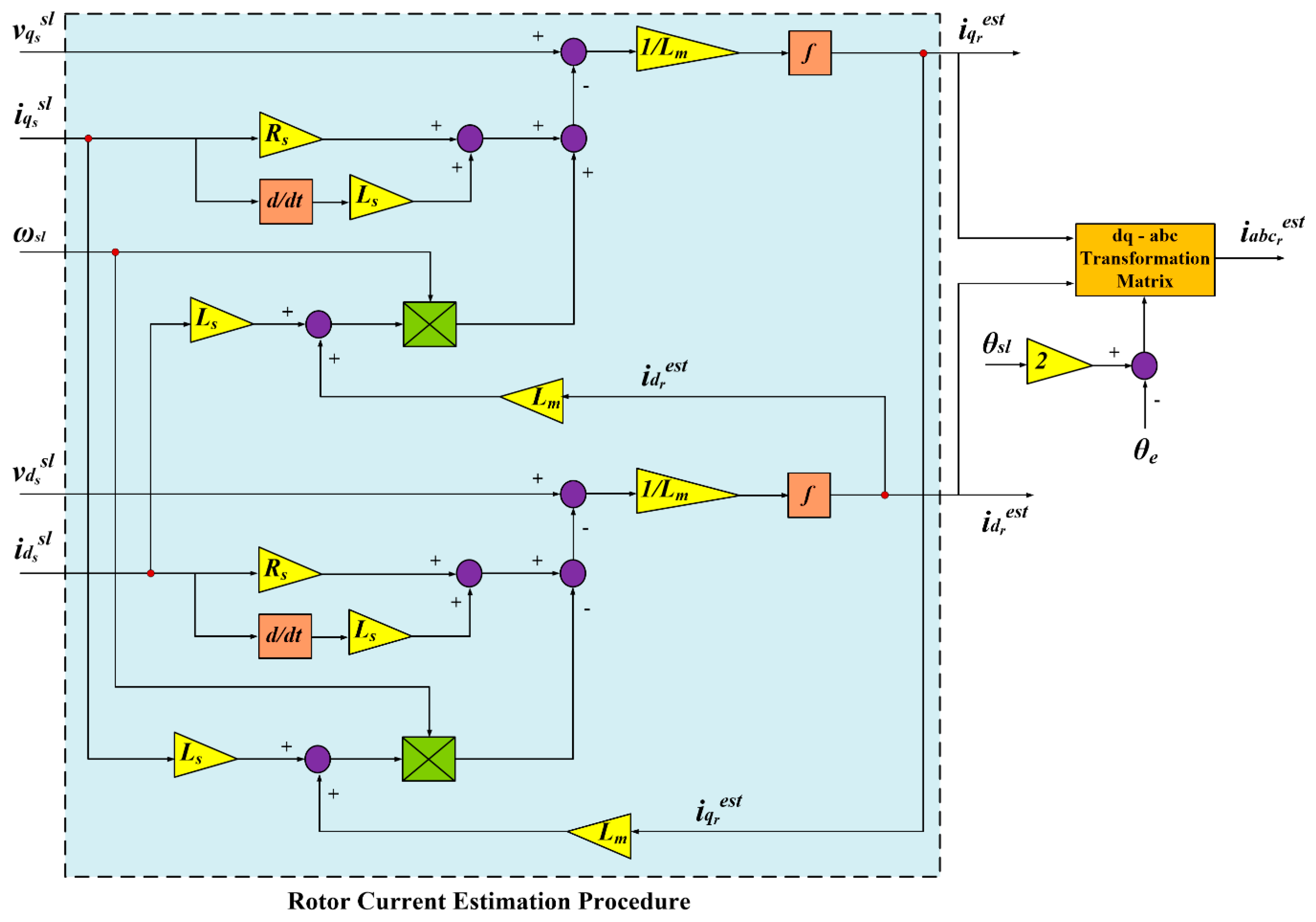
Based on the resulted dq-axis stator voltages and currents, defined with the superscript ‘sl’ in Figure 1, and aided with (1) and (3) considering that the slip speed, is selected as the frame speed, the estimated dq-axis rotor currents can be determined. From which, the corresponding estimated three-phase rotor currents, defined with the superscript ‘est’, can be easily obtained as shown in Figure 1.
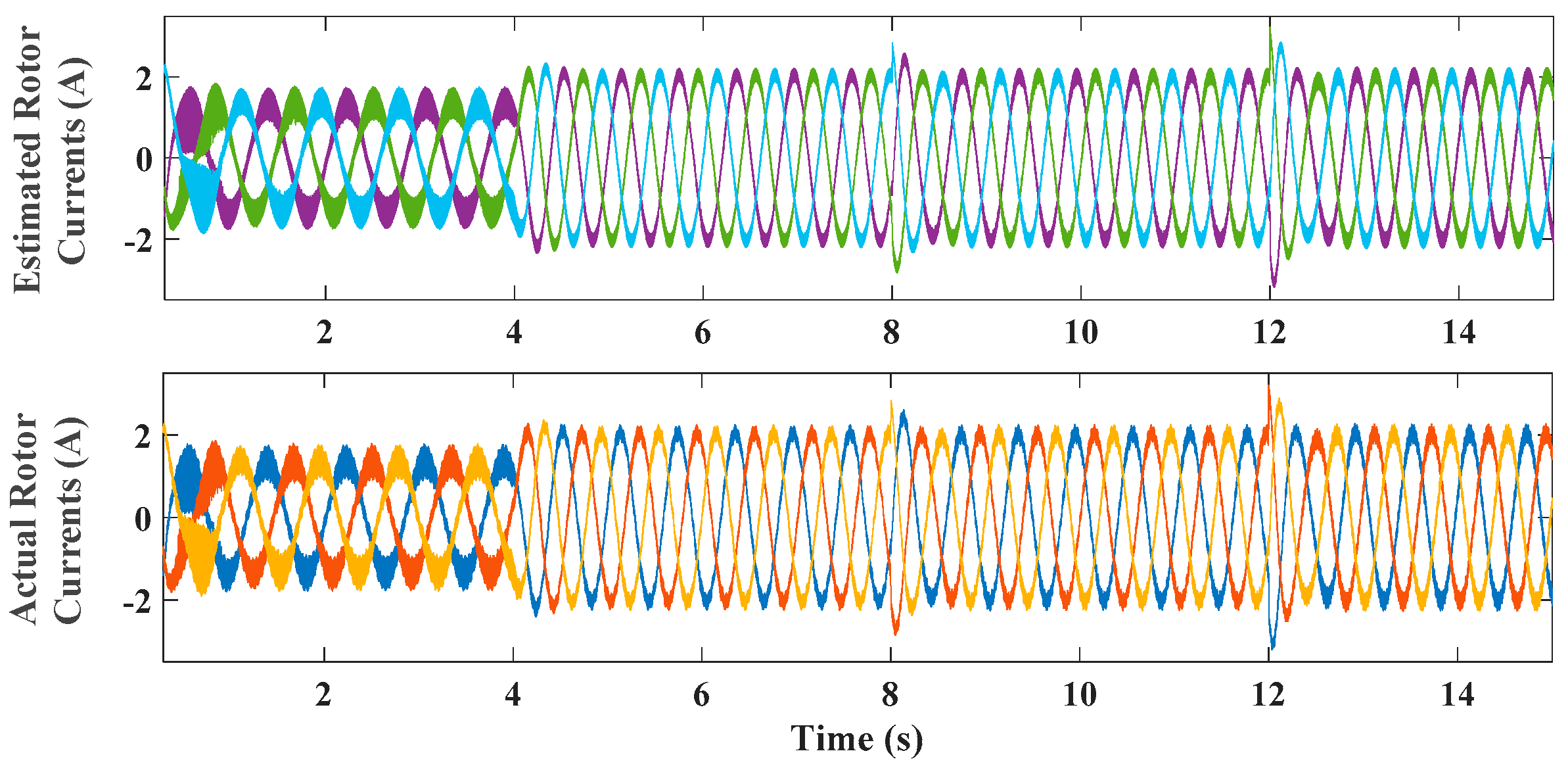
To confirm the efficacy of the proposed estimation procedure for the adopted IM rotor currents, some results are obtained and shown in Figure 2 for the three-phase rotor currents response. It is obvious from Figure 2 that the predicted three-phase rotor currents successfully track the corresponding actual values which confirm the capability of the proposed estimation method, as shown in Figure 1, to effectively predict the machine rotor currents.
4. Proposed Sensorless Control Scheme based a New Rotor-Speed Observer with the Principle of Indirect Field-Orientation Technique
The main concept of filed orientation technique for IM drives is to independently control the flux and torque components [2]. The controllable vector quantities are transformed into its corresponding dq-axis components in synchronous frame (with a position defined as the electrical angle of the stator-winding flux vector) where these quantities appear as dc components [4].
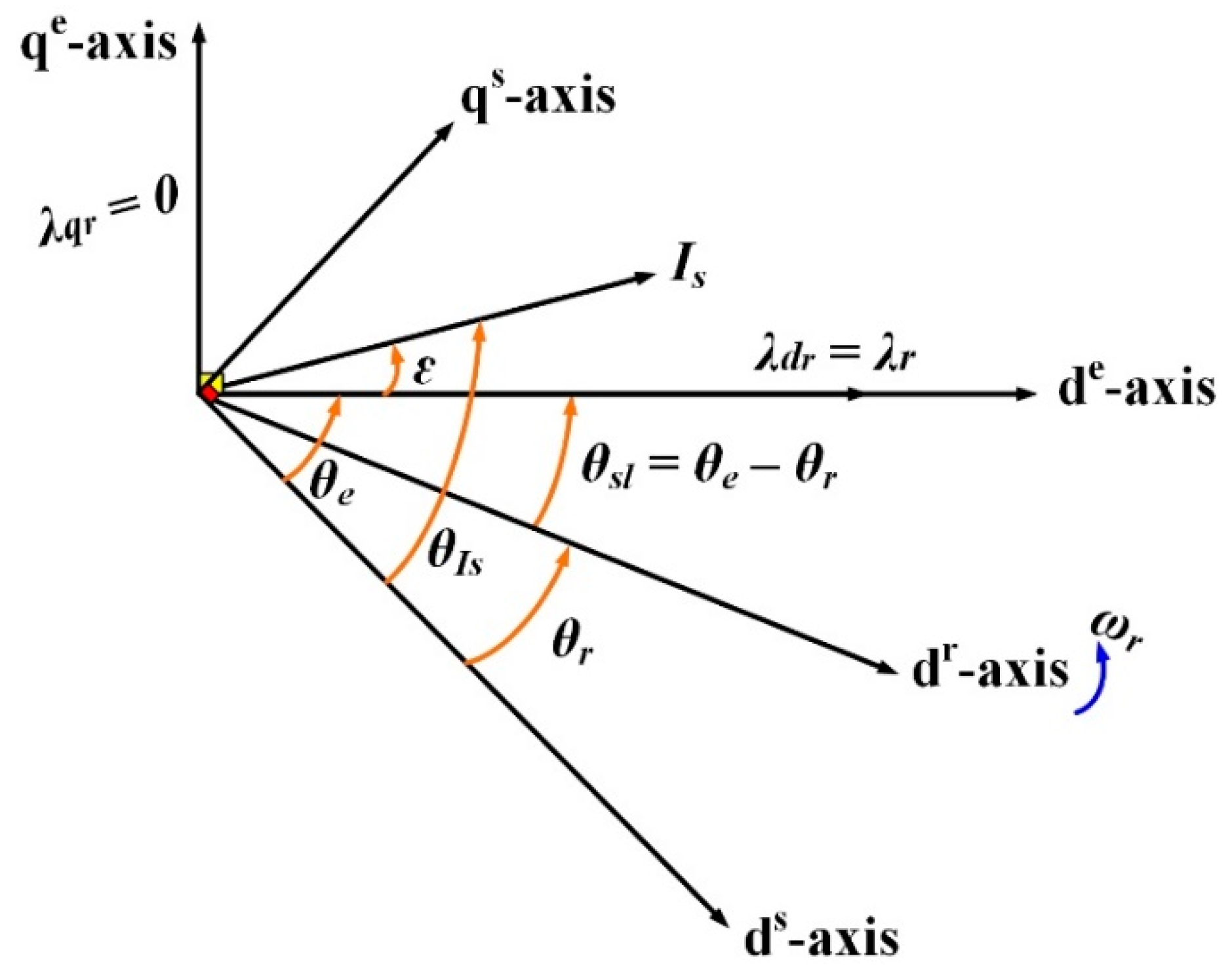
In general, the presented IRFOC method can be realized by aligning the total flux vector of the rotor windings, , with its associated d-axis (de-axis) [2]. In other words, the de-axis flux of the rotor-winding, is equal to the total value of the flux vector (), and hence, the qe-axis flux component, is set to zero (). Figure 3 illustrates the conceptual phase-axis relations of IM.
To detect the flux vector of the rotor windings (the magnitude, and the angle, , the IRFOC method is used in this paper for its popularity in speed control drive systems. Figure 3 describes the main concept of IRFOC using the phase-axis relations of IM. The stator axes are denoted as ds-qs, however, the rotor axes are represented as dr-qr with a speed of as illustrated in Figure 3 [2]. The synchronous frame axes de-qe are movable ahead of the rotor axes by the slip speed, and the angle, In order to investigate the flux and torque control purpose with a decoupled effect, the machine actual torque is controlled via the qe-axis stator current component, and the de-axis current component, is directed to control the corresponding machine as in Figure 3.
Based on the proposed IRFOC method, it is desirable that and From which and using (3) and (5) for a command electromagnetic torque, the command dq-axis stator current components can be obtained, assuming a command constant rotor-flux, and an actual rotor flux, as follows
In addition, the command speed of the machine synchronous reference frame, (electrical angular frequency of stator winding) can be obtained using the measured rotor speed, as.
Hence, the command frame angle, can be obtained by the integration of the frame speed,
The slip-speed, is determined, based on the proposed IRFOC method, as [2]:
In addition, the stator dq-axis current components, and can be determined aided with the measured three-phase stator currents and using the abc/dq-axis transformation matrix of IM windings, based on the command frame angle, as the frame angle, The transformation matrix of the IM abc-axis variables into any corresponding dq components, [1].
Furthermore, the actual flux of the rotor windings, can also be obtained, based on IRFOC, as:
It can be observed from the above analysis that the presented vector-control system mainly relies on the measured speed of the adopted IM, Therefore, a speed encoder is needed for this drive system. In general, the speed sensor will add some issues for the adopted drive system such as increasing the overall cost, suffering from reliability issue, and the need of mechanical arrangements [7].
In order to eliminate these defects, the prediction of the speed signal is the main challenge for the control target. In this paper, a proposed rotor-speed estimation approach is implemented for sensorless control capability of IM drives.
The rotor position of IM, is obtained, aided by the measured voltages and currents as follows:
Firstly, the vector angle of the stator current (with respect to the machine natural axes ds-qs), shown in Figure 3, is obtained using the measured values of the three-phase stator currents as.
where,
In addition, the slip angle, can be determined by integrating the slip-speed obtained from (10). From which, the rotor dq-axis current components, and in the synchronous reference frame, can be obtained based on the angle, and using the abc/dq-axis transformation matrix of IM variables, [1].
Then, based on (3) and using the actual rotor-flux obtained from (11), the de-axis component of the stator current, is determined. In addition, based on the proposed IRFOC ( and using (3), the qe-axis component of the stator current, is also realized.
From which, the vector angle of the stator current (with respect to the axes de-qe), shown in Figure 3, can be determined as:
Finally, the command frame angle, can be estimated as.
From which, the rotor-position of the IM can be obtained based on (9) as.
After getting the estimated angle, the rotor speed can be easily estimated by differentiating the rotor-position of IM (. However, this method gives a fully noisy rotor-speed signal to be estimated which will affect the behavior of the presented IRFOC drive system and will need an observer to overcome this issue [23,24]. Therefore, a very simple approach is suggested in this paper to obtain the estimated rotor-speed signal of IM from the determined rotor-position without the need for any observer.
The proposed method is simply based on supposing a unit polar signal with an absolute value of ‘One’ and an angle of ‘ ’. Then, this polar signal is converted to its cartesian form ‘X and Y’ as follows.
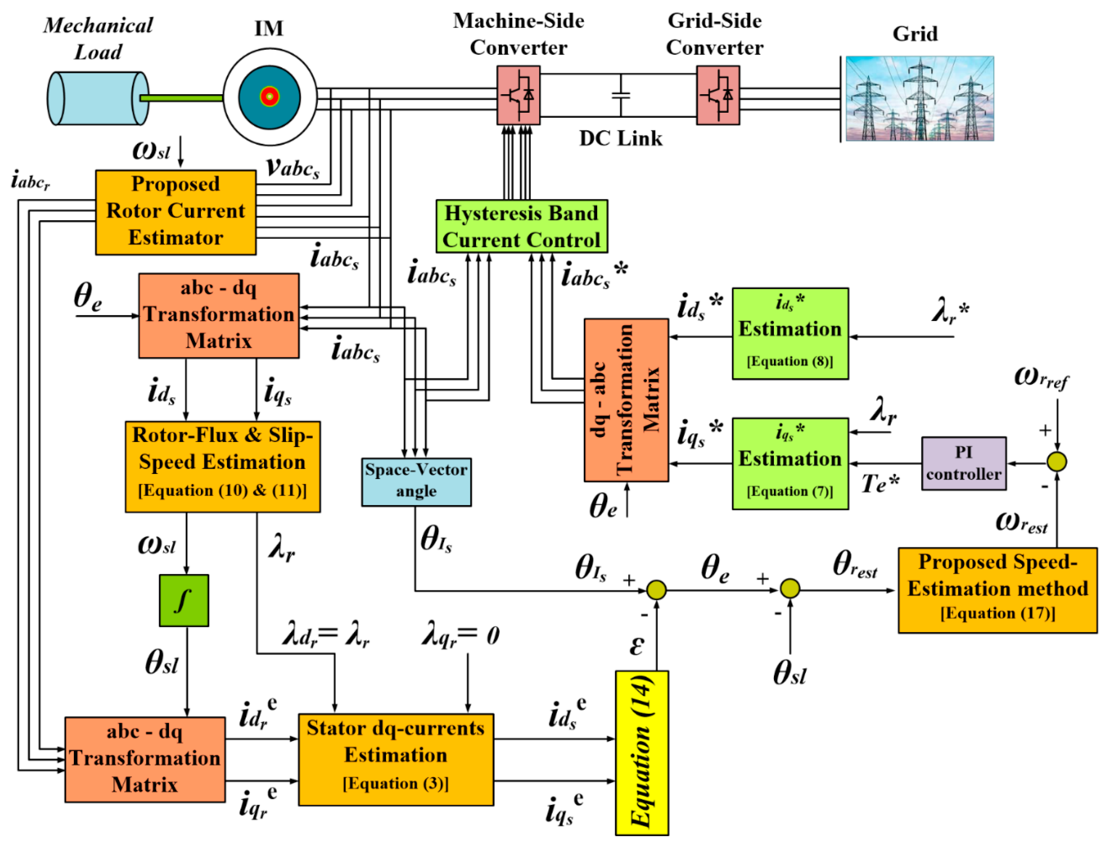
The formula in (17) is simply given based on the mathematical assumption of the differentiation process of ‘ ’. Aided with the estimated rotor-position, from (16), and using two derivative blocks for ‘X and Y’ to obtain the corresponding quantities ‘dX/dt and dY/dt’, then the rotor speed can be smoothly detected using (17). After getting the estimated rotor-speed, a desired speed is set and compared with the predicted value to obtain the corresponding reference torque, as illustrated in Figure 4. Then, the command stator qe-axis current, can be determined using (7) by setting a reference rotor-flux value, Moreover, the command stator de-axis current, can also be obtained using (8).
Finally, the reference three-phase stator currents are obtained using the command currents and with the help of the command frame angle, obtained from (15) and using the inverse of Hence, the difference error between the command three-phase stator currents and the corresponding actual quantities are controlled with the aid of hysteresis-band current controller, as shown in Figure 4, to obtain the associated required pulses of the adopted converter.
5. Simulation Results
In order to validate the suggested speed estimation approach for sensorless control systems of IM, some of the obtained results are presented. The results are given with a four-pole, 1.8 kW IM. All related parameters of the adopted drive system are illustrated in the Appendix A section [25].
5.1. Effectiveness of the Proposed Rotor Speed Observer
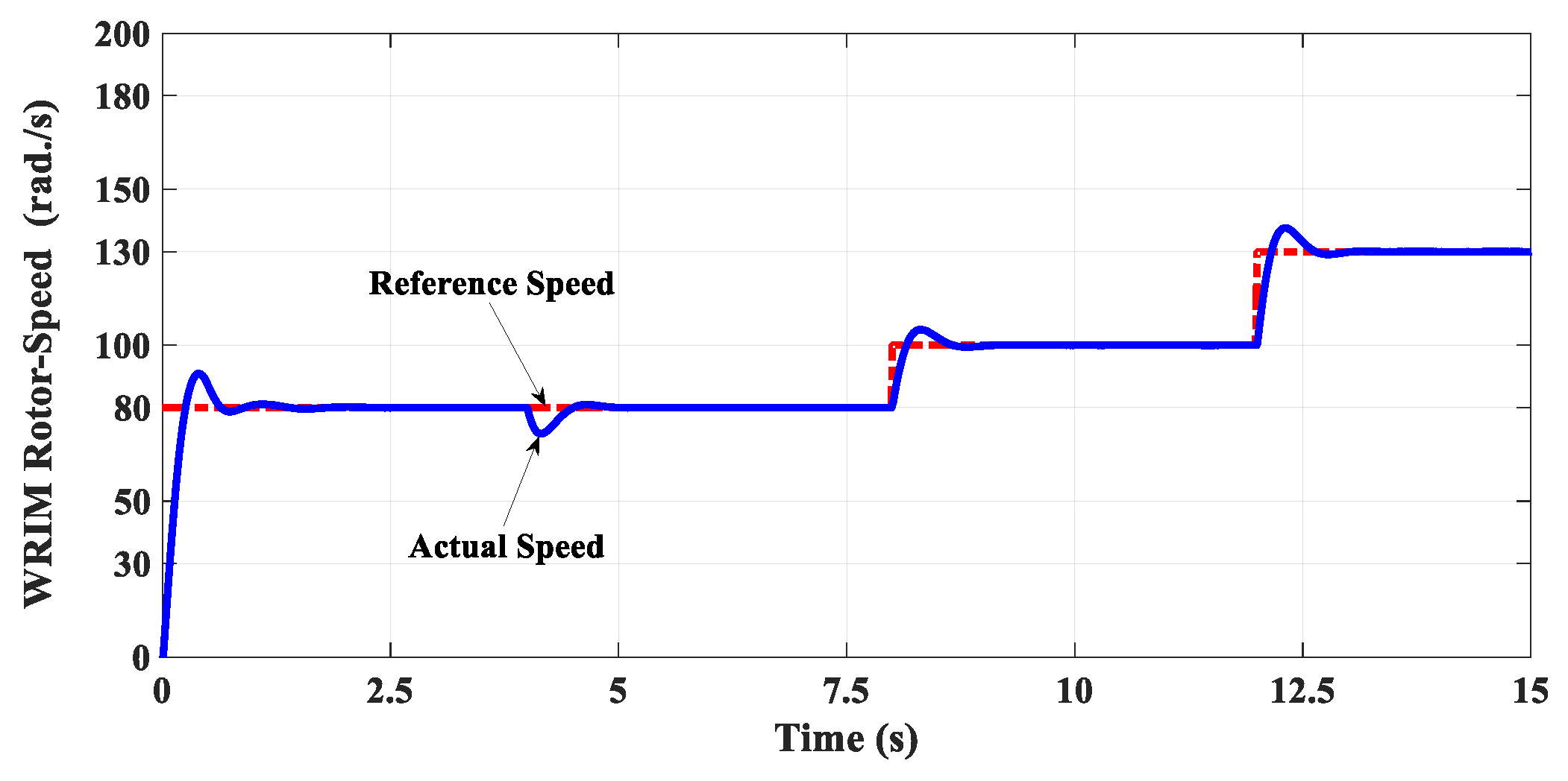
The efficacy of the proposed sensorless control strategy has been studied for a command rotor flux of 0.8 V·s/rad and a reference speed profile shown in Figure 5.
It can be illustrated from Figure 5 that the actual IM rotor-speed tracks its corresponding command value along with the overall reference speed profile. This ensures the effectiveness of the presented IRFOC method for the speed control target of IM drive systems.
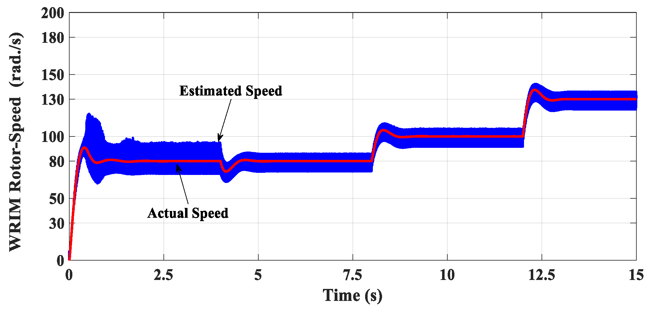
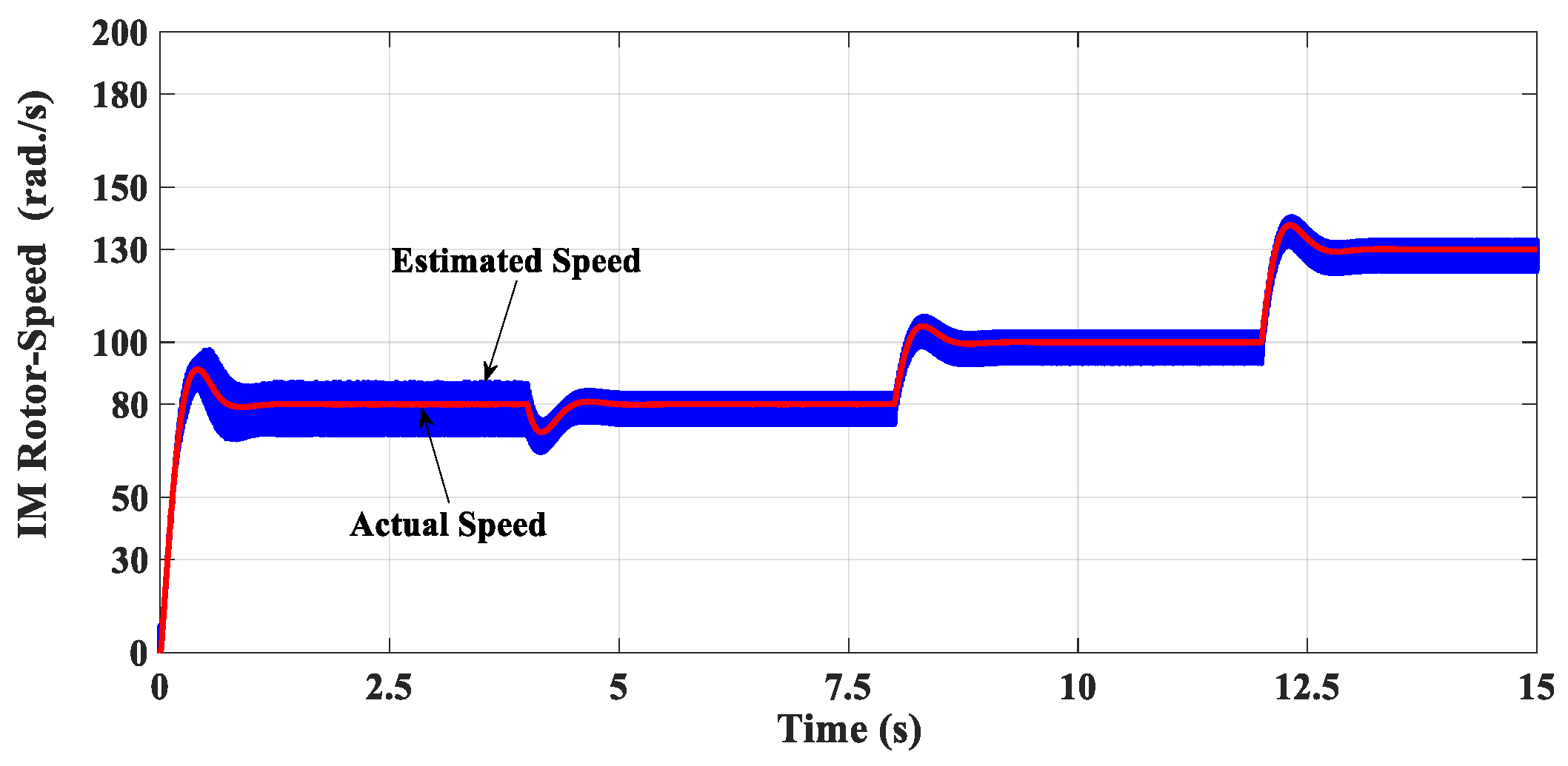
Figure 6 shows the estimated rotor-speed response and the corresponding actual speed response of the adopted IM. It should be noted that the actual IM rotor-speed is measured only for monitoring purposes and not for control. Therefore, it is not illustrated in Figure 4.
It is obvious from Figure 6 that the estimated speed of IM is successfully tracking the actual value which ensures the efficacy of the suggested speed-estimation approach.
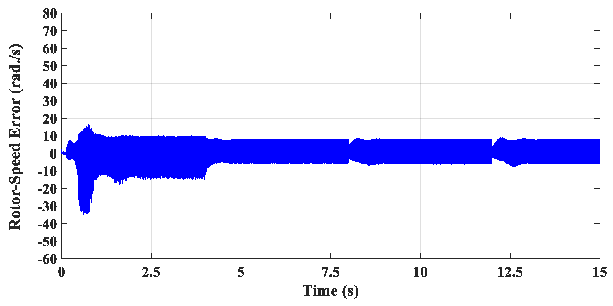
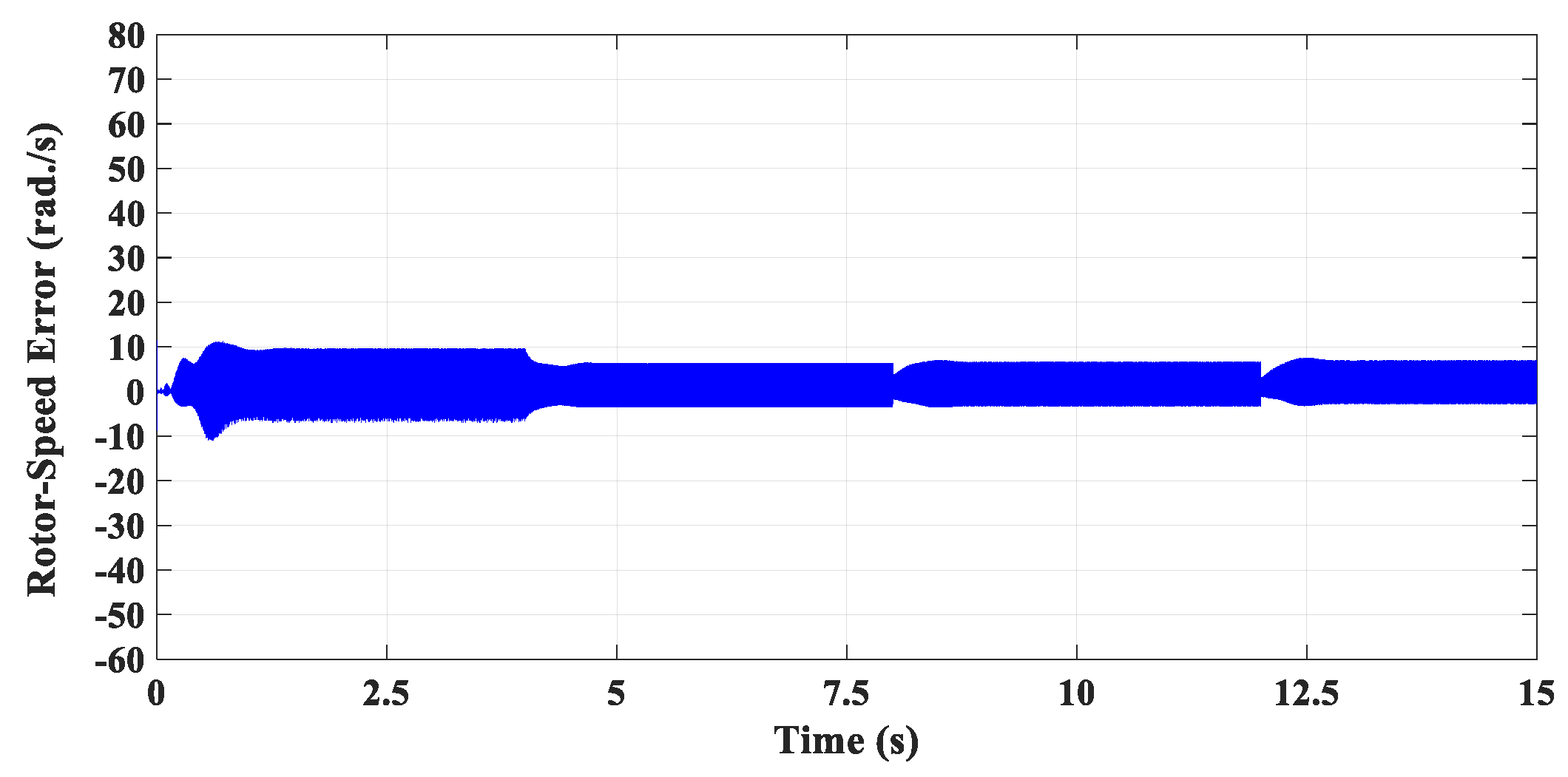
Figure 7 shows the response of the estimation error which is given by
It is obvious from Figure 7 that the speed-estimation error as a percentage of the actual IM rotor-speed has been changed within acceptable percentages which ensures the correlation between the estimated rotor-speed and its corresponding actual value. This confirms the effectiveness of the proposed speed-estimation approach for sensorless vector-control strategy of the IM drive system.
It can also be illustrated from Figure 6 that both the actual speed and the estimated speed response have been changed to track the command speed profile shown in Figure 5. This ensures the capability of the proposed sensorless vector-control strategy for speed-control drive systems of IM.
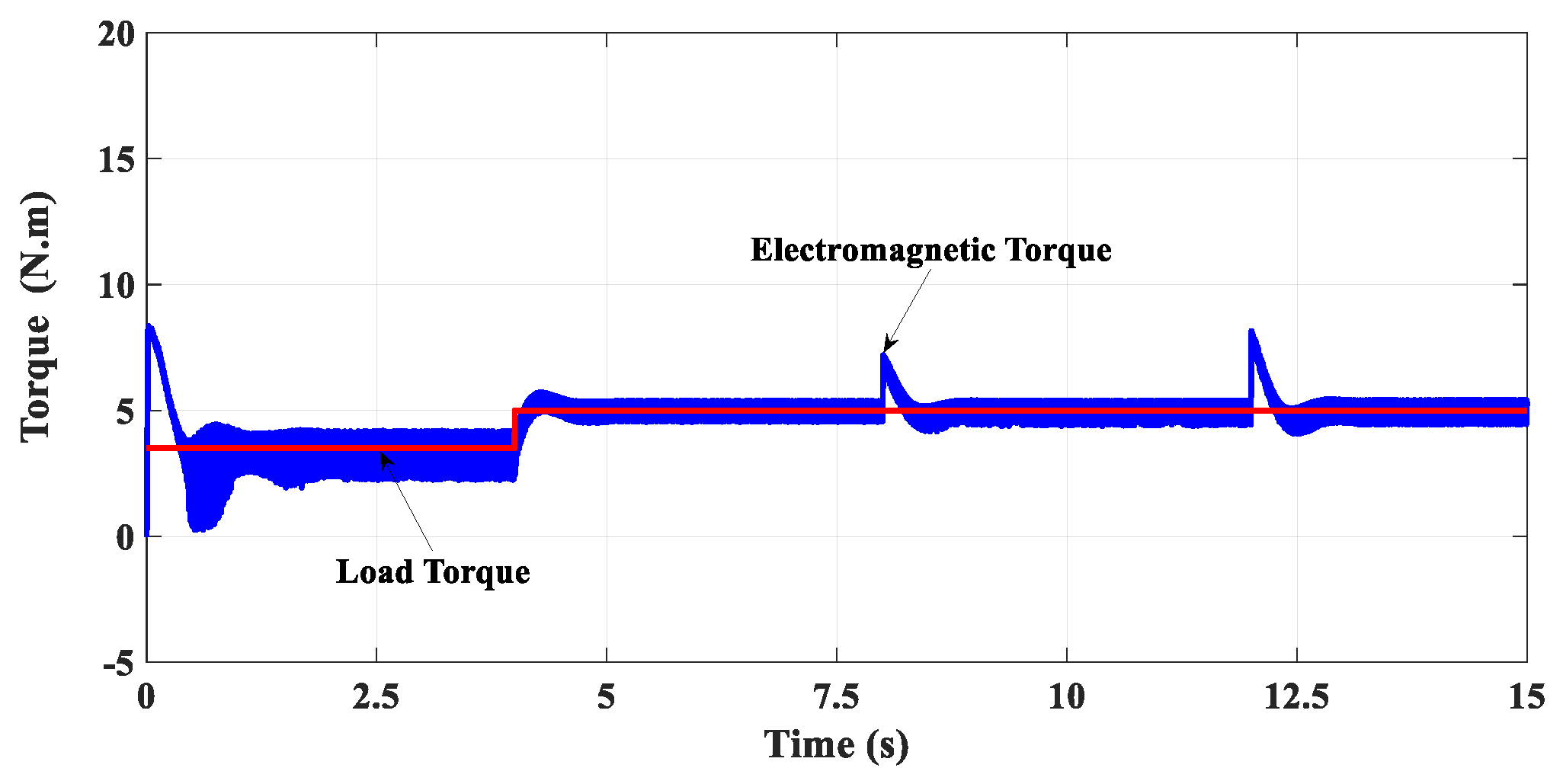
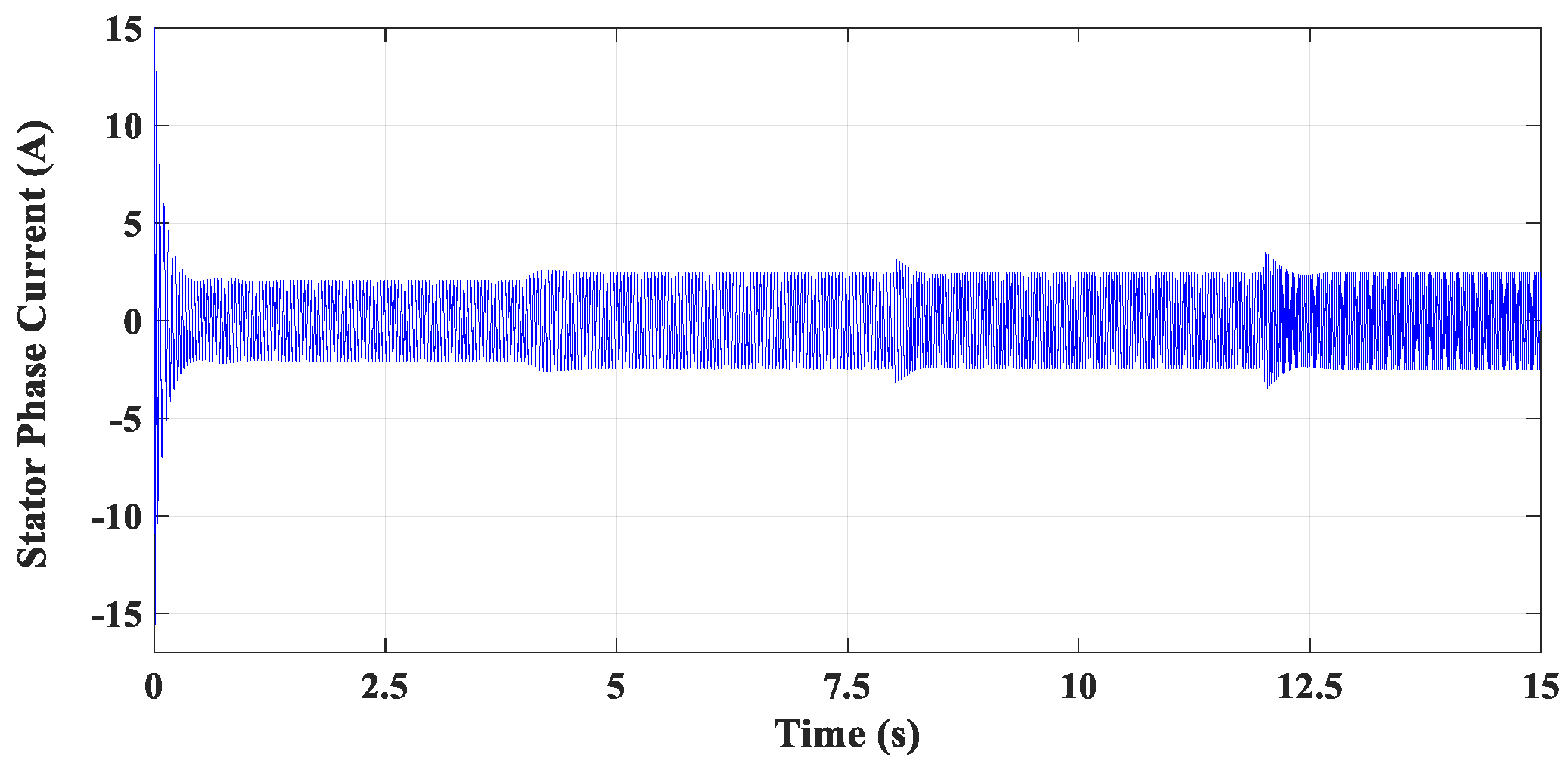
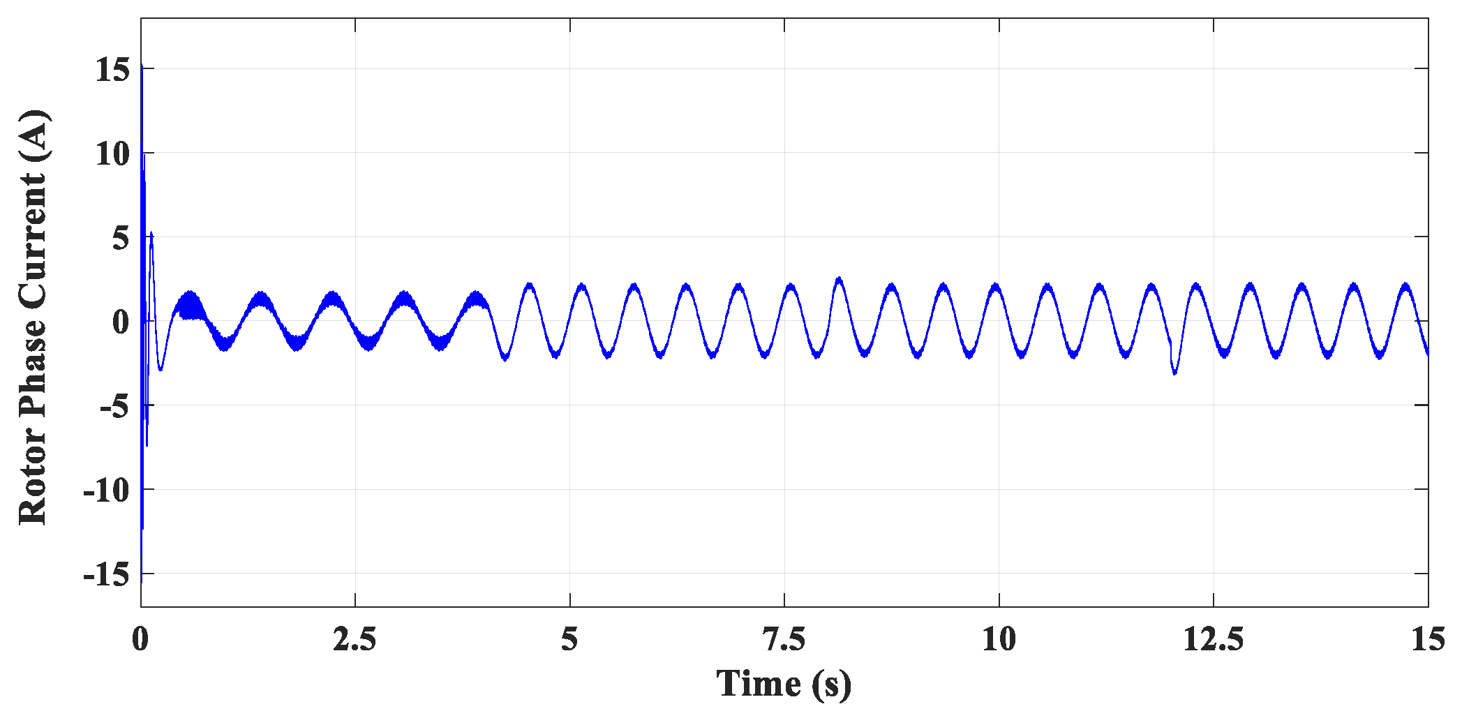
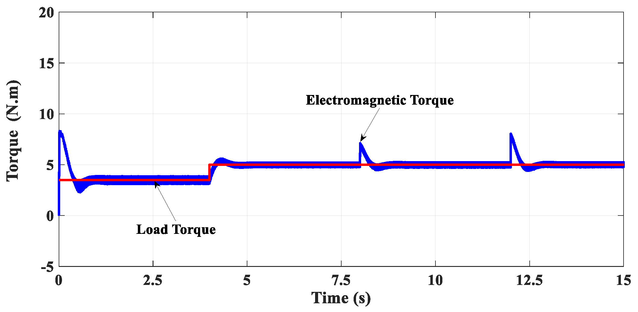
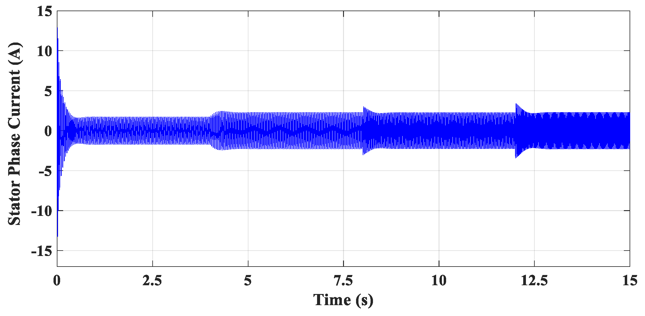
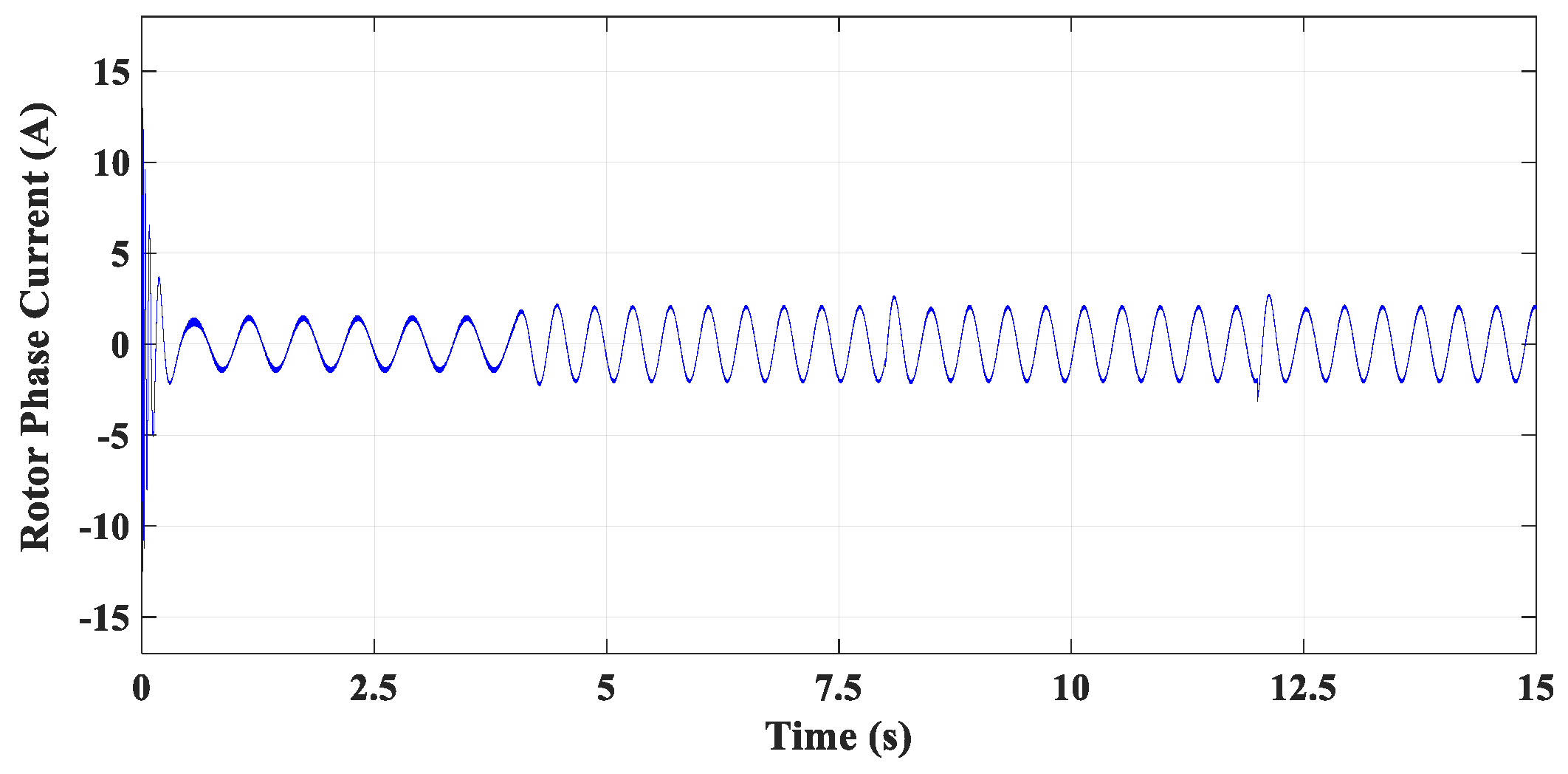
In addition, the response of the load torque variations and the corresponding electromagnetic torque is shown in Figure 8. Furthermore, the responses of the stator phase-current and also the rotor phase-current during different periods are shown in Figure 9 and Figure 10, respectively.
It is obvious that the electromagnetic torque has successfully tracked the load torque variations with a good transient response and a smooth change in both the stator phase current and the rotor phase current as illustrated in Figure 9 and Figure 10, respectively. This validates the efficacy of the proposed sensorless control system for the adopted IM drive applications.
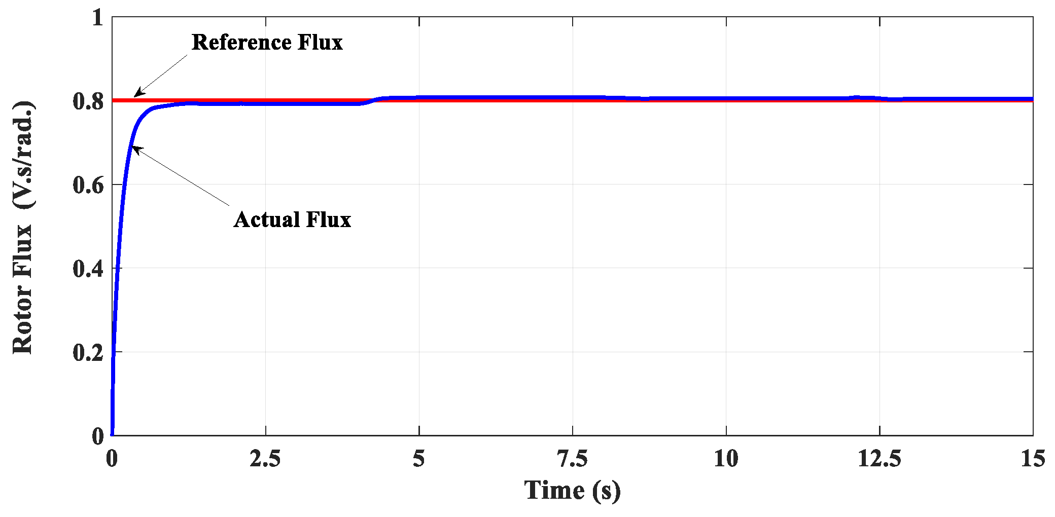
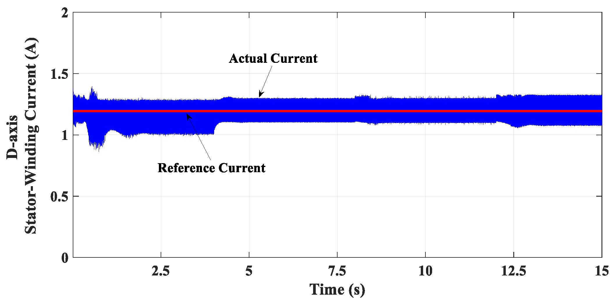
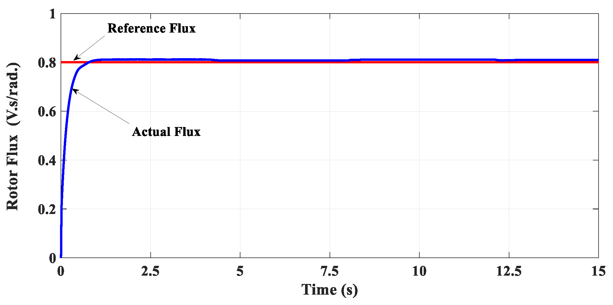
On the other hand, Figure 11 shows the response of the machine rotor flux. Furthermore, the response of the stator dq-axis current components is also shown in Figure 12 and Figure 13 respectively.
A constant level of the rotor-winding flux has been successfully observed according to the command setting value, as shown in Figure 11. In addition, it is obvious from Figure 12 that the d-axis stator-winding current component has been maintained constant at its command value which refers to the desired value of the command rotor flux, as shown in Figure 11, according to (8).
This confirms and validates the capability and effectiveness of the proposed control system to effectively estimate the correct position, for the required rotor-winding flux orientation and maintain the rotor flux at a constant command value according to the presented IRFOC scheme.
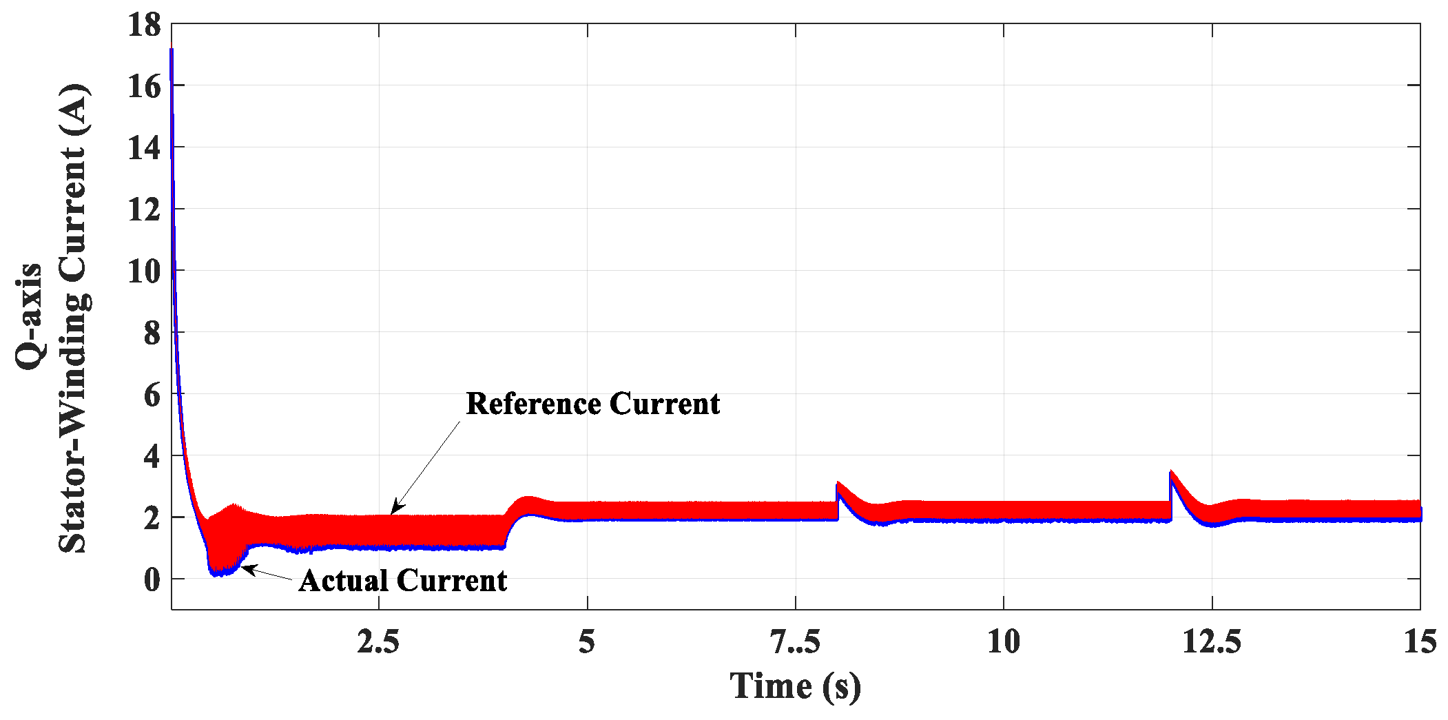
It can also be illustrated from Figure 13 that the q-axis stator-winding current component has effectively tracked its command values, which refers to its corresponding electromagnetic torque variations, shown in Figure 8, according to (7), which verifies the efficacy of the presented speed-control drive system.
The obtained results confirm the validity of the proposed rotor-speed observer for sensorless vector-control capability. Furthermore, the results verify the effectiveness of the suggested sensorless speed-control system for IM drives.
5.2. Robustness Confirmation Against Parameters Uncertainty
In order to confirm the effectiveness of the proposed new rotor-speed observer against the parameter changes of IM that affect the sensorless control procedure which has been discussed in Section 4, e.g., the variation of inductances and also the variation of IM rotor resistance some of the obtained results are introduced as shown in Figure 14, Figure 15, Figure 16, Figure 17, Figure 18 and Figure 19.
To verify the robustness of the proposed rotor-speed observer under the case of parameter variations, the results are carried out with 150% uncertainties of the whole parameters that affect the calculations of the suggested algorithm for the proposed new observer, as in Section 4.
It is obvious from Figure 14, Figure 15, Figure 16, Figure 17, Figure 18 and Figure 19 that the validity of the proposed rotor-speed observer and its capability for a sensorless speed-control system are not affected by the uncertainty issue of the adopted IM parameters, e.g., the IM inductances and also the rotor resistance. This confirms and proves the functionality and robustness of the new rotor-speed observer for a sensorless vector-control system of IM drives.
All presented results ensure the effectiveness and capability of the proposed sensorless speed-control system based on a suggested new rotor-speed observer for IM drives.
6. Experimental Work
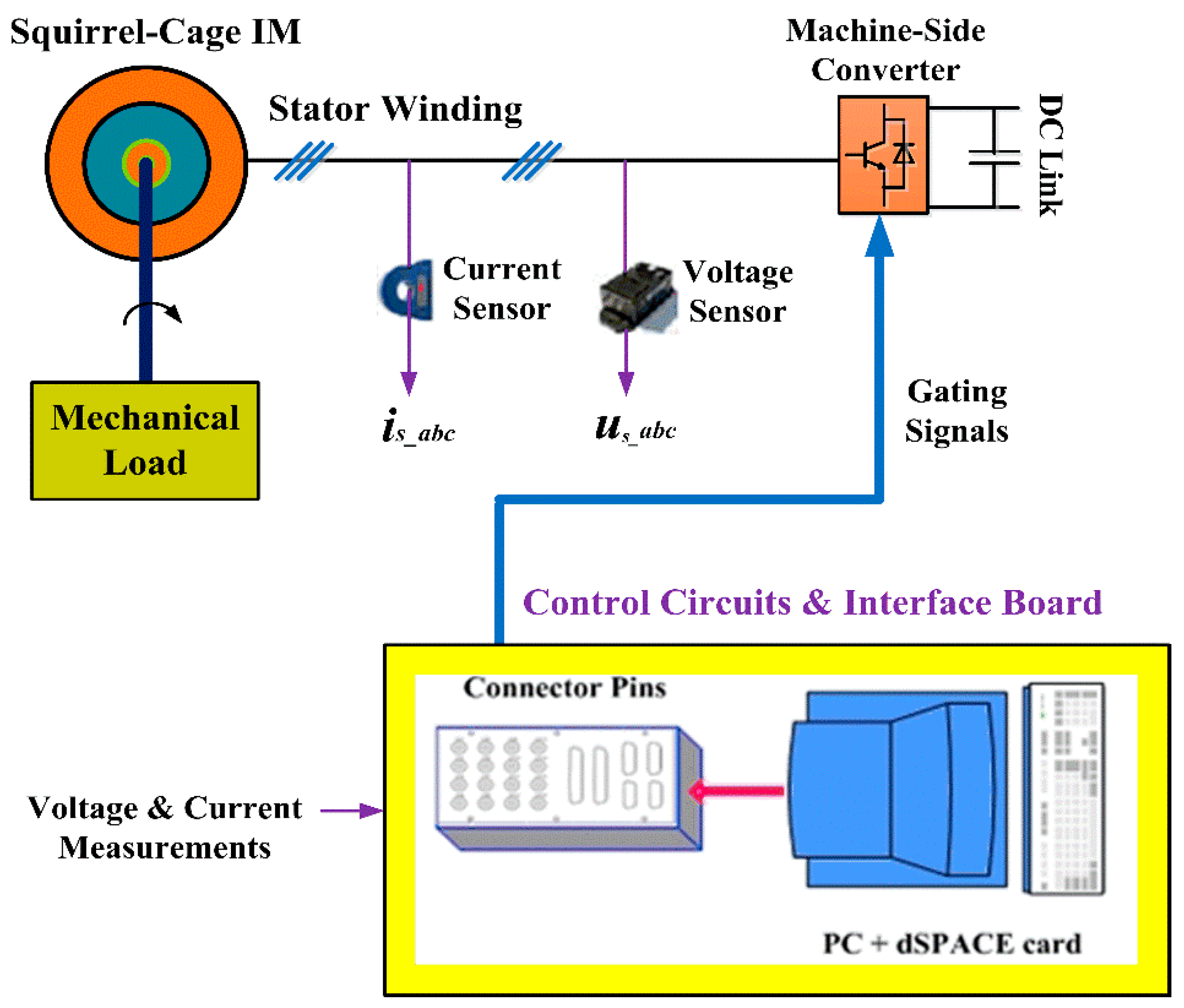
In order to confirm the efficacy of the presented sensorless control procedure, the progress towards obtaining the experimental results is completely outlined in this section which ensures the effectiveness of the suggested procedure. For this aim, the implementation process in terms of preparing the adopted IM setup and the whole control system are described with more details in this paper.
A squirrel cage induction motor is driven with a three-phase inverter whose gating signals are obtained using the control circuits implemented in dSPACE environment using a DS1104 controller board. The DS1104 board is based on the Texas Instrument TMS320F240 floating-point Digital Signal Processor (DSP) [26]. For the control purpose, voltage and current signals are measured to be used as inputs to the dSPACE environment. Therefore, the presented set-up needs some interface circuits such as voltage and current transducers. The implementation process in terms of preparing the adopted IM setup and the whole control system are shown in Figure 20.
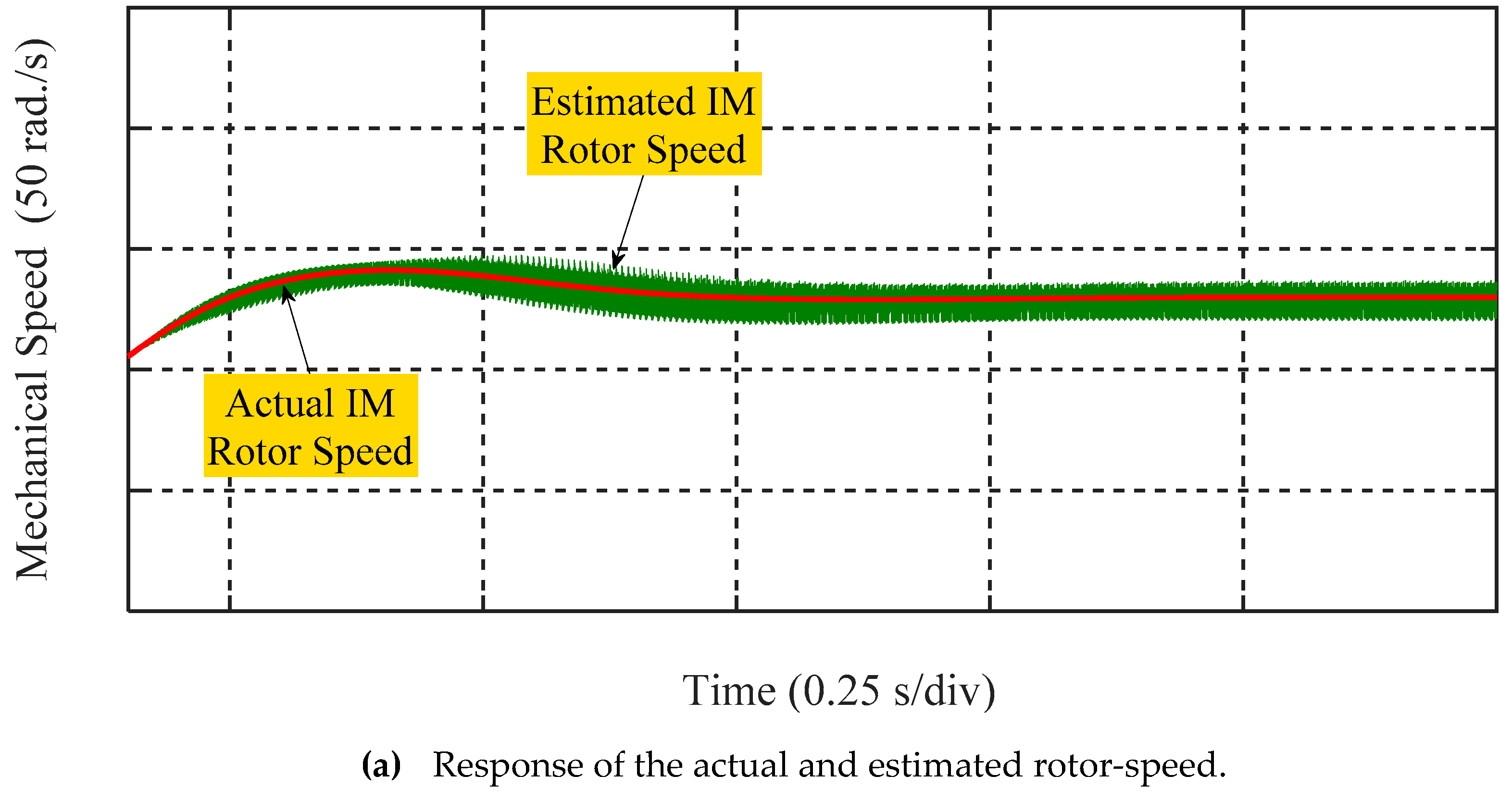
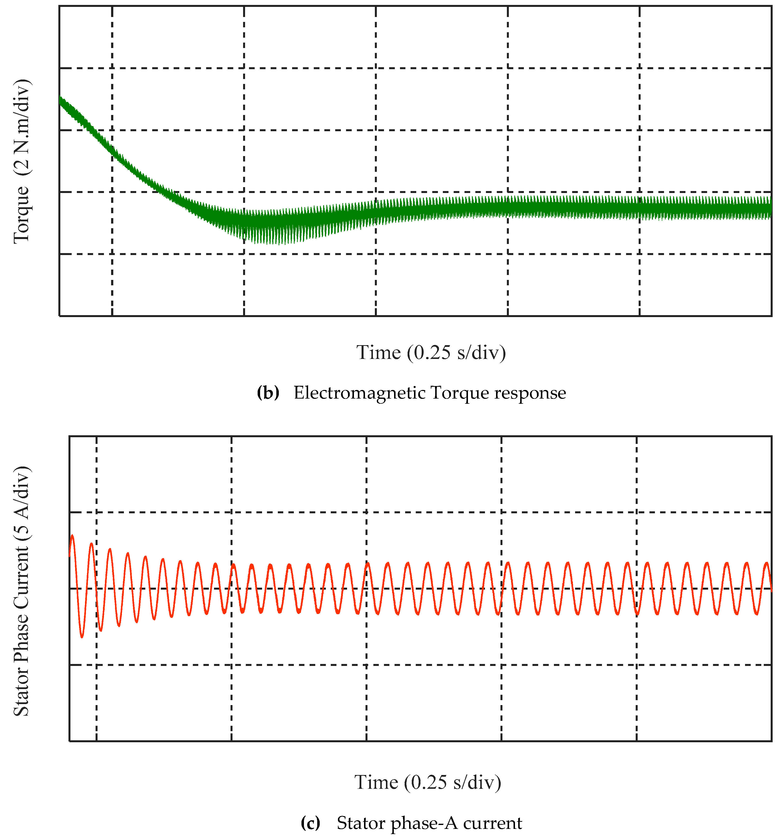
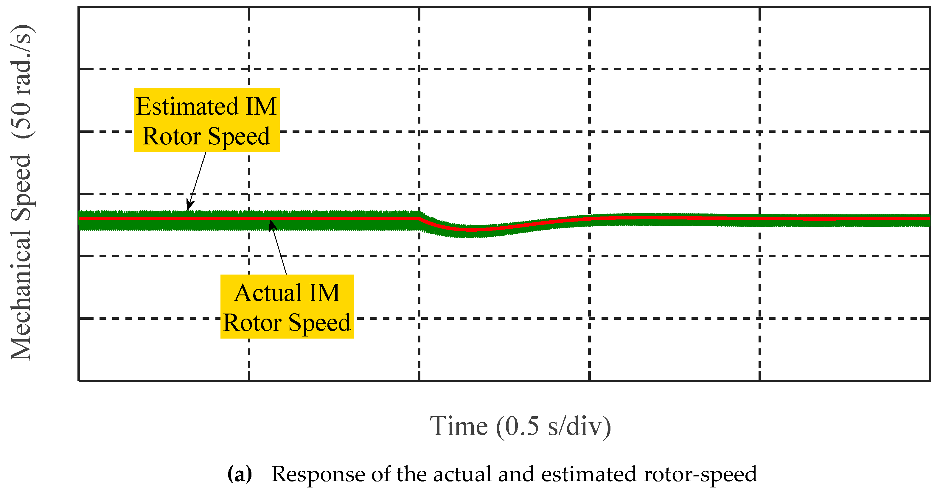
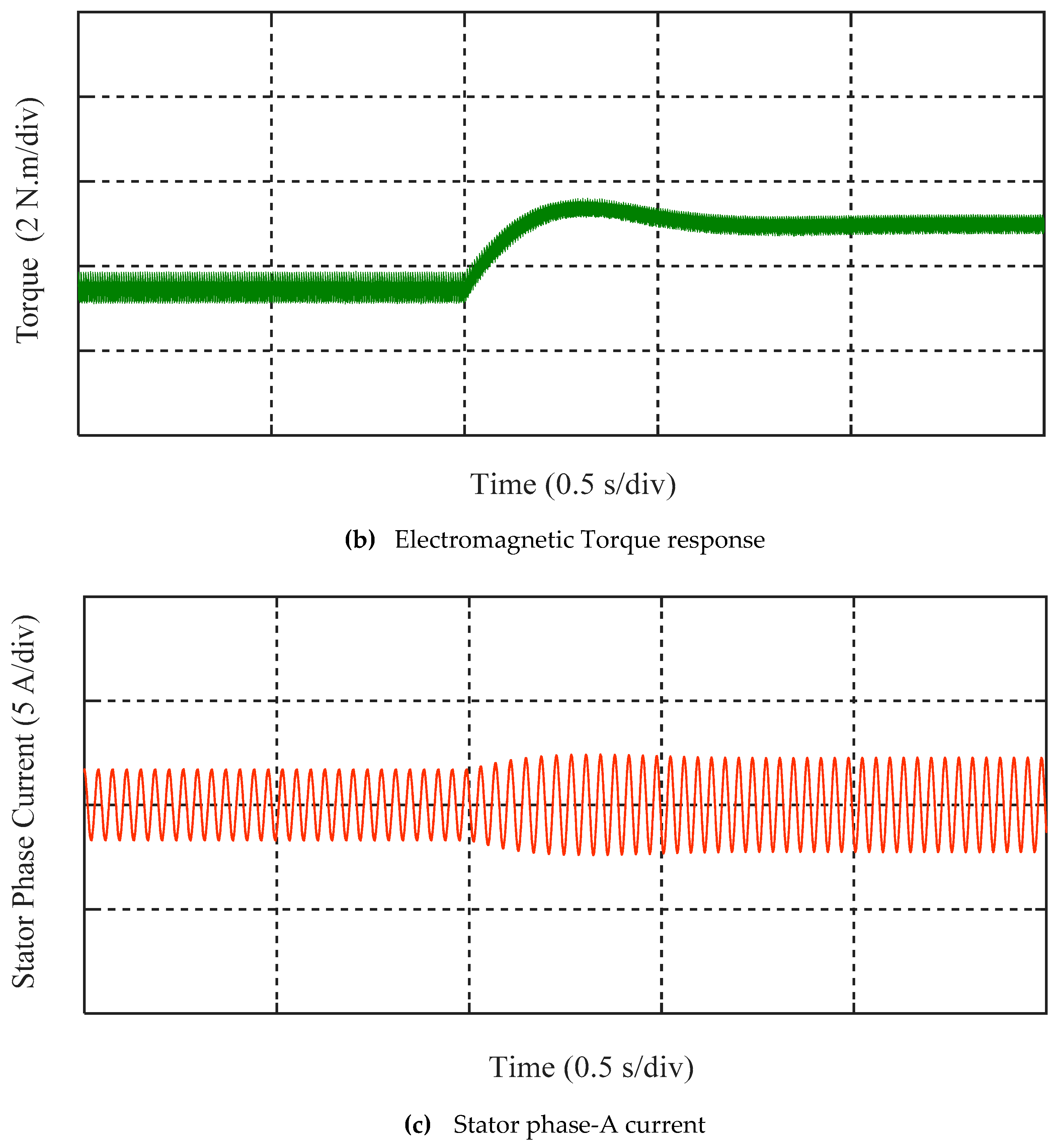
In order to investigate the adopted sensorless speed control algorithm, the presented procedure based on the proposed speed-estimation approach is tested using the adopted dSPACE environment with a set point of reference speed as shown in Figure 21 and Figure 22 for the start-up condition and the load-change operation, respectively. Figure 21 and Figure 22a–c donate the actual and estimated speed response, the electromagnetic torque, and the corresponding stator phase-A current.
After getting the estimated IM rotor-speed, a desired speed is set and compared with the predicted value, according to Figure 4, to obtain the corresponding reference torque aided with a PI controller whose gains are adjusted using the “trial and error” principle.
The adjustment of these controller gains needs to be carefully considered. In addition, the high frequency noise resulted in the estimated speed of the experimental work as in Figure 21a and Figure 22a and is to be fully eliminated in future work. However, the presented obtained results have been applied in the presented drive system application by using a suitable simple filter, which is to be addressed.
A good transient response can be observed of the stator-winding phase current under the proposed sensorless speed-control drive system as shown in Figure 21c and Figure 22c. It can also be concluded from Figure 21a and Figure 22b that the IM rotor-speed has been practically estimated with a good correlation between the actual and predicted value assuring a good transient response which ensures the efficacy and validity of the suggested speed-estimation procedure.
7. Conclusions
This paper has proposed a sensorless vector-control strategy for speed-control drive systems of IM. The proposed sensorless vector-control strategy has been based on the rotor-winding flux orientation (IRFOC method) and the validity of the machine rotor-speed estimation. In order to eliminate the complexity issues and to reduce the overall cost of the control system, the simplicity purpose of the rotor-speed estimation procedure is the main challenge for sensorless control capability of IM drive systems. This paper has attempted to fill this void by proposing a simple, more effective theoretical approach for detecting the rotor-speed signal of the adopted IM using the phase-axis relationships of the machine. The presented simulation results have confirmed the capability of the proposed control technique to estimate the correct position, that achieves the intended rotor-winding flux orientation. In addition, a close correlation between the estimated and actual IM rotor-speed has been observed, which verifies the validity of the proposed rotor-speed observer. Moreover, the obtained results ensure the capability of the presented sensorless control system for speed-control purpose. Furthermore, the results have ensured the robustness and efficacy of the proposed rotor-speed observer against parameter uncertainty issues.
Author Contributions
Conceptualization, M.G.H. and W.X.; Methodology, M.G.H.; Software, M.G.H.; Validation, M.G.H., W.X., Y.L. and S.M.A.; Formal Analysis, M.G.H.; Investigation, M.G.H.; Resources, M.G.H.; Data Curation, M.G.H.; Writing-Original Draft Preparation, M.G.H.; Writing-Review & Editing, M.G.H. and Y.L.; Visualization, M.G.H. and S.M.A.; Supervision, W.X. and Y.L.
Funding
This work has been partly supported by National Natural Science Foundation of China (NSFC 51877093 and 51707079), National Key Research and Development Program of China (Project ID: YS2018YFGH000200), and Fundamental Research Funds for the Central Universities (2019kfyXMBZ031).
Conflicts of Interest
The authors declare no conflict of interest.
Appendix A

Table A1.
Complete parameters of the adopted IM [25].
Table A1.
Complete parameters of the adopted IM [25].
| Rated Line Voltage | 400 V |
| Rated Frequency | 50 Hz |
| 5.71 Ω | |
| 4.08 Ω | |
| 14.3 mH | |
| 14.3 mH | |
| 670.5 mH | |
| Rotor Inertia, J | 0.011 kg.m2 |
References
- Wu, B.; Lang, Y.; Zargari, N.; Kouro, S. Power Conversion and Control of Wind Energy Systems; Wiley-IEEE Press: New York, NY, USA, 2011. [Google Scholar]
- Bose, B.K. Modern Power Electronics and AC Drives; Prentice Hall PTR: Saddle River, NJ, USA, 2002. [Google Scholar]
- Zeb, K.; Haider, A.; Uddin, W.; Qureshi, M.B.; Mehmood, C.A.; Jazlan, A.; Sreeram, V. Indirect Vector Control of Induction Motor using Adaptive Sliding Mode Controller. In Proceedings of the Australian Control Conference (AuCC), Newcastle, Australia, 3–4 November 2016; pp. 358–363. [Google Scholar]
- Gobinath, D.; Vairaperumal, K.; Elamcheren, S. Simplified approach on feed forward vector control of induction motor with PI controller using SPWM technique. In Proceedings of the IEEE International Conference on Computational Intelligence and Computing Research, Coimbatore, India, 18–20 December 2014; pp. 1–4. [Google Scholar]
- Saha, S.; Nayak, B. Sensorless vector control and selection of observer gain for speed control of indirect vector control induction motor drives. In Proceedings of the 2017 Second International Conference on Electrical, Computer and Communication Technologies (ICECCT), Coimbatore, Tamil Nadu, India, 22–24 February 2017; pp. 1–7. [Google Scholar]
- Griva, G.; Ilas, C.; Eastham, J.F.; Profumo, F.; Vranka, P. High performance sensorless control of induction motor drives for industry applications. In Proceedings of the Power Conversion Conference, Nagaoka, Japan, 6 August 1997; pp. 535–539. [Google Scholar]
- Rokhforoz, P.; Poshtan, J. Rotor speed and resistance estimation using robust extended Kalman filter for sensorless vector control of induction motor drives. In Proceedings of the 6th Power Electronics, Drive Systems & Technologies Conference (PEDSTC 2015), Tehran, Iran, 3–4 February 2015; pp. 304–309. [Google Scholar]
- Ha, J.; Sul, S. Sensorless field-orientation control of an induction machine by high-frequency signal injection. IEEE Trans. Ind. Appl. 1999, 35, 45–51. [Google Scholar]
- Fot, S.; Testa, A.; De Caro, S.; Scimone, T.; Scelba, G.; Scarcella, G. Rotor Time Constant Identification on Sensorless Induction Motor Drives by low Frequency Signal Injection. In Proceedings of the 2018 IEEE 9th International Symposium on Sensorless Control for Electrical Drives (SLED), Helsinki, Finland, 13–14 September 2018; pp. 150–155. [Google Scholar]
- Teja, A.; Chakraborty, C.; Maiti, S.; Hori, Y. A new model reference adaptive controller for four quadrant vector controlled induction motor drives. IEEE Trans. Ind. Electron. 2012, 59, 3757–3767. [Google Scholar] [CrossRef]
- Rind, S.; Ren, Y.; Shi, K.; Jiang, L.; Tufail, M. Rotor flux-MRAS based speed sensorless non-linear adaptive control of induction motor drive for electric vehicles. In Proceedings of the 50th International Universities Power Engineering Conference (UPEC), Stoke on Trent, UK, 1–4 September 2015. [Google Scholar]
- Rashed, M.; Stronach, A. A stable back-EMF MRAS-based sensorless low-speed induction motor drive insensitive to stator resistance variation. IEE Proc. Electr. Power Appl. 2004, 151, 685–693. [Google Scholar] [CrossRef]
- Ta, C.; Uchida, T.; Hori, Y. MRAS-based speed sensorless control for induction motor drives using instantaneous reactive power. In Proceedings of the 27th Annual Conference of IECON, Denver, CO, USA, 29 November–2 December 2001. [Google Scholar]
- Teja, A.; Verma, V.; Chakraborty, C. A new formulation of reactive-power-based model reference adaptive system for Sensorless induction motor drive. IEEE Trans. Ind. Electron. 2015, 62, 6797–6808. [Google Scholar] [CrossRef]
- Kojabadi, H. Active power and MRAS based rotor resistance identification of an IM drive. Simul. Model. Pract. Theory 2009, 17, 376–389. [Google Scholar] [CrossRef]
- Fereka, D.; Zerikat, M.; Belaidi, A. MRAS Sensorless Speed Control of an Induction Motor Drive based on Fuzzy Sliding Mode Control. In Proceedings of the 2018 7th International Conference on Systems and Control (ICSC), Valencia, Spain, 24–26 October 2018; pp. 230–236. [Google Scholar]
- Nadh, G.; Syamkumar, U.; Jayanand, B. Sliding mode observer for vector control of induction motor. In Proceedings of the International Conference on Next Generation Intelligent Systems (ICNGIS), Kottayam, India, 1–3 September 2016; pp. 1–6. [Google Scholar]
- Kouchih, D.; Hachelaf, R.; Boumalha, N.; Tadjine, M.; Boucherit, M.S. Improvement of sensorless vector controlled induction motor drives using a new algorithm for the rotor resistance adaptation. In Proceedings of the the 5th International Conference on Systems and Control (ICSC), Marrakesh, Morocco, 25–27 May 2016; pp. 67–71. [Google Scholar]
- Gadoue, S.M.; Giaouris, D.; Finch, J.W. Sensorless Control of Induction Motor Drives at Very Low and Zero Speeds Using Neural Network Flux Observers. IEEE Trans. Ind. Electron. 2009, 56, 3029–3039. [Google Scholar] [CrossRef]
- Cirrincione, M.; Pucci, M.; Cirrincione, G.; Capolino, G.A. Sensorless Control of Induction Motor Drives by New Linear Neural Techniques. In Proceedings of the 12th International Power Electronics and Motion Control Conference, Portoroz, Slovenia, 30 August–1 September 2006; pp. 1820–1829. [Google Scholar]
- Jnayah, S.; Khedher, A. Sensorless Direct Torque Control of induction motor using sliding mode flux observer. In Proceedings of the 2019 19th International Conference on Sciences and Techniques of Automatic Control and Computer Engineering (STA), Sousse, Tunisia, 24–26 March 2019; pp. 536–541. [Google Scholar]
- Zhang, Z.; Bazzi, A.M. Robust Sensorless Scalar Control of Induction Motor Drives with Torque Capability Enhancement at Low Speeds. In Proceedings of the 2019 IEEE International Electric Machines & Drives Conference (IEMDC), San Diego, CA, USA, 12–15 May 2019; pp. 1706–1710. [Google Scholar]
- Mousa, M.G.; Allam, S.M.; Rashad, E.M. A sensorless scalar-control strategy for maximum power tracking of a grid-connected wind-driven brushless doubly-fed reluctance generator. In Proceedings of the 4th International Conference on Electric Power and Energy Conversion Systems (EPECS’15), Sharjah, UAE, 24–26 Novmber 2015; pp. 1–6. [Google Scholar]
- Mousa, M.G.; Allam, S.M.; Rashad, E.M. Sensored and sensorless scalar-control strategy of a wind-driven BDFRG for maximum wind-power extraction. J. Control Decis. 2018, 5, 209–227. [Google Scholar] [CrossRef]
- Verma, V.; Maiti, S.; Chakraborty, C. Sensorless control of grid-connected doubly-fed slip-ring induction motor drive. In Proceedings of the 35th Annual Conference of IEEE Industrial Electronics, Porto, Portugal, 3–5 November 2009; pp. 1276–1281. [Google Scholar]
- Hussien, M.G.; Xu, W.; Liu, Y. Vector control schemes for direct voltage control of the stand-alone brushless doubly-fed induction generator. In Proceedings of the 2018 21st International Conference on Electrical Machines & Systems (ICEMS), Jeju, South Korea; 2018; pp. 1307–1312. [Google Scholar]
Figure 1.
Main estimation procedure for the three-phase rotor currents of the adopted IM system.

Figure 2.
Verified estimated response of the IM rotor currents compared with the corresponding actual values.
Figure 2.
Verified estimated response of the IM rotor currents compared with the corresponding actual values.

Figure 3.
IM phase-axis relations in the case of IRFOC technique.

Figure 4.
Conceptual diagram of the adopted sensorless control system.

Figure 5.
Command speed response and its corresponding actual value.

Figure 6.
Estimated and actual speed response of IM.

Figure 7.
Speed-estimation error.

Figure 8.
Electromagnetic torque response and the load torque.

Figure 9.
Stator phase-current response.

Figure 10.
Rotor phase-current response.

Figure 11.
Response of the rotor flux.

Figure 12.
Stator current d-axis component.

Figure 13.
Stator current q-axis component.

Figure 14.
Estimated and actual speed response of IM under parameter changes (150% uncertainty).

Figure 15.
Speed-estimation error under parameter changes (150% uncertainty).

Figure 16.
Electromagnetic torque response and the load torque under parameter changes (150% uncertainty).
Figure 16.
Electromagnetic torque response and the load torque under parameter changes (150% uncertainty).

Figure 17.
Stator phase-current response under parameter changes (150% uncertainty).

Figure 18.
Rotor phase-current response under parameter changes (150% uncertainty).

Figure 19.
Response of the rotor flux under parameter changes (150% uncertainty).

Figure 20.
Conceptual diagram of the adopted sensorless control system.

Figure 21.
Experimental validation of the proposed sensorless system for IM drives under the start-up condition.
Figure 21.
Experimental validation of the proposed sensorless system for IM drives under the start-up condition.


Figure 22.
Experimental validation of the proposed sensorless system for IM drives under the load change condition.
Figure 22.
Experimental validation of the proposed sensorless system for IM drives under the load change condition.


© 2019 by the authors. Licensee MDPI, Basel, Switzerland. This article is an open access article distributed under the terms and conditions of the Creative Commons Attribution (CC BY) license (http://creativecommons.org/licenses/by/4.0/).
Share and Cite
MDPI and ACS Style
Hussien, M.G.; Xu, W.; Liu, Y.; Allam, S.M. Rotor Speed Observer with Extended Current Estimator for Sensorless Control of Induction Motor Drive Systems. Energies 2019, 12, 3613. https://doi.org/10.3390/en12193613
AMA Style
Hussien MG, Xu W, Liu Y, Allam SM. Rotor Speed Observer with Extended Current Estimator for Sensorless Control of Induction Motor Drive Systems. Energies. 2019; 12(19):3613. https://doi.org/10.3390/en12193613
Chicago/Turabian StyleHussien, Mohamed G., Wei Xu, Yi Liu, and Said M. Allam. 2019. "Rotor Speed Observer with Extended Current Estimator for Sensorless Control of Induction Motor Drive Systems" Energies 12, no. 19: 3613. https://doi.org/10.3390/en12193613
Note that from the first issue of 2016, this journal uses article numbers instead of page numbers. See further details here.