Practical Implementation of the Backstepping Sliding Mode Controller MPPT for a PV-Storage Application

1
LANSER Laboratory/CRTEn B.P.95 Hammam-Lif, Tunis 2050, Tunisia
2
Research unit: LISIER, National Higher Engineering School of Tunis, Tunis 2050, Tunisia
*
Author to whom correspondence should be addressed.
Energies 2019, 12(18), 3539; https://doi.org/10.3390/en12183539
Submission received: 26 June 2019
/
Revised: 14 July 2019
/
Accepted: 17 July 2019
/
Published: 16 September 2019
(This article belongs to the Special Issue Methods, Algorithms and Circuits for Photovoltaic Systems Diagnosis and Control)
Abstract
:This study presents a design and an implementation of a robust Maximum Power Point Tracking (MPPT) for a stand-alone photovoltaic (PV) system with battery storage. A new control scheme is applied for the boost converter based on the combination of the adaptive perturb and observe fuzzy logic controller (P&O-FLC) MPPT technique and the backstepping sliding mode control (BS-SMC) approach. The MPPT controller design was used to accurately track the PV operating point to its maximum power point (MPP) under changing climatic conditions. The presented MPPT based on the P&O-FLC technique generates the reference PV voltage and then a cascade control loop type, based on the BS-SMC approach is used. The aims of this approach are applied to regulate the inductor current and then the PV voltage to its reference values. In order to reduce system costs and complexity, a high gain observer (HGO) was designed, based on the model of the PV system, to estimate online the real value of the boost converter’s inductor current. The performance and the robustness of the BS-SMC approach are evaluated using a comparative simulation with a conventional proportional integral (PI) controller implemented in the MATLAB/Simulink environment. The obtained results demonstrate that the proposed approach not only provides a near-perfect tracking performance (dynamic response, overshoot, steady-state error), but also offers greater robustness and stability than the conventional PI controller. Experimental results fitted with dSPACE software reveal that the PV module could reach the MPP and achieve the performance and robustness of the designed BS-SMC MPPT controller.
1. Introduction
Most of our electricity needs are met by non-renewable resources which are depleting at a rapid rate. The increasing population and growing needs of energy sources present a motive to look for potential alternatives. In this regard, the production of photovoltaic (PV) energy has drawn a tremendous amount of interest. However, PV energy is still considered expensive and reducing the cost of PV systems has become a main topic of extensive research. To solve the problems above, maximising PV output power can be approached via power electronics [1,2]. The use of MPPT controller for a PV application is crucial to increasing the efficiency and the performance of a PV system [3]. The most used batteries are the lead–acid type, due to their significant autonomy and their reliable and low-cost technology. These rechargeable electrochemical devices are widely employed in many applications such as PV storage systems [1,4,5]. Several MPPT methods have been attempted to track the MPP in PV systems such as perturb and observe (P&O) [6,7], the incremental conductance (INC) method [8,9,10], the neural network controller (NNC) [11] and the fuzzy logic controller (FLC) [12,13,14]. The control parameter of the P&O technique is perturbed due to a small variation of the step size. The direction of step size caused by this algorithm is varied due to the measurement of the output power of the PV array. The disturbance of the system depends on the increase or the decrease of power [9]. The increment conductance (IC) technique is based on determining the operating point of the PV module. This method tries to raise the operating point of the PV generator until reaching the MPP. It enables a search of the MPP according to the equality of the conductance and its increment [9,10].
The most commonly employed methods in the literature are the P&O [6] and IC [9], due to the ease of both their understanding and implementation. However, these methods are not efficient during the rapid changing of climatic conditions. Furthermore, even in stable climatic conditions, they produce oscillations around the MPP and they are totally dependent on solar irradiation. In fact, the performance of these methods decreases with the decrease of solar irradiation [9].
The FLC provides the best performance compared to conventional P&O and IC techniques. However, the limitation of this technique comes from its non-achievement of sufficient accuracy of the operating point of the PV generator for the MPP. The step duty cycle changes direction according to the direction change of the adjusted power [15]. Their inputs and outputs depend entirely on the information about the system model to be studied by the designer [16].
Other techniques have been designed such as the MPPT, which is based on the dedicated sliding mode controller for PV storage systems [17,18]. This approach is of great importance given its several advantages such as stability, robustness against the parameter variation, fast dynamic response and the simplicity of implementation [19,20]. However, the SMC-MPPT approach, when applied to the dc–dc converter, has certain drawbacks, including the variability of the operating frequency in the output of the control (chattering phenomenon) [17,21,22,23,24]. This study [25] presents an experimental validation of a new SMC for a two-level voltage source inverter for a grid connected PV system. A combination of a traditional MPPT P&O technique and an SMC has been developed in [26]. Similarly, in [27], the authors suggest a backstepping sliding mode control (BS-SMC) scheme to improve the PV system. The MPP seeking method is employed to estimate the reference PV voltage. Then a cascade control loop with a BS-SMC controller aims to regulate the PV voltage to its reference values in order to monitor exactly the PV operating point under variations of the atmospheric conditions.
Moreover, the Hall Effect current sensor is used to measure the inductor current via the Hall Effect, to generate a voltage which is exactly proportional to the current to be measured or visualized. Due to the high sensitivity of this type of sensor to external or parasitic magnetic fields, the measurement of the inductor current can be erroneous. Thus, the performance of the MPPT controller could be reduced [21,28]. Conventional MPPT techniques use Hall Effect sensors and include additional circuitry such as signal conditioning buffers, filters, and amplifier circuits. This increases the cost and complexity and affects the performance system. Unfortunately, once the sensor is damaged, the operation of a photovoltaic generator will be interrupted.
Herein, based on the motivation above, we propose an MPPT based on BS-SMC to enhance the performance and the robustness of the PV storage system. The BS-SMC MPPT method is the combination between the backstepping method and sliding mode. The aim of this approach is to force the system state to achieve the MPP with a high tracking performance and stability. The convergence of the dynamics of the system around the sliding surface depends on two criteria which have been already proposed by Utkin [29] and proved by the Lyapunov function. This method is considered as a potential approach in various applications due to its robustness, its easy implementation and its ability to reject disturbances. This method is presented in reference [30], to control the attitude and position of a quadrotor unmanned aerial vehicle (UAV). The obtained results suggest its relevant performance and robustness, urging its use for the control of the dc–dc boost converter in PV storage system. However, in [27], the authors combined an extremum seeking control method to reach the PV reference voltage with the BS-SMC approach. This method shows these limits underlined by the curve of the sliding surface during variations in climatic conditions. It can be seen in this curve large-amplitude chattering phenomena. In another study [31], an MPPT controller was proposed, based on the combination of the regression plane method and a backstepping controller with integral action (IBS) to control a dc–dc buck boost converter. This technique does not take into account the faults or malfunctioning of the PV module. In addition, IBS provides a minimum of error in the stable state, without satisfying the feature of robustness.
The main goal of this study is to design a new switching function based on Lyapunov stability, to overcome the drawbacks associated with control time and reduce the cost of the PV system. In this context, there are many approaches to mitigating the disadvantages of chattering in SMC, such as using a regular approximation of the switching element or using a higher order sliding mode control (HOSMC) strategy [32].
However, using a continuous approximation affects system performance and requires finite time convergence sliding mode control. In HOSMC, it is generally difficult to estimate the high-order state derivatives and it still presents chattering in the presence of parasitic dynamics. In this study, using a sliding surface including a time function, large-amplitude chattering phenomena are attenuated and thus, robustness is ensured.
The designed MPPT controller is developed to a PV system, including a PV module, a dc–dc boost converter and a battery load. The principle of the studied control scheme contains two cascade control loops. The outer control loop based on the P&O-FLC is used to estimate the real-time of the reference voltage, which corresponds to the maximum power. The inner control loop regulates the PV voltage to reach the value of the reference voltage estimated by the outer control loop. In the absence of the inductor current sensor, the BS-SMC approach is used to track the MPP under solar irradiation and temperature variation, while the estimation of the inductor current of the dc–dc boost converter is carried out by an HGO, as shown in Figure 1. On the other hand, the estimated current is used in the input of the BS-SMC.
After a general introduction, this article first details the modelling of the PV storage system, the design of the BS-SMC controller and the HGO, then the stability analysis. Secondly, we are interested in comparing the simulation results of the proposed BS-SMC controller with the conventional PI controller. The experimental results are illustrated, explained and discussed in detail in the third section. Finally, this paper is completed by a conclusion and perspectives.
2. Modelling of the PV System
Figure 2 shows the proposed configuration of the photovoltaic (PV) storage system which consists of a PV module, a dc–dc boost converter and a battery load.
2.1. Modelling of PV Module
The expression of the solar PV cell terminal current as a function of the photo-current, the diode current and the shunt current, can be expressed by:
where is the photocurrent of the cell, (A). is the saturation current of the P–N junction and is the current through the parallel resistor .
The output current of PV array can be given by:
where Is is cell reverse saturation current; q is the electron charge ; is the Boltzman constant ; n is ideality factor solar cell; is the output voltage; is the number of PV cells connected in parallel; is the number of PV cells connected in series; and are the series and shunt resistors of the PV array, respectively.
The cell reverse saturation current can be determined by:
where is the band gap energy of the semi conductor used in the cell and is the cell reference temperature.
The reverse saturation current at can be calculated by:
where is the cell short-circuit at reference temperature and solar irradiance and the open circuit voltage is .
The photocurrent is related to the solar irradiation and temperature; its expression is obtained by the following equation:
where is the short circuit current temperature coefficient and is the solar irradiance.
The monocrystalline Solo Line LX-100M model has been chosen in this paper. The specification parameters of the PV module are presented in Table 1.
The characteristic I_V and P_V curves of the PV module for different values of solar irradiation E and temperatures T are illustrated in Figure 4a,b, respectively.
Figure 4a,b depict the general appearance of the electrical characteristics of a PV generator for different values of temperature and solar irradiation. It can be noted that with the increasing temperature, the generated current increases slightly. Inversely, the open circuit voltage decreases considerably. It can be observed that the variation of the solar irradiation greatly affects the short circuit, with low impact on the open circuit voltage. Consequently, the variation of MPP depends on the solar irradiation.
2.2. Modelling of the DC–DC Boost Converter
The block diagram of the dc–dc boost converter is illustrated in Figure 5. It is used to adjust the PV voltage to its reference value corresponding to the MPP.
The system dynamics are described by the following equations [1,9,17,22,33,34,35]:
where , and represent the average output voltage, the input voltage and the average inductor current during the switching period, respectively; is the filter inductor; is the input capacitor; is the output capacitor and is the load battery.
3. Controller Design and Stability Analysis
The block diagram of the proposed BS-SMC is shown in Figure 2. For each value of solar irradiation and of cell temperature , the block adaptive P&O-FLC enables the provision of an on-line calculation of the reference photovoltaic voltage . The control signal corresponds to the MPP and is generated from block BS-SMC controller.
3.1. Adaptive P&O–FLC
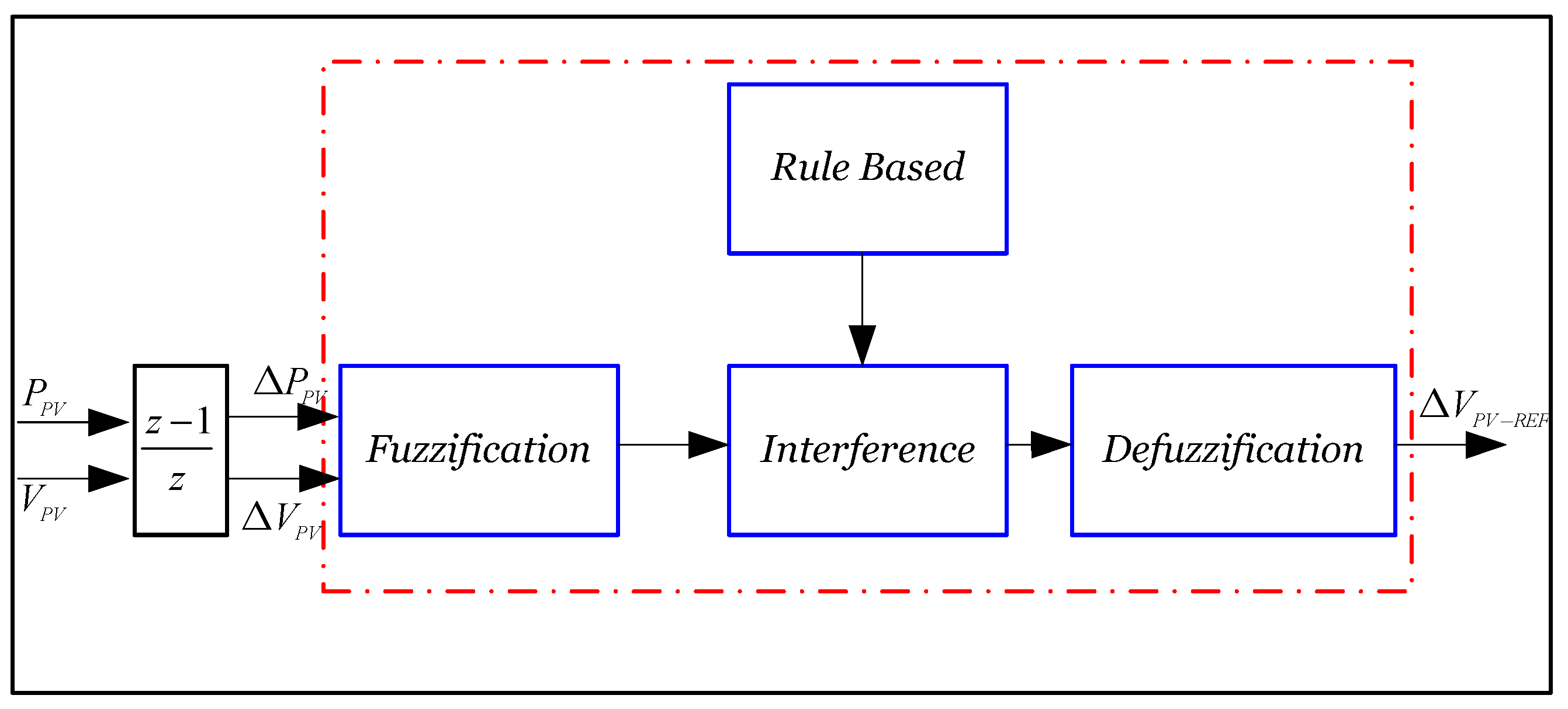
The differential power and the differential voltage are used as inputs of the adaptive P&O-FLC algorithm. is determined through an FL approach whose block diagram is presented in Figure 6 [33].
The functional diagram of the P&O-FLC is presented in Figure 7.
The five proposed variables are very small, small, medium, large and very large. The input membership function of the PV power is the difference between the current power and the previous power. In addition, the difference between the current voltage and the previous voltage is the input membership function of the PV voltage . Then, the difference between the current maximum PV output voltage and the previous maximum PV output voltage is the output membership function of the reference voltage . The two memberships functions and are converted to linguistic variables after their calculation. Then the output is generated by searching in a rule base table, consisting of 25 rules. A Mamdani’s method is performed to determine the output of this algorithm [15,34,36,37].
3.2. Observer Design
The average model of the dc–dc boost converter can be deduced as follows:
where represents the average inductor current and denotes the average PV voltage.
The state observer is designed based on the PV system module in order to estimate the state of the inductor current, which enables the application of the proposed BS-SMC MPPT. The estimated state vector is obtained by the state observer, in which the dynamics of the averaged state-space model should behave similarly to those of the real model.
The observer error between the real and the estimated states is defined as [21,22,28]. The proposed HGO can be written as:
Where , and denote an observer gain matrix chosen through analysing the stability of the proposed closed-loop system [38,39].
It can be noted that the HGO dynamics associated with the PV system are as follows:
The voltage and current control errors between the reference and the estimated values are represented by defining the dynamic errors as :
It can be observed from Equation (10) that the estimation error can be given in the following form:
If is a Hurwitz matrix, we can guarantee the convergence of asymptotic errors; consequently, .
The gains of the HGO can be selected as below:
where the constants , and are definite positive.
3.3. Backstepping Sliding Mode Controller Design
The suggested MPPT controller is designed for the target that the voltage of the VPV panel follows its reference value corresponding to the voltage at MPP of the PV panel [40]. This purpose is achieved by acting on the duty cycle α of the boost type dc–dc convertor.
Firstly, the voltage tracking error between and is defined by:
The derivative with regard to the time of e1 is given by:
Considering the first Lyapunov candidate function as follows:
Time derivative of is given by:
In the case that is negative, we have:
where is a constant positive definite.
The second Lyapunov function is selected as follows:
where S is the sliding surface given by:
Consider the candidate Lyapunov function positive definite. The derivative with respect to time of the Lyapunov function is obtained through the following equation:
where is given as follows:
We consider the dynamics of the sliding surface as follows [27]:
where q0 and q1 are positive constants.
The expression for the control input deduced from Equations (23) and (24) by considering , can be determined as:
3.4. Stability Analysis
To prove the stability of and , we have resorted to the Barbalat’s Lemma.
Barbalat’s Lemma:
If the differentiable functionhas a finite limit asand ifis uniformly continuous (oris bounded), then we haveas.
By exploiting Equations (19), (22) and (24), the following equation can be obtained:
In order to make , the constants , and should be positive.
4. Simulation Results
This section is dedicated to the simulation results of the BS-SMC scheme applied to the boost dc–dc converter for the PV storage system as exhibited in Figure 2. To demonstrate the superiority of the proposed BS-SMC, a comparison simulation with a conventional PI controller has been established under a MATLAB/Simulink package with the SimPower Toolbox. In order to point out the strengths and shortcomings of every controller, the two procedures are performed under similar tests conditions. The simulations were done with the sampling time of 100 μs for the global PV model. A monocrystalline Solo Line LX-100M model PV generator is used in this work with a peak of power of 100 W under standard test conditions (STC), such as a fixed value of solar radiation (E = 1 kW/m2) and a fixed temperature (T = 25 °C). Table 1 shows the electrical parameters of the single PV, whereas the specifications of the controller parameters and the dc–dc boost converter are summarized in Table 2.
The storage device is a lead–acid battery of the PowerSafe TS range. It can reach 5200 cycles to a depth of discharge of 25%. The main characteristics of fully charged elements at a temperature of 25 °C are shown in Table 3.
The simulation results are evaluated according to three cases. The first case study is to evaluate the system performance of the proposed control during the system operation in STC. The second case consists of disrupting the climatic condition profile by comparing its performance with the PI controller technique. The third one is devoted to examining the function of the system in varying climatic conditions by introducing the observer studied.
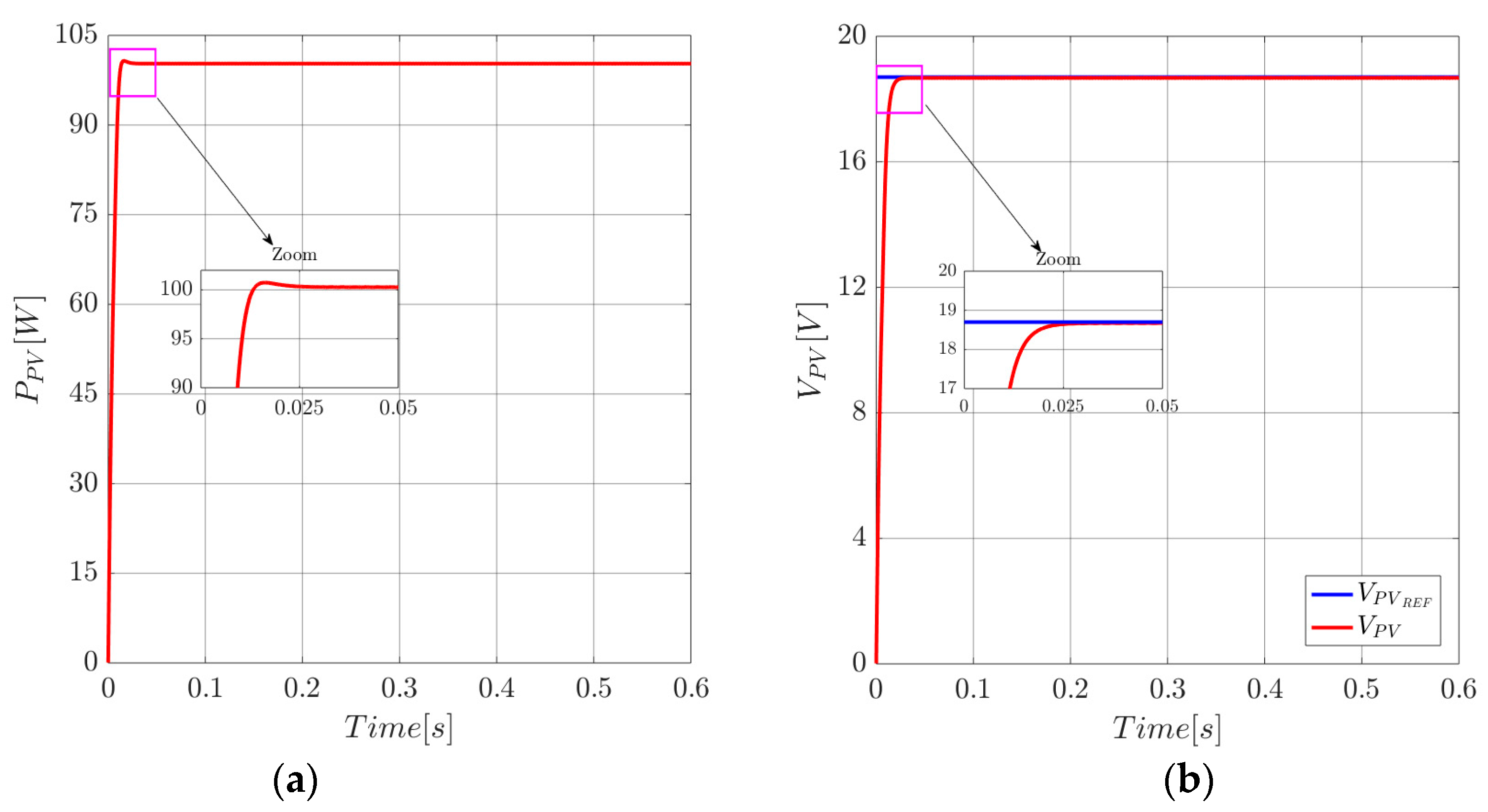
Case 1: Standard operating conditions.
The first simulation section focused on the tracking performance under constant climatic conditions (E = 1 kW/m2 and T = 25 °C). The results of the voltage evolution and active power curves’ response for the PV system are obtained by the proposed BS-SMC, as shown in Figure 8a, b. It can be seen from Figure 8b that the voltage follows its reference imposed by the adaptive P&O-FL MPPT technique with a fast setting time (around 27 ms), less dynamic error and any overshoot. It can be noted from Figure 8a that the MPPT based on BS-SMC applied in the boost dc–dc converter operates the power of the PV generator to MPP (100W). Furthermore, Figure 9a illustrates the performances of the inductor current with the presented control technique. Obviously, the proposed control using BS-SMC for the boost dc–dc converter stabilizes the PV output current to the optimal value with faster dynamic response, less overshoot and high precision and stability. Figure 10a,b show the convergence of the dynamic error and the sliding surface signal to zero. It can be concluded from this figure that the designed BS-SMC presents a good transition response, limits the chattering phenomenon and provides a good tracking performance.
Case 2: Variation of solar irradiation and temperature.
The second simulation section is devoted to the control of the boost dc–dc converter using the proposed MPPT approach in case of changes in weather conditions, as shown in Figure 11a,b.
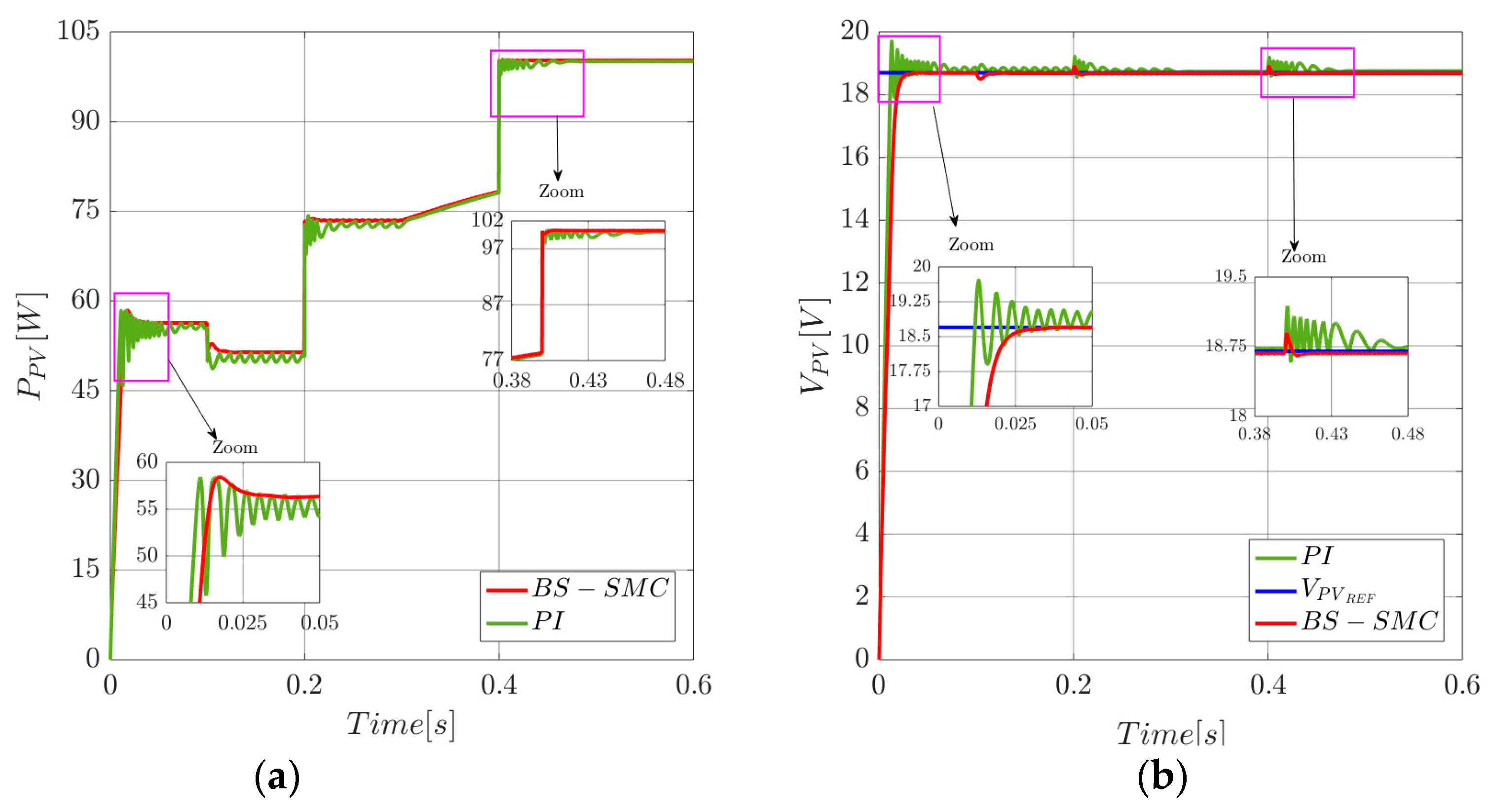
The results of the evolution of voltage, current and power curves’ responses are obtained by using a PI controller which has been compared with the proposed BS-SMC in Figure 12, Figure 13 and Figure 14. It can be observed that the classical PI controller is dictated by the variation of solar irradiance and external disturbances, while the system controlled by the BS-SMC is more robust to variation in weather conditions. The proposed control ensures a better dynamic response and robustness under the solar irradiance changes during this test. The power, voltage and current results of the PV panel are presented in Figure 12a,b and Figure 13a, respectively.
According to Figure 12b, the P&O-FLC successfully generates the tracking of the MPP which is successfully tracked through the BS-SMC controller. Furthermore, in Figure 12a we can see that in specific situations when the irradiation rose from 0 to 600 W/m2, the designed algorithm worked well with low solar irradiation and resulted in negligent power losses. It can also be observed that BS-SMC has a fast dynamic response with very low oscillation and stability.
Figure 12a shows that the power increases under a different level of the solar irradiance and temperature, due to increases in the current and voltage of the panel. On the other hand, in order to confirm the performance of the BS-SMC approach, Figure 12, Figure 13 and Figure 14 present a comparative study between the proposed controller and the conventional PI controller [9,17,40]. This comparison is according to weather condition as presented in Table 4.
During this experiment, it is noteworthy that the system follows the reference under 10.95 ms faster with a steady state error to zero using the BS-SMC where there are strong oscillations in the PI controller. In addition, the point at maximum power is reached with almost negligible ripple in less than 2.8825 W. Moreover, the boost dc–dc converter successfully extracts maximum power with more than 99.4% efficiency. Also, when the solar irradiance and temperature are kept at 1 kW/m2 and 25 °C, successively, the average output power is equal to 100.1 W. Compared with the PI controller, the power increases by about 2% of the value obtained by the proposed controller. Moreover, these comparisons confirm the relevance and benefit of the presented control strategies in terms of the voltage monitoring of the PV model at the MPP.
A zoomed view of the oscillations around the MPP using the PI controller is presented in Figure 12b. It is clear from this figure that the ripples output voltage of the proposed controller is much lower than that of the PI controller.
According to climatic condition variation, the proposed BS-SMC controller proves its robustness, which reduces the chatter phenomenon, as shown in Figure 14b. In fact, the strategy proposed by BS-SMC offers better dynamic performance than that used by the conventional PI control method.
Case 3: Application of HGO under solar irradiation and temperature variation.
In this case, the performance of the presented BS-SMC at tracking the MPP without the use of inductor current sensors is evaluated as a function of solar irradiance and temperature variations.
The profiles of the climatic conditions in this simulations study are presented in Figure 11a,b.
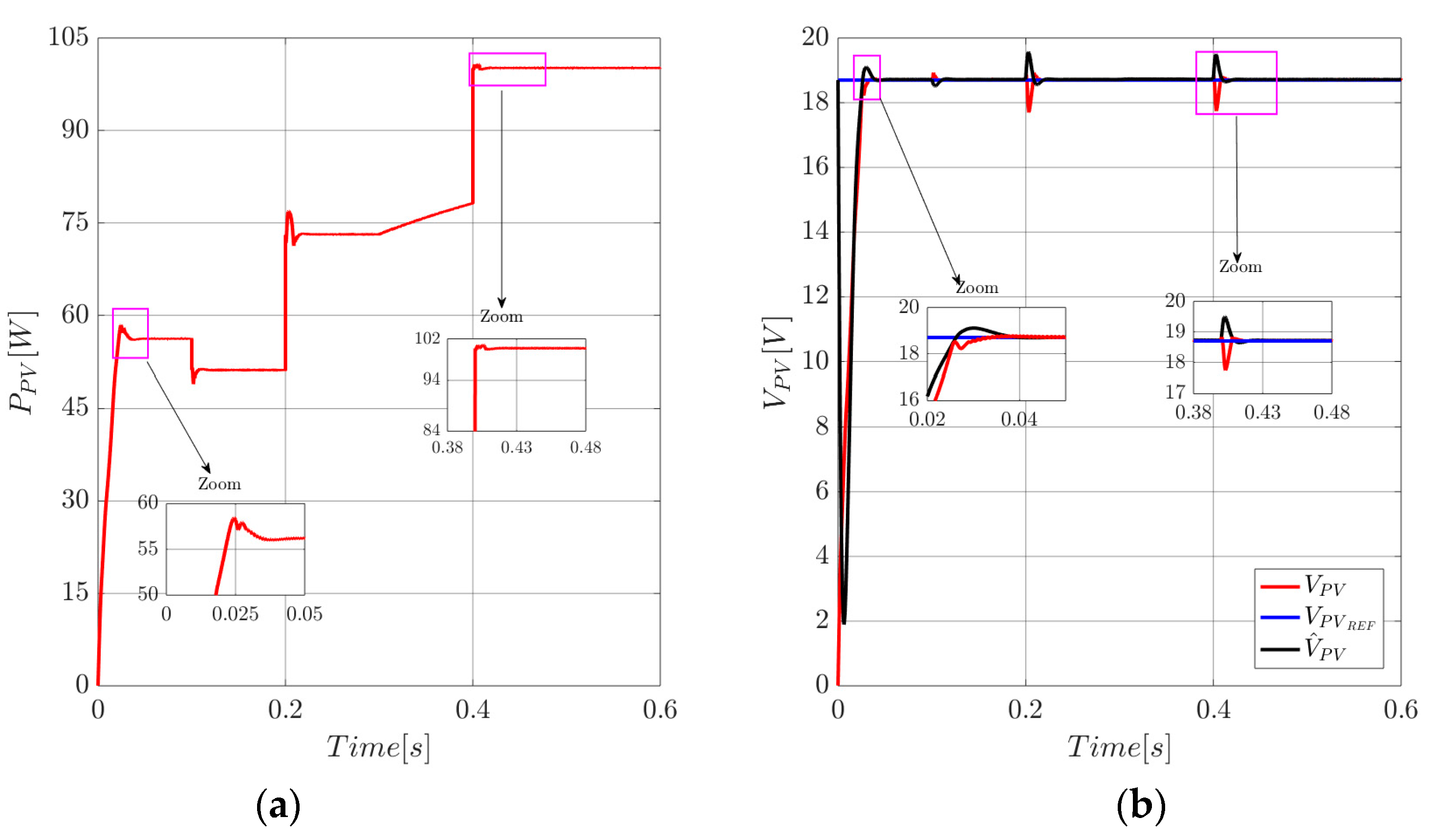
Figure 15, Figure 16 and Figure 17 show the dynamic performance of the tracker at varying irradiance and temperature. It is clearly shown from Figure 15a that the designed sensor-less MPPT does not exhibit much oscillation around the MPP.
For more details, the key figures obtained for the BS-SMC controller without inductor current sensors are shown in Table 5.
Figure 16 shows the error between the inductor current and it is estimated to be almost equal zero.
Figure 15b shows that when the estimation state starts in the observer reel state, there is an instantaneous estimation error of the voltage which is rapidly reduced to zero during the estimation process.
In Figure 16, it can be noted that the HGO has better performance by comparing the measurements of the inductor current with the estimation. The choice of gains and confirm the correct operation of the observers as the estimated current correctly tracks the real state in less than 0.036 s, under an initial solar irradiance and temperature of 600 W/m2 and 25 °C, respectively.
In Figure 15b, we can see that the transient response time is very short when a sudden change in solar irradiance and temperature occur at t = 9.75 ms, revealing the best dynamic performance of the BS-SMC approach. It can be noticed that, at the moment of the step change of the weather conditions, the voltage of the PV generator can be stabilized to its reference value. In addition, the BS-SMC strategy provides a stable power proportional to the irradiation and temperature levels, at a response time of the order of 1 ms when the solar irradiation E rises from 800 W/m2 to 1000 W/m2 with the temperature maintained at 25 °C. Figure 15a presents the power of the PV module. From this figure, some fluctuations are recorded which are ascribed to the dynamics of the observer.
As seen in Figure 15a,b, the MPP is successfully tracked and the PV voltage is stabilized at the reference value. Hence, it is obvious, by examining Figure 15b and Figure 16, that both the PV voltage and the inductor current have smaller overshoots. For example, when the solar irradiance and temperature are kept at 1 kW/m2 and 25 °C, respectively, in this case, and the estimated inductor current and the PV voltage have an overshoot of approximately 0.03 A and 0.9 V, respectively. It can be seen that the proposed state observer-based control algorithm is able to force the PV generator to operate at MPP using only three sensors to measure voltage and current.
In the sliding surface mode, a phenomenon known as chattering can take place. It is manifested by high-frequency switching around the sliding surface. These commutations can excite unwanted dynamics that may destabilize damage or even destroy the studied system.
This chattering phenomenon is limited by the introduced BS-SMC controller, as shown in Figure 18 which demonstrates the efficiency of this approach.
5. Experimental Results and Discussion
An experimental model has been presented and analyzed on a more sophisticated test bench for a standalone PV system in the CRTEn research laboratory located in the technology park of Borj Cedrya Tunisia at latitude 36.717° and longitude 10.427°. The prototype built consists of a BP Solar LX-100M photovoltaic panel, a dc–dc boost converter and a lead acid type battery load, as illustrated in Figure 19. The PV storage system is controlled by a Control Engineering DS 1104 board through a Matlab/Simulink environment.
The block diagram of the proposed BS-SMC approach has been implemented to generate the pulse with modulation (PWM) signal for acting on the MOSFET gate of the dc–dc boost converter, as seen in Figure 20. The parameters of the PV storage system are presented in Table 2 and the switching frequency of the boost converter is chosen to be 25 kHz. The sampling time of the system is chosen with the performance of controller board at s. The BP Solar LX-100M PV panel with an angle of 37° has the parameters presented in Table 1.
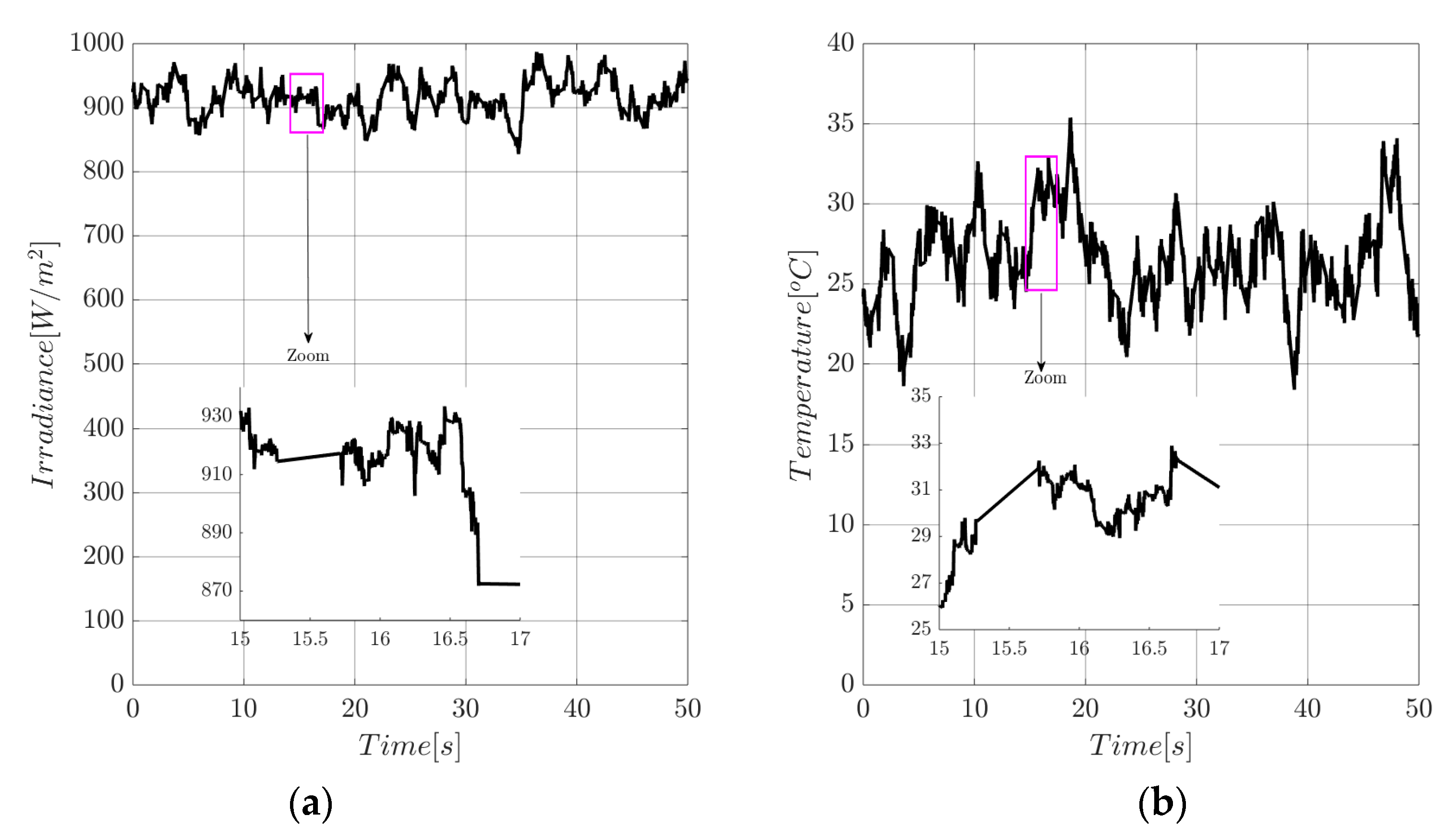
The data acquisition of the input voltage and the input current for the test bench comes from LEM sensors LV25-P and LA25-P, respectively. These serve as inputs to the interface of the dSPACE 1104 while the PWM output signal generated from the DS 1104 varies between 0 and 5 V. To amplify the output voltage to a voltage sufficient to the MOSFET (10V), an amplifier circuit is constructed. When the pulses are amplified, they go through an isolated circuit to separate the supply circuit and the control circuit. Control Desk software is used to monitor the displacement of the MPP on the P–V characteristics under changing climatic conditions. To reduce unwanted high-frequency noise from current and voltage measurements during acquisition, low-pass filters have been designed. Given the absence of a PV emulator, the results are presented based on real-time temperature and solar irradiation measurement data, as shown in Figure 21 and Figure 22.
The block diagram implantation of the proposed approach given in Figure 2 is used to confirm the real time simulation. It can be seen that the proposed MPPT has been implemented using the DS1104 platform.
To evaluate and verify the efficiency of the proposed MPPT method based on the BS-SMC controller, experimental results were obtained in the Dspace 1104 card. Figure 22, Figure 23 and Figure 24 show the experimental results of the voltage, current and power of the PV module and inductor current by using the proposed MPPT approach.
During the interval time s, the maximum irradiance and temperature level are and T = 30.18 °C, respectively. In this condition, the optimal current and voltage of the PV module are about 3.92 A and 18.24 V, respectively. Then, the maximum PV power is around 77.51 W. Table 6 shows clearly that the presented scheme is characterized by negligible overshoot and permanent low voltage ripples comparing with the results obtained in [36].
It can be noted from these results that the MPP is always achieved. The validation of the robustness of the proposed BS-SMC in the presence of temperature and solar irradiation variation is guaranteed. From the experimental measurements presented in Figure 22 and Figure 23, we can see small oscillations around the average value of the PV output voltage, power and current, respectively. The characteristics P_V and I_V curves of the PV module under weather conditions’ variation are shown in Figure 25. This confirms that the MPP voltage is only affected by fast-varying solar irradiance.
According to the experimental results, it is concluded that, under varying irradiation and temperature conditions, the system using the proposed approach is able to operate MPP accurately, and offers better stability and insignificant steady state error. Interestingly, the observed inductor current has some minimal error between the experimental results and the estimated state by the HGO, as illustrated in Figure 24.
6. Conclusions
In this paper, we have presented and analyzed a robust BS-SMC controller to track the MPP of a stand-alone PV system. The proposed approach is performed to regulate the PV module output voltage to its reference trajectory obtained by the adaptive P&O-FLC technique. The maximum PV output power is achieved under changing climatic conditions. The Lyapunov stability analysis is used to verify the global asymptotic stability of the PV system. The simulation and experimental results under changing climatic conditions show the performance and the robustness of the MPPT controller. In addition, the presented technique performs better when compared with the classical PI controller. In fact, the simulation and experimental results confirm the efficiency of the HGO. The BS-SMC controller is simple to design and easy to implement in a real-time application. The major contributions of our study are as follows: reducing the required sensor by using HGO, reducing the chattering phenomenon by using the BS-SMC approach, the successful implementation of the BS-SMC controller in a dSPACE1104 card and the successful application of the dSPACE-based controller to control the PV storage application with a robust control performance. Future work can focus on the application of the proposed BS-SMC to other dc–dc converters with battery loads such as buck converters; and discretization of the proposed MPPT controller can also be investigated. Work is currently in progress and the results will be reported in due course.
Author Contributions
M.B. proposed the main idea, performed the investigation and developed the software; M.M., B.K. and R.B. collaborated to achieve the work; A.S. led the project and acquired the funds for research.
Funding
This research was funded by LANSER Laboratory/CRTEn B.P.95 Hammam-Lif 2050, Tunis, Tunisia.
Conflicts of Interest
The authors declare no conflict of interest.
References
- Zaouche, F.; Rekioua, D.; Gaubert, J.-P.; Mokrani, Z. Supervision and control strategy for photovoltaic generators with battery storage. Int. J. Hydrogen Energy 2017, 42, 19536–19555. [Google Scholar] [CrossRef]
- Mohapatra, A.; Nayak, B.; Das, P.; Mohanty, K.B. A review on MPPT techniques of PV system under partial shading condition. Renew. Sustain. Energy Rev. 2017, 80, 854–867. [Google Scholar] [CrossRef]
- Ali, N.; Armghan, H.; Ahmad, I.; Armghan, A.; Khan, S.; Arsalan, M. Backstepping based non-linear control for maximum power point tracking in photovoltaic system. Sol. Energy 2018, 159, 134–141. [Google Scholar]
- Azzollini, I.A.; Di Felice, V.; Fraboni, F.; Cavallucci, L.; Breschi, M.; Rosa, A.D.; Zini, G. Lead-Acid Battery Modeling Over Full State of Charge and Discharge Range. IEEE Trans. Power Syst. 2018, 33, 6422–6429. [Google Scholar] [CrossRef]
- Spanos, C.; Turney, D.E.; Fthenakis, V. Life-cycle analysis of flow-assisted nickel zinc-, manganese dioxide-, and valve-regulated lead-acid batteries designed for demand-charge reduction. Renew. Sustain. Energy Rev. 2015, 43, 478–494. [Google Scholar] [CrossRef]
- Rezkallah, M.; Hamadi, A.; Chandra, A.; Singh, B.; Hamadi, A. Design and Implementation of Active Power Control With Improved P&O Method for Wind-PV-Battery-Based Standalone Generation System. IEEE Trans. Ind. Electron. 2018, 65, 5590–5600. [Google Scholar]
- Kihal, A.; Krim, F.; Laib, A.; Talbi, B.; Afghoula, H. An improved MPPT scheme employing adaptive integral derivative sliding mode control for photovoltaic systems under fast irradiation changes. ISA Trans. 2018, 87, 297–306. [Google Scholar] [CrossRef]
- Zakzouk, N.E.; Williams, B.W.; Helal, A.A.; Elsaharty, M.A.; Abdelsalam, A.K. Improved performance low-cost incremental conductance PV MPPT technique. IET Renew. Power Gener. 2016, 10, 561–574. [Google Scholar] [CrossRef]
- Bounechba, H.; Bouzid, A.; Snani, H.; Lashab, A. Real time simulation of MPPT algorithms for PV energy system. Int. J. Electr. Power Energy Syst. 2016, 83, 67–78. [Google Scholar] [CrossRef] [Green Version]
- Koohi-Kamali, S.; Rahim, N.; Mokhlis, H. Smart power management algorithm in microgrid consisting of photovoltaic, diesel, and battery storage plants considering variations in sunlight, temperature, and load. Energy Convers. Manag. 2014, 84, 562–582. [Google Scholar] [CrossRef]
- Messalti, S.; Harrag, A.; Loukriz, A. A new variable step size neural networks MPPT controller: Review, simulation and hardware implementation. Renew. Sustain. Energy Rev. 2017, 68, 221–233. [Google Scholar] [CrossRef]
- Mhamed, F.; Mohamed Larbi, E.; Smail, Z. Hardware implementation of the fuzzy logic MPPT in an Arduino card using a Simulink Support Package for photovoltaic application. IET Renew. Power Gener. 2018, 13, 510–518. [Google Scholar]
- Reddy, K.J.; Sudhakar, N. ANFIS-MPPT control algorithm for a PEMFC system used in electric vehicle applications. Int. J. Hydrogen Energy 2019, 44, 15355–15369. [Google Scholar] [CrossRef]
- Shah, N.; Rajagopalan, C. Experimental evaluation of a partially shaded photovoltaic system with a fuzzy logic-based peak power tracking control strategy. IET Renew. Power Gener. 2016, 10, 98–107. [Google Scholar] [CrossRef]
- Farajdadian, S.; Hosseini, S.H. Design of an optimal fuzzy controller to obtain maximum power in solar power generation system. Sol. Energy 2019, 182, 161–178. [Google Scholar] [CrossRef]
- Ahmad Khateb, M.N. Fuzzy logic controller based sepic converter for maximum power point tracking. IEEE Trans. Ind. Appl. 2016, 50, 2349–2358. [Google Scholar] [CrossRef]
- El Khazane, J.; Tissir, E.H. Achievement of MPPT by finite time convergence sliding mode control for photovoltaic pumping system. Sol. Energy 2018, 166, 13–20. [Google Scholar] [CrossRef]
- Ya-Ting, L.; Chian-Song, C.; Tse-Wei, C. Maximum power point tracking of grid-tied photovoltaic power systems. In Proceedings of the 2014 International Power Electronics Conference, Hiroshima, Japan, 18–21 May 2014; pp. 440–444. [Google Scholar]
- Yatimi, H.; Aroudam, E. Assessment and control of a photovoltaic energy storage system based on the robust sliding mode MPPT controller. Sol. Energy 2016, 139, 557–568. [Google Scholar] [CrossRef]
- Yasin, A.R.; Ashraf, M.; Bhatti, A.I. A Novel Filter Extracted Equivalent Control Based Fixed Frequency Sliding Mode Approach for Power Electronic Converters. Energies 2019, 12, 853. [Google Scholar] [CrossRef]
- Yang, B.; Yu, T.; Shu, H.; Zhu, D.; An, N.; Sang, Y.; Jiang, L. Perturbation observer based fractional-order sliding-mode controller for MPPT of grid-connected PV inverters: Design and real-time implementation. Control Eng. Pract. 2018, 79, 105–125. [Google Scholar] [CrossRef]
- Keshari, K.; Neeli, S.; Vijayakumar, K. Design of a sliding-mode-controlled dc-dc converter for MPPT in grid-connected PV System. In Proceedings of the 2017 IEEE International Conference on Electrical, Instrumentation and Communication Engineering (ICEICE), Karur, India, 27–28 April 2017; pp. 1–8. [Google Scholar]
- Pradhan, R.; Subudhi, B. Double Integral Sliding Mode MPPT Control of a Photovoltaic System. IEEE Trans. Control Syst. Technol. 2016, 24, 1. [Google Scholar] [CrossRef]
- Belkaid, A.; Gaubert, J.-P.; Gherbi, A. Design and implementation of a high-performance technique for tracking PV peak power. IET Renew. Power Gener. 2017, 11, 92–99. [Google Scholar] [CrossRef]
- Cortajarena, J.A.; Barambones, O.; Alkorta, P.; De Marcos, J. Sliding mode control of grid-tied single-phase inverter in a photovoltaic MPPT application. Sol. Energy 2017, 155, 793–804. [Google Scholar] [CrossRef]
- Montoya, D.G.; Ramos-Paja, C.A.; Giral, R.; Ramos, C. Improved design of sliding mode controllers based on the requirements of MPPT techniques. IEEE Trans. Power Electron. 2016, 31, 1. [Google Scholar] [CrossRef]
- Dahech, K.; Allouche, M.; Damak, T.; Tadeo, F. Backstepping sliding mode control for maximum power point tracking of a photovoltaic system. Electr. Power Syst. Res. 2017, 143, 182–188. [Google Scholar] [CrossRef]
- Das, D.; Madichetty, S.; Singh, B.; Mishra, S. Luenberger Observer Based Current Estimated Boost Converter for PV Maximum Power Extraction-A Current Sensorless Approach. IEEE J. Photovolt. 2019, 9, 278–286. [Google Scholar] [CrossRef]
- Kumari, S. Decentralized SoC based Droop with Sliding Mode Current Controller for DC Microgrid. In Proceedings of the 2018 5th IEEE Uttar Pradesh Section International Conference on Electrical, Electronics and Computer Engineering (UPCON), Gorakhpur, India, 2–4 November 2018. [Google Scholar]
- Chen, F.; Jiang, R.; Zhang, K.; Jiang, B.; Tao, G. Robust Backstepping Sliding Mode Control and Observer-based Fault Estimation for a Quadrotor UAV. IEEE Trans. Ind. Electron. 2016, 63, 5044–5056. [Google Scholar] [CrossRef]
- Arsalan, M.; Iftikhar, R.; Ahmad, I.; Hasan, A.; Sabahat, K.; Javeria, A. MPPT for photovoltaic system using nonlinear backstepping controller with integral action. Sol. Energy 2018, 170, 192–200. [Google Scholar] [CrossRef]
- Kchaou, A.; Naamane, A.; Koubaa, Y.; M’Sirdi, N. Second order sliding mode-based MPPT control for photovoltaic applications. Sol. Energy 2017, 155, 758–769. [Google Scholar] [CrossRef]
- Bjaoui, M.; Khiari, B.; Benadli, R.; Memni, M.; Sellami, A. Maximum Power Point Tracking of a photovoltaic pumping system with PSO controller design. In Proceedings of the 4th International Conference on Green Energy and Environmental Engineering (GEEE), Sousse, Tunisia, 22–24 April 2017. [Google Scholar]
- Abu Eldahab, Y.E.; Saad, N.H.; Zekry, A. Enhancing the design of battery charging controllers for photovoltaic systems. Renew. Sustain. Energy Rev. 2016, 58, 646–655. [Google Scholar] [CrossRef]
- Viloria-Porto, J.; Robles-Algarín, C.; Restrepo-Leal, D. A Novel Approach for an MPPT Controller Based on the ADALINE Network Trained with the RTRL Algorithm. Energies 2018, 11, 3407. [Google Scholar] [CrossRef]
- Zainuri, M.A.A.M.; Rahim, N.A.; Soh, A.C.; Radzi, M.A.M. Development of adaptive perturb and observe-fuzzy control maximum power point tracking for photovoltaic boost dc–dc converter. IET Renew. Power Gener. 2014, 8, 183–194. [Google Scholar] [CrossRef]
- Yilmaz, U.; Kircay, A.; Borek+ci, S. PV system fuzzy logic MPPT method and PI control as a charge controller. Renew. Sustain. Energy Rev. 2018, 81, 994–1001. [Google Scholar] [CrossRef]
- Cho, H.; Yoo, S.J.; Kwak, S. State observer based sensor less control using Lyapunov’s method for boost converters. IET Power Electron. 2015, 8, 11–19. [Google Scholar] [CrossRef]
- Cimini, G.; Ippoliti, G.; Orlando, G.; Longhi, S.; Miceli, R. A unified observer for robust sensorless control of DC–DC converters. Control Eng. Pract. 2017, 61, 21–27. [Google Scholar] [CrossRef]
- Anto, E.K.; Asumadu, J.A.; Okyere, P.Y. PID control for improving P&O-MPPT performance of a grid-connected solar PV system with Ziegler-Nichols tuning method. In Proceedings of the 2016 IEEE 11th Conference on Industrial Electronics and Applications (ICIEA), Hefei, China, 5–7 June 2016; pp. 1847–1852. [Google Scholar]
Figure 1.
Control scheme of the PV storage system.

Figure 2.
Diagram of the PV storage system.

Figure 3.
Equivalent circuit model of the PV cell.

Figure 4.
Characteristic curves of PV array obtained under weather conditions: (a) I_V characteristic curves; (b) P_V characteristic curves.
Figure 4.
Characteristic curves of PV array obtained under weather conditions: (a) I_V characteristic curves; (b) P_V characteristic curves.

Figure 5.
Circuit diagram of dc-dc boost converter.

Figure 6.
Block diagram of the adaptive perturb and observe fuzzy logic controller algorithm.

Figure 7.
Flow chart of the adaptive P&O-FLC.

Figure 8.
PV array output power and voltage under standard condition: (a) the PV power curve; (b) tracking of with respect to .
Figure 8.
PV array output power and voltage under standard condition: (a) the PV power curve; (b) tracking of with respect to .

Figure 9.
Maximum Power Point Tracking in standard operating conditions: (a) PV array output current; (b) duty cycle .
Figure 9.
Maximum Power Point Tracking in standard operating conditions: (a) PV array output current; (b) duty cycle .

Figure 10.
MPPT performance: (a) evolution of error ; (b) sliding surface .

Figure 11.
Varying level of weather conditions: (a) solar irradiance profile; (b) temperature profile.
Figure 11.
Varying level of weather conditions: (a) solar irradiance profile; (b) temperature profile.

Figure 12.
Comparison of tracking MPP of BS-SMC and PI controller under varying solar irradiance and temperature. (a) PV array output power; (b) tracking of with respect to .
Figure 12.
Comparison of tracking MPP of BS-SMC and PI controller under varying solar irradiance and temperature. (a) PV array output power; (b) tracking of with respect to .

Figure 13.
MPPT tracking under varying weather conditions: (a) PV array output current; (b) duty cycle .
Figure 13.
MPPT tracking under varying weather conditions: (a) PV array output current; (b) duty cycle .

Figure 14.
MPPT performance under a step change of the climatic conditions: (a) dynamic evolution of error ; (b) dynamic evolution of sliding surface .
Figure 14.
MPPT performance under a step change of the climatic conditions: (a) dynamic evolution of error ; (b) dynamic evolution of sliding surface .

Figure 15.
PV array output power and voltage under varying solar irradiance and temperature without sensor inductor current: (a) PV array output power; (b) tracking of with respect to .
Figure 15.
PV array output power and voltage under varying solar irradiance and temperature without sensor inductor current: (a) PV array output power; (b) tracking of with respect to .

Figure 16.
Inductor current without sensors.

Figure 17.
MPPT tracking under conditions climatic variations without sensor inductor current: (a) PV array output current; (b) duty cycle .
Figure 17.
MPPT tracking under conditions climatic variations without sensor inductor current: (a) PV array output current; (b) duty cycle .

Figure 18.
MPPT performance under a step change in the solar irradiance and temperature without sensor inductor current: (a) dynamic evolution of error ; (b) dynamic evolution of sliding surface .
Figure 18.
MPPT performance under a step change in the solar irradiance and temperature without sensor inductor current: (a) dynamic evolution of error ; (b) dynamic evolution of sliding surface .

Figure 19.
Experimental test bench.

Figure 20.
Block diagram implementation of the proposed BS-SMC MPPT.

Figure 21.
Experimental results of climatic conditions variation: (a) experimental solar irradiance profile; (b) experimental temperature profile.
Figure 21.
Experimental results of climatic conditions variation: (a) experimental solar irradiance profile; (b) experimental temperature profile.

Figure 22.
Experimental PV array output power and voltage under varying solar irradiance and temperature without sensor inductor current: (a) PV array output power; (b) tracking of with respect to .
Figure 22.
Experimental PV array output power and voltage under varying solar irradiance and temperature without sensor inductor current: (a) PV array output power; (b) tracking of with respect to .

Figure 23.
Experimental results of the output PV current.

Figure 24.
Experimental results of the inductor current estimation.

Figure 25.
PV array output characteristic curves: (a) characteristic curves of the PV module; (b) characteristic curves of the PV module.
Figure 25.
PV array output characteristic curves: (a) characteristic curves of the PV module; (b) characteristic curves of the PV module.


Table 1.
Parameters of the Solo Line LX-100M PV panel under standard test conditions (STC).
| Parameter | Name | Value |
|---|---|---|
| Maximum Power | 100 Wp | |
| Voltage at maximum power | 18.7 V | |
| Current at maximum power | 5.39 A | |
| Open circuit voltage | 21.6 V | |
| Short circuit current | 5.87 A | |
| Temperature coefficient of ISC | 1.73 mA/°C | |
| Number of cells per module | 60 |
Table 2.
Simulation parameters.
| Parameter | Name | Value |
|---|---|---|
| Input capacitor | 2200 μF | |
| Inductor | 5 mH | |
| Output capacitor | 4700 μF | |
| MOSFET switching frequency | 25 kHz | |
| sliding surface | 10 | |
| sliding surface | 1 | |
| Gain of observer | 60 | |
| Gain of observer | 20 |
Table 3.
Lead acid battery parameters.
| Parameter | Name | Value |
|---|---|---|
| Nominal capacity | 390 Ah | |
| Internal resistor | 0.64*12(7.68 mΩ) | |
| Nominal voltage | 12*2 V(24 V) |
Table 4.
Performance comparison of the BS-SMC and PI controller.
| Controller | Power Overshoot (%) | Power Ripple (W) | Response Time (ms) | Power Extraction Efficiency (%) |
|---|---|---|---|---|
| PI | 1.68 | 6.1575 | 47.775 | 98 |
| BS-SMC | 1.6 | 2.8825 | 10.95 | 99.4 |
Table 5.
Performance of the BS-SMC without sensor inductor current.
| Algorithm | Power Overshoot (%) | Power Ripple (W) | Response Time (ms) | Power Extraction Efficiency (%) |
|---|---|---|---|---|
| BS-SMC | 3.44 | 2.745 | 9.75 | 99.79 |
Table 6.
Experiment performance of the BS-SMC.
| Power Overshoot | Power Ripple | |
|---|---|---|
| PV power | 1.5% | 2.2 W |
| PV voltage | 0.7% | 0.32 V |
© 2019 by the authors. Licensee MDPI, Basel, Switzerland. This article is an open access article distributed under the terms and conditions of the Creative Commons Attribution (CC BY) license (http://creativecommons.org/licenses/by/4.0/).
Share and Cite
MDPI and ACS Style
Bjaoui, M.; Khiari, B.; Benadli, R.; Memni, M.; Sellami, A. Practical Implementation of the Backstepping Sliding Mode Controller MPPT for a PV-Storage Application. Energies 2019, 12, 3539. https://doi.org/10.3390/en12183539
AMA Style
Bjaoui M, Khiari B, Benadli R, Memni M, Sellami A. Practical Implementation of the Backstepping Sliding Mode Controller MPPT for a PV-Storage Application. Energies. 2019; 12(18):3539. https://doi.org/10.3390/en12183539
Chicago/Turabian StyleBjaoui, Marwen, Brahim Khiari, Ridha Benadli, Mouad Memni, and Anis Sellami. 2019. "Practical Implementation of the Backstepping Sliding Mode Controller MPPT for a PV-Storage Application" Energies 12, no. 18: 3539. https://doi.org/10.3390/en12183539
Note that from the first issue of 2016, this journal uses article numbers instead of page numbers. See further details here.