Experimental Investigations of Flow Field and Atomization Field Characteristics of Pre-Filming Air-Blast Atomizers

1
University of Chinese Academy of Sciences, Beijing 100190, China
2
Key Laboratory of Light-Duty Gas-Turbine, Institute of Engineering Thermophysics, Beijing 100190, China
*
Author to whom correspondence should be addressed.
Energies 2019, 12(14), 2800; https://doi.org/10.3390/en12142800
Submission received: 3 July 2019
/
Revised: 16 July 2019
/
Accepted: 17 July 2019
/
Published: 20 July 2019
Abstract
:Flow field, atomization field characteristics, and liquid film breakup behaviors of a pre-filming air-blast atomizer are investigated using PIV (Particle Imaging Velocimetry), PLIF (Fuel Planar Laser Induced Fluorescence), and high-speed shadowgraph technique under different air mass rates (ma), fuel mass rates (mf), and fuel temperatures (T). The influence of structures constituting the pre-filming air-blast atomizer on the flow field organization and atomization field organization are investigated too. The results illustrate that air-blast atomizer structures have a great difference on the flow fields and atomization fields. Air-blast atomizer structures have great differences on the liquid film breakup processes too. Flow field structure and atomization structure are mainly determined by the swirler structure, whereas there are seldom influences of air mass rate and fuel mass rate on them. The results of the mechanisms of flow field organization and atomization field organization in this study can be used to support the design of new low-emission combustor.
1. Introduction
Improving combustion efficiency and decreasing emission pollution are urgent needs with the increase of stringent regulations on pollutant emissions [1,2]. Pre-filming air-blast atomizers are widely applied in low-emission combustors, in which the flow field organization and the spray organization determine the combustion efficiency and emissions. Pre-filming air-blast atomizers have many advantages over traditional atomizers, especially operating at high pressure and under sub-atmospheric conditions [3,4].
Many researchers have carried out a lot of studies on the flow field, and atomization performance of pre-filming air-blast atomizers. Wang et al., Fu et al., and Colby et al. studied the effects of structure parameters on the atomization and flow field characteristics, including flare geometry, confinement, and swirl angle, etc. [5,6,7,8]. Mongia [9] studied the downstream spray field of a swirl cup combustor using PLIF technology and the results showed that venturi can control the area of fuel distribution, and form a typical cone distribution. Hadef [10] researched the effect of co- and counter-swirl on the atomization characteristics, which indicated that it was better and more spatially dispersed when using the counter-swirl. The above leads to easier ignition and lower pollutant emissions, which is also good to improve the combustion efficiency. Liu et al. [11] used PIV and PLIF technology to investigate the flow field and spray field of a three-swirl combustor under non-reacting conditions, and analyzed how the venturi angle and main swirl angle influence the flow field and spray field. The results show that the cone angle increases with venturi angle under the same pressure drop. In this paper, case D, as shown in Figure 1 is the pilot swirler of this three-swirl combustor.
The atomization process is divided into the primary breakup and the second breakup: The primary breakup is that the liquid film breaks into liquid ligaments, in which the shear force plays a major role; the second breakup is that the liquid ligaments break into large droplets, in which the surface tension plays a major role [12,13,14]. Liquid film breakup length is the key parameter of the primary atomization, where the liquid film breaks into ligaments and droplets. In addition, the nozzle structure, the physical properties of the gas and liquid, and the flow field of the gas and liquid are the main parameters to influence the liquid film breakup length [14,15]. The research on liquid film breakup is useful to learn the atomization process.
Roudini and Wozniak [16] studied the influence of the nozzle geometry. A wide range of test conditions on the spray performance of pre-filming atomizers and liquid film breakup mechanisms close to the atomizer exit were investigated using a shadowgraph associate with particle tracking. Garai and Pal [17] studied the atomization characteristics of a gas turbine hybrid atomizer, where kerosene and ethanol blended kerosene were used, analyzing the spray cone angle, liquid film breakup length, and the liquid film width.
Nowadays, a pre-filming air-blast atomizer is widely used in low-emission combustors, in which more than 60% of the total air goes through the dome, inducing the poor ignition and flameout, especially under sub-atmospheric conditions. Relight at high altitude is still a challenging issue, in which the flow field and atomization field play a major role. Although a lot of researches have been done on the pre-filming air-blast atomizer, there are seldom studies on the influence of low fuel temperature on the flow field and atomization field. In addition, the influence of structures constituting the pre-filming air-blast atomizer on the flow field organization and atomization field organization is not clearly.
In this paper, RP3 aviation kerosene is used to test a pre-filming air-blast atomizer under different air mass rates (ma), fuel mass rates (mf), and fuel temperatures (T). The influence of structures constituting the pre-filming air-blast atomizer on the flow field organization and atomization field organization are investigated. The high-speed shadowgraph technique is used to study the liquid film breakup process. The PIV and PLIF technologies are used to study the flow field and atomization field.
2. Experimental Method
2.1. Swirler Structures
To study the influence of structures constituting the pre-filming air-blast atomizer on the flow field organization and atomization field organization, the pre-filming air-blast atomizer is split into four different air-blast atomizers, as shown in Figure 1b. Case A consists of a pressure-swirl atomizer (as shown in Figure 1a) and one-stage rotating axial swirler. Case B consists of a pressure-swirl atomizer, one-stage rotating axial swirler, and a venturi tube. The swirl angle is 40°. The minimum diameter (d) of the venturi tube is 7.6 mm, and the venturi expansion angle (α) is 50°. Case C consists of a pressure-swirl atomizer, a venturi tube, and two-stage counter-rotating axial swirlers. Case D consists of a pressure-swirl atomizer, a venturi tube, and two-stage counter-rotating axial swirlers with a sleeve. Case D is the pilot stage of a low-emission combustor. The first-stage swirler is clockwise, and the second swirler is counterclockwise. In addition, the second swirler exit is longer than the venturi tube exit, we cannot see the liquid film breakup process from the venturi tube exit using Case C. In this paper, we mainly used case B to investigate the influence of air mass rate (ma), fuel mass rate (mf), and fuel temperature (T) on flow field, atomization field, and liquid film breakup process, whereas we have also done experiments under different conditions using Case C/D. The results of Case C/D are the same with those of Case B, so not discussed in this paper.
2.2. Experimental System
Schematic of the high-speed shadowgraph experiment system is shown in Figure 2. The experimental system consists of the fuel/air supplying systems, fuel cooler, measuring system, spray chamber, fuel–air separator, and shadowgraph system. The fuel supplying system consists of the fuel tank, vessel, and pump. The measuring system consists of the pressure sensor, temperature sensor, and mass flowmeter. The fuel–air separator consists of the centrifugal fan and cyclone separator. The shadowgraph system consists of the LED light source, HCCD (High Charge-couple Devoce), and computer. A LaVision’s Phantom VEO series high-speed camera with max resolution 1280 × 800 pixels is used to take captures. In this paper, 800 × 776 pixels and frequency 10,000 Hz are applied. The measurement technique is similar to [18]. In addition, the PIV technique and PLIF technique are the same as [11]. The flow field is measured by droplets less than 0.05 mm in diameter using PIV. The RP3 (aviation fuel) is used as the fluorescent species. We selected a laser wavelength of 266 nm for PIV and PLIF experiments. RP-3 kerosene has a fluorescence signal with spectral band ranging from 270 to 420 nm. The fluorescence is red-shifted with respect to excitation laser wavelength, and the 266 nm long-pass filter is used to discriminate it from Mie scattered light.
3. Results and Discussion
3.1. The Influence of Air-Blast Atomizer Structures on Flow Field and Atomization Field
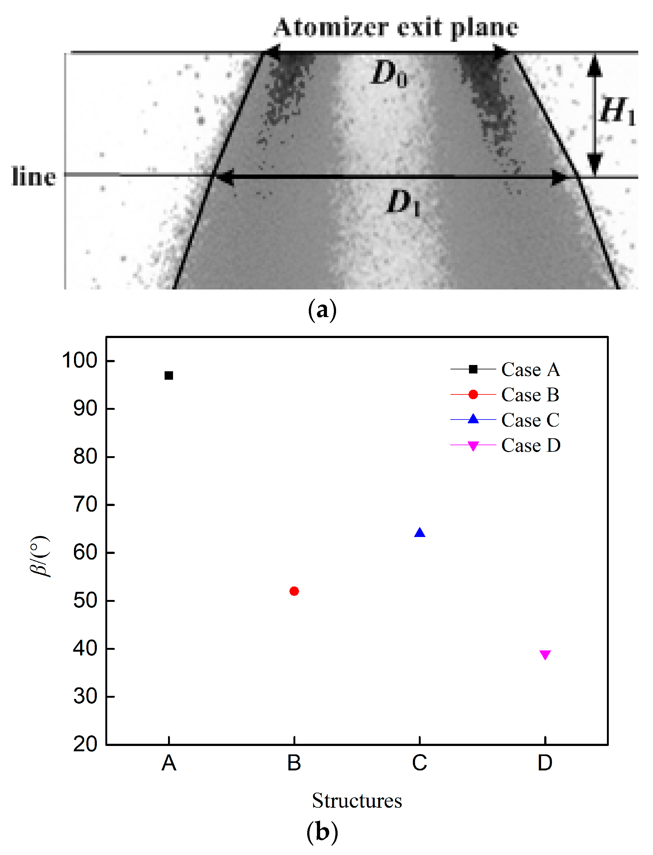
Figure 3, Figure 4 and Figure 5 show the flow fields, atomization fields, recirculation zones, and cone angles of the pressure-swirl atomizer and different air-blast atomizer structures under the same air inlet velocity (the ratio of the first-stage swirler area to the second-stage swirler area is 2:3). The experimental conditions are shown in Table 1, and the experiments are done under room temperature (10 °C). The asymmetries in the intensity plots are mainly induced by the centrifugal fan and the attenuation of the laser at the atomization field. The schematic of the jet angle is shown in Figure 3 (Case A). The jet angle is defined by the streamlines, and the maximum jet velocity is at the jet angle. The schematic diagram of the cone angle is shown in Figure 5a. Cone angle is defined by the dispersion region, which is formed between the left and right borders of the mass distribution. The left/right border of the spray is determined by radial integration of the count of the LIF signal from the center line of the injector at an axial distance, with a range of 95%. The cone angle is defined between the atomizer exit plane and the horizontal line (H1 = 10 mm). Combing the pressure-swirl atomizer and Case A, it can be seen that swirl air has a great influence on the flow field and atomization field. The flow fields and atomization fields of different air-blast atomizer structures have great differences too. All of the flow fields have high-speed jets, whereas the angle and velocity of the jets have great differences. The jet angle of Case A > Case C > Case B and Case D. The jets of Case B and Case D are absolutely parallel to the axis. The jet velocity of Case C > Case D > Case B > Case A. The large jet angle of Case A induces the small jet velocity. The above shows that the venturi tube decreases the jet angle and increases the jet velocity, and the sleeve decreases the jet angle and jet velocity, especially the jet velocity. The recirculation zone of Case A is the biggest, and that of Case B and Case D are small, whereas there is no recirculation zone of Case C. The above shows that the venturi tube decreases the recirculation zone and the sleeve increases the circulation zone. As shown in Figure 5, the cone angle of Case A (97°) > Case C (64°) > Case B (52°) > Case D (39°). The above shows that the venturi tube decreases the cone angle, and the sleeve decreases the cone angle too.
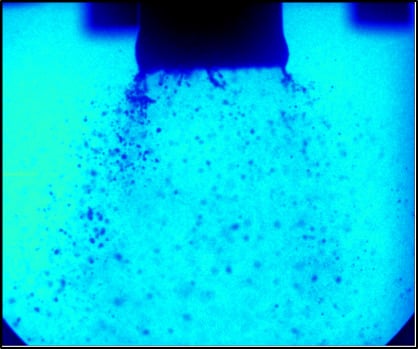
Figure 6 shows the liquid film breakup processes of pressure-swirl atomizer and different air-blast atomizer structures near the swirler exit under the same air inlet velocity (the ratio of the first-stage swirler area to the second-stage swirler area is 2:3). The experimental conditions are shown in Table 2. The fuel mass rate is 4.5 kg/h, and the experiments are done under room temperature (10 °C). The atomization of Case A is very good, and the liquid droplet is too small for the camera to capture. The liquid film breakup processes of the pressure-swirl atomizer and different air-blast atomizer structures have great differences. It can be seen that there is a longer liquid film near the pressure-swirl atomizer exit than air-blast atomizers. The reason is that the swirl air accelerates the breakup of liquid film. A liquid film is formed when there is a venturi tube (Case B), whereas the breakup performance is bad as there are a lot of big droplets at the downstream. The liquid film of Case B breaks into ligaments near the venturi tube exit, and the ligaments break into droplets due to the shear force. The breakup performance of Case C is better than that of Case B as there is no big droplet, which is induced by the strong sheer force of the two-stage counter rotating air. The film of Case C breaks into small droplets directly at the swirler exit. The breakup performance becomes worse when there is a sleeve (Case D) as there are ligaments and big droplets at the downstream. We can also see that there are small droplets in the central area of Case D, which illustrates that not all of the fuel impacts the sleeve wall to form the liquid film. Most of the fuel breaks into small droplets near the venturi tube exit of Case D, following the air into the main combustion area directly. The ligaments break into big droplets at the downstream area, due to the sheer force and surface tension. The ligaments and big droplets are harmful to the combustion process. The above shows that the venturi tube should be used with a two-stage counter rotating swirler with no sleeve for better atomization performance, and a third-stage swirler may need to be used if there is a sleeve, which will be studied in the future. Comparing Figure 3 and Figure 6, the big droplets induced the small velocity.
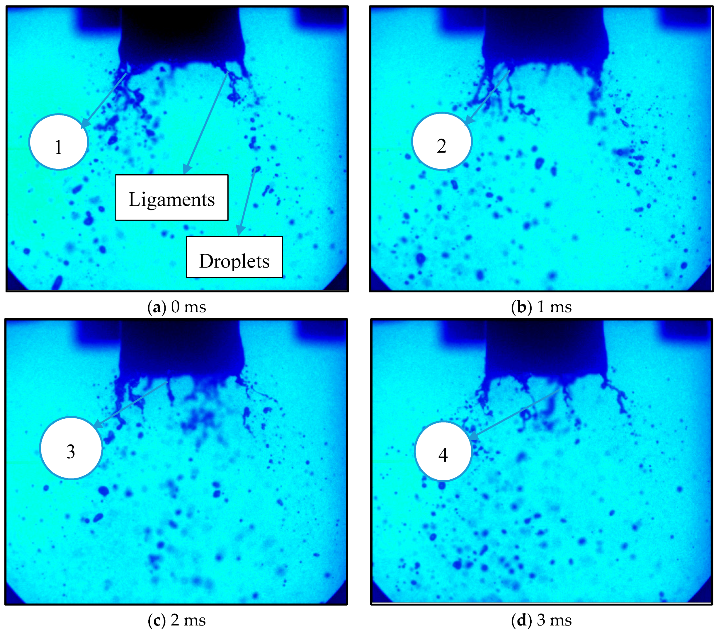
Figure 7 shows the liquid film breakup process of Case B near the swirler exit when the air mass rate is 18 kg/h and the fuel mass rate is 4.5 kg/h. As shown in Figure 7, the liquid film is rotating at the exit of the venturi tube due to the tangential velocity of fuel and air. The rotating liquid film breaks into a lot of rotating ligaments (1, 2, 3, 4) near the exit of the venturi tube, which is mainly induced by the centrifugal force and surface tension. The rotating ligaments break into big droplets at the downstream area.
3.2. The Influence of Fuel Temperature on Flow Field and Atomization Field
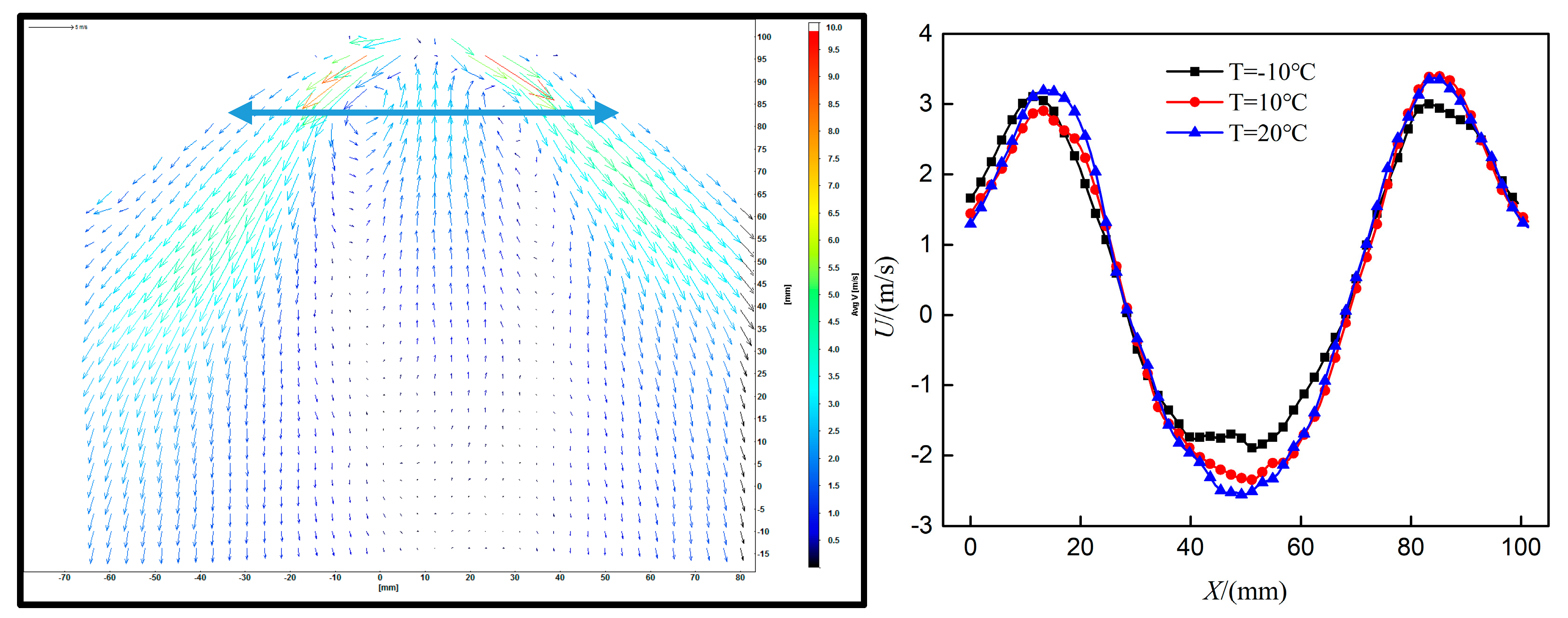
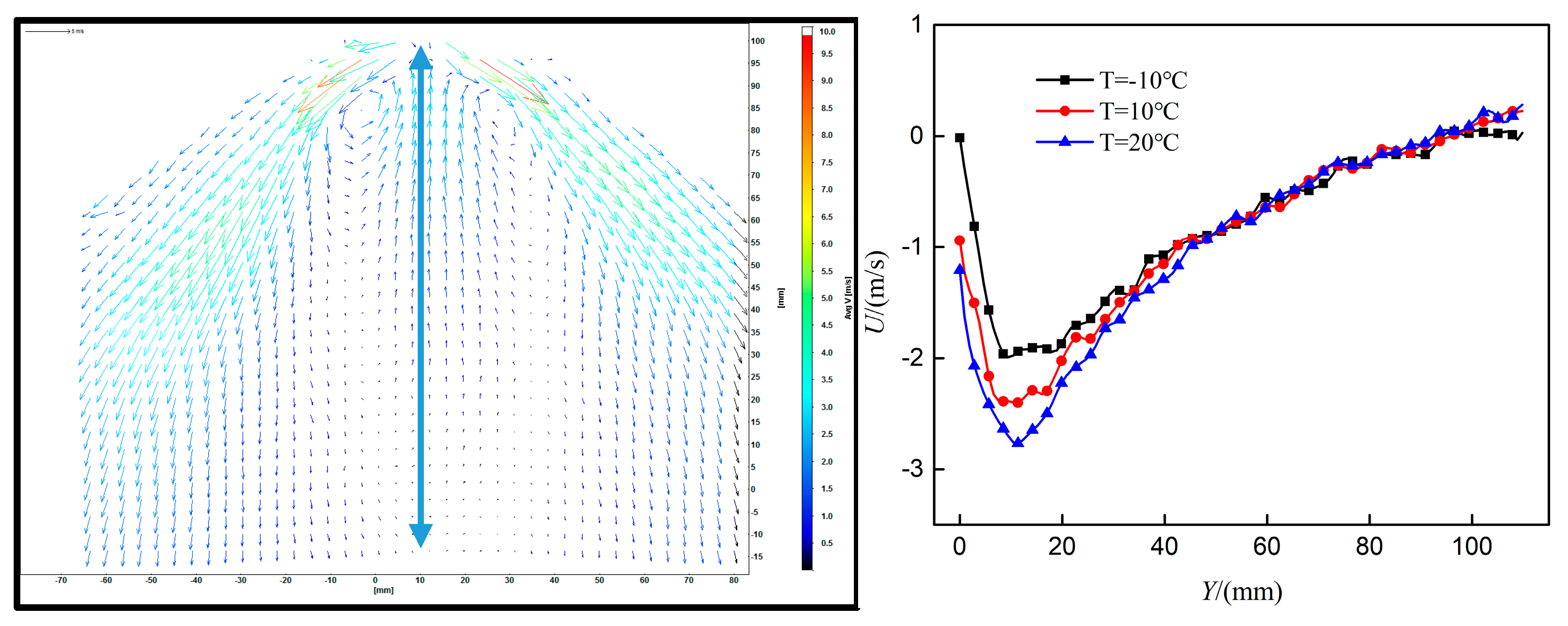
Figure 8 and Figure 9 show the influence of fuel temperature on the axial velocity of Case A, and the experimental conditions are shown in Table 3. The air mass flow rate is 18 kg/h, and the fuel mass rate is 2.4 kg/h. Fuel temperatures are within −10 °C and 20 °C. The arrow indicates the analysis area. Comparing Figure 8 and Figure 9, the fuel temperature mainly affects the axial velocity at the position near the axis and swirler exit of Case A. The maximum reversal flow velocity climbs with the increase of fuel temperature, which is mainly induced by the better atomization as the surface tension coefficient becomes smaller with the increase of fuel temperature. In addition, we can see that the length of the recirculation zone is nearly a constant value under different fuel temperatures, as shown in Figure 9.
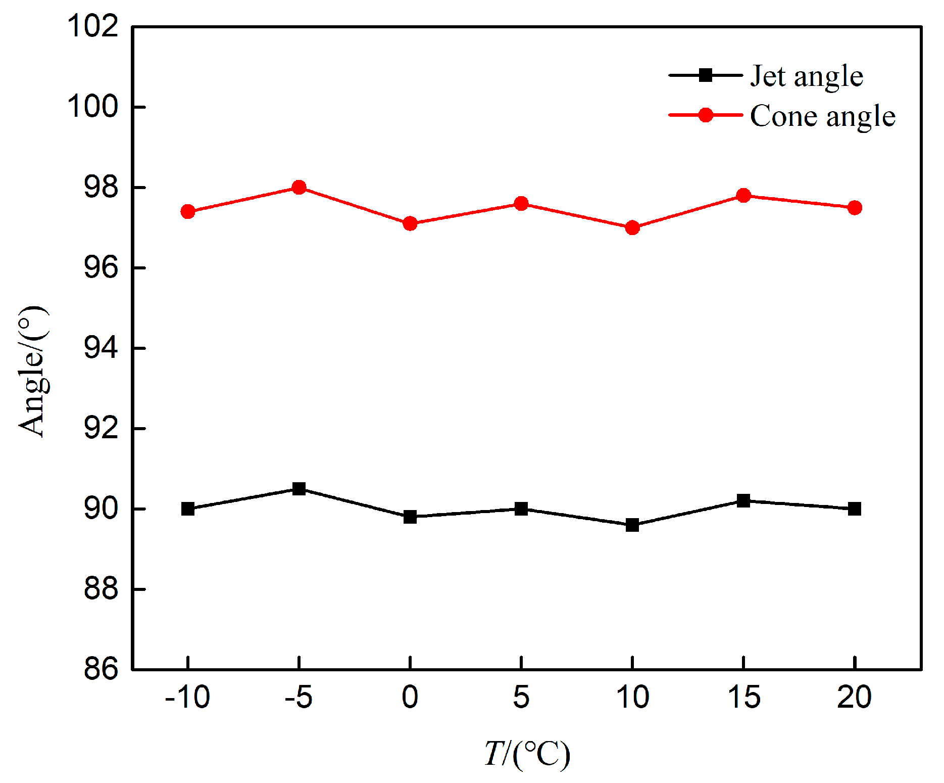
Figure 10 shows the jet angles and cone angles of different fuel temperatures using Case A, and the experimental conditions are shown in Table 3. The jet angles or cone angles are nearly a constant value under different fuel temperatures, which illustrates that the fuel temperature seldom has an effect on the jet angle and cone angle.
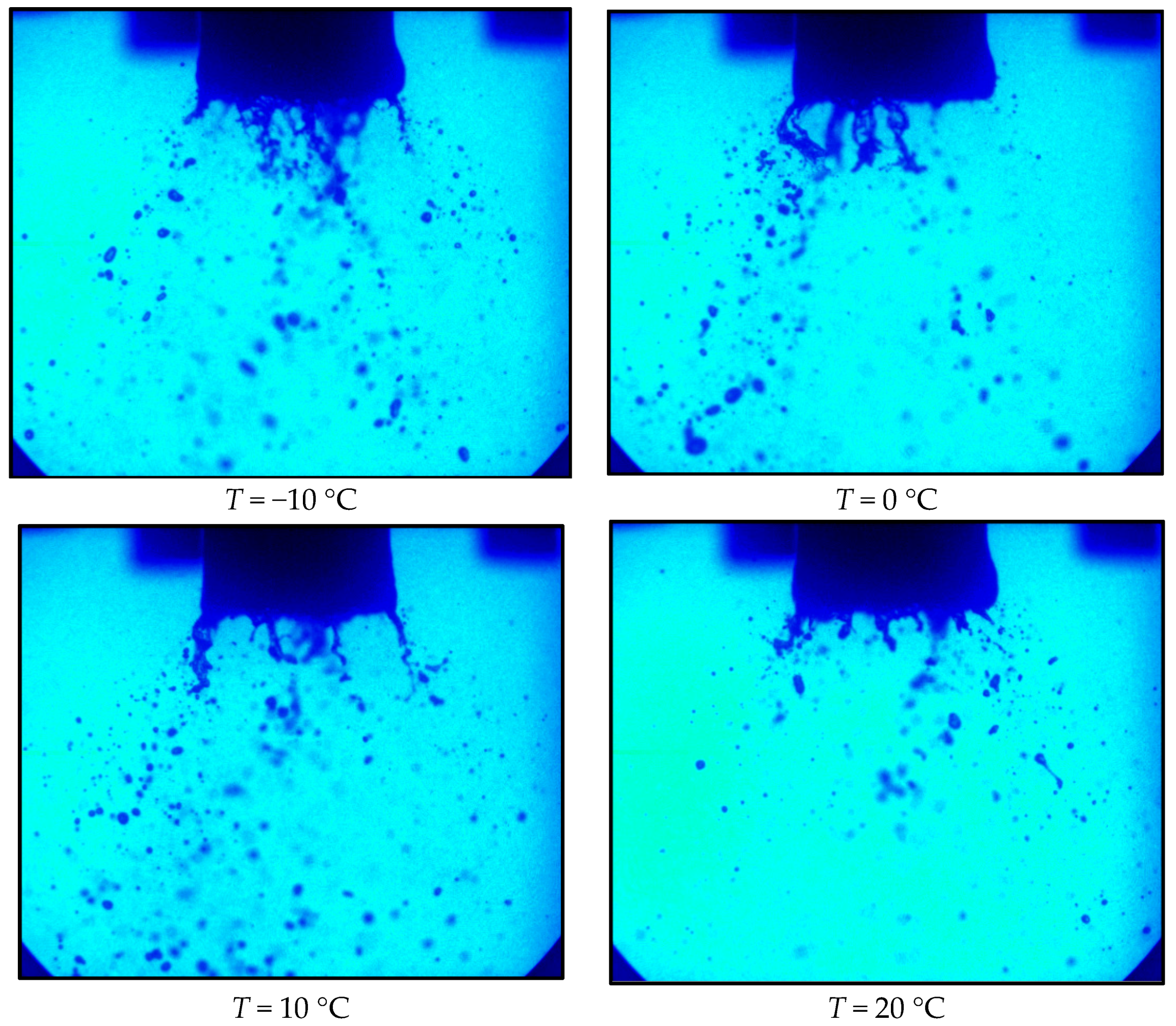
Figure 11 shows the liquid film breakup processes near the swirler exit of different fuel temperatures using Case B, and the experimental conditions are shown in Table 4. The length of ligaments and number of big droplets decrease with the increase of fuel temperature, especially when the fuel temperature is 20 °C, which is mainly induced by the surface tension as the surface tension coefficient becomes smaller with the increase of fuel temperature.
3.3. The Influence of Air Mass Rate on Flow Field and Atomization Field
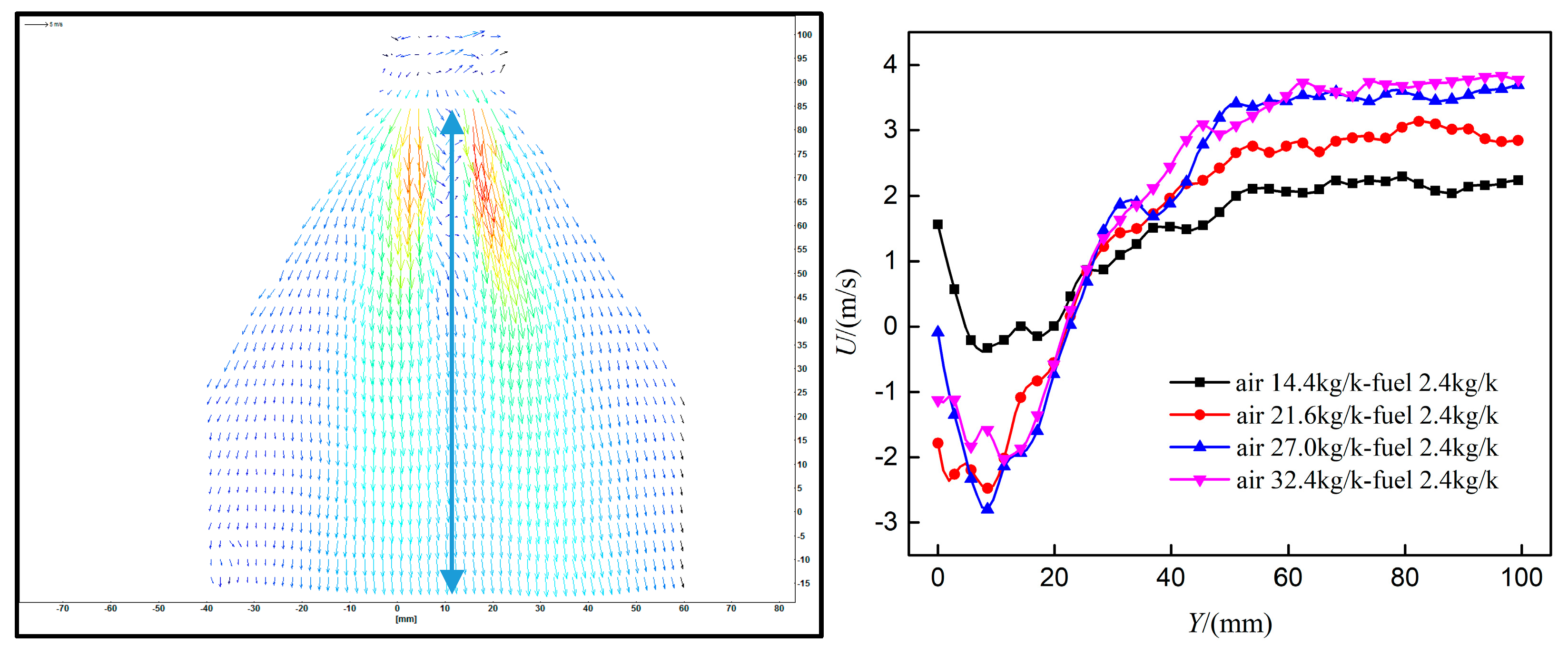
Figure 12 and Figure 13 show the influence of air mass rate on the flow field of Case B. The arrow indicates the analysis area. The flow field structures under different air mass rates are the exact same, in which there are a high-speed jet and a small recirculation zone. Swirler structure plays a major role in the form of the flow field structure. All of the jet angles are absolutely parallel to the axis, whereas the jet velocity climbs with the increase of air mass rate, as shown in Figure 12. As shown in Figure 12 and Figure 13, the axial velocity climbs with the increase of air mass rate, due to the larger air momentum and better atomization (smaller droplets).
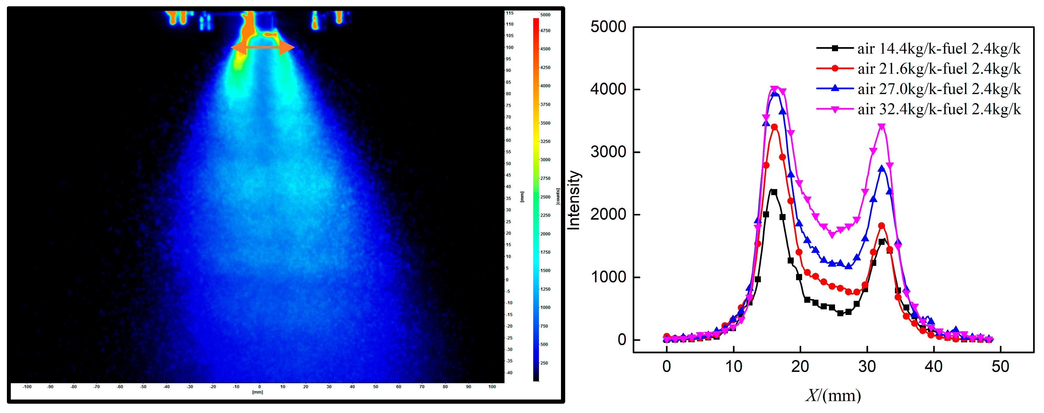
Figure 14 and Figure 15 show the influence of air mass rate on the atomization field of Case B. The arrow indicates the analysis area. The atomization structures under different air mass rates are completely the same, whereas the intensity of fluorescence signal climbs with the increase of air mass rate, especially near the axis. The above shows that the atomization performance becomes better (litter droplets) with the increase of air mass rate as the intensity of fluorescence signal is proportional to the fuel surface area when the laser intensity is a constant value, which can also be found in Figure 16.
Figure 16 shows the influence of air mass rate on the liquid film breakup process of Case B near the swirler exit. The ligaments become shorter and droplets become smaller with the increase of air mass rate, which means the air mass rate plays a major role in the atomization performance. A good atomization performance is important to the ignition and combustion.
3.4. The Influence of Fuel Mass Rate on Flow Field and Atomization Field
Figure 17 and Figure 18 show the influence of fuel mass rate on the flow field of Case B. The analysis areas of Figure 17 and Figure 18 are the same with those of Figure 12 and Figure 13. The flow field structures under different fuel mass rates are absolutely the same, in which there is a high-speed jet and a small recirculation zone. The jet velocity decreases with the increase of fuel mass rate. As shown in Figure 17 and Figure 18, there is a small reduction of the axial velocity with the increase of fuel mass rate, which is mainly induced by the worse atomization (larger droplets).
Figure 19 and Figure 20 show the influence of fuel mass rate on the atomization field of Case B. The analysis areas of Figure 19 and Figure 20 are the same as those of Figure 14 and Figure 15. The atomization structures under different fuel mass rates are completely the same. The intensity of fluorescence signal climbs slowly with the increase of fuel mass rate. The reason is that there are more big droplets with the increase of fuel mass rate, and the intensity of the fluorescence signal is proportional to the fuel surface area when the laser intensity is a constant value.
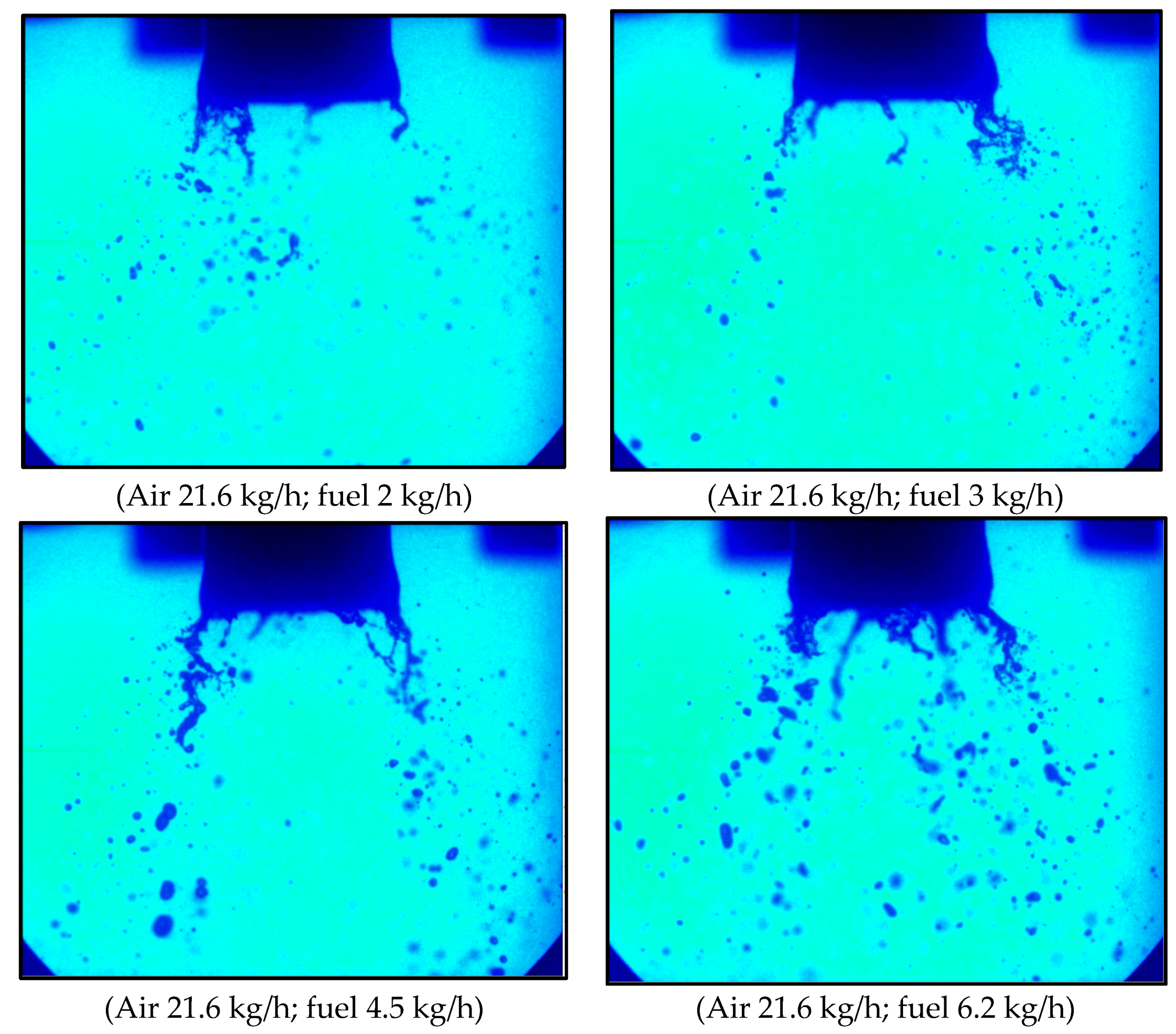
Figure 21 shows the influence of fuel mass rate on the liquid film breakup process of Case B near the swirler exit. The number of ligaments, the length of ligaments, and the number of big droplets climb with the increase of fuel mass rate, which is harmful to the ignition and combustion.
4. Conclusions
Flow field, atomization field characteristics, and liquid film breakup behaviors of a pre-filming air-blast atomizer were investigated using PIV, PLIF, and a high-speed shadowgraph technique under different air mass rates (ma), fuel mass rates (mf), and fuel temperatures (T). The influence of structures constituting the pre-filming air-blast atomizer on the flow field organization and atomization field organization were investigated too. The results show:
- (1)
- Air-blast atomizer structures have a great difference on the flow fields and atomization fields. The venturi tube decreases the jet angle and increases the jet velocity, and the sleeve decreases the jet angle and jet velocity, especially the jet velocity. The venturi tube decreases the recirculation zone and the sleeve increases the circulation zone. The venturi tube decreases the cone angle, and the sleeve decreases the cone angle too;
- (2)
- Air-blast atomizer structures have great differences on the liquid film breakup processes. The breakup performance of Case C is better than that of Case B as there are no big droplets at the downstream, which is induced by the strong shear force of two-stage counter-rotating air. The breakup performance becomes worse when there is a sleeve, which maybe should be used in a third-stage swirler;
- (3)
- The liquid film rotates at the exit of the venturi tube, due to the tangential velocity of fuel and air, and the rotating liquid film breaks into rotating ligaments and big droplets, due to the centrifugal force, surface tension, and shear force;
- (4)
- The fuel temperature mainly effects the axial velocity at the position near the axis and swirler exit, and the maximum reflux velocity climbs with the increase of fuel temperature, which is mainly induced by the better atomization;
- (5)
- Flow field structure and atomization structure are mainly determined by the swirler structure, whereas there are seldom influences of air mass rate and fuel mass rate on them.
The results of the mechanisms of flow field organization and atomization field organization in this study can be used to support the design of a new low-emission combustor. We will further study the influence of structure diameters on the flow field and atomization field to deepen understanding. In addition, the influences of flow field and atomization field on combustion are necessary to study.
Author Contributions
Experiments are done by X.F., C.L. and Y.M.; K.W. and Y.W. support the analysis of experiment results. G.X. gives suggestions on the design of the test rig. The paper is written by X.F., and corrected by C.L. and Y.M.
Funding
This research was funded by National Natural Science Foundation of China, grant number 51806219. And the APC was funded by 51806219.
Acknowledgments
This work was supported by the Project 51806219 of National Natural Science Foundation of China.
Conflicts of Interest
There is no conflicts of interest.
Nomenclature
| PIV | Particle Imaging Velocimetry |
| PLIF | Fuel Planar Laser Induced Fluorescence |
| mf | Fuel Mass rate, (kg/h) |
| ma | Air Mass rate, (kg/h) |
| T | Fuel temperature, (°C) |
| U | Axial velocity, (m/s) |
| β | Cone angle, (°) |
References
- Lefebvre, A.H.; Ballal, D.R. Gas Turbine Combustion: Alternative Fuels and Emissions. J. Eng. Gas Turbines Power 2010, 132, 77. [Google Scholar] [CrossRef]
- Dunn-Rankin, D. Lean Combustion: Technology and Control; Academic Press: Cambridge, MA, USA, 2013. [Google Scholar]
- Lefebvre, A.H.; McDonell, V.G. Atomization and Sprays, 2nd ed.; CRC Press: Boca Raton, FL, USA, 2017. [Google Scholar]
- Lefebvre, A.H.; Ballal, D.R. Gas Turbine Combustion; CRC Press: Boca Raton, FL, USA, 2010. [Google Scholar]
- Wang, H.; McDonell, V.; Samuelsen, S. Influence of Hardware Design on the Flow Field Structures and the Patterns of Droplet Dispersion: Part I—Mean Quantities. J. Eng. Gas Turbines Power 1995, 117, 282–289. [Google Scholar] [CrossRef]
- Ateshkadi, A.; McDonell, V.; Samuelsen, G. Effect of Mixer Geometry on Fuel Spray Distribution, Emissions and Stability. In Proceedings of the AIAA Aerospace Sciences Meeting and Exhibit, Reno, NV, USA, 12–15 January 1998. [Google Scholar]
- Wang, H.; McDonell, V.; Sowa, W.A.; Samuelsen, G.S. Scaling of the Two-Phase Flow Downstream of a Gas Turbine Combustor Swirl Cup: Part I and mdash; Mean Quantities. J. Eng. Gas Turbines Power 1992, 115, V003T06A031. [Google Scholar]
- Wang, H.; McDonell, V.; Samuelsen, G. The Influence of Spray Angle on the Continuous-and Discrete-Phase Flowfield Downstream of an Engine Combustor Swirl Cup. In Proceedings of the 28th Joint Propulsion Conference and Exhibit, Nashville, TN, USA, 6–8 July 1992. [Google Scholar]
- Mongia, H.; Gore, J.; Grinstein, F.; Gutmark, E.; Jeng, S.M.; McDonell, V.; Menon, S.; Samuelsen, G.; Santavicca, D.; Santoro, R. Combustion Research Needs for Helping Development of Next-Generation Advanced Combustors. In Proceedings of the 37th Joint Propulsion Conference and Exhibit, Salt Lake City, UT, USA, 8–11 July 2001. [Google Scholar]
- Hadef, R.; Lenze, B. Effects of Co-and Counter-Swirl on the Droplet Characteristics in a Spray Flame. Chem. Eng. Process. Process Intensif. 2008, 47, 2209–2217. [Google Scholar] [CrossRef]
- Liu, C.; Liu, F.; Yang, J.; Mu, Y.; Hu, C.; Xu, G. Experimental Investigation of Spray and Combustion Performances of a Fuel-staged Low Emission Combustor Part I: Effects of Main Swirl Angle. In Proceedings of the ASME Turbo Expo 2016: Turbomachinery Technical Conference and Exposition, Seoul, Korea, 13–17 June 2016. [Google Scholar]
- Lasheras, J.C.; Villermaux, E.; Hopfinger, E.J. Break-up and Atomization of a Round Water Jet by a High-Speed Annular Air Jet. J. Fluid Mech. 1998, 357, 351–379. [Google Scholar] [CrossRef]
- Engelbert, C.; Hardalupas, Y.; Whitelaw, J.H. Breakup Phenomena in Coaxial Airblast Atomizers. Proc. Math. Phys. Sci. 1995, 451, 189–229. [Google Scholar] [CrossRef]
- Lin, S.P.; Reitz, R.D. Drop and Spray Formation from a Liquid Jet. Annu. Fluid Mech. 1998, 30, 85–105. [Google Scholar] [CrossRef]
- Zhao, H.; Liu, H.F.; Tian, X.S.; Xu, J.L.; Li, W.F.; Lin, K.F. Influence of Atomizer Exit Area Ratio on the Breakup Morphology of Coaxial Air and Round Water Jets. AIChE J. 2014, 60, 2335–2345. [Google Scholar] [CrossRef]
- Roudini, M.; Wozniak, G. Experimental Investigation of Spray Characteristics of Pre-filming Air-blast Atomizers. J. Appl. Fluid Mech. 2018, 11, 1455–1469. [Google Scholar] [CrossRef]
- Garai, A.; Pal, S.; Mondal, S.; Ghosh, S.; Sen, S.; Mukhopadhyay, A. Experimental Investigation of Spray Characteristics of Kerosene and Ethanol-Blended Kerosene Using a Gas Turbine Hybrid Atomizer. Sādhanā 2017, 42, 543–555. [Google Scholar]
- Ochowiak, M.; Matuszak, M.; Włodarczak, S.; Krupińska, A.; Markowska, M.; Gościniak, A.; Szulc, T. The Concept Design and Study of Twin-Fluid Effervescent Atomizer with Air Stone Aerator. Chem. Eng. Process. Process Intensif. 2018, 124, 24–28. [Google Scholar] [CrossRef]
Figure 1.
Schematic of (a) pressure-swirl atomizer and (b) air-blast atomizers.

Figure 2.
Schematic of the high-speed shadowgraph experiment system.

Figure 3.
Flow fields and atomization fields of different air-blast atomizer structures (Average results).
Figure 3.
Flow fields and atomization fields of different air-blast atomizer structures (Average results).
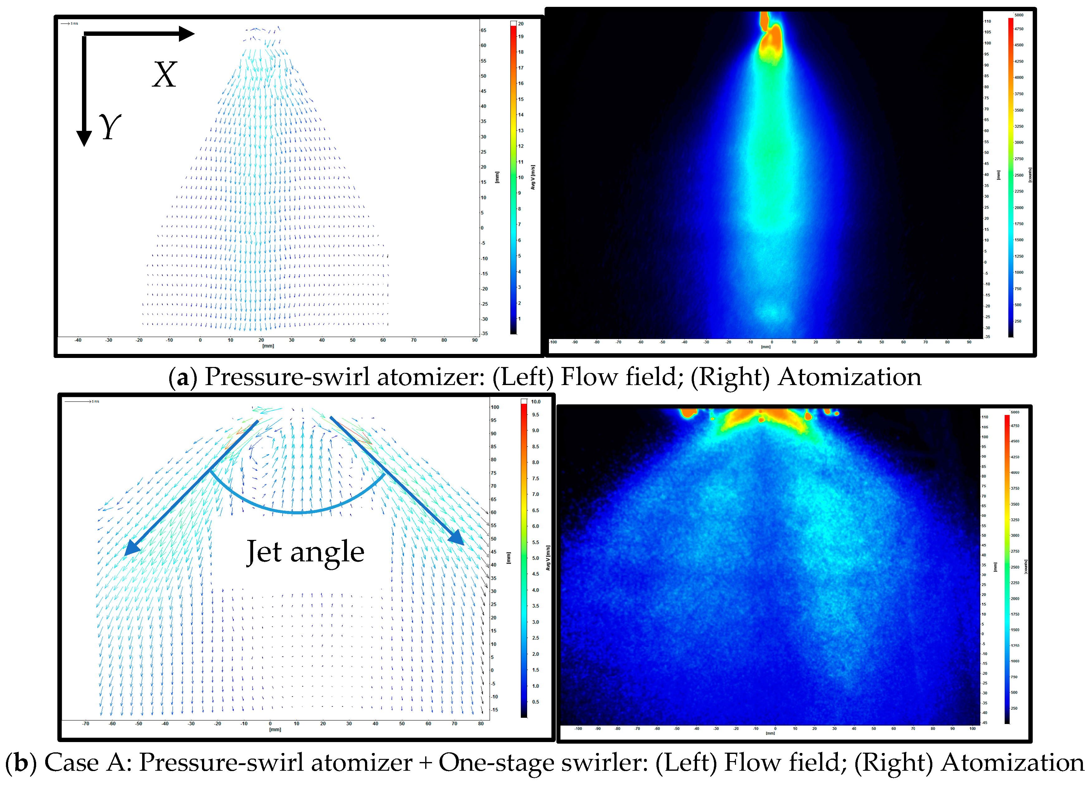

Figure 4.
Recirculation zones of different air-blast atomizer structures.

Figure 5.
(a) Schematic of cone angle and (b) cone angles of different air-blast atomizer structures.
Figure 5.
(a) Schematic of cone angle and (b) cone angles of different air-blast atomizer structures.

Figure 6.
Liquid film breakup processes of different air-blast atomizer structures (Transient results).
Figure 6.
Liquid film breakup processes of different air-blast atomizer structures (Transient results).
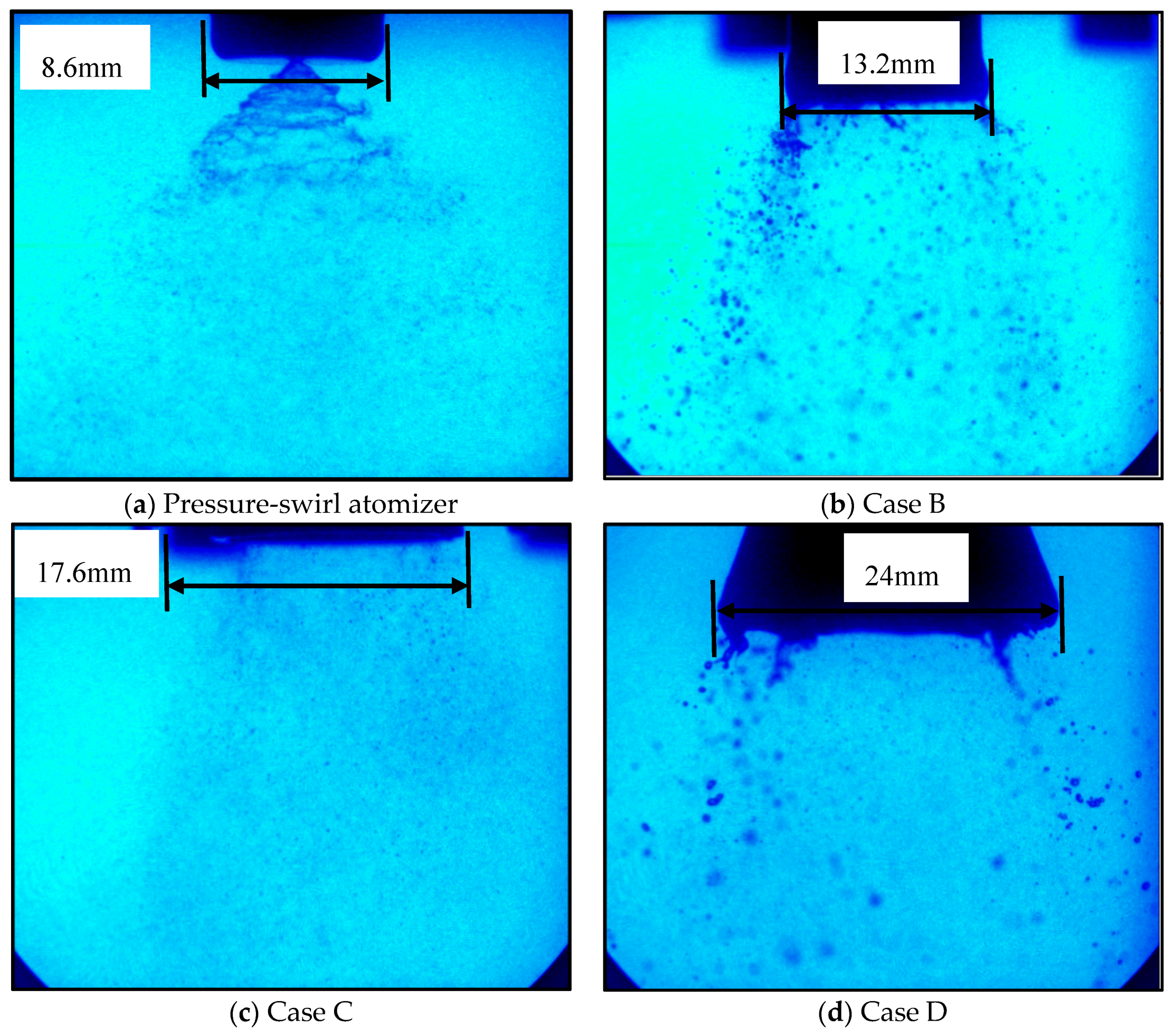
Figure 7.
Liquid film breakup process of Case B (Transient results).

Figure 8.
The influence of fuel temperature on the axial velocity (U) at a distance of 20 mm from the swirler exit in the y-direction (Case A).
Figure 8.
The influence of fuel temperature on the axial velocity (U) at a distance of 20 mm from the swirler exit in the y-direction (Case A).

Figure 9.
The influence of fuel temperature on the axial velocity (U) at the axis (Case A).

Figure 10.
Jet angles and cone angles of different fuel temperatures (Case A).

Figure 11.
Liquid film breakup processes of different fuel temperatures (Case B) (Transient results).
Figure 11.
Liquid film breakup processes of different fuel temperatures (Case B) (Transient results).

Figure 12.
The influence of air mass rate on the axial velocity (U) at a distance of 20 mm from the swirler exit in Y direction (Case B).
Figure 12.
The influence of air mass rate on the axial velocity (U) at a distance of 20 mm from the swirler exit in Y direction (Case B).
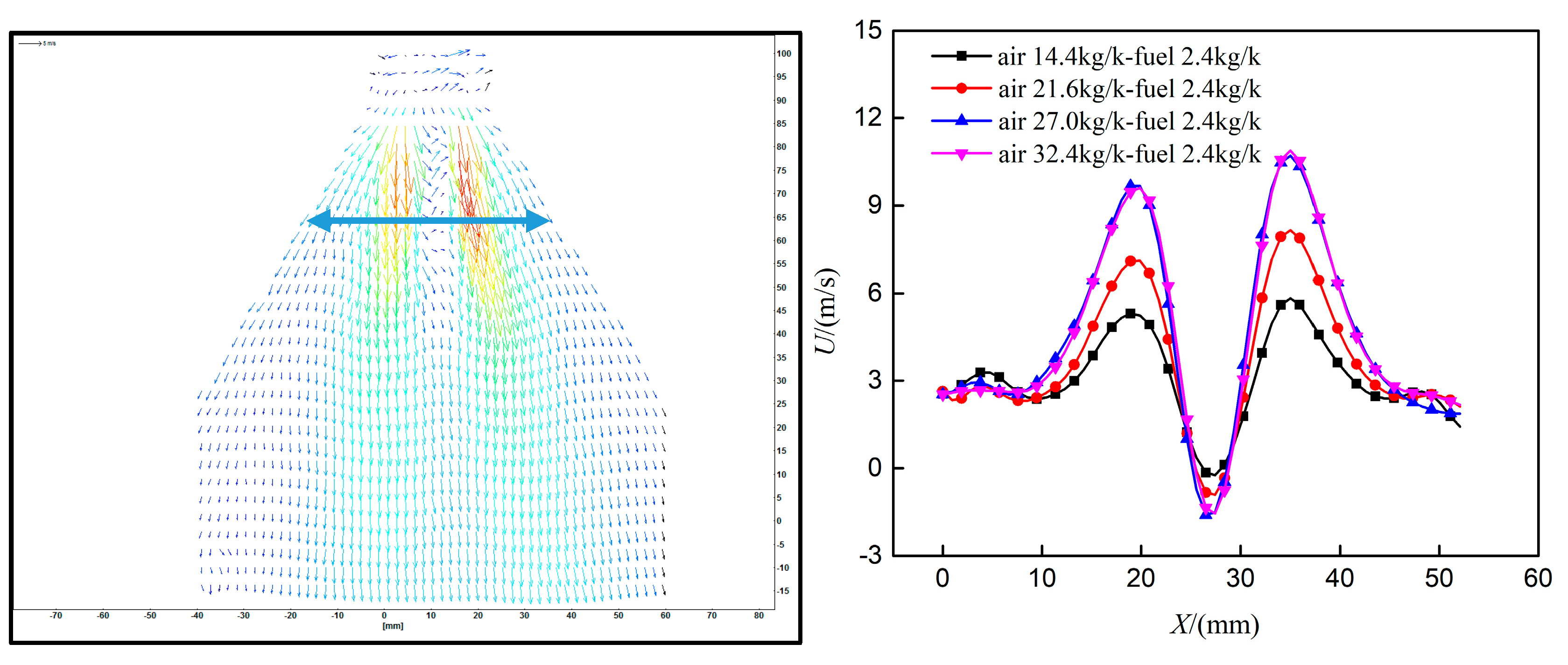
Figure 13.
The influence of air mass rate on the axial velocity (U) at the axis (Case B).

Figure 14.
The influence of air mass rate on fuel distribution at a distance of 5 mm from the swirler exit in the y-direction (Case B).
Figure 14.
The influence of air mass rate on fuel distribution at a distance of 5 mm from the swirler exit in the y-direction (Case B).

Figure 15.
The influence of air mass rate on fuel distribution at a distance of 15 mm from the swirler exit in the y-direction (Case B).
Figure 15.
The influence of air mass rate on fuel distribution at a distance of 15 mm from the swirler exit in the y-direction (Case B).

Figure 16.
The influence of air mass rate on liquid film breakup process (Case B) (Transient results).
Figure 16.
The influence of air mass rate on liquid film breakup process (Case B) (Transient results).

Figure 17.
The influence of fuel mass rate on the axial velocity (U) at a distance of 20 mm from the swirler exit in the y-direction (Case B).
Figure 17.
The influence of fuel mass rate on the axial velocity (U) at a distance of 20 mm from the swirler exit in the y-direction (Case B).

Figure 18.
The influence of fuel mass rate on the axial velocity (U) at the axis (Case B).
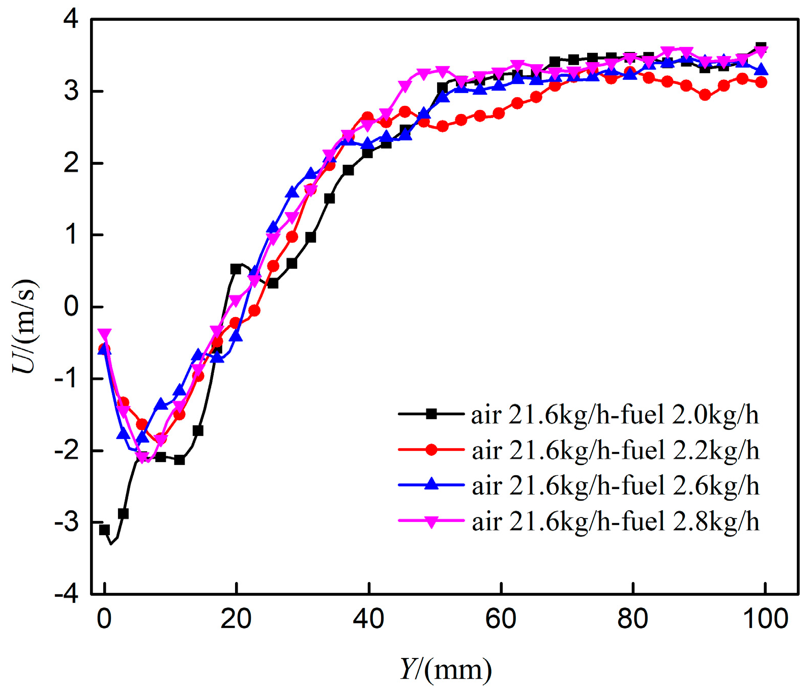
Figure 19.
The influence of fuel mass rate on fuel distribution at a distance of 5 mm from the swirler exit in the y-direction (Case B).
Figure 19.
The influence of fuel mass rate on fuel distribution at a distance of 5 mm from the swirler exit in the y-direction (Case B).
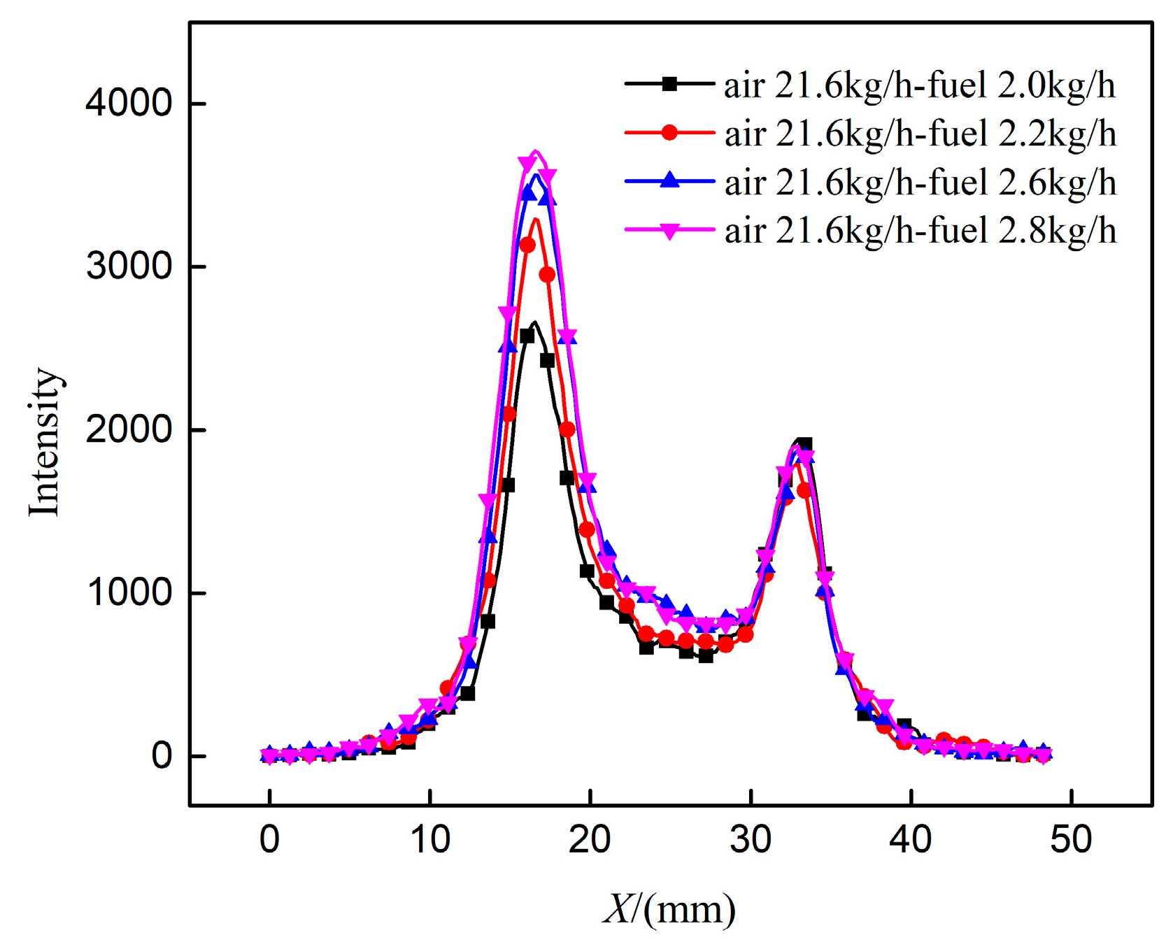
Figure 20.
The influence of fuel mass rate on fuel distribution at a distance of 15 mm from the swirler exit in the y-direction (Case B).
Figure 20.
The influence of fuel mass rate on fuel distribution at a distance of 15 mm from the swirler exit in the y-direction (Case B).

Figure 21.
The influence of fuel mass rate on the liquid film breakup process (Case B) (Transient results).
Figure 21.
The influence of fuel mass rate on the liquid film breakup process (Case B) (Transient results).

Table 1.
Experiment conditions.
| Case | ma/(kg/h) | mf/(kg/h) | T/(°C) |
|---|---|---|---|
| Atomizer | 0 | 2.4 | 10 |
| A | 21.6 | 2.4 | 10 |
| B | 21.6 | 2.4 | 10 |
| C | 54 | 2.4 | 10 |
| D | 54 | 2.4 | 10 |
Table 2.
Experiment conditions.
| Case | ma/(kg/h) | mf/(kg/h) | T/(°C) |
|---|---|---|---|
| Atomizer | 0 | 4.5 | 10 |
| B | 18 | 4.5 | 10 |
| C | 45 | 4.5 | 10 |
| D | 45 | 4.5 | 10 |
Table 3.
Experiment conditions.
| Case | ma/(kg/h) | mf/(kg/h) | T/(°C) |
|---|---|---|---|
| A | 18 | 2.4 | −10 |
| A | 18 | 2.4 | −5 |
| A | 18 | 2.4 | 0 |
| A | 18 | 2.4 | 5 |
| A | 18 | 2.4 | 10 |
| A | 18 | 2.4 | 15 |
| A | 18 | 2.4 | 20 |
Table 4.
Experiment conditions.
| Case | ma/(kg/h) | mf/(kg/h) | T/(°C) |
|---|---|---|---|
| B | 18 | 4.5 | −10 |
| B | 18 | 4.5 | 0 |
| B | 18 | 4.5 | 10 |
| B | 18 | 4.5 | 20 |
© 2019 by the authors. Licensee MDPI, Basel, Switzerland. This article is an open access article distributed under the terms and conditions of the Creative Commons Attribution (CC BY) license (http://creativecommons.org/licenses/by/4.0/).
Share and Cite
MDPI and ACS Style
Fan, X.; Liu, C.; Mu, Y.; Wang, K.; Wang, Y.; Xu, G. Experimental Investigations of Flow Field and Atomization Field Characteristics of Pre-Filming Air-Blast Atomizers. Energies 2019, 12, 2800. https://doi.org/10.3390/en12142800
AMA Style
Fan X, Liu C, Mu Y, Wang K, Wang Y, Xu G. Experimental Investigations of Flow Field and Atomization Field Characteristics of Pre-Filming Air-Blast Atomizers. Energies. 2019; 12(14):2800. https://doi.org/10.3390/en12142800
Chicago/Turabian StyleFan, Xiongjie, Cunxi Liu, Yong Mu, Kaixing Wang, Yulan Wang, and Gang Xu. 2019. "Experimental Investigations of Flow Field and Atomization Field Characteristics of Pre-Filming Air-Blast Atomizers" Energies 12, no. 14: 2800. https://doi.org/10.3390/en12142800
Note that from the first issue of 2016, this journal uses article numbers instead of page numbers. See further details here.