Study of Downhole Shock Loads for Ultra-Deep Well Perforation and Optimization Measures


1
College of Petroleum Engineering, China University of Petroleum-Beijing, 18 Fuxue Road, Changping, Beijing 102249, China
2
Department of Civil and Environmental Engineering, University of Pittsburgh, 3700 O’Hara St, Pittsburgh, PA 15261, USA
3
School of Petroleum Engineering, Chongqing University of Science & Technology, 20 East Road, University City, Shapingba District, Chongqing 401331, China
*
Authors to whom correspondence should be addressed.
Energies 2019, 12(14), 2743; https://doi.org/10.3390/en12142743
Submission received: 13 June 2019
/
Revised: 12 July 2019
/
Accepted: 15 July 2019
/
Published: 17 July 2019
(This article belongs to the Special Issue Development of Unconventional Reservoirs)
Abstract
:Ultra-deep well perforation is an important direction for the development of unconventional oil and gas resources, the security with shock loads is a difficult technical problem. Firstly, the theoretical analysis of perforated string is carried out, the dynamics models of which are established in the directions of axial, radial and circumferential. Secondly, the process of perforating with hundreds of bullets is simulated by using the software of LS-DYNA (ANSYS, Inc, Pennsylvania, USA). The propagation attenuation model of shock loads is established, and a calculation model to predict shock loads at different positions of the tubing interval has been fitted by considering multiple factors. The dynamic response of perforated string is studied, and the vulnerable parts of which are found out. Thirdly, the optimization measures are put forward for ultra-deep well perforation by the design of shock adsorption and safety distance of the packer. Finally, the field case of an ultra-deep well shows that the research method in this paper is practical, and the optimization measures are reasonable and effective. This study can provide important guidance to reduce shock damage and improve security for ultra-deep well perforation.
1. Introduction
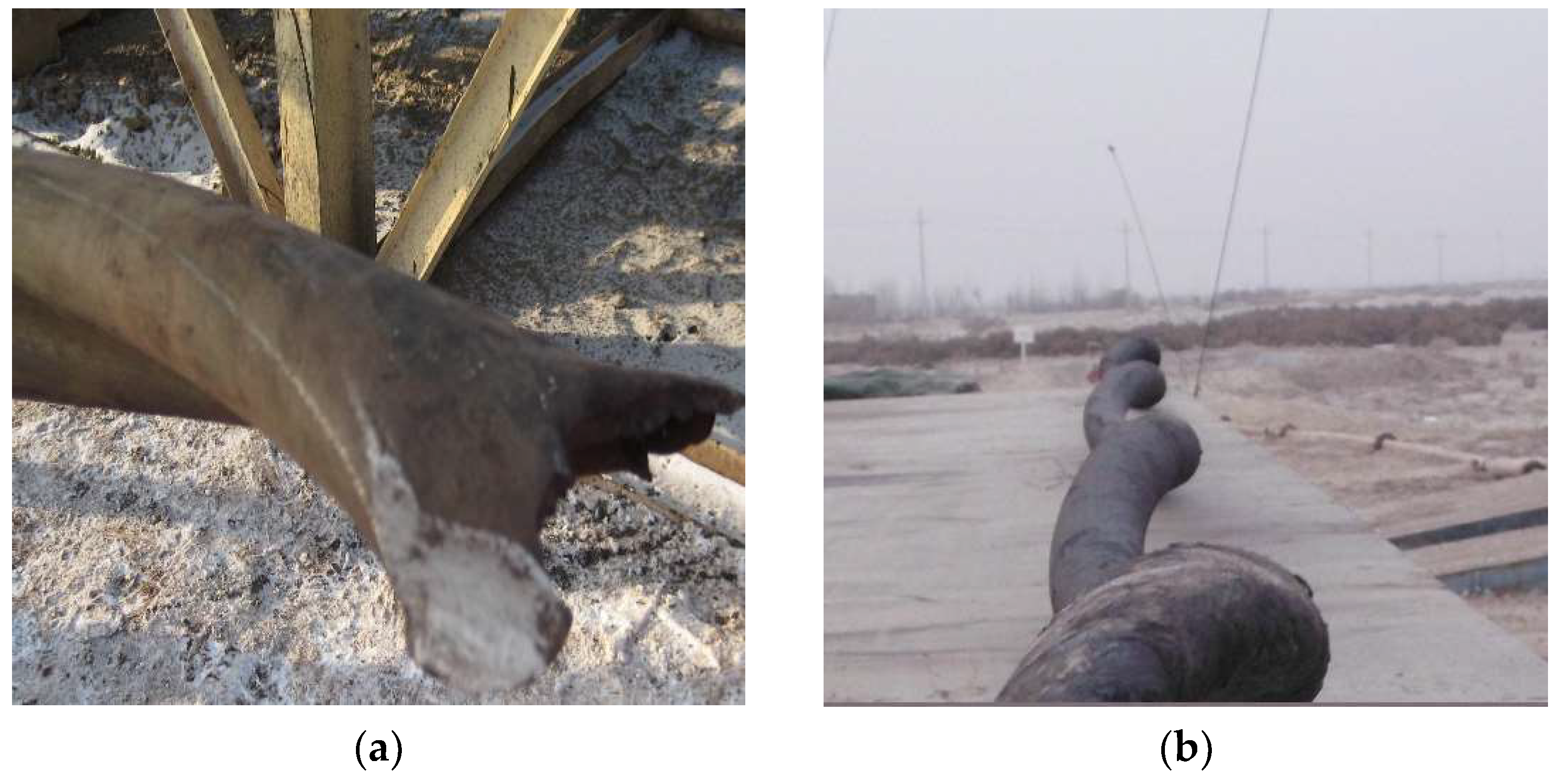
With the rapid development of petroleum exploration and development, unconventional oil and gas resources have become the focus of global oil fields, the field operation of which is getting harder and harder with the increase in deep and ultra-deep well exploitation [1]. Ultra-deep wells are characterized by deep reservoir burial, and a number of ultra-deep wells with depths of 8000 m have been drilled in China, the maximum formation pressure of which can be close to 140 MPa. With the ultra-high pressure conditions, the potential safety risk of perforation is getting higher, particularly in order to maximize well productivity and recoup the higher cost for ultra-deep wells, in recent years higher-shot densities, propellants, and larger perforating guns have become widely adopted and developed rapidly for field application. With the use of such systems comes the additional explosive load that could cause perforated string to burst, collapse, bend, buckle, and shear, as well as the packer seals to fail as perforating guns are detonated [2]. Figure 1 shows tubing damage (breaking and buckling) after field perforation of an ultra-deep well, resulting in the failure of perforation, and affecting the progress of oil testing operations with huge economic losses [3]. Predicting the magnitude and transient behavior of perforating shock loads is a critical step for ultra-deep well perforation that can avoid damage or destruction to tool strings and production equipment.
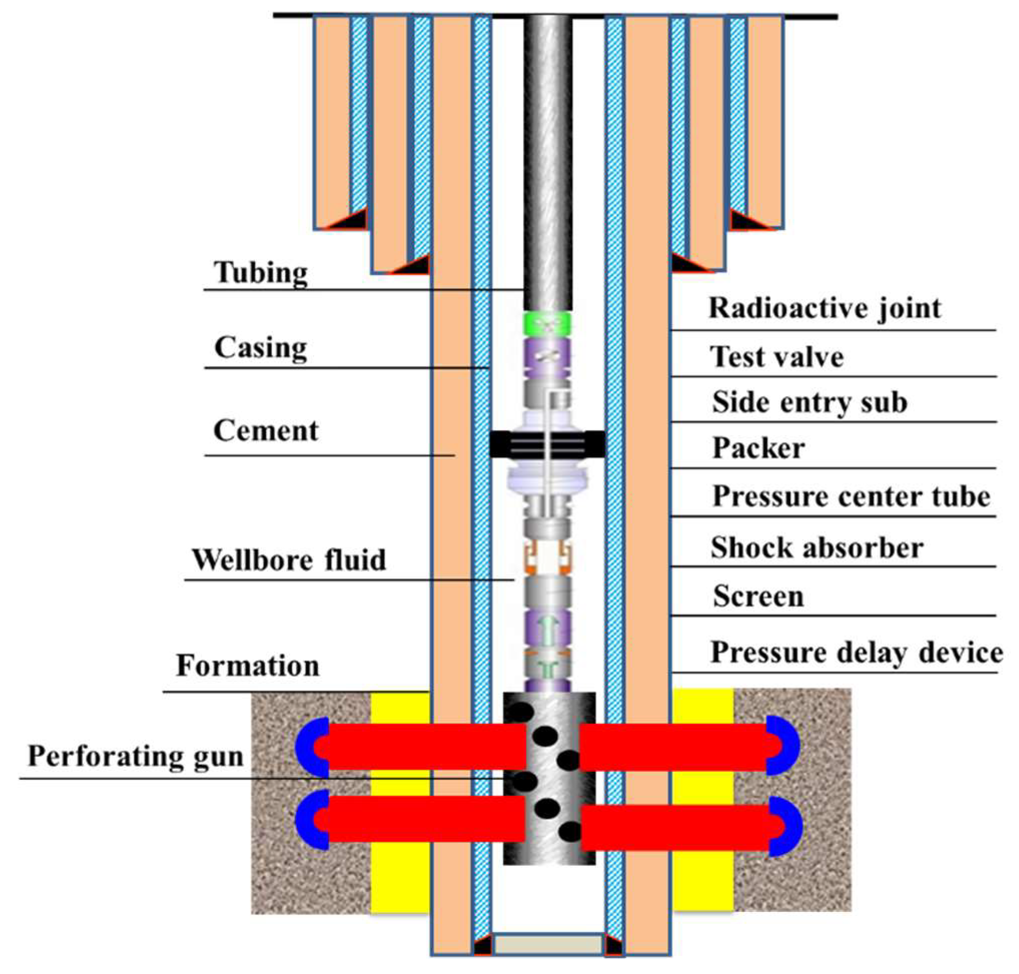
Due to the recent advances in well design and production techniques, tubing-conveyed perforating (TCP)-combined well testing is being increasingly used in challenging ultra-deep well completions [4]. A series connection of the perforating gun, tubing string, shock absorbers, packers, and other instruments is suspended into the downhole casing, as shown in Figure 2. When the shape charges detonate, the hollow carriers deform due to internal gas pressure and debris impacting the inner side of the carrier, the perforating jets puncture the hollow carrier wall, casing, cement, and formation. At the same time, a huge generated detonation wave will be released into the long and narrow space downhole with the packer setting. On the one hand, part of the shock loads will directly act on the perforating gun, which transfers to the tubing pipe, shock absorbers, packers, screen liner, the other connected components, resulting in a strong shock vibration of the perforated string system. On the other hand, the detonation gas inside the gun interacts with the wellbore fluid. The pressure difference between the gun and the wellbore produces shock waves in the wellbore fluid, propagating radially and axially up and down in a short time, leading to large fluid deformation and high-speed violent movement. The large-amplitude pressure waves that produce very large loads on the equipment, affecting the structural stability of the string system [5].
As there are potentially more perforation engineering problems in field operation, and the influence of perforating shock loads on the perforation safety attracted many researchers’ attention. At present, theoretical analysis, laboratory test, and numerical simulation are mainly used to study the shock damage during perforating.
Some scholars have carried out early relevant research. Lu et al. established the pressure pulsation equation under actual perforation conditions by using superposition fundamentals. However, only theoretical deduction and qualitative analysis are carried out due to the fact the equation is very complex [6]. The method of static theory analysis was used to study the perforated string by Yin et al., and it was concluded that that the high pressure formed in the sealing section during perforating is one of the reasons for the vibration of the string [7]. Yu et al. applied the finite clearance element theory method to study the contact problem of perforated strings in well testing, which is to use the finite element to discretize the string into several spatial straight beam elements along the axis, and the clearance elements are set on the nodes of the beam elements [8]. Through a field case of a complex well perforation project, the strength safety of perforated string has been theoretically studied by Dou et al., and the influence of perforation section length and downhole "pocket" length was obtained [9]. Xu et al. theoretically analyzed the influence of the shooting density and charge quantity on the strength security of perforated string by a field case of gas well completion [10]. According to the detonation theory, the peak pressure in the wellbore was obtained by calculating the energy of the detonation gas by Yang et al., and the strength of the string was analyzed based on the buckling theory [11]. Zhang et al. established the calculation model of perforating shock loads based on the theory of underwater explosion. The influence of the number of perforation bullets, detonation interval time, charge quantity, physical condition of artificial wellbore bottom, the depth of "pocket" on the perforating shock loads was analyzed [12].
In laboratory research, it’s hard to stimulate all of the real underground working conditions, and the cost for real tests is too high. Therefore, there are few studies in this field at present. Zhou et al. developed a comprehensive dynamic load test system, the acquired data of strain and outer ring pressure of perforated string were obtained in the perforation section [13]. A ground simulation test system was developed by Lu et al., in which the pressure and acceleration responses at the end of the perforated string were tested by experiments. A preliminary understanding of the dynamic response characteristics of perforated string with shock loads were obtained [14].
In the aspect of numerical simulation, many studies have emerged in this field in recent years. Chen et al carried out a mechanical analysis of the perforated string in ultra-deep wells by using the ANSYS/LS-DYNA finite element software. The results showed that the longer the operating string length is, the greater the perforation depth is, and the longer the distance from the restraint end is, the smaller the effective stress of the perforated string is, the more stable the whole downhole string system is, and some optimization methods for effectively alleviating the impact of perforated string are proposed [15]. The influencing factors of perforating shock loads in ultra-deep wells were studied by Chen et al., it was found that the axial force of perforated string was affected by factors such as "pocket" length, well fluid density, string length, perforation depth, well depth and perforating gun loading strategy [16]. Baumann et al. comprehensively summarized all influencing factors of perforation design, including the length of perforated interval, types, and sizes of perforated string, shaped charges, cable, and conveyance, rathole length, installation position of the packer, type and number of shock absorbers, wellbore and formation pressure with fluid properties [17]. The numerical simulation of the perforating process with a single perforation bullet was carried out by Teng, and the effects of shock loads on the perforated string were explored by static analysis [18]. Kang et al. studied the dynamic response of the perforating gun under different perforation conditions using the ANSYS/LS-DYNA software, whereby the influence of the axial and radial shock loads on the structural strength of the perforating was analyzed [19]. Cai et al. established a dynamic model of perforated string by using the method of space beam element and spring element with considering the annulus between tubing and casing, and the dynamic response process of which was simulated [20]. The perforated string was divided into space beam elements to simulate the dynamic response process by Yang, and the effects of the perforating shock loads, size and collapsing strength of perforated string, impact time on the maximum stress of the string for a horizontal well were studied [21]. Zhang et al. obtained the vibration displacement, velocity, acceleration and equivalent stress of perforated string by establishing a finite element model. The influence of the length and thickness of the string on the stress intensity was studied [22]. Li et al. reviewed that the shock vibration of the perforated string is caused by perforating bullets and bumper jar shock. The variation and distribution of shock pressure along the string with time were not clear [23]. Based on the AUTODYN software (ANSYS, Inc, Pennsylvania, USA), the variation law of density, velocity and pressure fluctuation of perforation fluid were analyzed by Li, and the effects of charge quantity and density on perforated string were studied [24]. Li et al. analyzed perforating pressure fluctuation of annular by software simulation based on field measured data, the vibration velocity and acceleration of perforated string were obtained. The results show that the stress concentration occurs near the packer, where the stress value is the largest [25]. The professional commercial software has been developed by some major oil companies (Schlumberger, Halliburton, etc.), which can simulate dynamic downhole conditions of ultra-deep wells and model all relevant aspects of well perforation, including gun loading, wellbore pressure waves and related fluid movement [26,27,28,29,30].
These studies set a foundation for further research on the shock damage of perforating shock loads. However, there is a lack of a model to accurately calculate the shock loads during perforating under different conditions, especially for the high formation pressure condition for ultra-deep wells. These numerical simulation studies are often aimed at a single perforating bullet, which is not consistent with the actual working conditions in the field with hundreds of bullets. Meanwhile, the vulnerable position of the perforated string needs to be found, and the propagation law of perforation shock load in the wellbore is not clear. In this paper, through theoretical and numerical simulation analysis, the effects of the downhole perforating shock loads on the perforated string system are analyzed for ultra-deep well, and the propagation law of perforating shock loads in the wellbore is explored. A model for predicting the magnitude of shock loads under different perforation conditions is established, the dynamic response process of the perforated string is studied, and the relevant optimization measures are put forward, including the design of shock absorption and safety distance of the packer. Finally, the research results are applied to the perforation of an ultra-deep well case.
2. Mechanical Model of a Perforated String
As the initial output unit of perforating shock loads, analyzing the dynamic response behavior of perforated string system is the basis of studying the shock damage for ultra-deep wells. The security of the perforated string and its correlative problems gradually turned into the investigative object for researchers in this field in recent years. In this study, the dynamics models of perforated string have been established in the directions of axial, radial and circumferential, the displacement of perforated string can be calculated by numerical integration method.
2.1. Axial, Radial and Circumferential Model of Perforated String
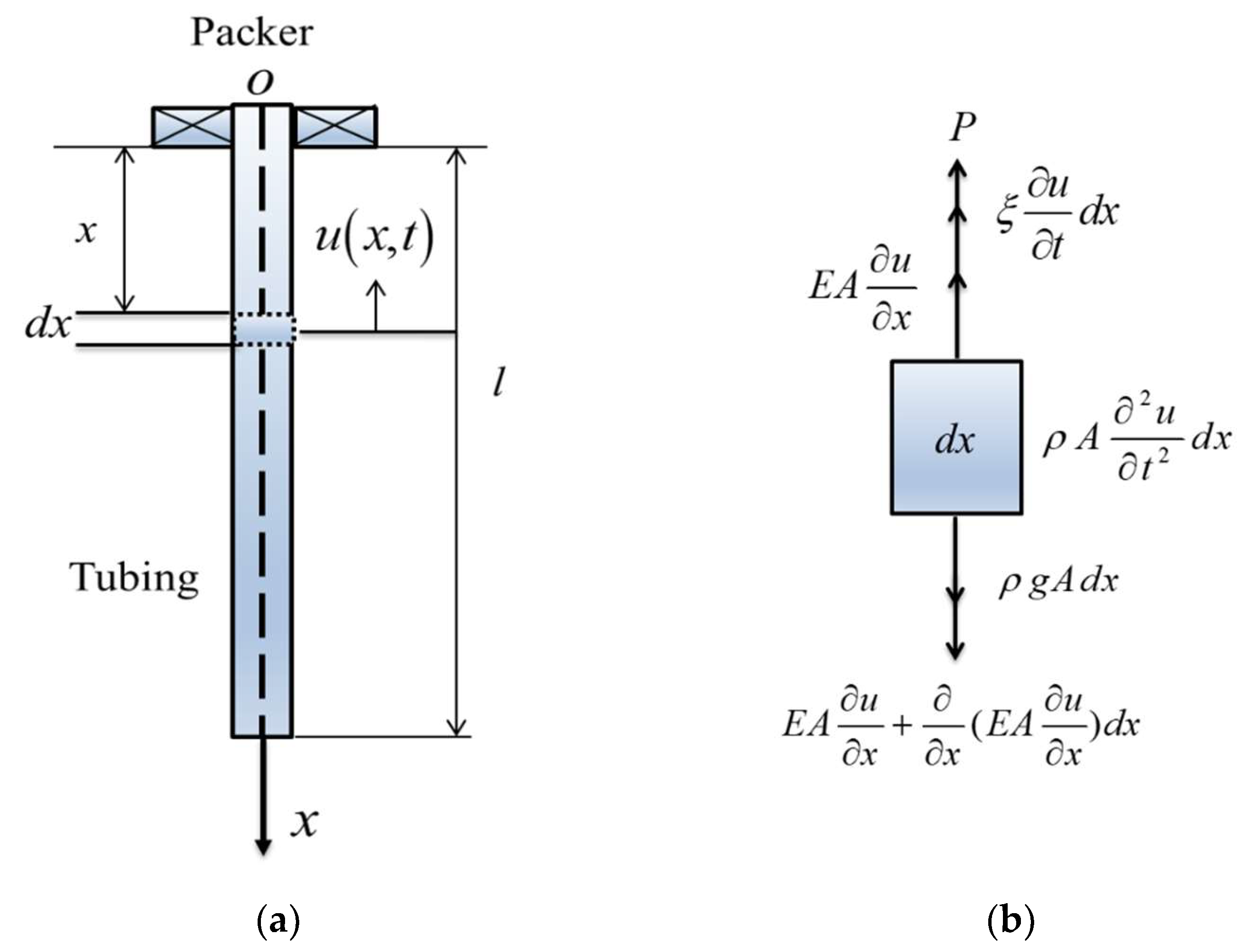
In the process of perforation operation, due to the asymmetry of the perforating charge structure, the spiral distribution pattern and the coupling effect of the sequential explosion, perforating shock loads on the string can be divided into in axial, radial and circumferential directions simultaneously. Taking the perforated string below the packer as the research object, which the string can be assumed to be a cantilever with one fixed end and the other end applied with shock loads. According to the structure of the perforation string system and the operation condition, the following assumptions are made by the authors: the material of the perforated string is an isotropic homogeneous continuous linear elastic body, satisfying Hooke’s law; the string is a continuous uniform-section straight thin rod and the effects of wellbore fluid and casing are ignored; the shock loads are all applied on the bottom of the string. A rectangular coordinate system is established with the center of packer as the origin, the down direction as the x positive direction and right direction as the y positive direction. The mechanical model of the perforated string can be described in Figure 3.
According to D’Alambert’s principle, Equation (1) can be written:
where is the density of the string, kg/m3; is the cross sectional area of the string, in m2; is the elasticity modulus, Pa; is the axial displacement of the string at time t and position x, in m; is the gravitational acceleration, m/s2; is the damping coefficient of the string in perforating fluid; is the perforating impact load, MPa.
Considering the effect of the gravitation, and assuming the external loads uniformly distribute along the string, the force acting on perforated string can be established in Equation (2):
where is the unit impulse function. By simplification, the differential equation of perforated string vibration under axial shock loads can be obtained in Equation (3):
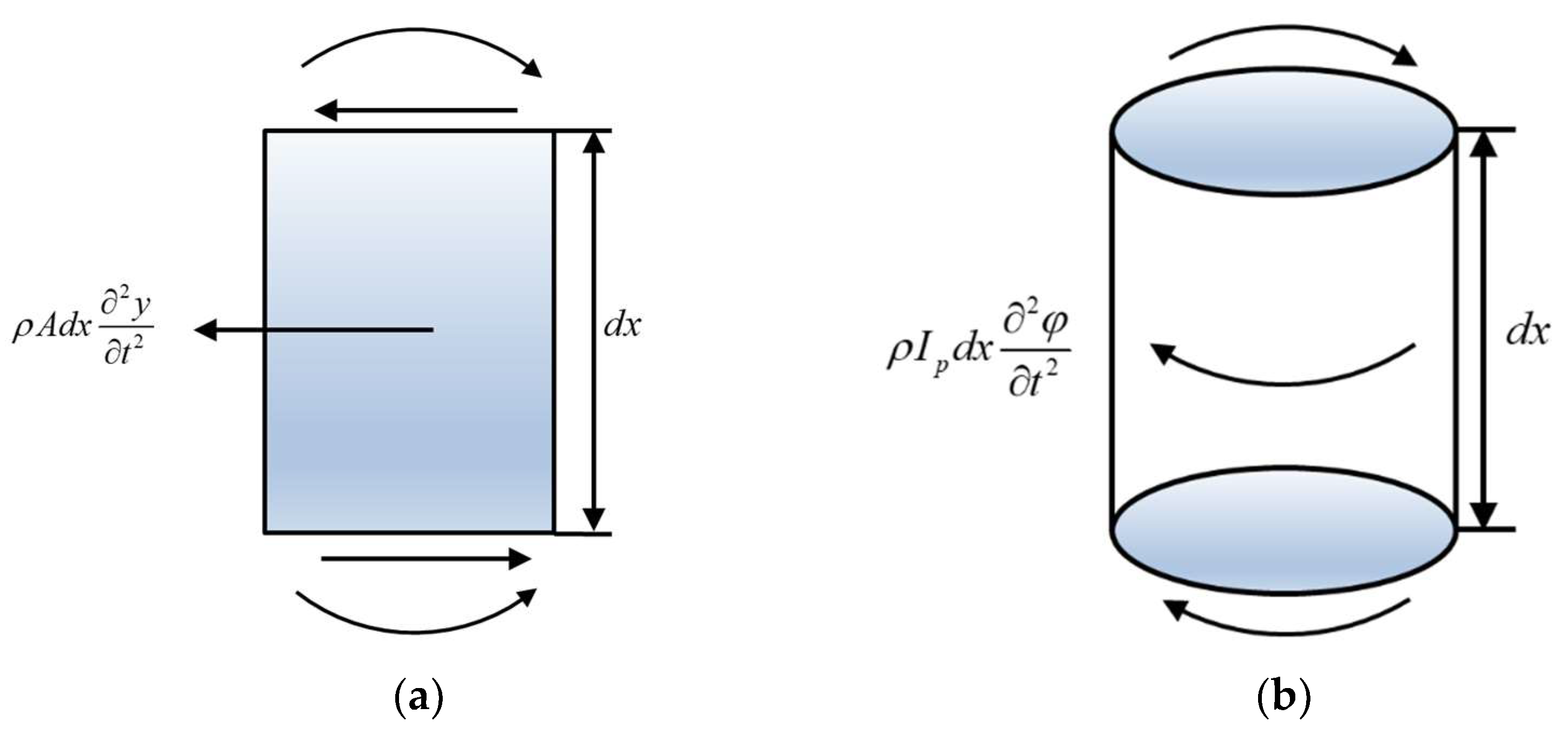
To build the dynamic model of perforated string under radial shock loads, the string is simplified as a cantilever with a fixed end and a free end, like the condition of axial shock loads. Following assumptions are made by authors: main inertia axes of cross sections of the string are in the same plane where the string moves radially; shock loads are applied on the lowest part of the string; bend is the main deformation of the string. Like the axial analysis of the perforated string, a unit of dx in the radial direction of the string is shown in Figure 4a. Similarly, the cross sections of the string are assumed to be planes with axial and circumferential vibrations. Like the coordinate system of the string under axial shock loads, the down direction along the string was assumed positive. A unit of the perforated string in the circumferential direction is shown in Figure 4b.
The radial vibration differential equation of the string can be established in Equation (4):
where the inertia moment of the perforating string, m4; is the radial displacement of the perforating string at position x , in m, and time t.
The circumferential vibration equation can be expressed by Equation (5):
2.2. Displacement of Perforated String
Due to the fixed restriction, the displacement of the perforated string is zero at the position of the packer. Meanwhile, the internal force on the end face of the string is also zero. Therefore, boundary conditions at the fixed end and the free end of the string can be demonstrated in Equation (6):
where is the angular displacement of the tubing at position x and time t, rad; G is the shear modulus, Pa; is the polar moment of inertia of a string cross section, m4.
Before the explosion of the perforation charge, the perforated string remains still and its initial velocity is zero. As the effect of gravity of the string on its displacement is ignored, the initial displacements of every string unit can be regarded as zero. The initial conditions can be obtained using Equation (7):
Based on the above boundary and initial conditions, the longitudinal free vibration equation of the perforated string can be established in Equation (8):
The solution process of the longitudinal free vibration equation of perforated string is shown in Appendix A. According to the solving process of the axial mechanical model, the infinite series of sinusoidal vibration modes can be used to express the displacement response of perforated string under axial shock loads, as shown in Equation (9):
Through the above theoretical analysis, the dynamic response of perforated string has been studied. However, it is difficult to make a comprehensive analysis for the complicated shock waves loading rules and the dynamic response laws of perforated strings through theoretical models, especially for the dynamic fluid-structure interaction. In the laboratory research field, it is difficult to fully stimulate the real downhole working conditions, especially for the complex underground environments found in ultra-deep wells. What’s more, the experimental data obtained is limited and the cost of obtaining it is too high. As for numerical simulations, if the modeling and meshing are reasonable, they can fully present the perforating explosion process and simulate various working conditions for ultra-deep wells, with a comprehensive analysis of the dynamic response of perforated string by considering the dynamic fluid-structure interaction. In this way, the perforating shock loads under different perforation conditions can be obtained, and the propagation laws of which in the wellbore can be studied. At last, the optimization design and proposal can be proposed, which can provide an important theoretical basis for field perforating operations.
3. Numerical Simulations
The process of bullet explosion, jet formation, and penetration during perforating have been simulated by researchers by combining the arbitrary Lagrange-Euler (ALE) method with the self-adaptive mesh technique (AMR) [31,32,33]. However, due to the complexity of modeling and meshing, a single perforating bullet or a few were simulated in these studies. In addition, the effects of high formation pressure for ultra-deep wells were not considered, the actual downhole perforation conditions cannot be presented accurately, affecting the results of numerical simulations. In this study, hundreds of perforating bullets have been simulated with considering the actual ultra-deep well perforation environment by using the large computers. The physical models are created by ANSYS/WORKBENCH, meshed by HYPERMESH, and ANSYS/LS-DYNA is adopted for numerical simulations. A number of numerical simulations are carried out with extracting calculation results of different perforating parameters and simulating various working conditions.
3.1. Modeling and Meshing
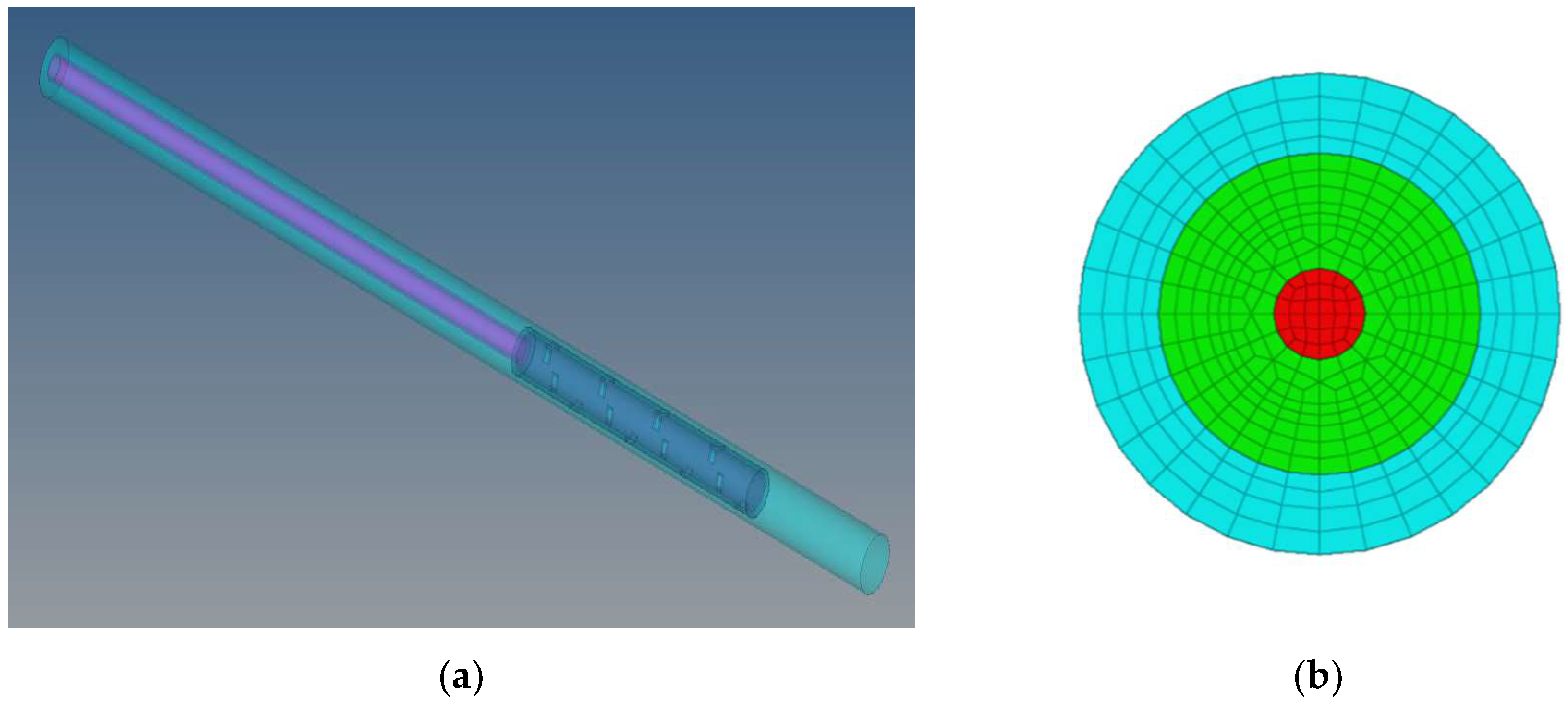
Due to the plastic deformation of the pipe string and the damage behaviors such as bending and fracture often occur below the packer, the tubing in a well section below which can be taken as a specific research object. In the actual perforation operation for ultra-deep wells, the length of the tubing varies from tens of meters to several hundred meters under different perforating conditions [34]. A 3D physical model can be established by simplification, which mainly consists of perforating gun, tubing and casing by ignoring the thread of each connector. The upper end of the tubing is radially restrained by the packer, the lower portion is restricted by the well bottom, and the surrounding is confined by the casing, as shown in Figure 5a. The perforating gun length is 9 m, tubing length is 20 m, rathole length is 4 m; the steel grade of the perforated string is N80, the size of the gun, tubing and casing are 177.80/152.53 mm, 73.02/62.00 mm, 244.40/220.50 mm, respectively. The yield limit of the casing is 460 MPa, and that of tubing is 536 MPa. The number of perforating bullets is 180, which are distributed in the perforating gun with a phase angle is 90°. The charge per hole is 45 g, the charge type is Royal Demolition Explosive (RDX). The remaining space inside the gun is filled with air, the tubing and annulus are filled with wellbore fluid, the density of which is 1.78 g/cm3. The formation pressure is 130 MPa, the wellbore initial pressure is 125 MPa. The time range is from 0 to 5000 μs.
Due to the highly nonlinear nature of the explosion, the grid of full hexahedron must be used in the fluid area and partially encrypted at the charge, as shown in Figure 5b. Each part of the material on the joined interface must have the common mesh node, which can effectively capture the movement and deformation of the construction of the material, and ensure energy between the partial grid effective transmit. The Lagrange algorithm is used in the perforating gun, tubing and casing. The Arbitrary Lagrange-Euler (ALE) algorithm is used in charge, air, and fluid, in which the space position of the ALE grid remains unchanged, and the material flows among the grids. The mean grid spacing is 4–5 mm and the total number of grids is about 1 million. The non-linear plastic kinematic hardening model (MAT_PLASTIC_KENEMATIC) is adopted for the material of the pipe string, as shown in Equation (10):
where is the yield stress; is the strain rate; and are the parameters of strain rate; is the initial yield stress; is the plastic hardening modulus; is the effective plastic strain.
The fluid is coupled to the solid interface and the material model of the charge is high-energy dynamite (High_Explosive_Burn), the state equation is EOS_JWL, as shown in Equation (11).
where is the relative volume; are the explosive physical parameters; is the initial internal energy of unit explosive volume.
The unit algorithm adopts the constant stress unit algorithm of SOLID164 unit. The parameters of the RDX explosive are shown in Table 1.
The final model can be imported to the LS-DYNA in the form of K file, which the model parameters are defined by keywords. *INCLUDE and * INCLUDE TRANSFORM can be used to import the meshed models, using *INITIAL_DETONATION to define the detonation point and initiation time, using *ALE_MULTI - MATERIAL_GROUP to define the material of fluid field grids which can flow in each other, using *CONTACT_ERODING_SURFACE_TO_SURFACE to define the erosive face to face contact algorithm, using the keyword *CONSTRAINED_LAGRANGE_IN_SOLID and *SECTION SOLID ALE to define the fluid-solid coupling, using *CONTROL_TERMINATION and *CONTROL_TIMESTEP to define the simulation time and the output step of the model calculation [35].
3.2. Computing Results
Based on the above modeling and parameters setting, numerical simulations are carried out on a large computer, with the data analysis by post-processing software of LS-PrePost (LSTC, California, USA). The unit during simulation is cm-g-μs, the pressure nephogram unit is 1011 Pa.
3.2.1. Perforating Dynamic Pressure
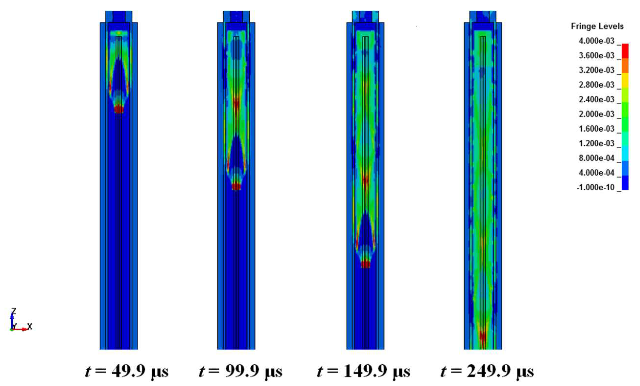
Figure 6 shows the pressure variation of perforation gun section after the perforating bullets detonate from t = 49.9 μs to t = 249.9 μs, and the pressure waves propagate from top to bottom along wellbore with the explosives explode gradually, which will reflect when reaching the bottom of the wellbore. The generated pressure waves in the gun continue to propagate to the upper tubing interval in the wellbore, acting on the perforated string and interacting with the wellbore fluid. This is the formation of dynamic shock loads in the wellbore, which has an impact on wellbore safety.
At present, there are several methods for accurately obtaining the perforation pressure: tracked and recorded by downhole high-speed P-T testing instruments in the whole process of downhole perforation, calculated by perforation software by entering specific parameters, predicted based on the empirical formula of underwater explosion, and obtained by laboratory perforation experiments. The field measured data are very limited with specific parameters and the data obtained by special software for perforation are relatively single, both of them are very accurate, which can be used as an important reference basis for verifying numerical simulation calculation. The results obtained from empirical formula calculation of underwater explosion are often inaccurate and in the laboratory research field, it’s hard to stimulate real underground working condition and it can’t really reflect the characteristics of asymmetric dynamic load. Therefore, the perforating pressure can be obtained by extracting numerical simulation data, which can be verified by special perforation software.
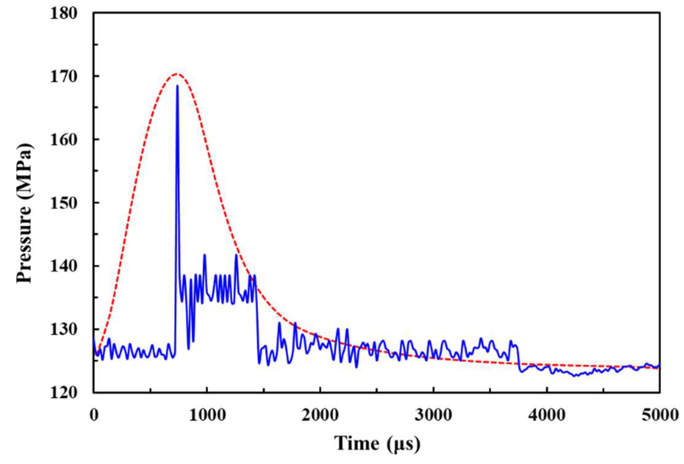
The pressure-time curve can be drawn by extracting data from the annulus of the wellbore according in the unit. Figure 7 shows the wellbore bottom pressure-time curves, in which the blue solid line is the wellbore bottom pressure-time curve by extracting data from the simulated result, and the red dashed line is calculated by the perforation software by inputting relevant parameters. The blue solid line shows that as the pressure wave arrives at the bottom of the wellbore, the wellbore pressure increases sharply, rapidly reaching its peak value (168.72 MPa) within hundreds of microseconds. As the pressure wave continues to propagate upward, its pressure value drops instantaneously and shows a trend of oscillation attenuation, as a result of the reflection in the wellbore. When the pressure value drops to the same level as the formation pressure, it tends to be stable gradually. This pressure-time curve is basically consistent with the variation law of pressure with time in the actual downhole perforation process. The red dashed line tends to rise first and then decrease, which the rising stage is very steep, and it drops rapidly after reaching the peak pressure (172.5 MPa), and when it falls near formation pressure, it tends to be gentle. The fluctuation range of the two curves is similar, and the curve simulated by perforation software are more regular, both of them can basically reflect the law of perforation pressure changing with time. The difference between the peak pressure values obtained by the two methods is within a reasonable range, which indicates that the modeling, meshing, and numerical simulation calculation are accurate, effective and reasonable. Therefore, a large number of numerical simulation based on the above simulation process can be carried out by changing different model parameters.
3.2.2. Propagation of Perforating Shock Loads
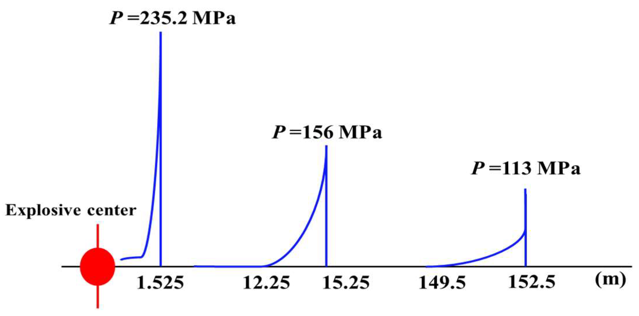
At present, there is a lack of research on the propagation law of perforation shock loads in the wellbore. However, there are many studies on underwater explosion shock wave propagation, and the theory of underwater explosion is mature. The explosive overpressure was studied in the book “Explosives in Water”, and the physical effects, basic laws and experimental methods of underwater explosion are reported. The theory of explosive-induced shock wave proposed is still widely used at present [36]. When the explosive explodes underwater, the detonation products of high temperature and high pressure are formed in the volume of the charge, and the pressure is far greater than the static pressure of the surrounding medium, resulting in the shock wave and bubble pulsation in water. With the propagation of the shock wave in water, the pressure and velocity of wave front decrease rapidly, and the waveform widens continuously [37]. As the low compressibility and high density of water, which can be regarded as an incompressible medium under overpressure. The propagation of shock wave and reflection wave in water can be approximately regarded as conforming to the law of acoustic theory, the attenuation of its propagation obeys exponential attenuation, which is verified by the data of underwater explosion experiment, as shown in Figure 8 [38]. Similarly, the detonation products formed by the explosion of the perforating charge rapidly expand in the perforation fluid in the form of gas. Since its initial pressure is far greater than the static pressure of the surrounding medium, the shock wave is formed in the wellbore, and the attenuation model of which in perforation fluid basically accords with the exponential attenuation mode.
According to the method of undetermined coefficients, the attenuation formula of the perforating shock wave in the wellbore can be set as Equation (12):
where is the perforating peak pressure after attenuation; is the perforating peak pressure at the bottom of tubing interval; is the attenuation index; is the unknown coefficient; is the distance from the position to the bottom of the tubing.
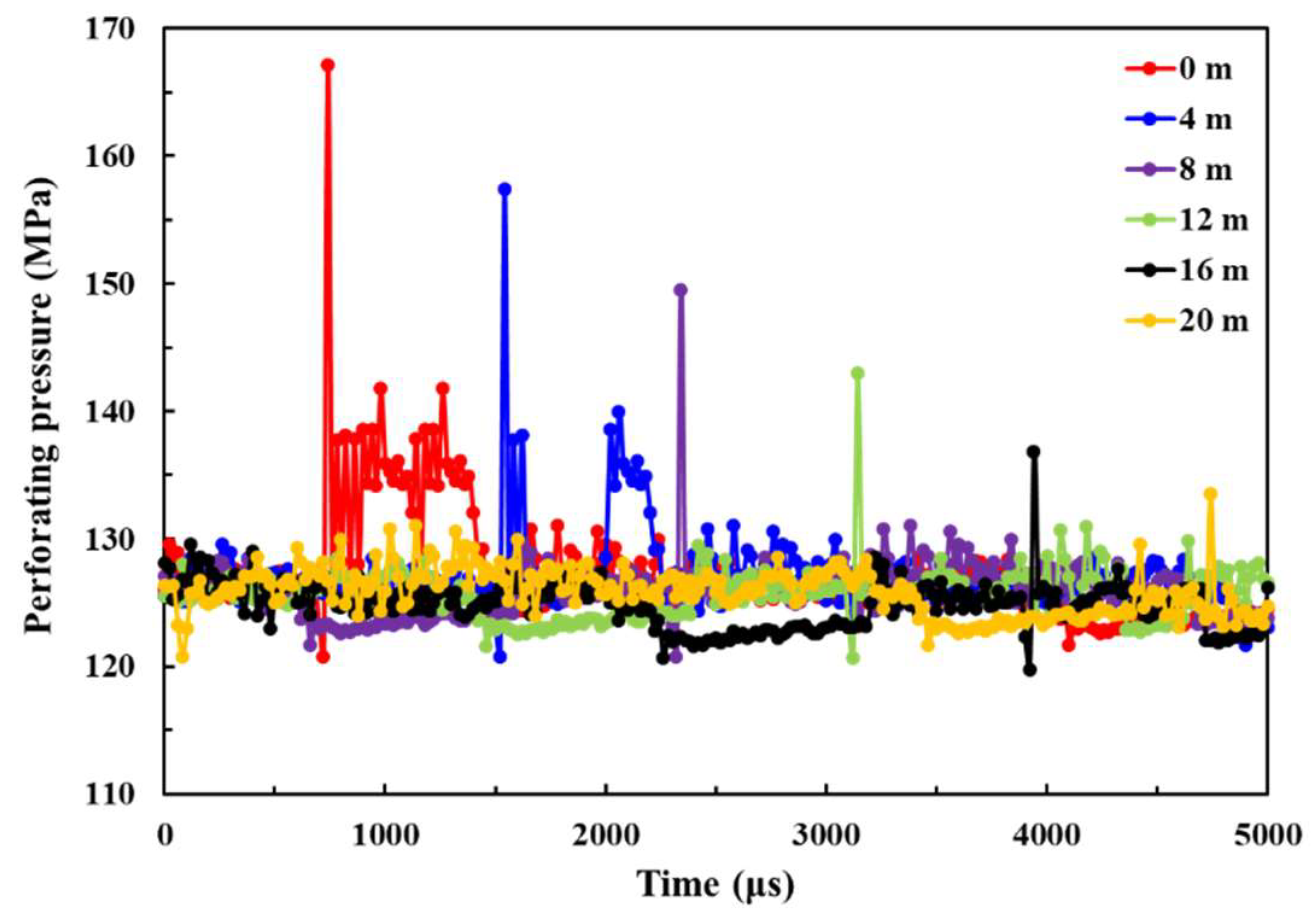
In order to solve the undetermined coefficients of the formula, the perforating pressure data at different positions in the wellbore can be extracted, as shown in Figure 9. These pressure curves vary similarly with different positions of the wellbore, which show that the perforation pressure at where increases first to the peak when the shock wave arrives, and as the shock wave continues to propagate upward, its pressure value drops instantaneously and shows a trend of oscillation attenuation until reaches the approximate stable state. The previous study shows that the effect of perforating shock wave on the perforated string is mainly considered the influence of peak overpressure. Figure 9 shows that the peak pressure attenuates with the increase of the upward distance along the wellbore from the initial position, which is the bottom of the tubing.
Based on the above numerical simulation data, the undetermined coefficients of the formula can be solved by using least squares fitting, as shown in Equation (13):
In order to obtain the perforating shock loads at the bottom of the tubing, a large number of numerical simulations can be carried out by changing the number of perforating bullets, charge per hole, tubing length, rathole length, formation pressure, and wellbore initial pressure. According to the simulation calculation results, a database can be established. The basic expression form of the function containing several unknowns can be established in Equation (14):
Based on the principle of the least square method, the modified multivariate nonlinear regression model has been established through MATLAB calculation code, the fitting formulas of the perforating shock loads at the bottom of the tubing interval can be obtained as Equation (15):
where is the wellbore initial pressure; is the formation pressure; is the parameters of strain rate; is the rathole length; is the number of perforating bullets; is the charge per hole.
The final calculation model to predict the perforating shock loads at different positions of the tubing interval can be obtained, as shown in Equation (16):
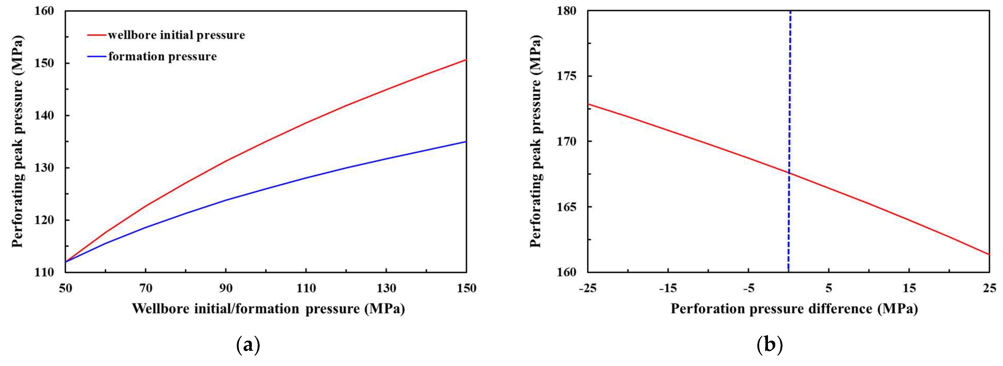
The formula analysis shows that the more the number of perforating bullets are, the larger the charge per hole is, the stronger the perforating shock loads is. The longer the tubing length and rathole length are, the weaker perforating shock loads are, this is because the larger wellbore space provides more room for explosive energy release, the formed shock loads are smaller. The higher the wellbore initial pressure and formation pressure are, the larger the peak perforating pressure is, and with the increase of wellbore initial pressure, the peak pressure increases obviously, the formation pressure increases, and the peak pressure increases relatively smaller, as shown in Figure 10a. This is because the hydrostatic pressure of wellbore fluid provides the initial load for the perforating dynamic load, which the wellbore initial pressure is an important factor affecting the perforating shock loads.
Figure 10b shows that as the pressure difference from negative to positive, the peak pressure of perforating gradually decreases, which means that the peak pressure during underbalanced perforation is slightly larger than that of underbalanced or balanced conditions. This is because that the explosive energy will be more hardly spread to the formation during underbalanced, which can increase the shock loads in the wellbore. It proves that most wells are susceptible to perforating shock damage under the condition of underbalance perforation for ultra-deep wells.
3.2.3. Dynamic Response of Perforated String
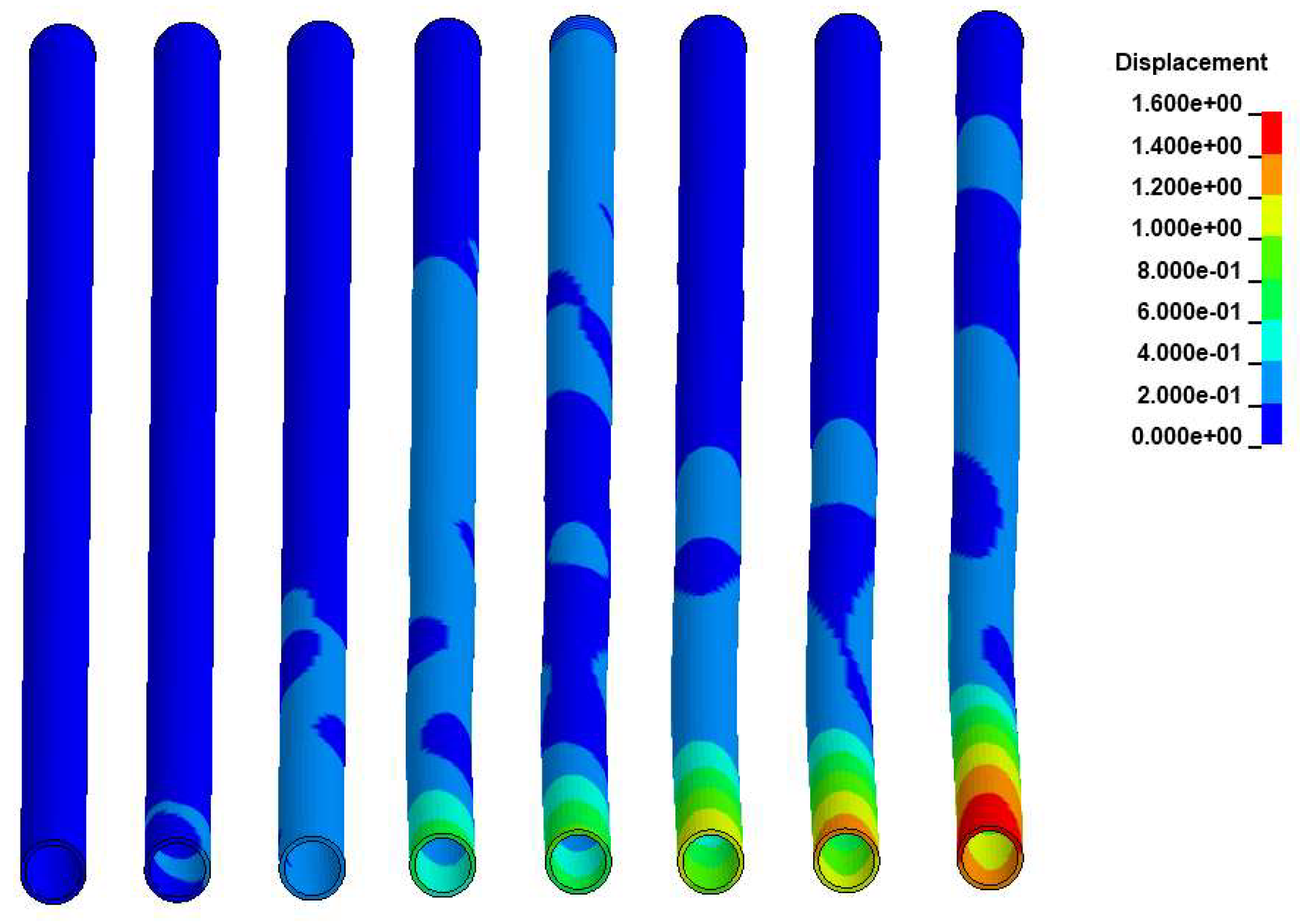
With the strong shock loads and fluid-structure interaction, perforated pipe string will be in a very complex state of stress and strain for ultra-deep wells, some research was carried out to study the failure mechanism of perforated string with shock loads [39,40]. In order to present the dynamic response process of the string more clearly, the nephograms of displacement change during perforating at different times are grouped together in one, as shown in Figure 11. It can be seen that when the shock waves come to the tubing interval in the wellbore, the shock loads act on the bottom of the string and transfers upward, with the displacement occurring at the bottom part of the string and accumulating gradually. The shock loads are transmitted upward the string and the energy is gradually absorbed by the string, which finally becomes the strain energy of the string. The maximum displacement appears at the bottom of the string, the shock loads cannot propagate further as the top restricted, with no displacement occurring at the top of the string.
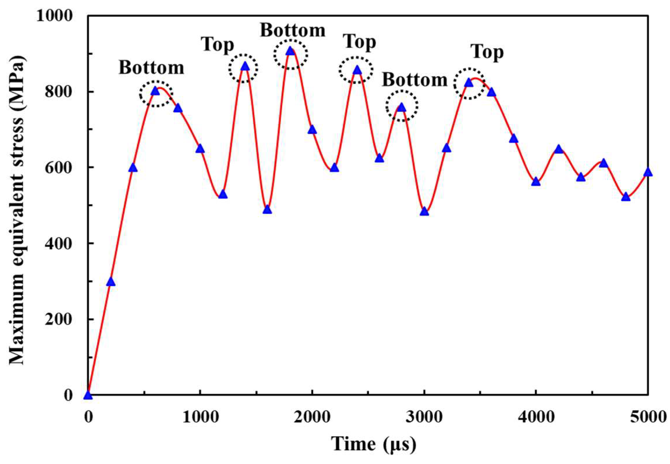
The maximum equivalent stress changing over time curve can be drawn by extracting data from a structural block (part) at the perforated string, as shown in Figure 12.
It can be seen the equivalent stress of the string presents a periodic change, the bottom of the string responds firstly after the detonation of the perforating shaped charge, with the first peak point (802 MPa). Then the equivalent stress reaches the extreme value at the top of the string where is the fixed end, with the second peak point (868 MPa). Subsequently, the shock waves reflect downwards and the maximum value (908 MPa) appears at the bottom, which is one cycle. The shock waves reflect at the bottom of the string and will enter the next cycle. It can be concluded that the maximum equivalent stress appears at the bottom and top of the string, which the bottom is the initial output unit of perforating shock loads, and the top is restricted with the loads reflected and enhanced. From the aspect of the changing trend of equivalent stress, it can be known that the maximum equivalent stress still shows periodic variation, which fluctuates back and forth between the bottom and the top of the string, with the maximum value repeatedly appears at the bottom and top of the string, which can be assessed as vulnerable parts. In a well sealing section, the bottom of the tubing can be used as the initial position of the perforating shock loads acting on the string, the top of the tubing is the position of the packer.
A structural block (part) at the bottom of the string is built to obtain the data of dynamic response of the perforated string. Table 2 shows the acceleration peaks and maximum displacements of the perforated string in the axial, radial X and radial Y directions at the bottom of the perforated string respectively. The greatest dynamic response appears in the axial direction, which the acceleration peak and maximum displacement are both much greater than the other two directions. These in the radial X direction are slightly greater than that in the radial Y direction, while there are little differences between radial X and radial Y directions. Assuming the shock loads (Figure 7) act on the string in the axial direction. The axial displacement of perforated string can be calculated by Equation (14), the result shows that the maximum displacements are ±6.8 cm, much greater than simulation results. The reason is that the string material has the ability to absorb the shock loads of perforation, and the theoretical calculations often do not take this into account.
Through the above analysis, with such the strong cyclical axial shock loads, the perforated string will show buckling instability or even fracture in the macroscopic, which usually oscillates due to the changing radial load, resulting in a significant shear load on the string. Therefore, it is necessary to install the axial shock absorbers below the packer to reduce the impact vibration on it and the upper instruments.
4. Optimization Measures
Common shock absorbers are mostly connected by spring or rubber elements in series, or the combination of the two elements for shock absorption. The shock absorbers based on the principle of rubber cylinder is equipped with two rubber cylinders, and the elastic function of rubber is used to achieve the purpose of shock absorption. As the outer diameter of the rubber drum is much smaller than the inner diameter of the oil casing, which the shock absorption effect is not good. For the ultra-deep well perforation, the temperature and pressure at the bottom of the wellbore are relatively high, which make the rubber components in the shock absorber more easily for serious damage, and the maintenance is troublesome with no reused. In order to ensure the shock absorption effect in such an environment, the shock absorber based on spring shock absorption principle is adopted, which can close to the inner wall of the casing and greatly reduce the axial vibration caused by perforation shock loads.
4.1. Design of Shock Absorption
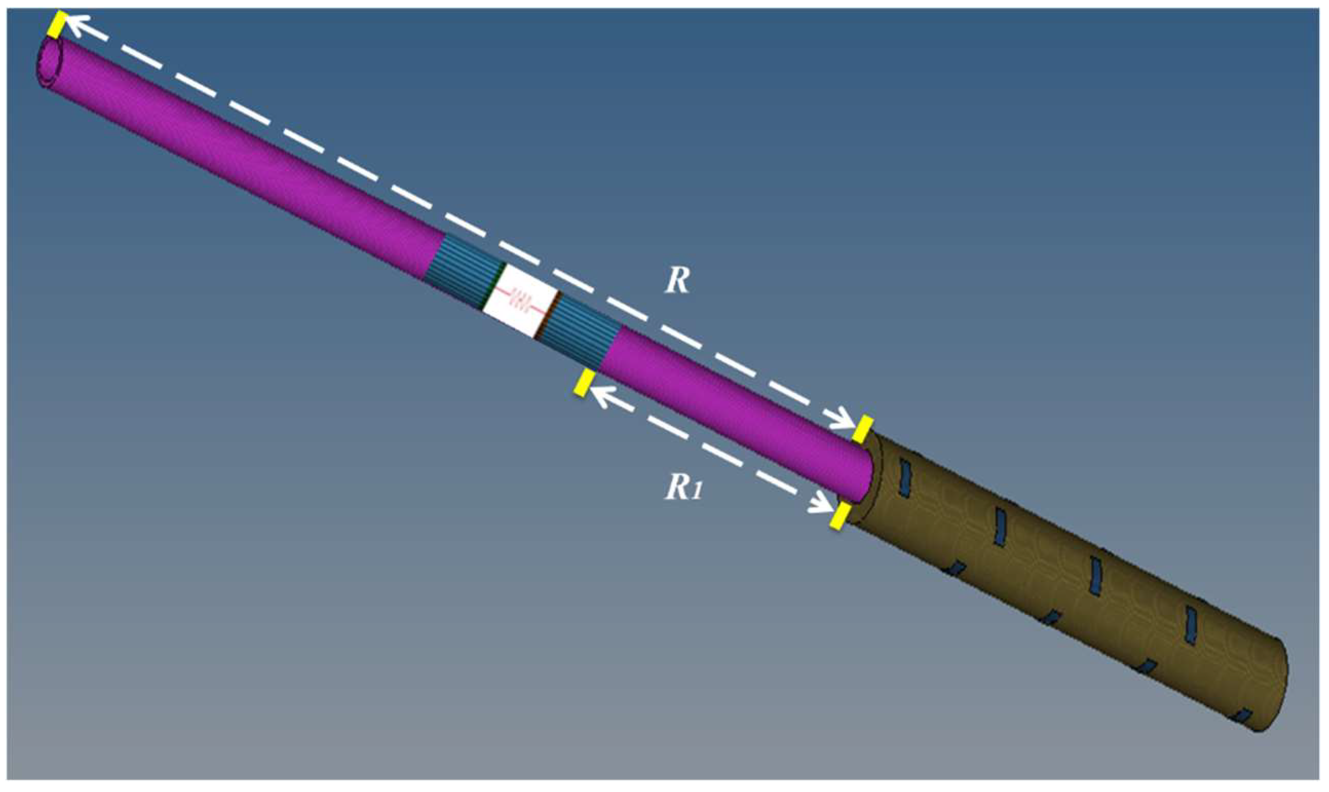
In order to achieve the best shock absorption effect, the installation position of shock absorbers can be optimized by numerical simulation, which can be simplified as a mechanical spring element adding the axial shock to the numerical model. The distance between the shock absorber and the perforating gun is R1 and the ratio of the distance between the shock absorber and the perforating gun to the distance of the packer is R1/R, as shown in Figure 13. The position proportional parameters are shown in Table 3.
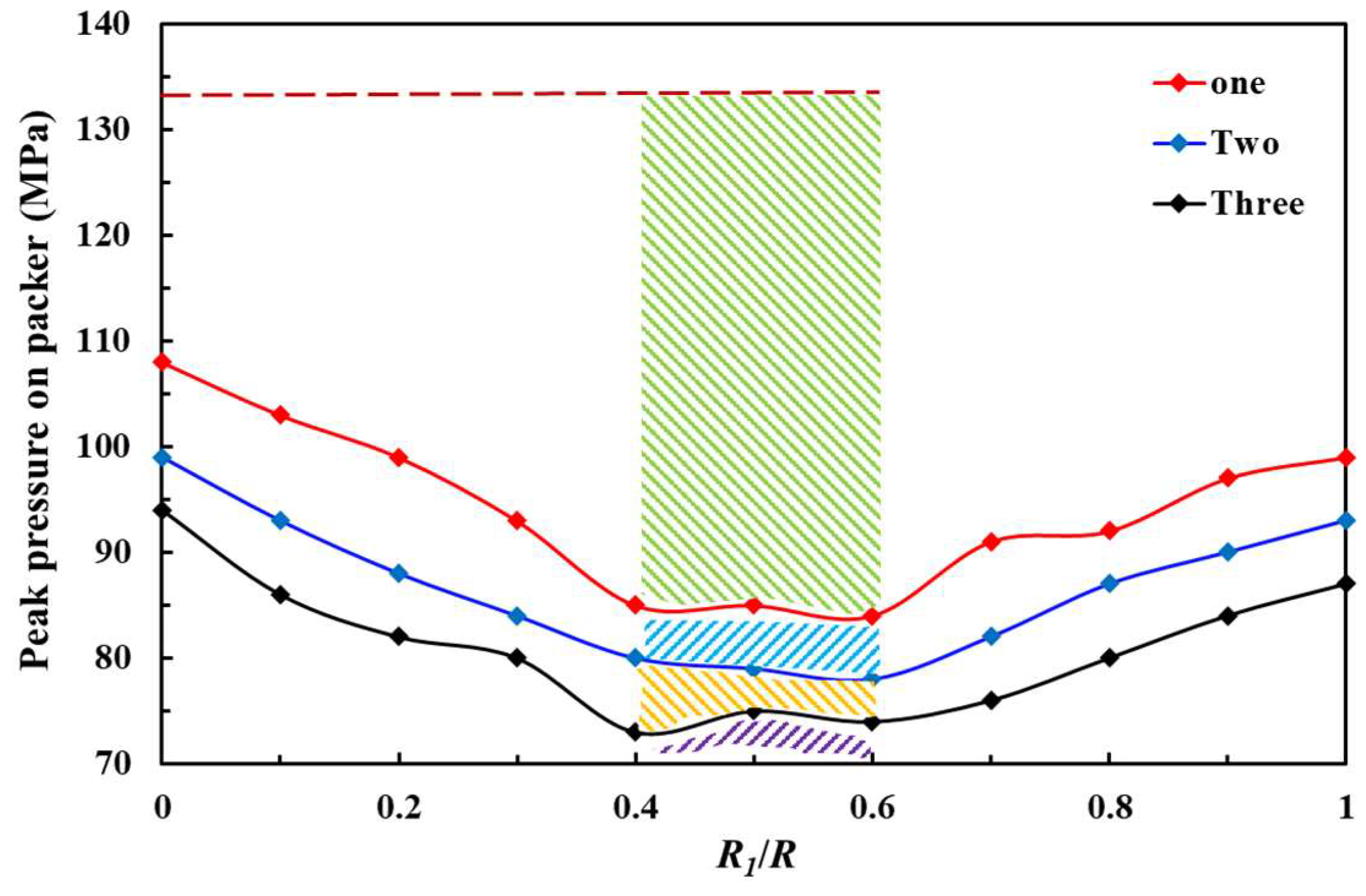
According to the method of modeling, meshing and numerical simulation in Section 3.1, several groups of numerical simulation calculations are carried out. Based on the simulation results, the curves of peak pressure on packer during perforating with different numbers of shock absorbers under different installation positions can be obtained, as shown in Figure 14.
The red dashed line represents the peak pressure (133.79 MPa) on the packer without the installation of shock absorbers. Three solid lines of different colors represent the peak pressure of the packer with different numbers of shock absorbers. The colorful area represents the reduction of the peak pressure on the packer, which decreases significantly with the installation of one shock absorber, the effect of shock absorption is obvious. When the numbers of shock absorbers are two or three, the peak pressure on the packer continues to decrease, but the reduction is smaller. When the installation positions of shock absorbers are in the colorful area (R1/R = 0.4–0.6), the peak pressure on the packer decreases the most and the shock absorption effect is the best. It shows that the best shock absorption effect can be achieved by optimizing the installation positions of shock absorbers, which is the middle of the perforated string connecting the packer and perforating gun. In order to meet the needs of the practical application, the formula for reducing the peak pressure on the packer can be fitted with condensing different installation positions and different number of shock absorbers, as shown in Equation (17):
where are the reduction values of perforating peak pressure on the packer with one, two, three shock absorbers, respectively.
With the installation of shock absorbers, the peak pressure on the packer is still large, which may exceed the pressure range of the general packer and pose a serious threat to the safety of the packer. Therefore, it is necessary to analyze the safety of the packer during perforating for ultra-deep wells.
4.2. Safety Analysis of Packer
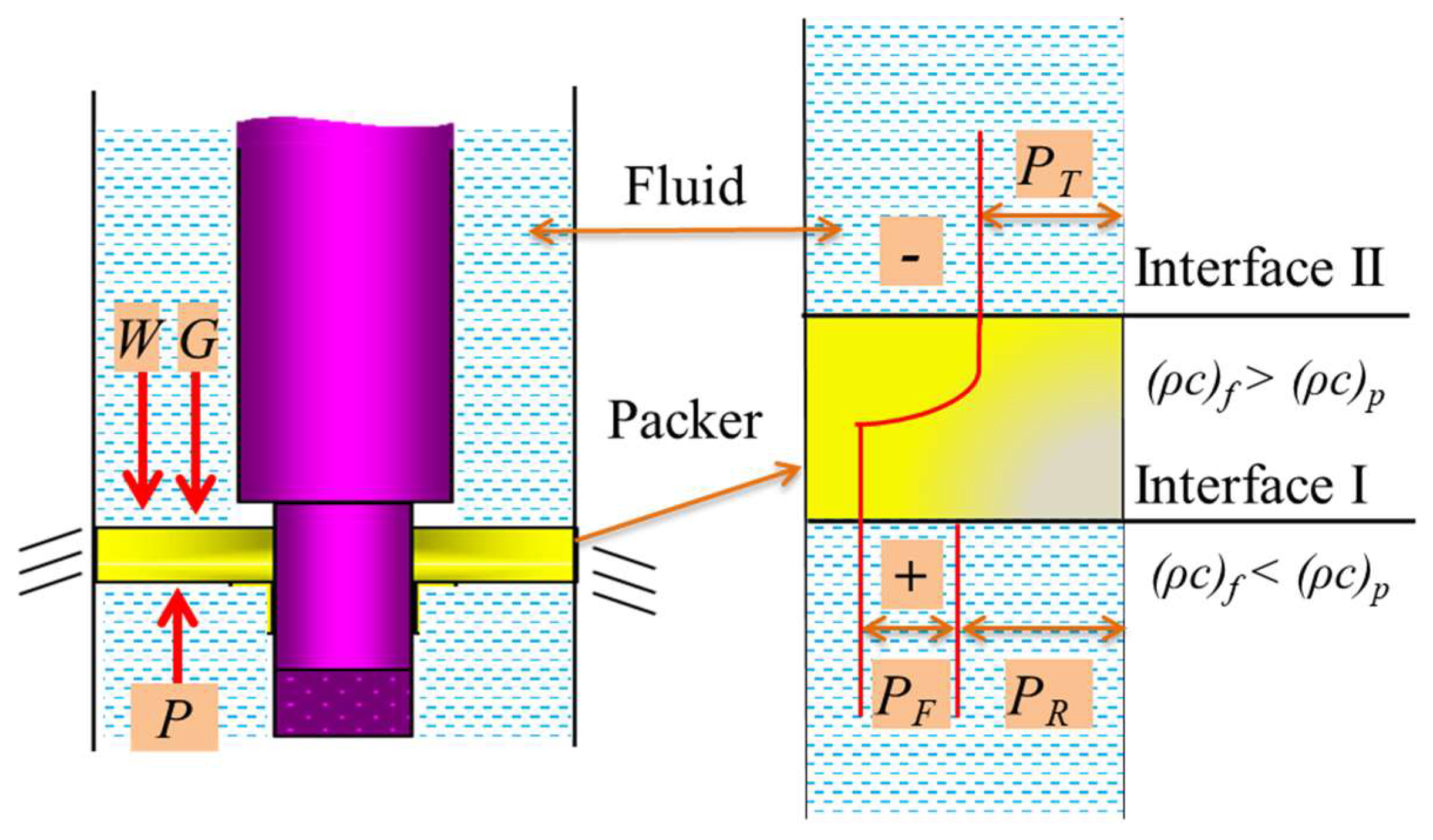
The dynamic response process of the packer under perforating shock loads is a very complex process. In this study, only the downhole sealing capacity of packer is studied, which mainly bears the function of maintaining pressure. By regarding the wellbore fluid as the medium of pressure transmission, without considering the fluid-solid interaction between the fluid and the solid structure of packer, according to the technical index of packer products, the safety of the packer can be studied. In addition to its own bearing capacity of the packer load level, the upper-end surface of the packer also needs to withstand the pressure of the fluid column in the well, and the lower end surface needs to withstand the perforating shock loads, as shown in the left of Figure 15. As the packer is placed in the fluid medium, there are two interfaces, and when the shock loads propagate in the wellbore fluid, it will reflect and transmit when encountering the packer, as shown in the right of Figure 15.
The carrying capacity of the packer can be expressed as Equation (18):
where is the bearing capacity of the packer; is the cross section area of the packer; is the liquid column gravity on the packer.
As the reflection of the packer will increase the pressure, the perforating pressure on the packer is the difference between the overpressure of the pressure wave and the pressure of transmitted wave [41], which can be expressed in Equation (19):
where is the reflected pressure by the packer; is the transmission pressure by the packer; is the impact resistance parameters of water medium at normal temperature and pressure; is the impact resistance parameters of rubber medium at normal temperature and pressure.
The incident pressure can be calculated by Equation (16), and the final peak pressure on the packer after during perforating can be obtained by Equation (20):
From the above analysis, combining Equation (17) with Equation (20), the pressure difference between the upper and lower end of the packer can be calculated by Equation (21):
5. Case Study
The field case is an ultra-deep well located in the western part of China. The well depth is 8000 m; perforation interval is 7965–7980 m, the operation parameters during perforating are shown in Table 4. The type of the packer is static type packer, which has strong pressure resistance and the rated working pressure is 70 MPa. Based on these actual parameters of the field example, the method presented in this paper can be used to analyze and optimize the perforation safety.
According to the strength check theory of the pipe string, the maximum allowable peak pressure can be calculated by Equation (22). The internal pressure strength of the tubing is 79 MPa, the safety coefficient of internal pressure strength is 1.25, the minimum external pressure of perforated string is provided by wellbore fluid, which is calculated as water:
where Pmax is the permissible maximum peak pressure on the tubing; Ppi is the internal pressure strength of the tubing; Krpi is the safety coefficient of internal pressure strength; Ep is the plastic hardening modulus; P0 is the local pressure outside the tubing.
The permissible maximum peak value of perforation calculated by Equation (22) is 132.83 MPa. Through the analysis of Section 3.2, considering the bottom of the tubing and the packer as the object of the safety analysis of the perforated string system. The perforating peak pressure at the bottom of the tubing interval calculated by Equation (15) is 150.84 MPa, which exceeds the maximum peak pressure calculated above. The result shows that the tubing will be damaged due to excessive negative pressure difference. The peak pressure propagating to the top of the tubing (packer) after attenuation calculated by Equation (16) is 90.86 MPa, the pressure difference between the upper and lower end of the packer calculated by Equation (21) is 117.17 MPa, which exceeds the pressure range of the packer (70 MPa) and poses a serious threat to the safety of the packer.
Based on the optimization method of shock absorption proposed in this paper, the design of shock absorption is carried out for the case, as shown in Table 5. It shows that when the shock absorbers are installed, the peak pressure at the bottom of the tubing is reduced to the allowable peak range, the safety of perforated string is ensured. When three shock absorbers are installed at 22.5 m from the top of the perforating gun, the shock absorption effect is the best, the value is reduced to the lowest (117.51 MPa). However, when the pressure difference between the upper and lower of the packer is reduced to the lowest (84.19 MPa), the value still exceeds the pressure-bearing capacity of the packer. Therefore, the further optimization is needed.
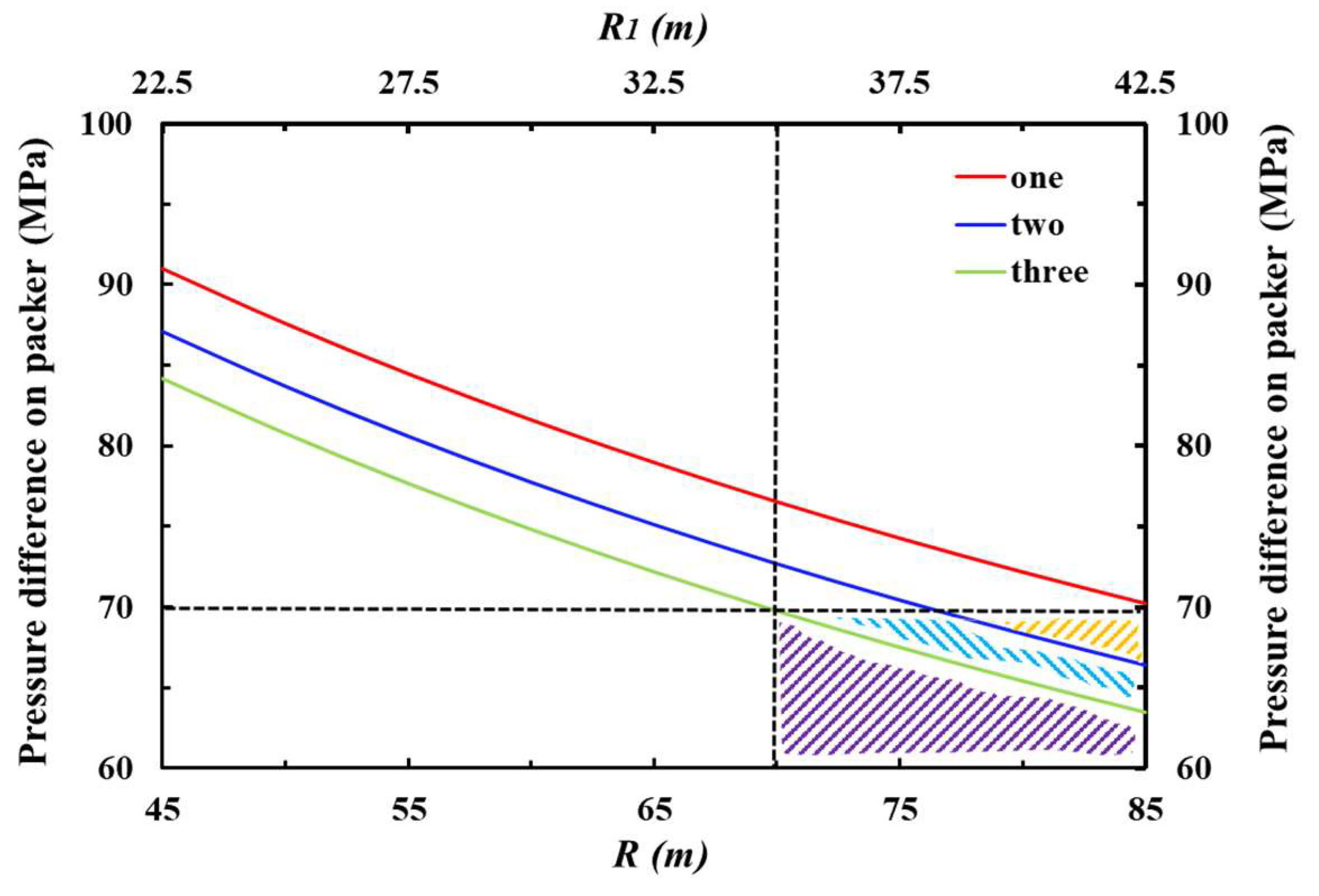
The method of optimizing the set distance of the packer is used to ensure the safety of the packer, which the safe distance of packer can be calculated by Equation (26), the final optimization design is shown in Figure 16. Three solid lines of different colors represent pressure difference on the packer with different numbers of shock absorbers. The black horizontal dashed line represents the maximum pressure-bearing capacity of the packer (70 MPa). The black vertical dashed line is an auxiliary line. The colorful area represents the packer is safe when the parameters are within a reasonable range, which the set distance of the packer is 69.46–85 m with two or three shock absorbers installing from the distance 35–42.5 m to the perforating gun.
Through the above analysis, the following optimization scheme was adopted in the field case: the packer is set 75 m away from the perforating gun; two shock absorbers are mounted in series in the middle of the tubing, which is 37.5 m away from the perforating gun. On this basis, the perforation test operation proceeded smoothly, and there was no safety problem of perforation string system and packer, which have a good effect on field application and improve the safety of perforation. In addition to the above optimization measures, it is suggested that better shock resistant materials should be used for pipe string, packer, and other instruments, with thicker wall thickness.
6. Conclusions
By combining theory with numerical simulation, this study proposes a new method for the study of perforating shock loads and the effects on the perforated string and packer for ultra-deep wells, the related optimization measures are put forward, which can provide important guidance for the design of field perforation operations and to improve security. Based on the analysis, some conclusions are reached:
- (1)
- Through mechanical analysis, dynamic models in the axial, radial and circumferential directions have been established preliminarily, by which the displacement of perforated strings under axial shock loads can be calculated.
- (2)
- The propagation attenuation law of shock loads in the wellbore is obtained, a multi-factors prediction model of which is presented, which shows that the wellbore initial pressure provides the basis for the perforating dynamic pressure, and the shock damage is more obvious with negative perforating pressure.
- (3)
- It is found that the vulnerable parts of the perforated string system are the bottom of the tubing and the position of the packer, and the axial dynamic response of which is the largest with shock loads.
- (4)
- A shock absorption design based on optimizing the installation position and number of shock absorbers is proposed, and the pressure difference on the packer can be calculated.
- (5)
- The case study shows that the optimization methods proposed in this paper are practical, as the shock damage can be greatly reduced by combining shock absorption with a safe distance of the downhole packer.
Author Contributions
All the authors conceived and designed the study. Formal analysis, Q.D. and H.Z.; Software, Q.D. and H.Z.; Writing—original draft, Q.D. and H.Z.; Writing—review & editing, J.L., X.H. and H.W.
Acknowledgments
The authors gratefully acknowledge the Natural Science Foundation of China (Grant No. U1762211, Grant No. 51734010, Grant No. 51574262, Grant No.51774304, Grant No. 51774063), National Oil and Gas Major Project (Grant No. 2017ZX05009), the Foundation for Innovative Research Groups of the National Natural Science Foundation of China (Grant No. 51521063), the State Key Laboratory of Petroleum Resources and Engineering.
Conflicts of Interest
The authors declare that there is no conflict of interests regarding the publication of this paper.
Nomenclature
| Density of perforated string | |
| Cross sectional area of perforated string | |
| Elasticity modulus of perforated string | |
| Damping coefficient of perforated string in the fluid | |
| Force acting on perforated string | |
| Perforating pressure | |
| Unit impulse function | |
| Inertia moment of perforated string | |
| Shear modulus of perforated string | |
| Polar moment of inertia of a cross section of perforated string | |
| Constant | |
| Positive number | |
| Positive integer | |
| Natural frequencies | |
| Time integral variable | |
| Intrinsic angular frequency | |
| Radial displacement of perforated string | |
| Axial displacement of perforated string | |
| Angular displacement of perforated string | |
| Function of time | |
| Longitudinal vibration amplitude of the section from the origin of pipe string | |
| Yield stress | |
| Initial yield stress | |
| Strain rate | |
| Effective plastic strain | |
| Parameters of strain rate | |
| Relative volume | |
| Initial internal energy of unit explosive volume | |
| Physical parameters of explosive | |
| Perforating peak pressure after attenuation | |
| Perforating peak pressure at the bottom of tubing interval | |
| Attenuation index | |
| Distance from the position to the bottom of the tubing | |
| Unknown coefficient | |
| Wellbore initial pressure | |
| Formation pressure | |
| Tubing length | |
| Rathole length | |
| Number of perforating bullets | |
| Charge per hole | |
| Perforating peak pressure reduction on the packer with one, two, three shock absorbers | |
| Bearing capacity of the packer | |
| Cross section area of the packer | |
| Liquid column gravity on the packer | |
| Reflected pressure by the packer | |
| Transmission pressure by the packer | |
| Impact resistance parameters of water medium at normal temperature and pressure | |
| Impact resistance parameters of rubber medium at normal temperature and pressure | |
| Permissible maximum peak pressure on the tubing | |
| Internal pressure strength of the tubing | |
| Safety coefficient of internal pressure strength | |
| Local pressure outside tubing |
Appendix A
Based on the model of perforated string with the boundary and initial conditions in Section 2, the longitudinal free vibration equation of the perforated string can be established in Equation (A1):
Assuming that all the points on the perforated string move synchronously, the method of separating variables can be used to assume in Equation (A2);
where is the function of time; is the longitudinal vibration amplitude of the section at the point of x from the origin of the pipe string. Equtaion (A2) can be changed into Equation (A3).
where is a constant. If , Equation (A3) has a non-zero solution. The natural frequencies and principal modes of perforated pipe string can be obtained by solving a linear differential equation with constant coefficients. Making , the natural frequency and the main modes of the perforated pipe string can be obtained in Equation (A4) and Equation (A5):
where is the positive number; are positive integers; is the natural frequencies, ; is the intrinsic angular frequency, rad/s.
For solving the axial mechanical model, assuming the shock loads of perforation act on the string in the axial direction. The generalized force can be expressed in Equation (A6):
As the coordinate transformation does not affect the initial condition, which is still zero. The infinite series of sinusoidal vibration modes can be used to express the displacement response of perforated string under axial shock loads, as shown in Equation (A7);
where is the time integral variable.
References
- Zhen, X.; Moan, T.; Gao, Z.; Huang, Y. Risk Assessment and Reduction for an Innovative Subsurface Well Completion System. Energies 2018, 11, 1306. [Google Scholar] [CrossRef]
- Schatz, J.F.; Folse, K.C.; Fripp, M.; Dupont, R. High-Speed Pressure and Accelerometer Measurements Characterize Dynamic Behavior during Perforating Events in Deepwater Gulf of Mexico. In Proceedings of the SPE Annual Technical Conference and Exhibition, Houston, TX, USA, 26–29 September 2004. SPE-90042-MS. [Google Scholar] [CrossRef]
- Xu, C. Numerical Analysis and Model Establishment of Dynamic Response of Perforating String. Master’s Thesis, Xi’an Shiyou University, Xi’an, China, 2017. [Google Scholar]
- Gilliat, J.; Bale, D.; Satti, R.P.; Li, C.; Howard, J.J. The Importance of Pre-Job Shock Modeling as a Risk Mitigation Tool in TCP Operations. In Proceedings of the SPE Deepwater Drilling and Completions Conference, Galveston, TX, USA, 10–11 September 2014. SPE-170260-MS. [Google Scholar] [CrossRef]
- Baumann, C.E.; Dutertre, A.; Martin, A.; Williams, H. Risk Evaluation Technique for Tubing-Conveyed Perforating. In Proceedings of the SPE Europec/EAGE Annual Conference, Copenhagen, Denmark, 4–7 June 2012. [Google Scholar] [CrossRef]
- Lu, D.T.; Xu, G.M.; Kong, X.Y. Calculating Transient Pressure of Wellbore Taking under Perforation Condition with Parallel Computation Method. Univ. Sci. Technol. China 1999, 29, 638–643. [Google Scholar]
- Yin, H.D.; Zhang, J.J.; Li, S.Y. Mechanics Analysis of Perforating Combined Well Testing String and Protection Technology of Downhole Instrument. Oil. Drilling. Prod. Techno. 2003, 25, 61–63. [Google Scholar]
- Yu, Z.D.; Li, Y. Finite Clearance Element Analysis of Perforation Tube String for Testing for Oil. Chinese J. Appl. Mech. 2003, 20, 73–77. [Google Scholar]
- Dou, Y.H.; Li, M.F.; Zhang, F.X.; Yang, X.T. An Analysis of the Effect of the Well Bore Structure on the Strength Safety of the Tubing String at the Perforation Section. China Pet. Mach. 2012, 40, 27–29. [Google Scholar]
- Xu, F.; Li, M.F.; Dou, Y.H.; Zhang, F.X.; Yang, X.T. The Analysis of the Influence of Perforating Parameters on the Strength Security of Perforation String. 12. Appl. Mech. Mater. 2013, 268, 514–517. [Google Scholar] [CrossRef]
- Yang, X.T.; Zhang, F.X.; Li, M.F.; Dou, Y.H. Analysis of strength safety of perforated string considering detonation parameters. Adv. Mater. Res. 2013, 634, 3573–3576. [Google Scholar] [CrossRef]
- Zhang, W.B.; Xie, S.; Lu, Q. Influencing Analysis of Perforation Impact Load on Combined String of Perforation-acidification-test. Well Test. 2016, 25, 8–11. [Google Scholar]
- Zhou, H.F.; Ma, F.; Chen, H.B.; Xu, Y.X.; Xi, LX.; W, S.S. Comprehensive dynamic load test for the column in perforation section. Well Logging Technol. 2014, 38, 247–250. [Google Scholar]
- Lu, X.; Wang, S.S.; Ma, F.; Zhou, H.F. Dynamic responses test of perforating string section under explosion impact. Sci. Technol. Eng. 2014, 14, 53–56. [Google Scholar]
- Chen, F.; Chen, H.B.; Tang, K. Influence of Perforating Impact Load on the Operating String and the Countermeasures. Nat. Gas Ind. 2010, 30, 61–65. [Google Scholar]
- Chen, H.B.; Tang, K.; Ren, G.H. String Dynamic Mechanics Analysis on Ultra-Deep Perforation. Well. Logging Technol. 2010, 34, 487–491. [Google Scholar]
- Baumann, C.E.; Pesantes, E.; Guerra, J.; William, A.; Williams, H. Reduction of Perforating Gunshock Loads. SPE Drill. Complet. 2012, 27, 65–74. [Google Scholar] [CrossRef]
- Teng, Y.S. Dynamic Simulation for Perforating and String Safety Evaluation. Master’s Thesis, China University of Petroleum (East China), Beijing, China, 2014. [Google Scholar]
- Kang, K.; Ma, F.; Zhou, H.F. Study on Dynamic Numerical Simulation of String Damage Rules in Oil-gas Well Perforating Job. Procedia Eng. 2014, 84, 898–905. [Google Scholar] [Green Version]
- Cai, L.Z.; Zhao, H.; Xue, S.F.; Yang, Z.Z. Dynamic Response Analysis of String Structure during Perforating Process. Oil Field Equip. 2015, 44, 26–30. [Google Scholar]
- Yang, Z.Z. Dynamic Response of String under Perforating Pulse Load. Master’s Thesis, China University of Petroleum (East China), Beijing, China, 2015. [Google Scholar]
- Zhang, W.; Xu, C.; Li, M.F.; Zhang, L.; Wang, G.Q. Transient Response and Strength Analysis of Perforating String. China Pet. Mach. 2017, 45, 90–94. [Google Scholar]
- Li, Z.F.; Zhang, C.Y.; Song, G.M. Research Advances and Debates on Tubular Mechanics in Oil and Gas Wells. J. Pet. Sci. Eng. 2017, 151, 194–212. [Google Scholar] [CrossRef]
- Li, B.Y. Analysis of Strength and Safety of Packer Central Tube under Perforating Impact Loading. Master’s Thesis, Xi’an Shiyou University, Xi’an, China, 2018. [Google Scholar]
- Li, M.F.; Xu, F.; Dou, Y.H. Measurement of Perforating Column Vibration Parameters and ALE-based Numerical Simulation. Chin. J. Appl. Mech. 2019, 36, 458–465. [Google Scholar]
- Baumann, C.E. An HP-Adaptive Discontinuous Finite Element Method for Computational Fluid Dynamics. Ph.D. Dissertation, the University of Texas at Austin, Austin, TX, USA, 1997. [Google Scholar]
- Baumann, C.E.; Oden, J.T. An Adaptive-order Discontinuous Galerkin Method for the Solution of the Euler Equations of Gas Dynamics. Int. J. Num. Methods Eng. 2000, 47, 61–73. [Google Scholar] [CrossRef]
- Burman, J.; Schoener-Scott, M.F.; Le, C.V. Predicting Wellbore Dynamic-Shock Loads Prior to Perforating. In Proceedings of the Brasil Offshore Conference and Exhibition, Macaé, Brazil, 14–17 September 2011. SPE-143787-MS. [Google Scholar] [CrossRef]
- Bale, D.; Ji, M.; Satti, R.; Gilliat, J. Advances in Numerical Modeling of Downhole Dynamics for Perforated Well Completions. In Proceedings of the SPE Annual Caspian Technical Conference and Exhibition, Astana, Kazakhstan, 12–14 November 2013. SPE-172308-MS. [Google Scholar] [CrossRef]
- Bale, D.; Satti, R.; Ji, M. A Next-generation Shock-capturing, Multi-phase Flow Simulator for Perforating Applications in HPHT Environment. In Proceedings of the SPE Deepwater Drilling & Completions Conference, Galveston, TX, USA, 14–15 September 2016. SPE-180283-MS. [Google Scholar] [CrossRef]
- Katayama, M.; Kibe, S. Numerical Study of the Conical Shaped Charge for Space Debris Impact. Int. J. Impact Eng. 2001, 26, 357–368. [Google Scholar] [CrossRef]
- Molinari, J.F. Finite Element Simulation of Shaped Charges. Finite Elem. Anal. Des. 2002, 38, 921–936. [Google Scholar] [CrossRef]
- Liu, J.; Guo, X.Q.; Liu, Z.J.; Liu, X.; Liu, Q.Y. Pressure Field Investigation into Oil & Gas Wellbore during Perforating Shaped Charge Explosion. J. Pet. Sci. Eng. 2019, 172, 1235–1247. [Google Scholar]
- Deng, Q.; Zhang, H.; Li, J.; Wang, H.; Cai, Z.Y.; Tan, T.Y.; Hou, X.J. A Model for Estimating Penetration Length under Different Conditions. In Proceedings of the 52nd US Rock Mechanics/Geomechanics Symposium, Seattle, WA, USA, 17–20 June 2018; ARMA-2018-344. American Rock Mechanics Association. Available online: https://www.onepetro.org/ conference-paper/ARMA-2018-344 (accessed on 1 June 2019).
- Deng, Q.; Zhang, H.; Li, J.; Hou, X.; Wang, H. Analysis of Impact Load on Tubing and Shock Absorption during Perforating. Open Phys. 2019, 17, 214–221. [Google Scholar] [CrossRef]
- Cole, R.H. Underwater Explosion; LISA Princeton University Press: Princeton, NJ, USA, 1948. [Google Scholar]
- Gao, Y.D.; Wang, S.H.; Wang, X.C.; Liu, Z.Y.; Guo, S.S.; Tang, J.J. Assessment Packer in Perforating String in Safety Distance. Well Logging Technol. 2016, 40, 382–384. [Google Scholar]
- Yu, Y.; R, F.Y. Application of Packer in Fracture Perforating. J. Xian Univ. Sci. Technol. 2007, 27, 423–425. [Google Scholar]
- Qiu, Q.; Cui, L. Reliability Evaluation Based on a Dependent Two-stage Failure Process with Competing Failures. Appl. Math. Model. 2018, 64, 699–712. [Google Scholar] [CrossRef]
- Qiu, Q.; Cui, L. Optimal Mission Abort Policy for Systems Subject to Random Shocks Based on Virtual Age Process. Reliab. Eng. Syst. Safe 2019, 189, 11–20. [Google Scholar] [CrossRef]
- Deng, Q.; Zhang, H.; Li, J.; Hou, X.; Wang, H. Safety Distances of Packers for Deep-water Tubing-conveyed Perforating. In Proceedings of the Offshore Technology Conference, Houston, TX, USA, 5–7 November 2018. OTC-28770-MS. [Google Scholar] [CrossRef]
Figure 1.
Tubing damage caused by perforating shock loads: (a) tubing breaking; (b) tube buckling.

Figure 2.
Structure of downhole tubing-conveyed perforation.

Figure 3.
Simplified physical model of perforated string: (a) sketch of mechanical analysis; (b) mechanical model of perforated string under axial shock loads.
Figure 3.
Simplified physical model of perforated string: (a) sketch of mechanical analysis; (b) mechanical model of perforated string under axial shock loads.

Figure 4.
Mechanical analysis of a perforated string element: (a) sketch of mechanical analysis under radial shock loads; (b) sketch of mechanical analysis under circumferential shock loads.
Figure 4.
Mechanical analysis of a perforated string element: (a) sketch of mechanical analysis under radial shock loads; (b) sketch of mechanical analysis under circumferential shock loads.

Figure 5.
Modeling and meshing: (a) model for numerical simulation; (b) cross-section view of mesh model.
Figure 5.
Modeling and meshing: (a) model for numerical simulation; (b) cross-section view of mesh model.

Figure 6.
Pressure variation of perforation gun section (units for contour plots: 1011 Pa).

Figure 7.
Wellbore bottom pressure-time curves.

Figure 8.
Data regularity curves of shock wave disseminating experiment tested in water.

Figure 9.
Pressure-time curves at different positions of the wellbore.

Figure 10.
Formula analysis: (a) Influence of wellbore initial and formation pressure on perforating pressure; (b) Influence of perforation pressure difference on perforating pressure.
Figure 10.
Formula analysis: (a) Influence of wellbore initial and formation pressure on perforating pressure; (b) Influence of perforation pressure difference on perforating pressure.

Figure 11.
Displacement of string during perforating.

Figure 12.
Maximum equivalent stress time-varying curve.

Figure 13.
Model for numerical simulation with shock absorber.

Figure 14.
Perforating pressure on packer with different shock absorber installation positions.

Figure 15.
Perforating pressure on packer with different installation positions of shock absorbers.

Figure 16.
Field case optimization design.


Table 1.
Explosive parameters.
| ρ0 (g/cm3) | D (cm/μs) | B (GPa) | C (GPa) | R1 | R2 | w | E1 | V1 |
|---|---|---|---|---|---|---|---|---|
| 1.69 | 0.8310 | 850 | 18 | 4.60 | 1.3 | 0.38 | 0.1 | 1.0 |
Table 2.
Acceleration peaks of perforated string in axial, radial X and radial Y.
| Direction | Peak (+)/10,000g | Peak (−)/10,000g | Displacement (+)/cm | Displacement (−)/cm |
|---|---|---|---|---|
| Axial | 6.32 | −6.17 | 4.54 | −3.92 |
| Radial X | 2.56 | −2.28 | 0.24 | −0.18 |
| Radial Y | 2.43 | −2.19 | 0.16 | −0.11 |
Table 3.
Installation position of shock absorber.
| R/m | R1/m | R1/R |
|---|---|---|
| 20 | 0 | 0 |
| 20 | 2 | 0.1 |
| 20 | 4 | 0.2 |
| 20 | 6 | 0.3 |
| 20 | 8 | 0.4 |
| 20 | 10 | 0.5 |
| 20 | 12 | 0.6 |
| 20 | 14 | 0.7 |
| 20 | 16 | 0.8 |
| 20 | 18 | 0.9 |
| 20 | 20 | 1 |
Table 4.
Perforation operation parameters.
| Casing Inner Diameter/m | Tubing Outer Diameter/m | Tubing Length/m | Wellbore Fluid Density/(Kg/m3) | Formation Pressure/MPa | Wellbore Initial Pressure/MPa | Perforating Bullets | Single Charge/g | Rathole Length/m | Wellbore Fluid Height/m |
|---|---|---|---|---|---|---|---|---|---|
| 0.22 | 0.073 | 45 | 1790 | 131 | 120 | 276 | 53 | 10 | 7060 |
Table 5.
Shock absorption with different number of shock absorptions.
| Shock Absorption | Tubing Bottom Pressure/MPa | Packer Pressure Difference/MPa | ||||
|---|---|---|---|---|---|---|
| R0/m | One | Two | Three | One | Two | Three |
| 18 | 125.21 | 120.97 | 118.02 | 91.88 | 87.64 | 84.7 |
| 22.5 | 124.35 | 120.44 | 117.51 | 91.02 | 87.12 | 84.19 |
| 27 | 124.32 | 120.69 | 117.73 | 90.99 | 87.36 | 84.41 |
© 2019 by the authors. Licensee MDPI, Basel, Switzerland. This article is an open access article distributed under the terms and conditions of the Creative Commons Attribution (CC BY) license (http://creativecommons.org/licenses/by/4.0/).
Share and Cite
MDPI and ACS Style
Deng, Q.; Zhang, H.; Li, J.; Hou, X.; Wang, H. Study of Downhole Shock Loads for Ultra-Deep Well Perforation and Optimization Measures. Energies 2019, 12, 2743. https://doi.org/10.3390/en12142743
AMA Style
Deng Q, Zhang H, Li J, Hou X, Wang H. Study of Downhole Shock Loads for Ultra-Deep Well Perforation and Optimization Measures. Energies. 2019; 12(14):2743. https://doi.org/10.3390/en12142743
Chicago/Turabian StyleDeng, Qiao, Hui Zhang, Jun Li, Xuejun Hou, and Hao Wang. 2019. "Study of Downhole Shock Loads for Ultra-Deep Well Perforation and Optimization Measures" Energies 12, no. 14: 2743. https://doi.org/10.3390/en12142743
Note that from the first issue of 2016, this journal uses article numbers instead of page numbers. See further details here.