Article

Effect of Pin Diameter Degressive Gradient on Heat Transfer in a Microreactor with Non-Uniform Pin-Fin Array under Low Reynolds Number Conditions

Zhejiang Provincial Key Lab of Modern Textile Machinery, Faculty of Mechanical Engineering and Automation, Zhejiang Sci-Tech University, Hangzhou 310018, China
*
Author to whom correspondence should be addressed.
Energies 2019, 12(14), 2702; https://doi.org/10.3390/en12142702
Submission received: 17 June 2019 / Revised: 6 July 2019 / Accepted: 11 July 2019 / Published: 15 July 2019
(This article belongs to the Section A5: Hydrogen Energy)

Abstract

:
To improve the efficiency of hydrogen-producing microreactors with non-uniform pin-fin array, the influence of the pin diameter degressive gradient of the non-uniform pin-fin array (NPFA) on heat transfer and pressure drop characteristics is analyzed in this study via numerical simulation under low Reynolds number conditions. Because correlations in prior studies cannot be used to predict the Nusselt number and pressure drop in the NPFA, new heat transfer and friction factor correlations are developed in this paper to account for the effect of the pin diameter degressive gradient, providing a method for the optimized design of the pin diameter degressive gradient for a microreactor with NPFA. The results show that the Nusselt number and friction factor under a low Reynolds number are quite sensitive to the pin diameter degressive gradient. Based on the new correlations, the exponents of the pin diameter degressive gradient for the friction factor and Nusselt number were 6.9 and 2.1, respectively, indicating the significant influence of the pin diameter degressive gradient on the thermal and hydrodynamic characteristics in the NPFA structure.

Graphical Abstract

1. Introduction

Hydrogen fuel cells with high efficiency and low environmental impact are attracting increasing attention worldwide [1,2,3]. They can be widely used in automobiles, computers, airplanes, submarines, and so on. However, a reliable hydrogen source is still a bottleneck, restricting the widespread development of such fuel cells. One feasible approach is to develop a methanol fuel processor for supplying hydrogen to fuel cells [4,5,6,7]. Among the various fuel processors, microreactors are the better alternative because of their high heat mass transfer characteristics. Many studies on the design and fabrication of microreactors have been conducted in various countries. Many micro-channel reactors have been proposed, having channels of catalyst supports that are straight [8,9,10,11], serpentine [12], or tree-like [13]. Additionally, several researchers have proposed other kinds of microreactors. Microreactors with fiber-sintered felt have been developed, and the results show that such structures have a positive effect on hydrogen production [14,15]. In our previous paper, a microreactor with a circular pin-fin array (MPFAR) was developed [16], and its merits were validated through theory and experiments [7,9,17]. To further improve the hydrogen production performance of the catalyst support, the pin-fin array in hydrogen-producing microreactors was redesigned to be non-uniform [18,19]. Both experimental and theoretical results reveal that the non-uniform design actually improves the heat transfer characteristics of hydrogen-producing microreactors [20].
Hydrogen is produced in the microreactor with pin-fin array via methanol steam reforming. The non-uniform design of pin-fin array further increases the heat and mass transfer of the microreactor. In the microreactor, the structural parameters of the array affect the thermal and hydrodynamic characteristics of the hydrogen-producing microreactor directly, so understanding the relationship between the structural parameters of the non-uniform pin-fin array (NPFA) and heat transfer performance is necessary in order to guide the structural design of a microreactor with NPFA. The thermal and hydrodynamic characteristics in the tube bank and in arrays of long pins and intermediate pins have been studied extensively, and the correlations of the Nusselt number and friction factor in low and high Reynolds number ranges have been obtained at a macro scale [21,22,23,24,25,26,27,28]. However, few studies have been conducted at a micro scale. Qu et al. [29,30] set up an experimental apparatus, carried out a series of experiments, and studied the single-phase pressure drop and heat transfer in an array of staggered square pin-fins. Two new correlations were obtained with the Reynolds number ranging from 46 to 180 in their papers. Mita et al. [31] studied pressure drop in an array of staggered circular micro-pin-fins, and an improved correlation was proposed with the Reynolds number ranging from 26 to 776 for their micro-pin-fin array via simulation and experiment. Some researches considered the influences of tip clearance [32,33]. Mei et al. [34] analyzed the heat transfer of circular pin-fins with different tip clearances at a low Reynolds number in the microreactor. Two correlations were established considering the clearance. To study the effect of the pin shape, Tullius et al. [35] and Arjun et al. [36] studied the heat transfer characteristics of pin-fin arrays with various pin shapes via numerical simulation. The conclusions revealed the significant effect of pin shape on heat transfer.
Though the heat transfer characteristics in pin-fin arrays have been studied in the literature, there have been few studies focused on NPFA. Thus, in this paper, the heat transfer and pressure drop characteristics of NPFA with various pin diameter degressive gradients were studied via simulation, and the effects of the pin diameter degressive gradient on the thermal and hydrodynamic characteristics of NPFA were obtained. First, three-dimensional heat transfer computational models in different NPFAs were established and solved by CFD software ANSYS-FLUENT 18.0.0 (2016, ANSYS, Inc., Canonsburg, PA, USA). Then, a new heat transfer correlation was developed, as well as a new friction factor correlation. Finally, to validate the accuracy of the new correlations, comparisons between the present simulated friction factors and the Nusselt number and predictions for the two new correlations were carried out via the mean relative error of the friction factor MREf and of the Nusselt number MRENu.

2. Mathematical Modeling

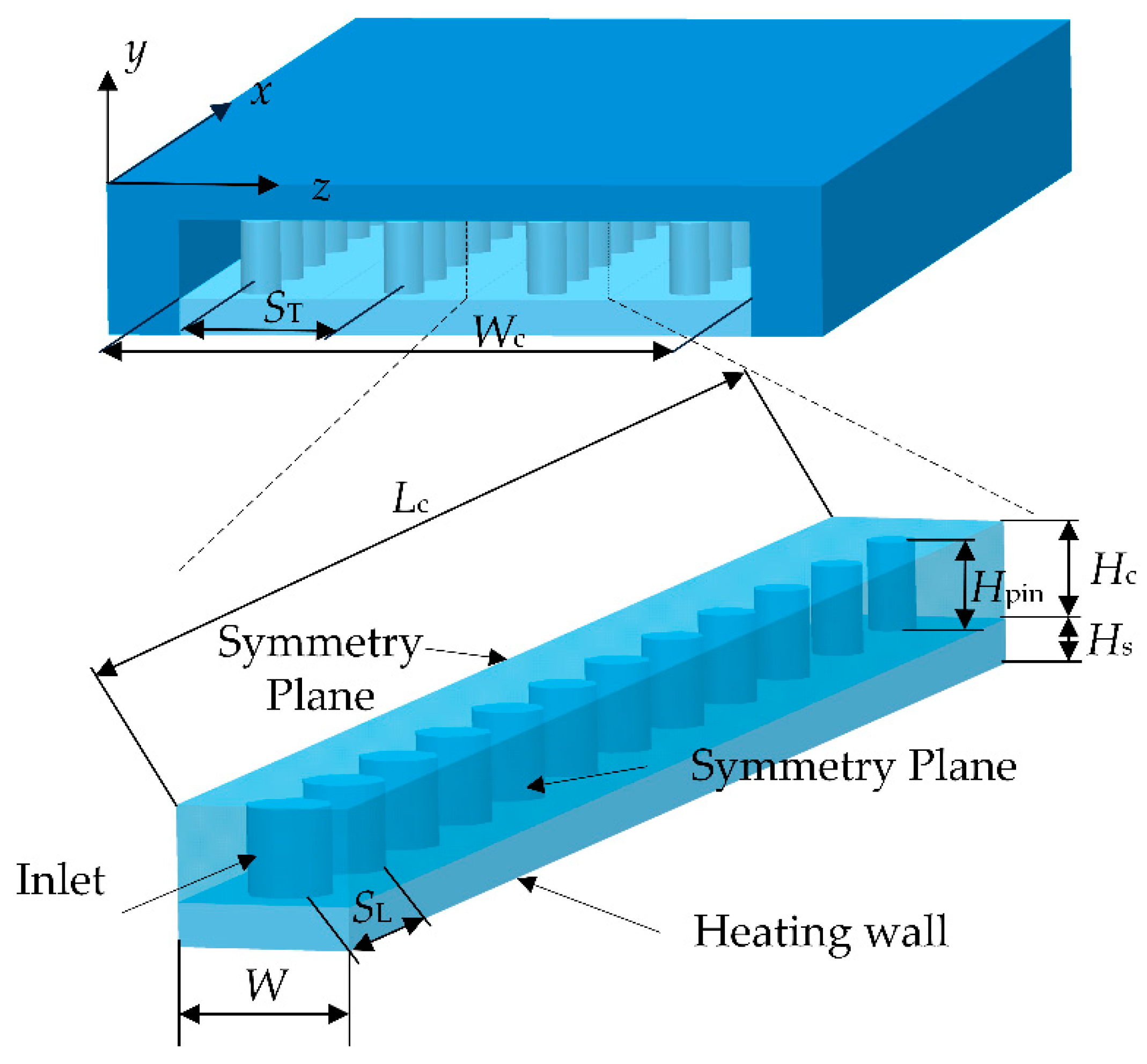
2.1. Computation Domain

A three-dimensional microreactor with NPFA was proposed to study the structural influence of the NPFA on the heat transfer of the microreactor. To reduce the calculation time, the symmetric channel was considered in this paper. Figure 1 is the schematic of the computing domain.
The NPFAs with five different pin diameter degressive gradients were used in this paper. The pin diameter degressive gradients were 1%, 2%, 4%, 6%, and 8%. Except for the pin diameter degressive gradient, the other structures of the five NPFAs were the same. The channel length Lc, the symmetric channel width W, the channel height Hc, the pin height Hpin, the transverse distances between the two adjacent pins ST, the longitudinal distances SL, and the solid thickness Hs were set up to be constant values. Based on the structure of symmetric channel, W = ST. Table 1 shows the detailed structural parameters of the symmetric channel in the NPFA.

2.2. Mathematical Modeling

The continuity equation, Navier–Stokes equation, and energy equation were adopted to model the flow and heat transfer process in the NPFA [37]. The fluid flow in the NPFA was assumed to be laminar [9,38], so the continuity equation and momentum and energy equations in the NPFA were as follows [9]:
ρ f u = 0 ,
ρ f ( u u ) = p + 2 ( μ f E ) 2 3   ( μ f u ) ,
ρ f c p ( u T f ) = ( k f T f ) - p ( u ) ,
k s 2 T s = 0 ,
where u, ρf, p, E, μf, cp, Tf, kf, ks, and Ts are the velocity vector in the NPFA, the density, the flow pressure, the stain-rate tensor, the fluid viscosity, the specific heat, the fluid temperature, the thermal conductivity of fluid, the thermal conductivity of solid, and the solid temperature, respectively.
The boundary conditions should be set, including inlet, outlet, adiabatic walls, and heated wall.
At the inlet,
u = u in ,   T f = T f , in ;
and at the outlet,
Pout = 0.
At the heated wall, a constant heat flux qcons was set to the following:
q = qcons.
All other boundaries except the two symmetry planes were set as adiabatic boundary conditions.

2.3. Numerical Methods

The governing differential equations described above were solved by the SIMPLE algorithm in the CFD program ANSYS-FLUENT 18. In this paper, the workstation was used for simulation. It has two Intel CPUs with 2.30 GHz frequency and 128 G memory. Each CPU has 24 cores. The governing equations were discrete with a two-order upstream scheme. The convergence criteria of the residuals for the variables were less than 10−5. The working fluid was air, assumed as the ideal gas. The solid material was alumina. The thermophysical properties used in this study are shown in detail in Table 2.
The grid independence was examined first. Three grid configurations were used with the numbers of cells as follows: 3.2 × 10⁵, 7.8 × 10⁵, and 3.0 × 10⁶. Table 3 shows their influences on the pressure drop ΔP and the fluid temperature at outlet Tout in the NPFA. The relative deviations of ΔP for the cells of grid 7.8 × 10⁵ and grid 3.0 × 10⁶ were small. The maximum value was only 1.68%. Moreover, the relative deviations of Tout for the cells of grid 7.8 × 10⁵ and grid 3.0 × 10⁶ were also small. The maximum value was 0.70%. Therefore, grid 7.8 × 10⁵ was chosen for the simulation after considering the calculation accuracy and time.
In this paper, two parameters, called the average Nusselt number Nu and the friction factor f, were used to estimate the thermal and hydrodynamic characteristics of the NPFA. The Nu was calculated using the following:
Nu = have Dpin/kf,
where have is the heat transfer coefficient, determined by the following:
have = q/(TwTf,ave),
where q is the input heat flux transferred to the fluid through the heating wall. Tw and Tf,ave are the wall temperature and average temperature of fluid, respectively. In this paper, Tf,ave was the average of the entrance and outlet temperatures.
The f is calculated by [39]
f = Δ P N L ( ρ f u max 2 2 ) ,
where umax is the maximum air velocity in the NPFA, expressed as
umax = Qf/Amin,
where Amin is expressed as
Amin = Wc HcNT Dpin Hpin = W HcDpin Hpin
where Wc is the channel width of microreactor (shown in Figure 1).

3. Results and Discussion
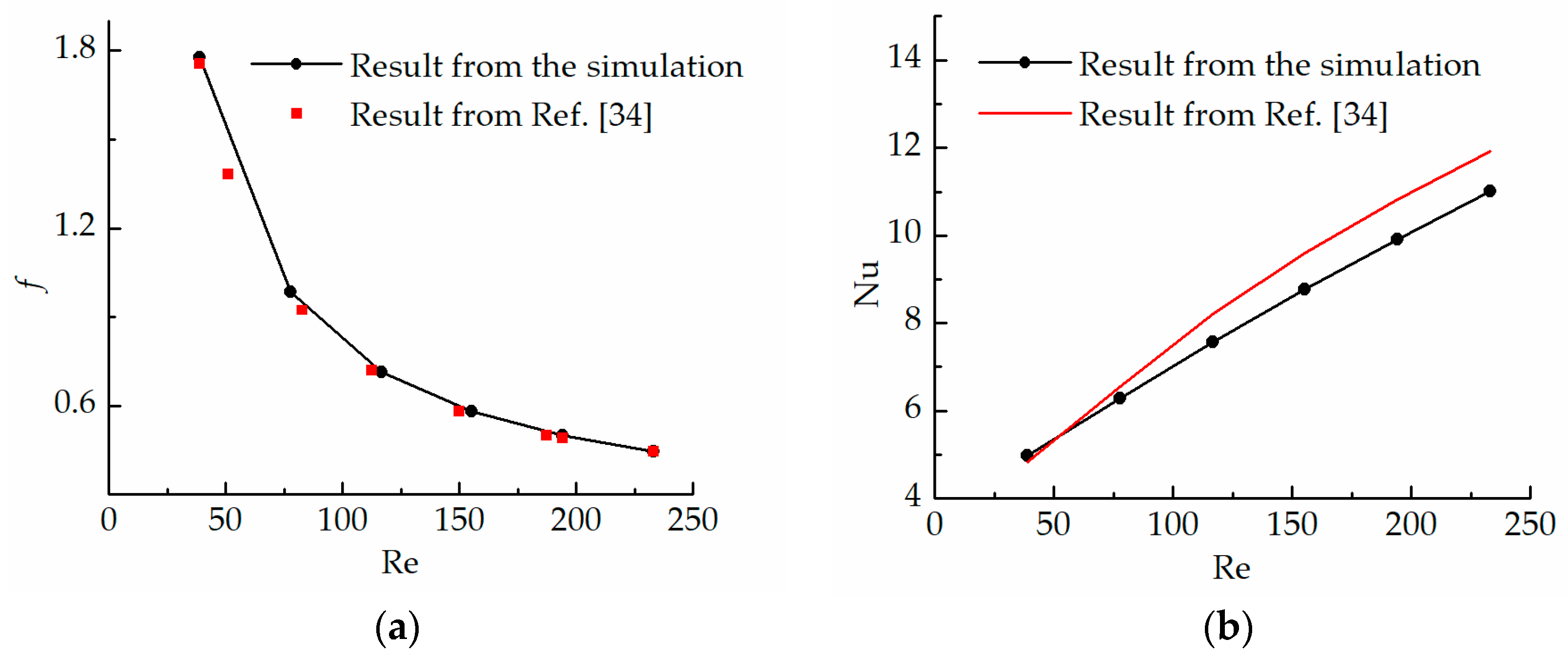
3.1. Validation

The effects of tip clearance on the Nu and f in the MPFAR were investigated via simulation, as described in [34]. The structure of the MPFAR for simulation in [34] was similar to that used in this paper. The differences between the model in this paper and that of [34] were the ST and SL. In this paper, ST = SL = 2 mm, while in [34], ST = SL = 1.8 mm. Thus, the simulation method used in this paper was used to calculate the f and Nu of the microreactor with Hc = 1.5 mm in [34]. Figure 2 shows comparisons of the simulated f and Nu from the simulation method used in this paper and the results from [34]. In Figure 2a, the simulated f via the simulation method used in this paper agrees well with that from [34]. The maximum relative error for f was less than 5%. In addition to comparing the simulated values obtained by this method with those obtained by [34], the simulated values of Nu are compared with the predictions from the heat transfer correlation proposed in [34], as shown in Figure 2b. From Figure 2b, the maximum relative error for Nu is small, less than 9%. This reveals that the simulation method accurately predicted the Nu and f of the pin-fin array proposed in [34], validating the feasibility of the numerical simulation for calculating Nu and f in NPFA.
In this paper, a symmetric channel, with left and right channel surfaces assigned to be symmetric planes, was used to reduce the calculation time, as shown in Figure 1. To validate the feasibility of this assumption, a comparison of the numerical results for the computation domain with a row of pins and two rows of pins was conducted. Figure 3 shows the pressure drop ΔP and outlet temperature Tout of the NPFA with calculation domains of one column of pins and two columns of pins with an inlet temperature Tin of 300 K.
As can be seen in Figure 3, the simulation results for ΔP and Tout for the computation domain with a row of pins agrees very well with those for the computation domain with two rows of pins. The largest relative deviation between them is less than 2%, which shows that the simplification of the symmetric channel was reasonable for investigating the thermal and hydrodynamic characteristics of the NPFA in the microreactor.

3.2. Influence of Pin Diameter Degressive Gradient

The friction coefficient f and Nu at various Reynolds numbers for various pin diameter degressive gradients of the NPFA were obtained by numerical simulation, as shown in Figure 4.
As can be seen in Figure 4, the Nu increased and f decreased for each diameter degressive gradient γ as the Reynolds number Re increased. These results are consistent with those in prior studies [30,34]. The non-uniform pin-fin array with a low diameter degressive gradient γ had a larger Nu, because it had more interface area with the air. When the Reynolds number was smaller, the air flowed slowly in the mini-channel and absorbed enough heat from the heated wall to decrease the temperature difference between the solid and fluid. Thus, the increment of the heat transfer area due to the decrease of γ had very little impact on the Nu, but when Re was larger, the influence of γ on the heat transfer became obvious. As can be observed in Figure 4, the Nusselt numbers for γ = 1% and 8% were 7.3 and 6.0, respectively, when the Re = 218. The relative difference between them was 17.8%, which revealed the important effects of pin diameter degressive gradients. However, the influence of γ on the f was opposite to that on the Nu. The effect of γ on the f was more obvious when the Re was small than that when the Re was large. As shown in Figure 4, the friction factors for γ = 1% and 8% were 2.8 and 1.8, respectively, when the Re = 40. The relative difference between them was 35.7%. The pin diameter decreased with the direction of the fluid flow when the pin diameter degressive gradient increased. The smaller pin dimeter decreased the fluid resistance, resulting in a smaller friction factor.

3.3. New Heat Transfer Correlation for NPFA

The heat transfer characteristic correlation in traditional theories is expressed by the exponential function relation between the Nu and Re and Pr.
Nu = c Re j Pr f , ave k ,
where Prf,ave is the dimensionless Prandtl number of air at Tf,ave, j and k represent the effect of the Re and Pr on the Nu, respectively (which are usually constants in Equation (13)), and c is a coefficient introduced to characterize the effects of the pin-fin array structure on the heat transfer.
Presently, there are many reports on the correlations of pin-fin arrays, but these correlations in previous studies were proposed for uniform pin-fin arrays and cannot be used for the NPFA. Thus, an improved heat transfer correlation was developed here. In the previous correlations from the literature, the effect of non-uniform structure was not considered. This paper introduces a non-uniform influencing factor (1 – γ)i to characterize the influence of the pin diameter degressive gradient for the NPFA in the basic correlation shown in Equation (13). Thus, a new heat transfer characteristic correlation of the NPFA was calculated from the following:
Nu = c ( 1 γ ) i Re j Pr f , ave k .
In Equation (13), the exponent k of the Prandtl number is often fixed as 1/3 [22,29]. Therefore, the Prandtl number is also assumed to be 1/3 in Equation (14). In Equation (14), i and j are indices of the pin diameter degressive gradient γ and Re, which are constants.
The above heat transfer correlation was fitted using the non-linear regression analysis method according to the data obtained via the numerical analysis to determine i, j, and c. The correlation of the non-uniform pin-fin array is as follows:
Nu = 0.716·Prf,ave(1/3)·(1 − γ)2.097·Re0.456,
where the ranges of Re and Prf,ave are from 40 to 218 and from 0.682 to 0.694, respectively.
In order to compare the predictions of Equation (15) with the present data obtained via simulation, the mean relative error was used. The formula of the MRENu is as follows:
MRE Nu = 1 M | Nu sim Nu pred | Nu sim × 100 % ,
where Nusim is the dimensionless Nusselt number obtained by numerical simulation and Nupred is the dimensionless Nusselt number obtained by the heat transfer correlation proposed in this paper.
The comparisons of the simulated Nu with the predictions of Equation (15) are shown in Figure 5. It can be observed in Figure 5 that the differences of the Nu between the simulation and the predictions of the correlation are small. The MRENu was calculated to be 2.4%, indicating that the heat transfer correlation proposed in this paper is reasonable to describe the Nu of the NPFA when the Re ranges from 40 to 218.

3.4. New Friction Factor Correlation for NPFA

The previous correlation for describing the flow characteristics of a pin-fin array in fluid mechanics theory is expressed by an exponential function of the Reynolds number:
f = cf Ren,
where cf is the dimensionless coefficient of the friction factor correlation, which characterizes the structural effect on the flow performance, and n is the exponent of the Re, which characterizes the influence of the Re on the friction factor f.
An improved correlation was also established in this study. Based on the friction factor correlation represented by Equation (17), we introduced (1-γ)m to consider the influence of the non-uniformity of the NPFA. Additionally, thermodynamic parameters such as viscosity change with the increase of the air temperature, so the relative kinematic viscosity υr, calculated as υout/υin considering the effect of the temperature change, is also added into the new friction factor correlation. Therefore, the friction factor correlation of the NPFA can be expressed as follows:
f = cf·υr·(1 − γ)m·Ren,
where the exponents m is constant, characterizing the influence of the variation of the pin diameter on the friction factor. The coefficient cf and the exponents m and n of the above correlation (Equation (18)) are determined using data from the simulation. Thus, the correlation of the NPFA is obtained as follows:
f = 12.337·υr·(1 − γ)6.936·Re(−0.686).
MREf is also used to compare the differences between the present simulated friction factor data and the predictions of Equation (19). The formula for calculating MREf can be expressed as follows:
MRE f = 1 M | f sim f pred | f sim × 100 % ,
where fsim is the dimensionless friction factor obtained by numerical simulation and fpred is the prediction obtained by the heat transfer correlation developed in this paper.
In Equation (19), the exponent of (1 – γ) is 6.9, which indicates that the pin diameter degressive gradient has a significant influence on the flow characteristics of the NPFA. Comparisons of the simulated f with the predictions of Equation (19) are shown in Figure 6. It can be observed that the friction factors obtained by the numerical simulation agree well with the predictions of Equation (19). The MREf was calculated to be 3.5%, indicating that the new correlation can be applied well to describe the flow characteristics of the NPFA when the Re ranges from 40 to 218.

4. Conclusions

Heat transfer and pressure drop characteristics play key roles in the efficiency of hydrogen-producing reactors. In this study, the influence of the pin diameter degressive gradient of the non-uniform pin-fin array on the heat transfer and pressure drop characteristics at a low Re was studied via numerical simulation. The results are as follows:
(1)
The Nu and f at a low Re were sensitive to the pin diameter degressive gradient. With an increase of the pin diameter degressive gradient, the f and Nu decreased.
(2)
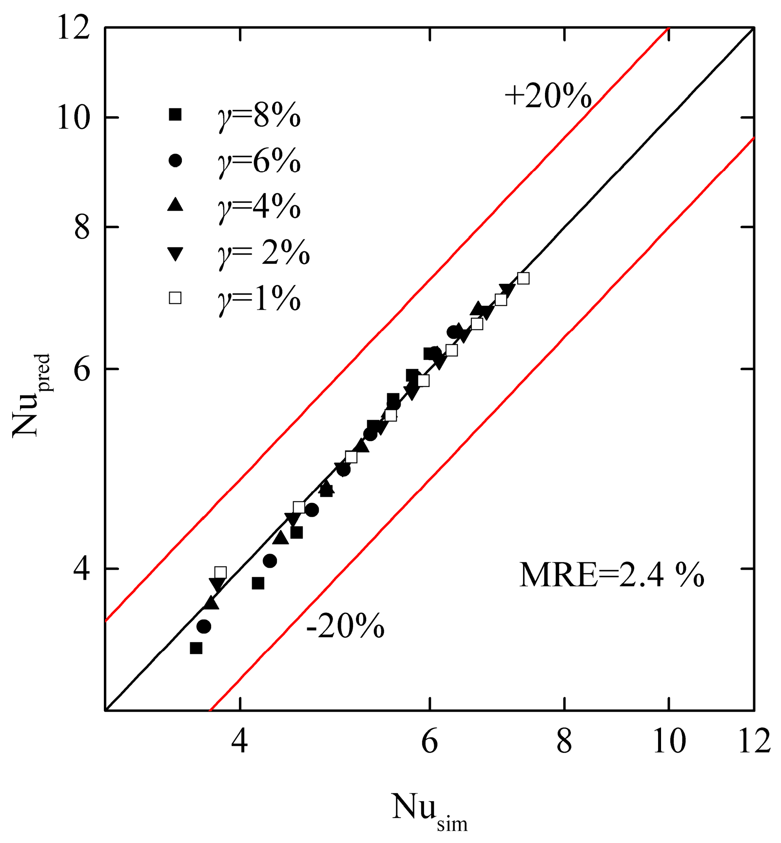
To guide the optimization of the pin diameter degressive gradient for the NPFA, a new heat transfer correlation was developed in this paper. The exponent of (1 – γ) for the Nusselt number was 2.1, indicating that the pin diameter degressive gradient had an impact on the heat transfer characteristics of the NPFA. MRENu was calculated to be 2.4%, indicating that the new heat transfer correlation adequately predicted the Nusselt number of the NPFA with various pin diameter degressive gradients.
(3)
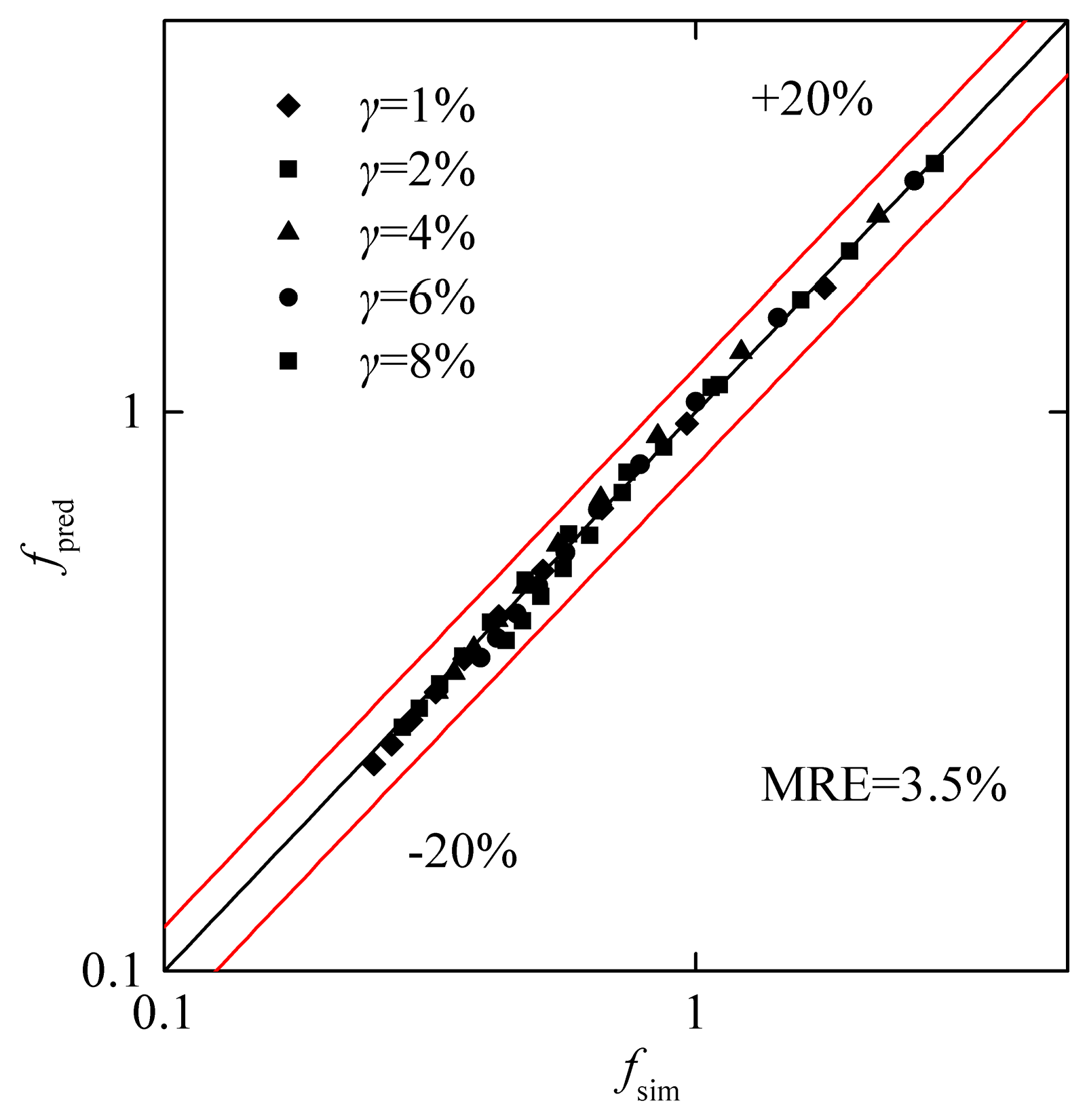
A new friction factor correlation was developed in this paper to account for the effect of the pin diameter degressive gradient. The exponent of (1 – γ) for the friction factor was 6.9, indicating the significant influence of the pin diameter degressive gradient on the pressure drop characteristics of the NPFA. MREf was calculated to be 3.5%, showing the feasibility of the improved friction factor correlation to predict the f of the NPFA with various pin diameter degressive gradients.
The research provides a theoretical approach to optimize the structural parameters of the NPFAR for hydrogen production. It can be used to design the NPFA under low Reynolds number conditions and further optimize the structure of the NPFA. The effects of the other structural parameters of the NPFA on the heat transfer will be determined in future studies.

Author Contributions

M.Q. conceived and edited the manuscript, J.L. carried out the validation. M.Q. and C.Y. carried out the numerical simulation. Z.X. and X.H. supervized the study and analyzed the data. All the authors reviewed the manuscript.

Funding

This research was funded by [the Zhejiang Provincial Public Projects of China] grant number [LGG18E050022], [the National Natural Science Foundation of China], grant numbers [U1609205 and 51605443]; [Zhejiang Key R&D Program] grant numbers [2019C01027 and 2018C01027]; and [the Young Researchers Foundation of Zhejiang Provincial Top Key Academic Discipline of Mechanical Engineering of Zhejiang Sci-tech University] grant number [ZSTUME02B13].

Conflicts of Interest

The authors declare no conflicts of interest.

Nomenclature

Aminthe minimum transverse section area of the channel: m2
cpspecific heat, J/(kg K)
Dpindiameter of pin, mm
ffriction factor
haveheat transfer coefficient, W/(m2 K)
Hcchannel height, mm
Hpinpin height, mm
Hssolid thickness, mm
kfthermal conductivity of fluid, W/(m K)
ksthermal conductivity of solid, W/(m K)
Lcchannel length, mm
Mthe number of data points
NLthe number of pin-fin along the lengthwise direction
NTthe number of pin-fin along the transverse direction
Nuaverage Nusselt number
pflow pressure, Pa
PrPrandtl number
qheat flux, W/m2
Qfinlet flow rate, m3/s
ReReynolds number
SLlongitudinal center distance between two pins, mm
STtransverse center distance between two pins, mm
Tfthe fluid temperature, K
Tsthe solid temperature, K
Twwall temperature, K
Wthe symmetric channel width, mm
Wcchannel width of microreactor, mm
Greek symbols
υrrelative flow dynamic viscosity, υout/υin
γpin diameter degressive gradient
μfflow viscosity, Pa s
ρffluid density, kg/m3

References

  1. Peighambardoust, S.J.; Rowshanzamir, S.; Amjadi, M. Review of the proton exchange membranes for fuel cell applications. Int. J. Hydrogen Energy 2010, 35, 9349–9384. [Google Scholar] [CrossRef]
  2. AbouOmar, M.S.; Zhang, H.J.; Su, Y.X. Fractional order fuzzy pid control of automotive pem fuel cell air feed system using neural network optimization algorithm. Energies 2019, 12, 1435. [Google Scholar] [CrossRef]
  3. Yu, L.J.; Ren, G.P.; Qin, M.J.; Jiang, X.M. Simulation of performance influencing factors of proton exchange membrane fuel cells in different flow modes. Eng. Appl. Comput. Fluid Mech. 2008, 2, 344–353. [Google Scholar] [CrossRef]
  4. Holladay, J.D.; Hu, J.; King, D.L.; Wang, Y. An overview of hydrogen production technologies. Catal. Today 2009, 139, 244–260. [Google Scholar] [CrossRef]
  5. Navarro, R.M.; Sanchez-Sanchez, M.C.; Alvarez-Galvan, M.C.; Valle, F.D.; Fierro, J.L.G. Hydrogen production from renewable sources: Biomass and photocatalytic opportunities. Energy Environ. Sci. 2009, 2, 35–54. [Google Scholar] [CrossRef]
  6. Aartun, I.; Silberova, B.; Venvik, H.; Pfeifer, P.; Gorke, O.; Schubert, K.; Holmen, A. Hydrogen production from propane in rh-impregnated metallic microchannel reactors and alumina foams. Catal. Today 2005, 105, 469–478. [Google Scholar] [CrossRef]
  7. Resnik, D.; Hocevar, S.; Batista, J.; Vrtacnik, D.; Mozek, M.; Amon, S. Si based methanol catalytic micro combustor for integrated steam reformer applications. Sens. Actuators A Phys. 2012, 180, 127–136. [Google Scholar] [CrossRef]
  8. Sohn, J.M.; Chang Byun, Y.; Yeon Cho, J.; Choe, J.; Ho Song, K. Development of the integrated methanol fuel processor using micro-channel patterned devices and its performance for steam reforming of methanol. Int. J. Hydrogen Energy 2007, 32, 5103–5108. [Google Scholar] [CrossRef]
  9. Mei, D.Q.; Liang, L.W.; Qian, M.; Feng, Y.B. A performance study of methanol steam reforming in an a-type microchannel reactor. Int. J. Hydrogen Energy 2014, 39, 17690–17701. [Google Scholar] [CrossRef]
  10. Jang, J.Y.; Cheng, C.H.; Huang, Y.X.; Lee, C.I.; Leu, C.H. Optimal design of parallel channel patterns in a micro methanol steam reformer. Int. J. Hydrogen Energy 2012, 37, 16974–16985. [Google Scholar] [CrossRef]
  11. Zhou, W.; Deng, W.; Lu, L.; Zhang, J.; Qin, L.; Ma, S.; Tang, Y. Laser micro-milling of microchannel on copper sheet as catalyst support used in microreactor for hydrogen production. Int. J. Hydrogen Energy 2014, 39, 4884–4894. [Google Scholar] [CrossRef]
  12. Hsueh, C.Y.; Chu, H.S.; Yan, W.M.; Chen, C.H. Transport phenomena and performance of a plate methanol steam micro-reformer with serpentine flow field design. Appl. Energy 2010, 87, 3137–3147. [Google Scholar] [CrossRef]
  13. Yao, F.; Chen, Y.; Peterson, G.P. Hydrogen production by methanol steam reforming in a disc microreactor with tree-shaped flow architectures. Int. J. Heat Mass Transf. 2013, 64, 418–425. [Google Scholar] [CrossRef]
  14. Pan, M.Q.; Tang, Y.; Wei, X.L.; Jiang, X. Oriented linear cutting fiber sintered felt as an innovative catalyst support for methanol steam reforming. Int. J. Hydrogen Energy 2011, 36, 7066–7073. [Google Scholar] [CrossRef]
  15. Pan, M.Q.; Wei, X.L.; Tang, Y. Factors influencing methanol steam reforming inside the oriented linear copper fiber sintered felt. Int. J. Hydrogen Energy 2012, 37, 11157–11166. [Google Scholar] [CrossRef]
  16. Mei, D.Q.; Qian, M.; Liu, B.H.; Jin, B.; Yao, Z.H.; Chen, Z.C. A micro-reactor with micro-pin-fin arrays for hydrogen production via methanol steam reforming. J. Power Sources 2012, 205, 367–376. [Google Scholar] [CrossRef]
  17. Mei, D.Q.; Qian, M.; Yao, Z.H.; Liu, B.H.; Lou, X.Y.; Chen, Z.C. Effects of structural parameters on the performance of a micro-reactor with micro-pin-fin arrays (MPFAR) for hydrogen production. Int. J. Hydrogen Energy 2012, 37, 17817–17827. [Google Scholar] [CrossRef]
  18. Hao, Y.Z.; Du, X.Z.; Yang, L.J.; Shen, Y.Q.; Yang, Y.P. Numerical simulation of configuration and catalyst-layer effects on micro-channel steam reforming of methanol. Int. J. Hydrogen Energy 2011, 36, 15611–15621. [Google Scholar] [CrossRef]
  19. Zhou, W.; Wang, Q.; Li, J.; Tang, Y.; Huang, Z.; Zhang, J.; Lu, Q. Hydrogen production from methanol steam reforming using porous copper fiber sintered felt with gradient porosity. Int. J. Hydrogen Energy 2015, 40, 244–255. [Google Scholar] [CrossRef]
  20. Qian, M.; Mei, D.Q.; Yi, Z.D.Y.; Feng, Y.B.; Chen, Z.C. Fluid flow and heat transfer performance in a micro-reactor with non-uniform micro-pin-fin arrays for hydrogen production at low Reynolds number. Int. J. Hydrogen Energy 2017, 42, 553–561. [Google Scholar] [CrossRef]
  21. Short, B.E.; Price, D.C.; Raad, P.E. Performance of pin fin cast aluminum coldwalls, part 1: Friction factor correlations. J. Thermophys. Heat Transf. 2002, 16, 389–396. [Google Scholar] [CrossRef]
  22. Short, B.E.; Raad, P.E.; Price, D.C. Performance of pin fin cast aluminum coldwalls, part 2: Colburn j-factor correlations. J. Thermophys. Heat Transf. 2002, 16, 397–403. [Google Scholar] [CrossRef]
  23. Armstrong, J.; Winstanley, D. A review of staggered array pin fin heat transfer for turbine cooling applications. J. Turbomach. 1988, 110, 94–103. [Google Scholar] [CrossRef]
  24. Hwang, T.H.; Yao, S.C. Crossflow heat transfer in tube bundles at low reynolds numbers. J. Heat Transf. 1986, 108, 697–700. [Google Scholar] [CrossRef]
  25. Zukauskas, A. Heat transfer from tubes in crossflow. Adv. Heat Transf. 1972, 8, 93–160. [Google Scholar]
  26. Huang, L.; Li, Q.; Zhai, H. Experimental study of heat transfer performance of a tube with different shaped pin fins. Appl. Therm. Eng. 2018, 129, 1325–1332. [Google Scholar] [CrossRef]
  27. Chyu, M. Heat transfer and pressure drop for short pin-fin arrays with pin-endwall fillet. J. Heat Transf. 1990, 112, 926–932. [Google Scholar] [CrossRef]
  28. Hwang, J.J.; Lai, D.Y.; Tsia, Y.P. Heat transfer and pressure drop in pin-fin trapezoidal ducts. J. Turbomach. 1999, 121, 264–271. [Google Scholar] [CrossRef]
  29. Qu, W.L.; Siu-Ho, A. Liquid single-phase flow in an array of micro-pin-fins—Part I: Heat transfer characteristics. J. Heat Transf. 2008, 130. [Google Scholar] [CrossRef]
  30. Qu, W.L.; Siu-Ho, A. Liquid single-phase flow in an array of micro-pin-fins—Part II: Pressure drop characteristics. J. Heat Transf. 2008, 130. [Google Scholar] [CrossRef]
  31. Mita, J.; Qu, W. Pressure drop of water flow across a micro-pin–fin array part 1: Isothermal liquid single-phase flow. Int. J. Heat Mass Tranf. 2015, 89, 1073–1082. [Google Scholar] [CrossRef]
  32. Moores, K.A.; Joshi, Y.K. Effect of tip clearance on the thermal and hydrodynamic performance of a shrouded pin fin array. J. Heat Transf. 2003, 125, 999–1006. [Google Scholar] [CrossRef]
  33. Moores, K.A.; Kim, J.; Joshi, Y.K. Heat transfer and fluid flow in shrouded pin fin arrays with and without tip clearance. Int. J. Heat Mass Transf. 2009, 52, 5978–5989. [Google Scholar] [CrossRef]
  34. Mei, D.Q.; Lou, X.Y.; Qian, M.; Yao, Z.H.; Liang, L.W.; Chen, Z.C. Effect of tip clearance on the heat transfer and pressure drop performance in the micro-reactor with micro-pin-fin arrays at low reynolds number. Int. J. Heat Mass Transf. 2014, 70, 709–718. [Google Scholar] [CrossRef]
  35. Tullius, J.F.; Tullius, T.K.; Bayazitoglu, Y. Optimization of short micro pin fins in minichannels. Int. J. Heat Mass Transf. 2012, 55, 3921–3932. [Google Scholar] [CrossRef]
  36. Arjun, K.S.; Kumar, R. Optimization of micro pin-fin heat sink with staggered arrangement. Therm. Sci. 2018, 22, 2919–2931. [Google Scholar] [CrossRef]
  37. Xia, G.D.; Jiang, J.; Wang, J.; Zhai, Y.L.; Ma, D.D. Effects of different geometric structures on fluid flow and heat transfer performance in microchannel heat sinks. Int. J. Heat Mass Transf. 2015, 80, 439–447. [Google Scholar] [CrossRef]
  38. Smith, F.T. A structure for laminar-flow past a bluff body at high reynolds-number. J. Fluid Mech. 1985, 155, 175–191. [Google Scholar] [CrossRef]
  39. Prasher, R.S.; Dirner, J.; Chang, J.Y.; Myers, A.; Chau, D.; He, D.M.; Prstic, S. Nusselt number and friction factor of staggered arrays of low aspect ratio micropin-fins under cross flow for water as fluid. J. Heat Transf. 2007, 129, 141–153. [Google Scholar] [CrossRef]
Figure 1. Schematic diagram of the pin-fin array.
Energies 12 02702 g001
Figure 2. Numerical validation of the simulation method with the results from [34]: (a) f versus the Reynolds number Re; (b) Nu versus Re.
Energies 12 02702 g002
Figure 3. The variation in the pressure drop and outlet temperature of the non-uniform pin-fin array (NPFA) over the Re for the calculation domain with one row of pins and two rows of pins under an inlet temperature of 300 K.
Energies 12 02702 g003
Figure 4. Variations in the (a) f and (b) Nu with the Re at various pin diameter degressive gradients for Tin = 300 K and q = 10,000 W/m2.
Energies 12 02702 g004
Figure 5. Comparison of the simulated Nu with the predictions of Equation (15) for the NPFA.
Energies 12 02702 g005
Figure 6. Comparison of the simulated f with the predictions of Equation (19) for the NPFA.
Energies 12 02702 g006
Table 1. Structural parameters of the non-uniform pin-fin array for hydrogen production.
Change Rate of Pin Diameter γ, %1, 2, 4, 6, 8
Diameter for the first pin Dpin, mm1
Pin height Hpin, mm1
Channel length Lc, mm29
Symmetric channel width W, mm2
Channel height Hc, mm1.1
Hc/Hpin,1.1
Hs, mm0.5
SL, mm2
ST, mm2
Pin-fin number along the lengthwise direction NL12
Table 2. Thermophysical properties of the fluid.
Tair, Kcp, J/(kg K)kf × 102, W/(m K)μf × 106, Pa s
293.1510052.5918.1
313.1510052.7619.1
333.1510052.920.1
353.1510093.0521.1
373.1510093.2121.9
413.1510133.4923.7
453.1510223.7825.3
523.1510384.2727.4
623.1510594.9131.4
Table 3. The pressure drop and fluid temperature at the outlet with various Reynolds numbers (Re) in the NPFA for different grids.
ReΔP, PaTout, K
3.2 × 1057.8 × 1053.0 × 1063.2 × 1057.8 × 1053.0 × 106
39.816.8416.6016.66578.25574.56570.57
79.625.4926.6326.19443.14442.35441.39
119.336.6737.6037.59395.97395.63395.20
159.149.6250.9250.86372.18371.96371.72
199.064.5764.7465.24357.81357.62357.45

