Article

Design and Validation of Ultra-Fast Charging Infrastructures Based on Supercapacitors for Urban Public Transportation Applications

by
Fernando Ortenzi
1,*,
Manlio Pasquali
1,
Pier Paolo Prosini
1,
Alessandro Lidozzi
2 and
Marco Di Benedetto
2
1
ENEA - Italian Agency for New Technologies, Energy and Sustainable Economic Development, 00123 Rome, Italy
2
ROMA TRE University, Department of Engineering, 00146 Rome, Italy
*
Author to whom correspondence should be addressed.
Energies 2019, 12(12), 2348; https://doi.org/10.3390/en12122348
Submission received: 20 May 2019 / Revised: 13 June 2019 / Accepted: 17 June 2019 / Published: 19 June 2019
(This article belongs to the Special Issue Advances in Supercapacitor Technology and Applications)

Abstract

:
The last few decades have seen a significant increase in the number of electric vehicles (EVs) for private and public transportation around the world. This has resulted in high power demands on the electrical grid, especially when fast and ultra-fast or flash (at the bus-stop) charging are required. Consequently, a ground storage should be used in order to mitigate the peak power request period. This paper deals with an innovative and simple fast charging infrastructure based on supercapacitors, used to charge the energy storage system on board electric buses. According to the charging level of the electric bus, the proposed fast charging system is able to provide the maximum power of 180 kW without exceeding 30 s and without using DC–DC converters. In order to limit the maximum charging current, the electric bus is charged in three steps through three different connectors placed between the supercapacitors on board the bus and the fast charging system. The fast charging system has been carefully designed, taking into account several system parameters, such as charging time, maximum current, and voltage. Experimental tests have been performed on a fast charging station prototype to validate the theoretical analysis and functionality of the proposed architecture.

1. Introduction

The electric vehicles (EVs) in public transportation could be the keystone to limit a city’s traffic problem, noise level, and pollution within urban complexes with high population density [1,2]. In fact, having electric public vehicles in the city center will have a large positive environmental effect on both noise and pollution. According to the many advantages provided by EVs, more and more cities have been replacing their public vehicles with electric vehicles [3,4,5,6,7,8]. In [7], a cost-benefit method was employed for the scheduling of an electric city bus fleet on a single route. Three different charging infrastructure scenarios were considered. In the first scenario, only one charging station was used. The second scenario considered two charging stations that were located at the same terminus. In the third scenario, two charging stations were located at opposite terminuses. The first scenario is the cheaper solution compared to the others. The second solution is more suitable in terms of energy demand and traffic conditions. However, the electric vehicles, such as electric buses, are limited by the onboard storage system and the long charging times, which depends on the charging infrastructure. There are several different methods to charge the electric buses [8,9].
  • Overnight charging method. In this case, the electric buses are equipped with a huge energy storage system in order to satisfy the bus routes during the day. The large storage system (i.e., for a 12 m bus there are about 350 kWh of lithium batteries) must be recharged during the night (in about 6 h).
  • Route charging method. In this method, the buses are charging in the bus-station during each break at the end of the routes. The charging time takes only 10–15 min. Compared to the previous method, the energy storage system is significantly reduced (i.e., for a 12 m bus there are about 40–60 kWh of lithium batteries), whereas the charging infrastructure is more stressed than the overnight charger due to the higher power requests. Thus, in this case, the advantage is the smaller energy storage system onboard the buses, leading to less costs.
  • Flash charging method. In this case, the electric bus recharges at bus stops in just a few seconds. In fact, the charging time takes only 20–30 s (when the passengers are getting on the bus). Then, each time the buses come to the final stop throughout the day, it quickly recharges. The energy storage system on board the bus is smaller than in previous cases (i.e., for a 12 m bus there are about 1–2 kWh of lithium batteries). Since the charge/discharge are carried out at high power, the energy storage system is composed of supercapacitors instead of batteries. Consequently, the supercapacitors are used to realize charging infrastructure. Using this method, the costs are drastically reduced due to the smaller energy storage system on board the bus compared to the previous methods.
Compared to the slow charging stations, the main advantages of the fast charging stations are an extended range autonomy and a smaller storage system. Unfortunately, the connection of the unexpected loads, such as an energy storage system, to the electrical grid may cause unwanted effects on the grid due to the great power demands for short times. For instance, the Hess-ABB Tosa (Trolleybus Optimisation System Alimentation), an 18 m bus fitted out by ABB with an optimized complete traction chain, is composed by 40 kWh energy-storage units and an automatic energy transfer system at bus-stops. This electric bus is charged two times on the 18 km route. The first charging point, called Palexpo Flash Station, is equipped with a 400 kW power supply unit and the charging time is only 15 s, whereas the second charging point is composed by a 200 kW power supply unit, and the charging time is 3–4 min. These storage systems inevitably require expensive components with a large effect on investment costs. Performance and cost optimization of charging stations and electric storage systems pass through technology solutions able to integrate devices with different functions.
In [1], the evaluating methodology of power-quality field measurements of an electric bus charging station in Taiwan was proposed. In this case, the charging station under study had 11 charging poles, including two fast charging and nine slow charging poles. Experimental measurements of voltage flickers, harmonic distortion, including electrical power measurements, and three phase voltages were performed. In [2], a control structure for the DC charging station was proposed. The charging station makes use of the frontend AC–DC converter, including the power grid filters, and backend DC–DC converter connected via DC link capacitor. The DC–DC converter is controlled through the P-controller, whereas the AC–DC converter is controlled using the PI (Proportional-Integral) controller, where the input error is provided by the difference between the measured grid voltage and reference voltages. The charging station proposed in [5] is equipped with a modular multilevel converter (MMC) and the control structure is based on finite control set-model predictive control.
Such charging processes can be realized using the supercapacitors. The advantages of supercapacitors can be highlighted in three different characteristics [10]: (1) high specific power—supercapacitors can be totally discharged and charged in the order of seconds; (2) long life, to the order of 106 cycles; (3) low specific energy.
The use of supercapacitors in both hybrid vehicles and hybrid storage configurations, including microcars or forklifts, has been discussed in different papers [11,12,13]. In an electric microcar tested on a dynamometer chassis running the urban part of the previous type approval procedure driving cycle (ECE15) [11], the addition of supercapacitors to the battery storage brought a reduction of the maximum current from lead-acid batteries and then advantages in terms of vehicle range (more than 50%) and battery life (more than double). The same results have been obtained also on a forklift [12]. Such advantages (in terms of range) have not been obtained if the vehicle is equipped with lithium-ion batteries due to their lower internal resistance [13].
In this paper, a flash charging infrastructure, a three-year project called “Ricerca di Sistema Elettrico”, has been designed, evaluated in terms of investment costs [14,15], and tested using a reduced scale model prototype [16]. Such charging infrastructure needs to be equipped with a storage system based on supercapacitors due to the high-power transfer. The realized electric bus has a hybrid storage system composed of lead acid batteries for the auxiliaries and backup, as well as the supercapacitors for the traction. Furthermore, the proposed system presents an innovative concept, where the charging is directly performed between two supercapacitors without use of the converter: the first one placed in the charging station and the second one placed on board the electric bus. To limit the charging current, an inductor is connected between the supercapacitors and the charge is made in three different configurations by changing the connection of the supercapacitors in the charging station. The advantages of the present configuration are that the charging station is simpler and does not have any expensive devices like a converter; the only components used are contactors and an inductance, cheaper than a DC–DC converter designed for such a purpose.
The paper is organized in six parts. The background of the charging station in the electric buses is discussed in Section 1. The electric bus details (Tecnobus Gulliver U500), equipped with the pantograph and the hybrid storage system, adapted to be compliant with the present charging system, is explained in Section 2. The charging architecture and the charging control strategy is discussed in Section 3, while experimental results are presented in Section 4. Section 5 investigates the possible structure and the management of a complex charging network for public transport. Finally, Section 6 gives the conclusions.

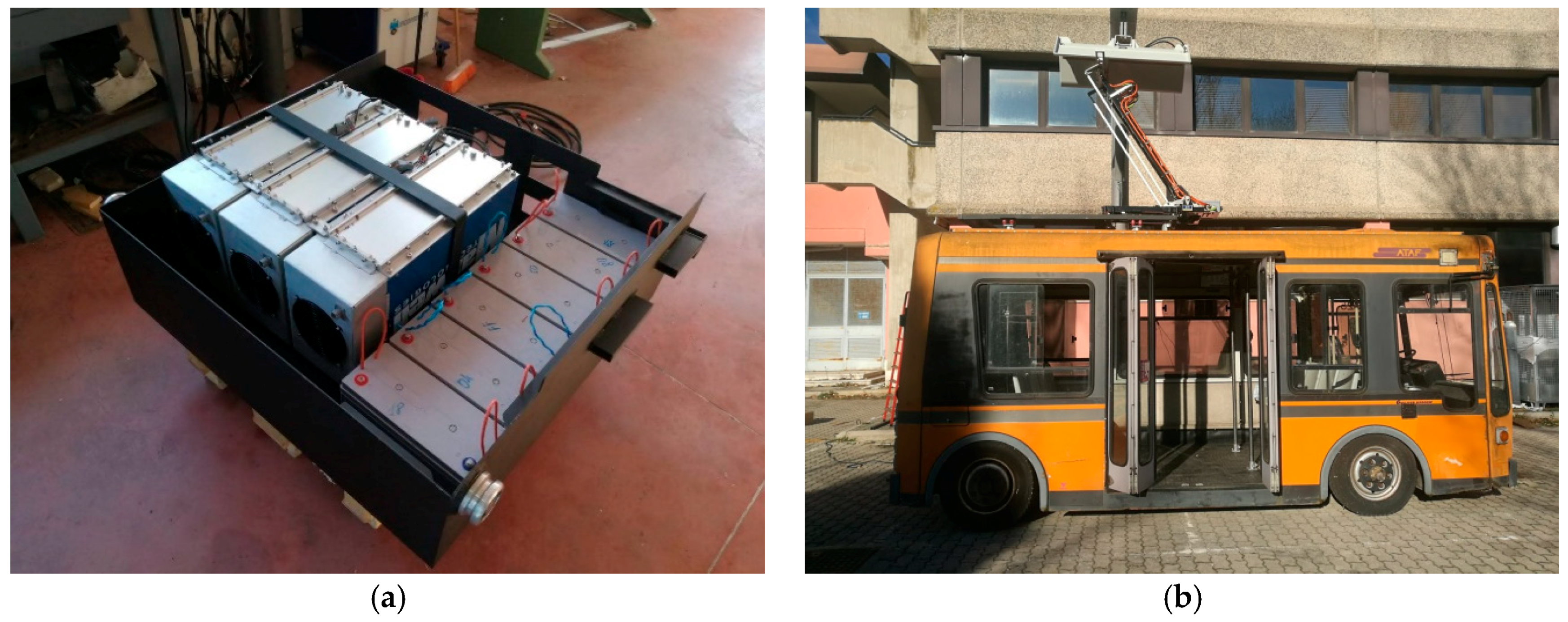
2. The Pantograph Equipped Vehicle

The vehicle used to test the flash charge infrastructure was a minibus, Tecnobus Gulliver U500, also used for previous fast charge experimentation [17,18]. The specifications of the minibus are reported in Table 1.
This vehicle was originally equipped with lead acid batteries. The previous experimental results, carried out at the ENEA (Italian Agency for New Technologies, Energy and Sustainable Economic Development) Casaccia Research Center, were also obtained using the LFP (lithium iron phosphate ) batteries [18].
The energy storage system on board the bus was specifically designed in order to use the flash charging method. The energy storage was composed by a hybrid system, where 8.6 kWh lead acid batteries (72 V/120 Ah) were used together with three Maxwell supercapacitor modules (125 V, 63 F) connected in series, as shown in Figure 1a. The lead acid batteries were used for both the auxiliaries and as a backup battery, when the supercapacitors were totally discharged during the route of the bus. Furthermore, the batteries helped to partially discharge the supercapacitors, when their voltage was too high to be charged. The nominal energy of the supercapacitors was 410 Wh; nevertheless, since the supercapacitors worked at half their nominal voltage, only 75% of the supercapacitors’ nominal energy was used. The description of the architecture on board the bus is explained in more detail in [19]. Figure 1b shows the pantograph installed on the bus. The pantograph was a fast charging device manufactured by Schunk with the following characteristics:
  • Maximum operating voltage: 1000 V;
  • Continuous charging current: 150 A (6 h);
  • Maximum charging current: 1000 A (15 min);
  • Service life: 100,000 cycles.

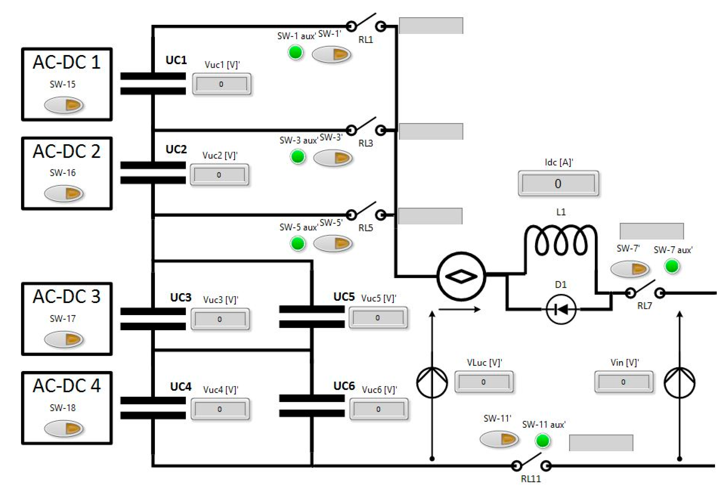
3. Charging Architecture

The main characteristics of the flash charging method proposed in this paper are the following:
(1)
The charging time at every bus-stop must be less than the pick-up and drop-off times of the passengers. The acceptable charging time is fixed at 30 s;
(2)
The charging station supercapacitors must be rapidly charged. A maximum charging time is set at 3 min;
(3)
The charging station must charge the electric bus even if the bus storage system has a different voltage from the designed value. The bus energy consumption is not constant during its route, depending on traffic and passenger load. Consequently, the charging station must be able to charge the bus independently of the state of the charge of the onboard supercapacitors;
(4)
A ground storage is required to reduce the peak power demanded of the power grid.
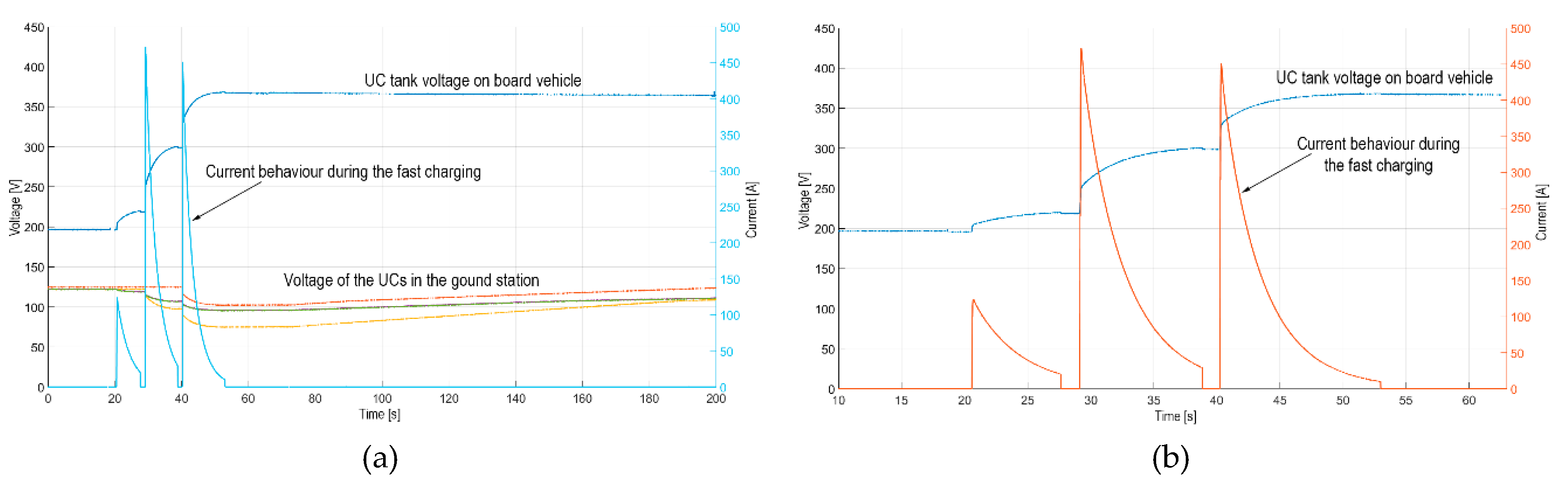
In [14,15,16] the charging station was designed and tested in a reduced scale prototype. In that case, the power levels were not taken into account and the electric scheme of the charging station was created to optimize the simulation model. Such a system was composed by six ultra-capacitors in the ground charging station and three onboard the vehicle, each one of 16 V and 250 F. Starting from this analysis, in this paper a real scale protype was built. In this paper, the proposed charging station was built with the architecture explained below.
The block scheme of the proposed charging station is depicted in Figure 2. Five contactors were used to operate the charging process. The charging was made in three steps: (1) four modules, connected two in series and two in parallel (2s2p), were used to charge the vehicle; (2) an extra module was added in series to the others; and (3) a sixth module was connected in series to the others.
In the first step, the contactors RL5, RL11, and RL7 were closed to allow the four-supercapacitor module to transfer energy from the charging station to the onboard supercapacitors. When the charging transfer was almost complete (or the current fell below 20 A), the contactor RL5 was opened, while the contactor RL3 was closed to start the second step. When the second step was finished, the closure of the RL1 started the third step. Finally, four AC–DC converters with 2 kW rated power were used to charge the supercapacitors after the energy transfer process. The maximum charging current was limited, using the inductor and resistor with the parameters listed in Table 2. The inductor is shown in Figure 3. The supercapacitor configuration together with the inductance is an efficient strategy to manage the flash charge in a cheap way. The reason for the use of three recharge steps instead of one is related to the possibility of reducing the maximum recharge current and optimizing the energy transfer.

4. Results

Different tests were carried out in order to validate the design of the proposed charging station.
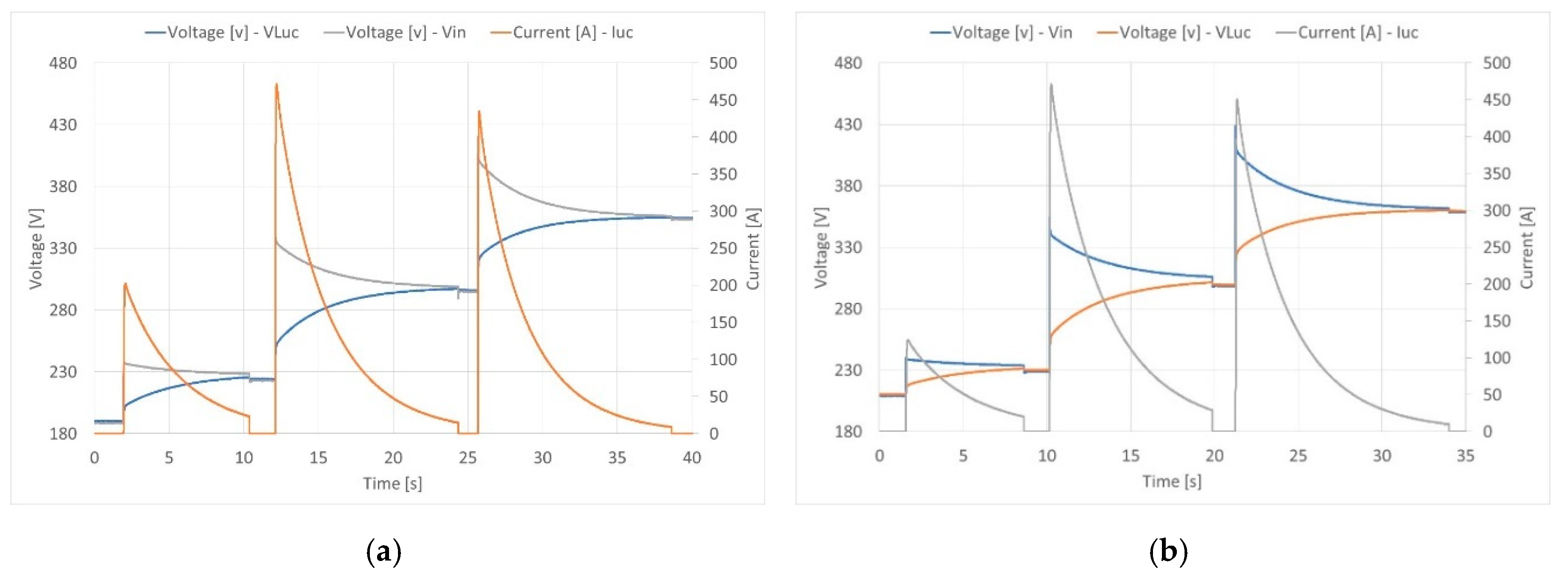
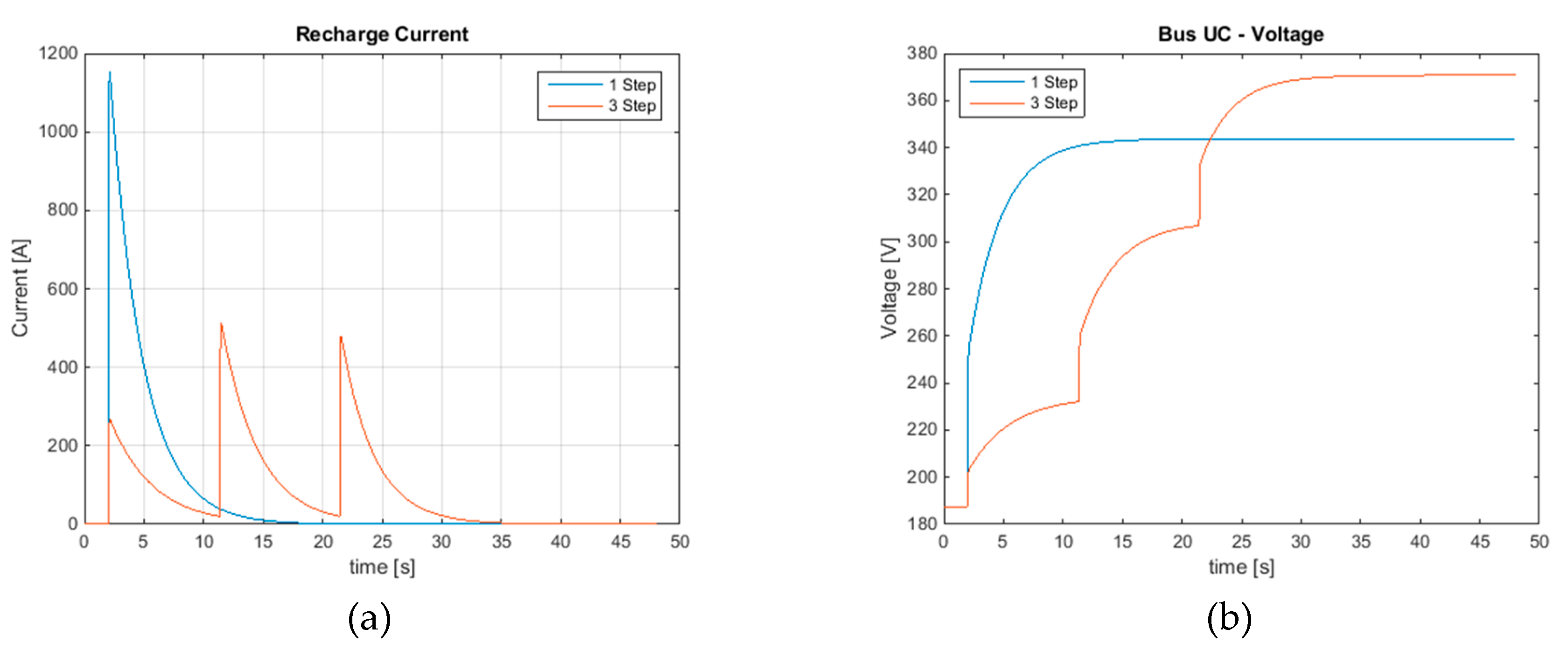
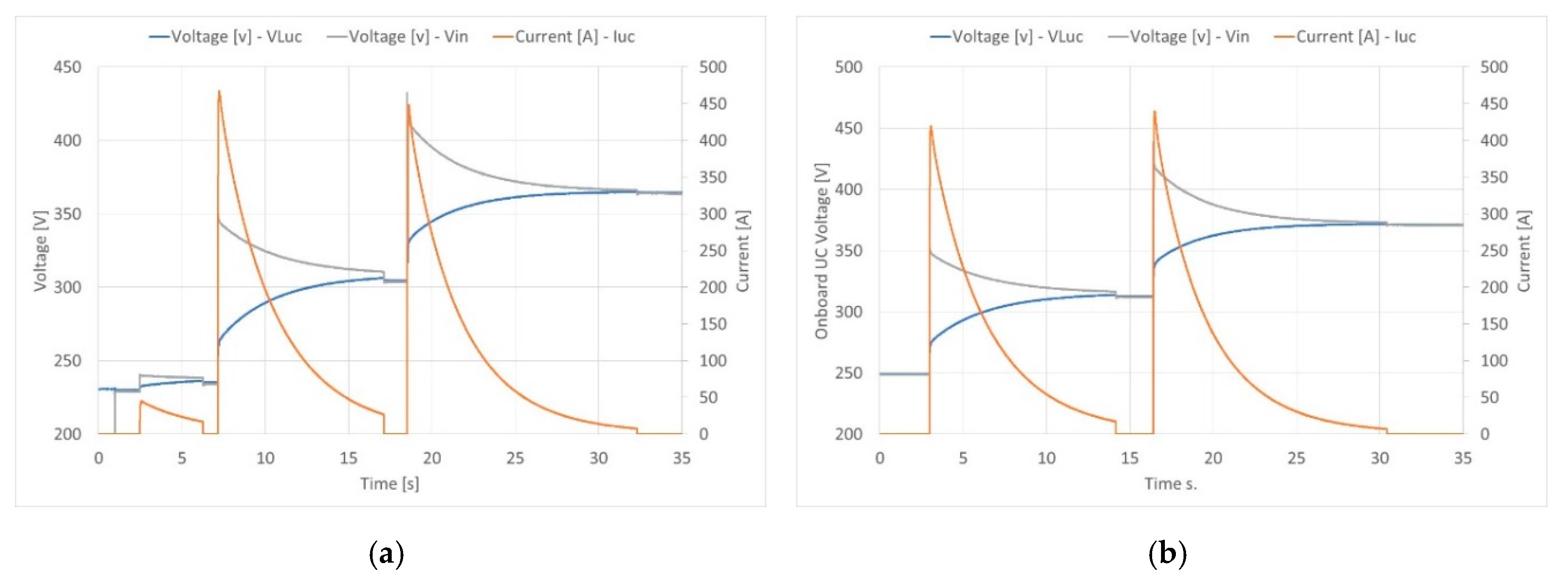
  • Verifying that the charging process is completed within a prefixed time: At this stage the charging process is non-automatized, so from one step to the following one there could be a delay that could be easily removed in the future. The end of each step and the start of the following one is set to when the current falls below a threshold value of 20 A.
  • Verifying that the ground supercapacitors are fully recharged in a fixed period of time in order to be ready to charge the next bus.
  • Verifying that the maximum current and voltage do not exceed the nominal ones: every supercapacitor module has a nominal voltage of 125 V, but only half of this value is used. Hence, the maximum charge voltage is 375 V, while the minimum voltage is 187.5 V
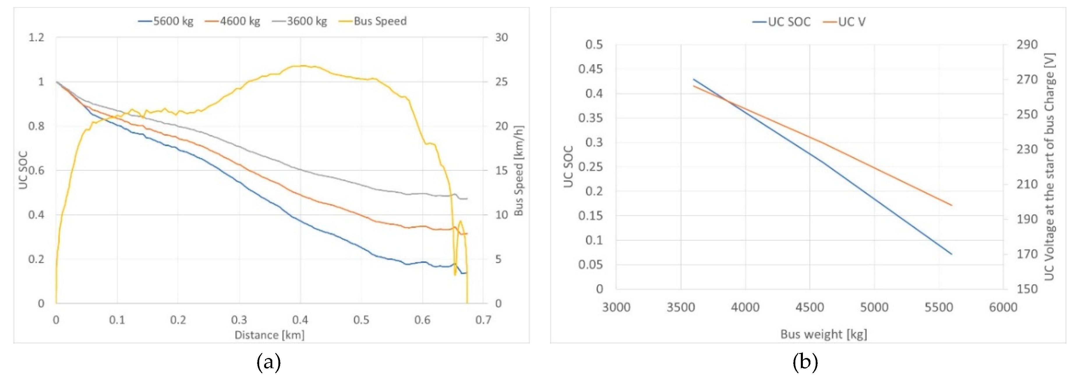
  • Verifying that the charging station is able to charge the bus even if the bus storage has a supercapacitor voltage different from the minimum allowed. The bus energy consumption is not constant during the route, depending on traffic, path, and pay-load. Accordingly, the charging station must be able to charge the onboard energy storage even if it is not completely discharged.
The simulation results performed in one step (1-step) and three steps (3-step) recharge processes for the proposed system are shown in Figure 4 and Figure 5. The 1-step charging is faster, but the 3-step charging is more efficient and the correspondent current is lower. Table 3 shows the comparison between the two charging methods.
It has been found that the test results depend on the initial voltage of the supercapacitors. In Table 2 the extreme conditions of recharge are considered. The voltage and current profile during a charging are shown in Figure 5. The six modules connected as in Figure 2 present different voltage values during the charge. It can be seen from Figure 5 that the three steps can be easily identified, observing three different peak current and the three different voltages (supercapacitor voltages on board the vehicle and the voltage on the ground station).
The maximum peak current, more than 400 A, was obtained during the second step and the supercapacitor module connected in the second step reached the lowest value of voltage at the end of the charge process. The charging time, without the delay times due to the manual drive of the charging steps, was within the 30 s. The charging time of the ground supercapacitors was about 2.5 min.
The charging process when the initial voltage of the onboard supercapacitors was changed from 190 V to 250 V is depicted in Figure 6 and Figure 7. With reference to different onboard voltages, the transfer energy was reduced during the first step due to the different voltage between ground and onboard storage. The current changed from 300 A (for voltage = 190 V) to 220 A (voltage = 230 V). Additionally, the first current step is missing when the onboard voltage is 250 V (Figure 7b).
Thanks to the lighter storage system compared to the original version (powered with 43 kWh lead acid batteries) the unladen weight passed from 4300 kg to about 3500 kg and the gross laden weight from 6300 to 5600 kg. Consequently, the range on a reference circuit, internal to the Enea Casaccia Research Center of about 0.7 km, may range from 320 Wh/km up to 450 Wh/km, depending on the number of passengers transported.
The bus route was performed in different conditions: a full and empty bus. Moreover, the state of charge (SOC) of the supercapacitors was changed from 200 V to 275 V. Figure 8 shows the reference speed profile and the SOC for different bus conditions and different voltages of the supercapacitor tank. As can be seen from Figure 8, the charging station is able to charge the onboard supercapacitors independently of their initial voltage.
Figure 9 shows the final voltage at the end of the charge process as a function of the initial voltage of the supercapacitors. When the onboard SOC is close to zero, the final voltage is about 360 V, and it increases with an increase in the initial voltage. When the initial voltage reaches the maximum value (250 V), the charging station uses the two charge steps to bring the final voltage at 375 V. This is the rated voltage for the supercapacitors; it is not possible to charge the energy storage system of the bus if the initial voltage has higher values. However, the bus has a hybrid storage system composed by batteries and supercapacitors. Some of the energy from the supercapacitors is transferred to the batteries in order to decrease the supercapacitor voltage. Thus, the battery storage on board the bus can be used to discharge the supercapacitors when their voltage is too high. Furthermore, battery storage is used as a backup system when the supercapacitors are totally discharged during the route.

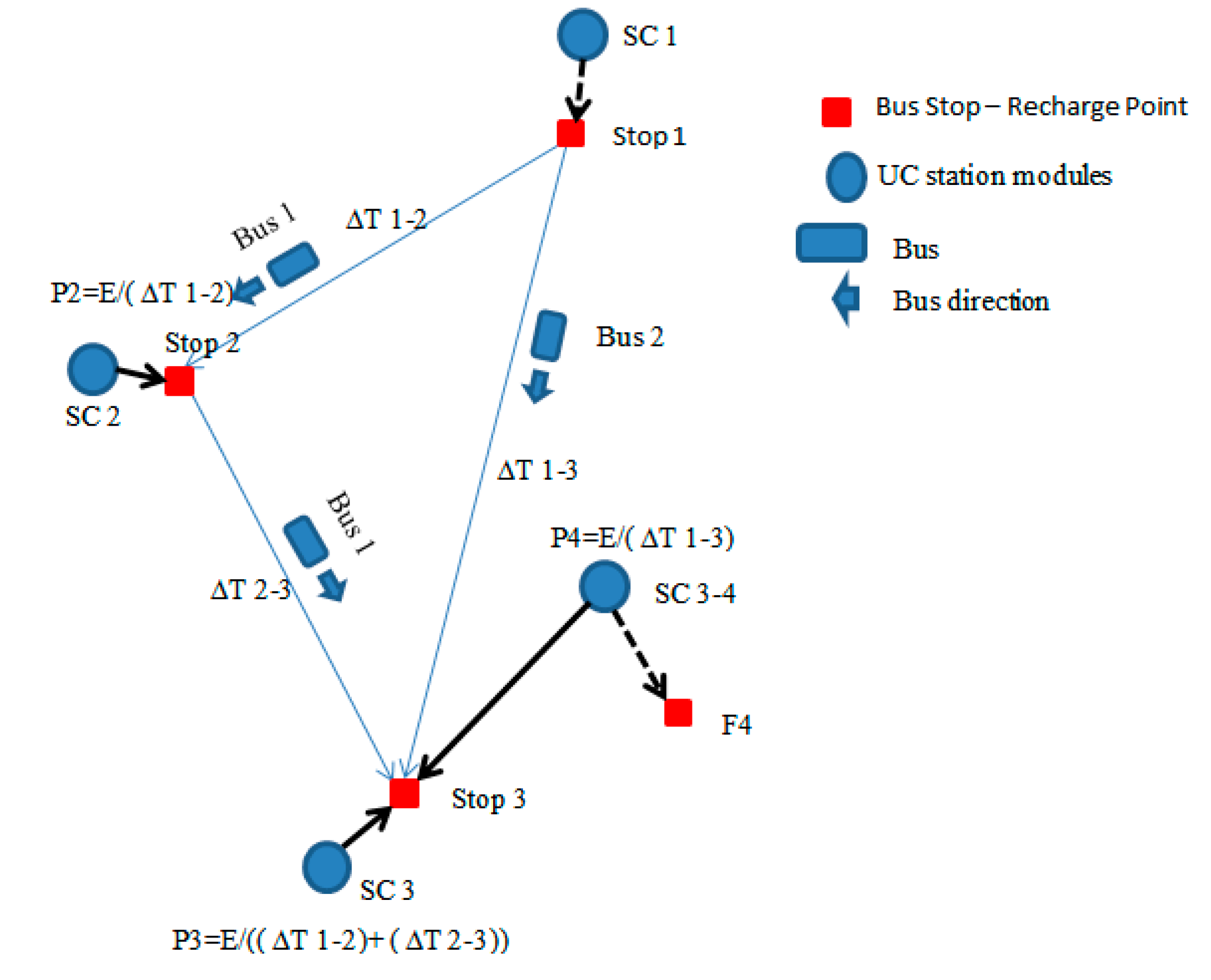
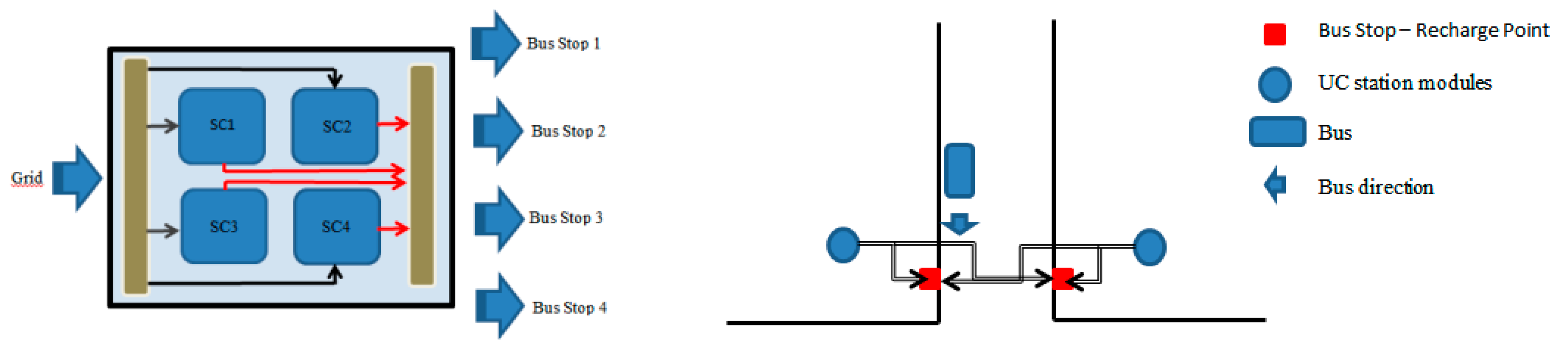
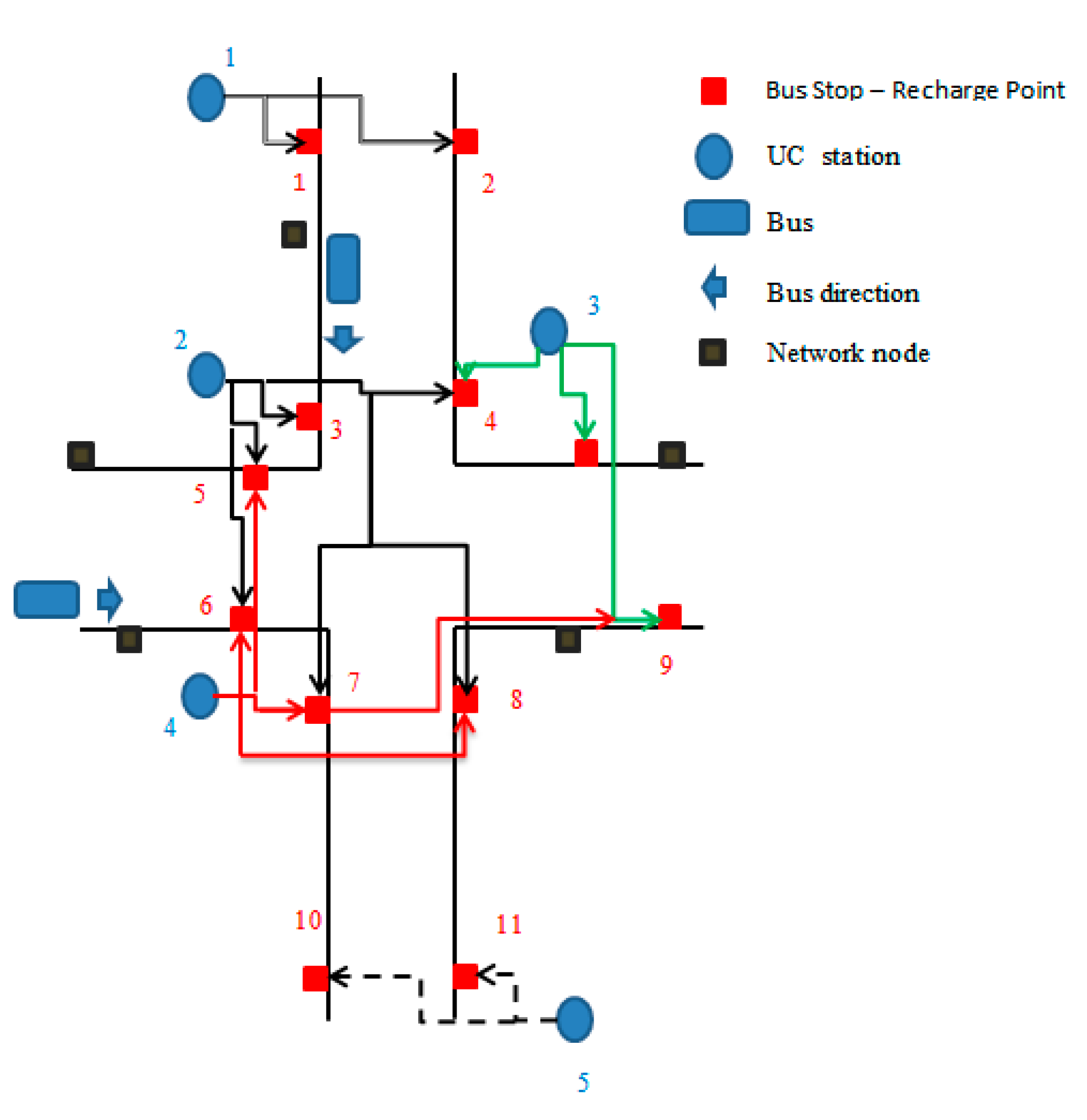
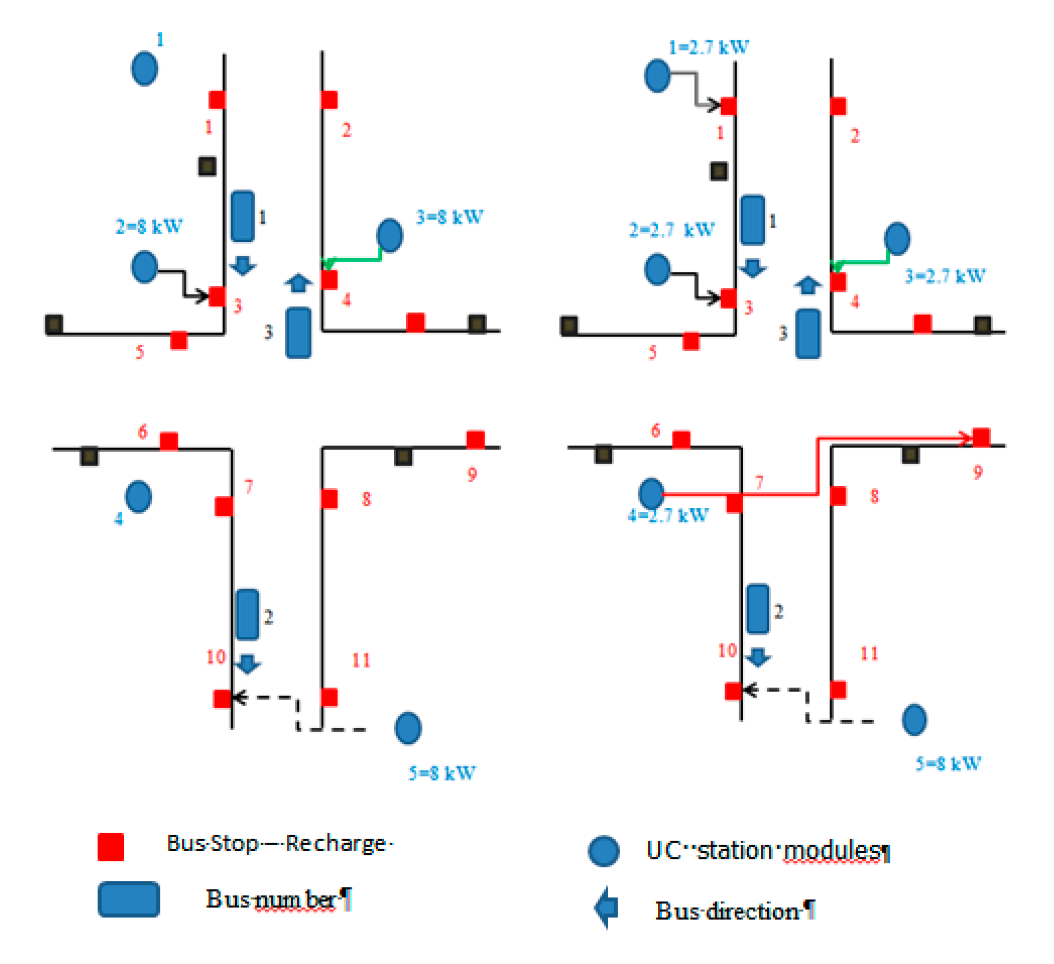
5. Structure of a Charging Network and its Management

In this paper, the structure of a flash charging station in the bus route was considered. Once the feasibility of the idea is verified, it is necessary to consider the charging network building for a complex transport system.
Figure 10 shows how it is possible to connect a supercapacitor bank to different bus stops, and it is also possible to connect a bus stop to different supercapacitor banks.
In this way, it is possible to create a structured flash recharging network.
To build the network the following must be considered:
  • the distance between the different bus stops;
  • the frequency of passing buses;
  • the presence of transformation stations near the stops.
For example, if two stops are very close, and a large interval of time is expected for the passage of the buses, only one bank of capacitors can be used; if instead there are many stops nearby with a high frequency of passing buses it is necessary to provide more banks of capacitors, greater than the number of stops if needed.
A rule that has been established is that if two stops are more than a hundred meters apart then they are not connected.
To manage the network, it is necessary to establish the value of the supercapacitors’ charge power, Figure 11 shows a possible technique for managing the charging power.
From the knowledge of waiting times at the bus stop, a solution for choosing the capacitor recharge power is shown in Figure 11.
The subject of study has been introduced for completeness; it will be explained in more detail in other papers, but to give an example, consider a simplified case.
Consider the following charging network (Figure 12), which can be seen as a system where the status is given by the position of the buses and the SOC of the capacitors on the ground. The input is the direction and speed of the buses, or equivalent, the waiting times at the stops and the output are the SuperCapacitorsconnections with the bus stops and their recharging powers.
In a first example, the waiting time at the stops is considered a multiple of 3 min, the supercapacitors’ recharge power is a constant and equal to 8 kW. In another case, it is possible to choose between three thresholds—8, 4, and 2.7 kW.
The following Table 4 shows the transition times at the stops for four buses.
Table 5 indicates a possible management of the capacitors by adopting a single recharge threshold; the term Cif indicates that the capacitor is connected to the station f.
Table 6 indicates a possible solution with three recharge thresholds.
Figure 13 allows the results to be compared for the same time interval.
The subject of study was introduced for completeness; it will be explained in more detail in the other papers.

6. Conclusions

The preliminary results of a flash charge system for a public transport vehicle characterized by supercapacitors and batteries storage system onboard the vehicle were presented. The charging process was divided into three steps in order to limit the maximum currents.
It can be noticed that such a charging system could be effective from both a technical and economical point of view when used for reduced distance between two adjacent stops. The necessary grid average power can be definitely fulfilled by a common urban light system due to the quite low average value. In fact, the charging process of the ground station is accomplished with a longer time between two different vehicles. The results have confirmed the theoretical, modeling, and experimental study served for sizing and implementing of the 1:1 scale system.
In the final part of the paper, suggestions have been proposed for future improvements of the charging system and for alternative structures of the flash charging stations.

Author Contributions

Funding acquisition, P.P.P.; project administration, F.O.; software, A.L., M.D.B.; writing—original draft preparation, M.P.; writing—review and editing, F.O., M.P and A.L.

Funding

This research was funded by Ministero dello Sviluppo Economico, Project C.5, Energy Storage systems for the electric system, PAR 2017.

Conflicts of Interest

The authors declare no conflict of interest.

References

  1. Su, C.; Yu, J.; Chin, H.; Kuo, C. Evaluation of power-quality field measurements of an electric bus charging station using remote monitoring systems. In Proceedings of the 2016 10th International Conference on Compatibility, Power Electronics and Power Engineering (CPE-POWERENG), Bydgoszcz, Poland, 29 June–1 July 2016; pp. 58–63. [Google Scholar]
  2. Varghese, A.S.; Thomas, P.; Varghese, S. An efficient voltage control strategy for fast charging of plug-in electric vehicle. In Proceedings of the 2017 Innovations in Power and Advanced Computing Technologies (i-PACT), Vellore, India, 21–22 April 2017; pp. 1–4. [Google Scholar]
  3. Yu, H.; Cheli, F.; Castelli-Dezza, F. Optimal Design and Control of 4-IWD Electric Vehicles Based on a 14-DOF Vehicle Model. IEEE Trans. Veh. Technol. 2018, 67, 10457–10469. [Google Scholar] [CrossRef] [Green Version]
  4. You, P.; Yang, Z.; Zhang, Y.; Low, S.H.; Sun, Y. Optimal Charging Schedule for a Battery Switching Station Serving Electric Buses. IEEE Trans. Power Syst. 2016, 31, 3473–3483. [Google Scholar] [CrossRef]
  5. Nademi, H.; Zadeh, M.; Undeland, T. Interfacing an Electric Vehicle to the Grid with Modular Conversion Unit: A Case Study of a Charging Station and its Control Framework. In Proceedings of the IECON 2018—44th Annual Conference of the IEEE Industrial Electronics Society, Washington, DC, USA, 21–23 October 2018; pp. 5171–5176. [Google Scholar]
  6. Ríos, M.A.; Muñoz, L.E.; Zambrano, S.; Albarracín, A. Load profile for a bus rapid transit flash station of full-electric buses. In Proceedings of the IEEE PES Innovative Smart Grid Technologies, Europe, Istanbul, Turkey, 12–15 October 2014; pp. 1–6. [Google Scholar]
  7. Vepsäläinen, J.; Baldi, F.; Lajunen, A.; Kivekäs, K.; Tammi, K. Cost-Benefit Analysis of Electric Bus Fleet with Various Operation Intervals. In Proceedings of the 2018 21st International Conference on Intelligent Transportation Systems (ITSC), Maui, HI, USA, 4–7 November 2018; pp. 1522–1527. [Google Scholar]
  8. Rahbari-Asr, N.; Chow, M. Cooperative Distributed Demand Management for Community Charging of PHEV/PEVs Based on KKT Conditions and Consensus Networks. IEEE Trans. Ind. Inform. 2014, 10, 1907–1916. [Google Scholar] [CrossRef]
  9. Zhai, N.S.; Yao, Y.Y.; Zhang, D.I.; Xu, D.G. Design and Optimization for a Supercapacitor Application System. In Proceedings of the 2006 International Conference on Power System Technology, Chongqing, China, 22–26 October 2006; pp. 1–4. [Google Scholar]
  10. Conti, V.; Orchi, S.; Valentini, M.P. Upgrading del sistema di supporto alle decisioni relativo all’elettrificazione di singole linee di trasporto pubblico locale. Rome, Italy, RdS/PAR2016/226. Available online: http://www.enea.it/it/Ricerca_sviluppo/documenti/ricerca-di-sistema-elettrico/adp-mise-enea-2015-2017/accumulo-di-energia/rds_par2015-193.pdf (accessed on 20 May 2019).
  11. Rossi, E.; Villante, C. A hybrid city car. IEEE Veh. Technol. Mag. 2011, 6, 24–37. [Google Scholar] [CrossRef]
  12. Conte, M.; Genovese, A.; Ortenzi, F.; Vellucci, F. Hybrid battery-supercapacitor storage for an electric forklift: A life-cycle cost assessment. J. Appl. Electrochem. 2014, 44, 523–532. [Google Scholar] [CrossRef]
  13. Ortenzi, F.; Pede, G.; Rossi, E. Lithium-Ion/Supercapacitors Storage System Powered Microcar: Development and Testing. Energy Procedia 2015, 81, 422–429. [Google Scholar] [CrossRef] [Green Version]
  14. Ortenzi, F.; Orchi, S.; Pede, G. Technical and economical evaluation of hybrid flash-charging stations for electric public transport. In Proceedings of the 2017 IEEE International Conference on Industrial Technology (ICIT), Toronto, ON, Canada, 22–25 March 2017; pp. 549–554. [Google Scholar]
  15. Ortenzi, F.; Orchi, S.; Pede, G. Technical and Economical Evaluation of Hybrid Fast-Charging Stations for Electric Public Transport. In Proceedings of the Evs30—Electric Vehicle Symposium & Exhibition, Stuttgart, Germany, 9–11 October 2017. [Google Scholar]
  16. Ortenzi, F.; Pede, M.P.G.; Lidozzi, A.; di Benedetto, M. Ultra-fast charging infrastructure for vehicle on-board ultracapacitors in urban public transportation applications. In Proceedings of the EVS31—The 31st International Electric Vehicles Symposium & Exhibition & International Electric Vehicle Technology Conference 2018, Kobe, Japan, 30 September–3 October 2018. [Google Scholar]
  17. di Rienzo, R.; Baronti, F.; Vellucci, F.; Cignini, F.; Ortenzi, F.; Pede, G.; Roncella, R.; Saletti, R. Experimental Analysis of an Electric Minibus with Small Battery and Fast Charge Policy. In Proceedings of the ESARS-ITEC 2016, Toulouse, France, 2–4 November 2016. [Google Scholar]
  18. Alessandrini, A.; Cignini, F.; Ortenzi, F.; Pede, G.; Stam, D. Advantages of retrofitting old electric buses and minibuses. Energy Procedia 2017, 126, 995–1002. [Google Scholar] [CrossRef]
  19. Alessandrini, A.; Barbieri, R.; Berzi, L.; Cignini, F.; Genovese, A.; Locorotondo, E.; Ortenzi, F.; Pierini, M.; Pugi, L. Design of a Hybrid Storage for Road Public Transportation Systems. In Advances in Italian Mechanism Science. IFToMM ITALY 2018; Mechanisms and Machine Science; Carbone, G., Gasparetto, A., Eds.; Springer: Cham, Switzerland, 2019; Volume 68. [Google Scholar]
Figure 1. (a) Hybrid Storage system on board the bus; (b) and the pantograph for ultrafast charge.
Energies 12 02348 g001
Figure 2. Block scheme of the charging station.
Energies 12 02348 g002
Figure 3. Inductor used in the charging station.
Energies 12 02348 g003
Figure 4. Comparison of 1-step and 3-step charge. (a) Charging current as a function of time, (b) bus supercapacitors voltage.
Energies 12 02348 g004
Figure 5. Voltages and currents as a function of time: (a) station side, (b) onboard side.
Energies 12 02348 g005
Figure 6. Charging process with on board initial voltage of: (a) 190 V, (b) 210V.
Energies 12 02348 g006
Figure 7. Charge process with onboard initial voltage of: (a) 230 V, (b) 250V.
Energies 12 02348 g007
Figure 8. (a) Vehicle speed profile and state of charge (SOC) for different bus weights, (b) voltage of the supercapacitor tank and related SOC.
Energies 12 02348 g008
Figure 9. Final onboard supercapacitor voltage as a function of the initial voltage (as recorded before the charging process).
Energies 12 02348 g009
Figure 10. Proposed structure for the flash charging network.
Energies 12 02348 g010
Figure 11. Proposed criteria for network management.
Energies 12 02348 g011
Figure 12. Example of flash charge network.
Energies 12 02348 g012
Figure 13. Bus position and configuration of the charging network for 6’ < T < 9′ in the two solutions.
Energies 12 02348 g013
Table 1. Tecnobus Gulliver U500 Specification.
ParameterStock VersionFlash Charge Version
Length5.3 m
Passengers28
Max Speed33 km/h
Electric Motor235 Nm@950 Rpm
24.8 kW@1035 Rpm
Auxiliaries consumption~0.9 kW
Weight (kg)4285 (Tare)–6045 (Gross)3500 (Tare)–6045 (Gross)
StorageLead Acid 72V/585 Ah (42.1 kWh)Lead Acid: 72V/120 Ah (8.6 kWh)
Supercapacitors: 375V 63F (410 Wh)
Table 2. Inductor and resistor parameters.
L = 5.4 mH
Resistance = 0.155 Ω
Maximum Current = 500 A
Ku = 0.5
IRMS = 187 A
Table 3. Comparison of 1 and 3 step recharge.
Number StepRecharge Time
[s]
Max Current
[A]
Vcbus Final
[V]
ΔEuc Bus
[kWh]
1241152343.743.58
340513370.753.69
Table 4. Bus travel times and relative stops.
Time (min)03691215
Bus 1N1N3N9
Bus 2N6710NN
Bus 3N11N42N
Bus 4NN11NN9
N = No stop.
Table 5. Management for a single recharge threshold, Power = 8 KW.
Time
(min)
C1
(kW)
C1FC2
(kW)
C2FC3
(kW)
C3FC4
(kW)
C4FC5
(kW)
C5F
081860000811
300000087811
600838400810
98200000000
120000898900
150000000000
Table 6. Management with three recharge thresholds, P = 2.7,4, and 8 KW.
Time
(min)
C1
(kW)
C1FC2
(kW)
C2FC3
(kW)
C3FC4
(kW)
C4FC5
(kW)
C5F
0812.732.7486811
32.722.732.7487811
62.722.732.742.79810
92.7200492.7900
120000492.7900
150000000000

