Experimental Investigation on Performance Comparison of Solar Water Heating-Phase Change Material System and Solar Water Heating System


School of Mechanical Engineering, Southwest Jiaotong University, Chengdu 610031, China
*
Author to whom correspondence should be addressed.
Energies 2019, 12(12), 2347; https://doi.org/10.3390/en12122347
Submission received: 7 May 2019
/
Revised: 6 June 2019
/
Accepted: 11 June 2019
/
Published: 19 June 2019
(This article belongs to the Special Issue Building Renewable Energy and Thermal Energy Storage System 2019)
Abstract
:Phase change material can be used as heat transfer fluid in the solar water heating system, which is the latest way to improve thermal efficiency. In this paper, graphene composite paraffin emulsion is used as heat transfer fluid in a solar water heating-phase change material (SWH-PCM) system. By comparing with the traditional solar water heating (SWH) system, the thermal performance characteristics of SWH-PCM system have been investigated experimentally. The SWH-PCM system has higher heat storage than the SWH system. The heat storage of SWH-PCM system and SWH system all increase with the increase of solar irradiance, while the thermal efficiency has the opposite trend. The flow rate has a greater influence on the thermal efficiency of SWH-PCM system than that of the SWH system. With the flow rate of 200 L/h, the thermal efficiency of SWH-PCM system is 14.21% higher than that of the SWH system. In summary, the SWH-PCM system is a promising solar water heating system with high heat storage and thermal efficiency.
1. Introduction
Energy shortage is one of the most challenging issues around the world. It is urgent and necessary to adjust the energy structure of the world. There are two solutions to energy shortage; one solution is to replace the existing fossil fuels using clean and renewable energy, such as solar energy, wind energy, tidal energy, biomass, etc. The other solution is to enhance the energy utilization efficiency. Solar energy, as a clean, renewable and abundant energy source, has become an effective alternative to fossil fuels. The solar energy application range is very wide and divided into two categories from the perspective of its utilization. Photovoltaic power generation is based on the theory of photovoltaic effect, making solar cells convert solar energy directly into electrical energy. The other one is photothermal utilization, which is to use the solar collector to provide hot water/air for daily life, directly for heating, also can be used in the seawater desalination, solar drying and so on. The solar thermal system is used to collect solar radiation from the solar collector for further utilization, and the solar water heating system accounts for 80% solar thermal utilization in the worldwide [1,2]. For the solar water heating system, the research focus has always been to improve the thermal efficiency of the system and reduce the heat loss of the system.
Phase change materials are a kind of material, which can storage energy by latent heat under approximate constant temperature. The phase change materials have caught the attention of scholars due to their high storage density and ability to transfer energy in time and space [3,4,5]. With the study of phase change materials, there are more and more scholars put forward phase change materials into functional fluids as heat transfer medium. The functional fluids have many advantages, such as: (1) High specific heat during phase transformation; (2) the heat storage medium and the heat transfer medium at the same time; (3) relatively low transfer temperature range; (4) higher heat transfer efficiency during the phase change; (5) lower quality of fluid under the same heat transfer rate [6]. Wang et al. [7] have reviewed the development of the existing PCM-SWH system and put forward the direction of the research. The review divided into two parts, one for the proposed new system, the other for the economic analysis of the original system. Ma et al. [8] investigated the flow and heat transfer characteristics of a nanosized PCME in mini-tubes. The heat transfer performance of the PCME was better than that of water at a similar Reynolds number. The local heat transfer coefficient increased with the increase of the flow rate but decreased with the increase of the heating power.
Most of the studies are straight tube experiments with the purpose of studying the characteristics of the emulsion. Zou et al. [9] compared the pump power consumption between phase change emulsion and water through the experiment. He indicated that the pump power consumption of emulsion was reduced by 73% with a velocity of 0.6 m/s compared with water. The 30% phase change emulsion consumed nearly the same electricity as 20% emulsion. Ni et al. [10] studied the forced convective heat transfer of paraffin in laminar flow by both experiment and numerical simulation. It was found that paraffin had a ratio of 9.8–10.7 times higher than that of water and the value was related to the flow velocity. Sampo et al. [11] analyzed the convective heat transfer characteristics of the emulsion by experimental investigation. When the Reynolds number was between 2300 and 6000, the Nusselt number of the emulsion was similar to that of the basic liquid. But when the flow was close to completely turbulent (Re > 7000), most of the nanofluids presented higher Nusselt number, maximum by 13–15%. While the convective heat transfer coefficient was slightly less than a Nusselt number for ascension, and the thermal conductivity was slightly lower than that of the base fluid. Similarly, Arttu et al. [12] found that the convective heat transfer coefficient of nanofluids was 40% higher than that of the base solution in the turbulent flow. The smaller and more regular shape was better for the heat transfer efficiency of the nanoparticles. At the same time, the thermal transfer efficiency increased with the increase of the concentration of nanoparticles. This phenomenon was also described by Xie et al. [13]. The effects of the wall heat flux, Reynolds number, and mass fraction of PCM on the heat transfer performance of PCMEs were systematically studied by Morimoto and Kumano [14]. The maximum Nusselt number of the PCME was twice as large as that of a single-phase fluid. The heat transfer coefficient increased as the wall heat flux decreased or the PCM mass fraction increased but was essentially unaffected by the Reynolds number.
The improvement of the convective heat transfer coefficient also proves that the phase change emulsion has superiority in improving the thermal efficiency compared to water. Some scholars have further studied the improvement of thermal efficiency of the composite solar system with phase change materials. Wang et al. [15] proposed a new type of heat pipe building integrated electrical/thermal system, and the phase change material is filled into the gap between the heat pipe and the insulation material. The average thermal efficiency, electrical efficiency, and total efficiency of the system were 61.1%, 7.8%, 68.9% respectively. The water tank temperature could be 47.23 °C, under conditions of the radiation intensity of 900 W/m2 and flow rate of 600L/h. Compared with the traditional system, the thermal efficiency increased by 25.5%. Serale et al. [16] compared the 50% phase change emulsion based solar collector and water-based solar collector by numerical simulation. Giving a conclusion that emulsion as a heat transfer fluid could improve the thermal efficiency by 5–10%, while in winter the thermal efficiency was 20–40% higher than that of water-based system. Qiu et al. [17] prepared a new kind of phase change microcapsule suspension as heat transfer medium of PV/T system. The increasing solar radiation had a positive effect on the heat and power output, but also had a negative impact on thermal efficiency. The optimal radiation range for PV/T system was proposed as 500–700 W/m2. Zhao et al. [18] measured the heat transfer performance of 13 wt% and 40 wt% tetradecane/water emulsions of laminar flow in a circular double-tube. It is found that the convective heat transfer performances were greatly enhanced during the phase change process. Mikkola et al. [19] measured the heat transfer performance of 5.0, 7.5, and 10.0 wt% paraffin with an annular-tube heat exchanger. The heat transfer coefficients of all the PCMEs were greater than that of water for both laminar and turbulent flow. Wang et al. [20] proposed 20 wt% PCMEs containing different mass fractions of graphite nanoparticles as HTFs for a direct absorption solar collector. The experimental results indicated that the dispersion of graphite nanoparticles significantly improved the photothermal performance of the PCME.
Most of the existing studies have focused on the flow characteristics and heat transfer properties of the phase change emulsion by experiment or simulation. Just now, there are few articles focusing on performance comparison between the SWH-PCM system and the traditional SWH system through experiment. This paper will set up an experiment rig and investigate the thermal performance of the SWH-PCM system and traditional SWH system. The influence of solar irradiance and flow rate on the heat transfer enhancement, heat storage and thermal efficiency of two systems will be also analyzed experimentally.
2. Experiments
In this paper, the self-made graphene composite paraffin emulsion was used in the experiment. The experiment rig will be set up in an indoor lab, which has a solar simulator. The comparison experiment of the SWH-PCM system and traditional SWH system will be carried out under different solar irradiance and flow rate, which are two main and important influence factors in the heat transfer coefficient, heat storage, and thermal efficiency of two systems.
2.1. Materials
In order to increase the thermal conductivity coefficient and decrease the supercooling of paraffin emulsion, graphene particles were added as the additives. After adding graphene, the thermal conductivity coefficient increased by 20.22% and the supercooling degree dropped from 14.23 °C to 2.13 °C [21].
Related characteristics of the graphene composite paraffin emulsion are listed in Table 1. Each performance parameter is the average value of the measured data of three times.
The specific heat of the emulsion is measured by Differential Scanning Calorimeter (DSC), as shown in Figure 1. The type of DSC used in the measurement is Q20, manufactured by TA instrument corporation. During the measurement, the temperature scanning rate is 5 °C/min and the flow rate of nitrogen is 50 mL/min. The mass of PCE sample is 10 mg. There are two melting processes because paraffin is the mixture of a series of alkane. For the emulsion of 25 kg, the latent temperatures of the two melting processes are 155.75 kJ and 514.50 kJ, respectively. The total latent heat during the whole melting process is 670.25 kJ. The emulsion just starts to melt as temperature rises up to 30 °C and is melted completely when it reaches 65 °C. The specific heat of the emulsion has a large variation rage due to the phase change process. The specific heat of the emulsion used in this experiment is 4.089 kJ·kg−1·K−1, which is the average of 4.0817 kJ·kg−1·K−1 and 4.097kJ·kg−1·K−1, which are specific heat values measured at 30 °C and 65 °C, respectively.
2.2. Experimental Rig
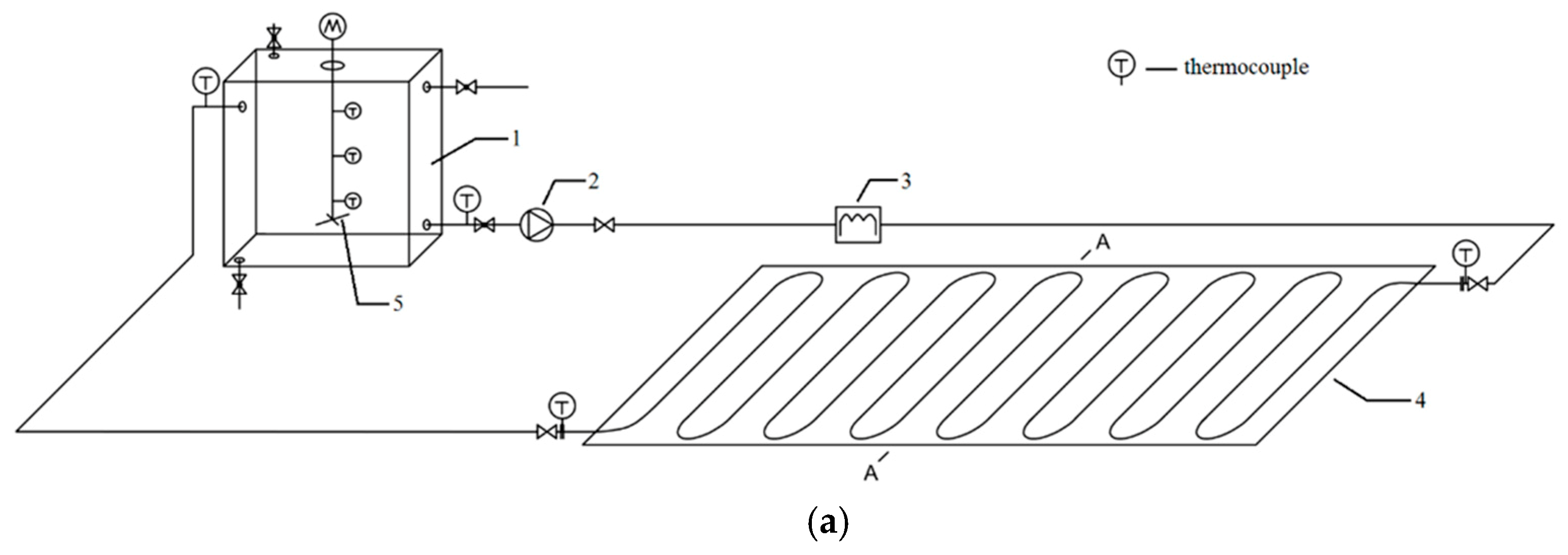
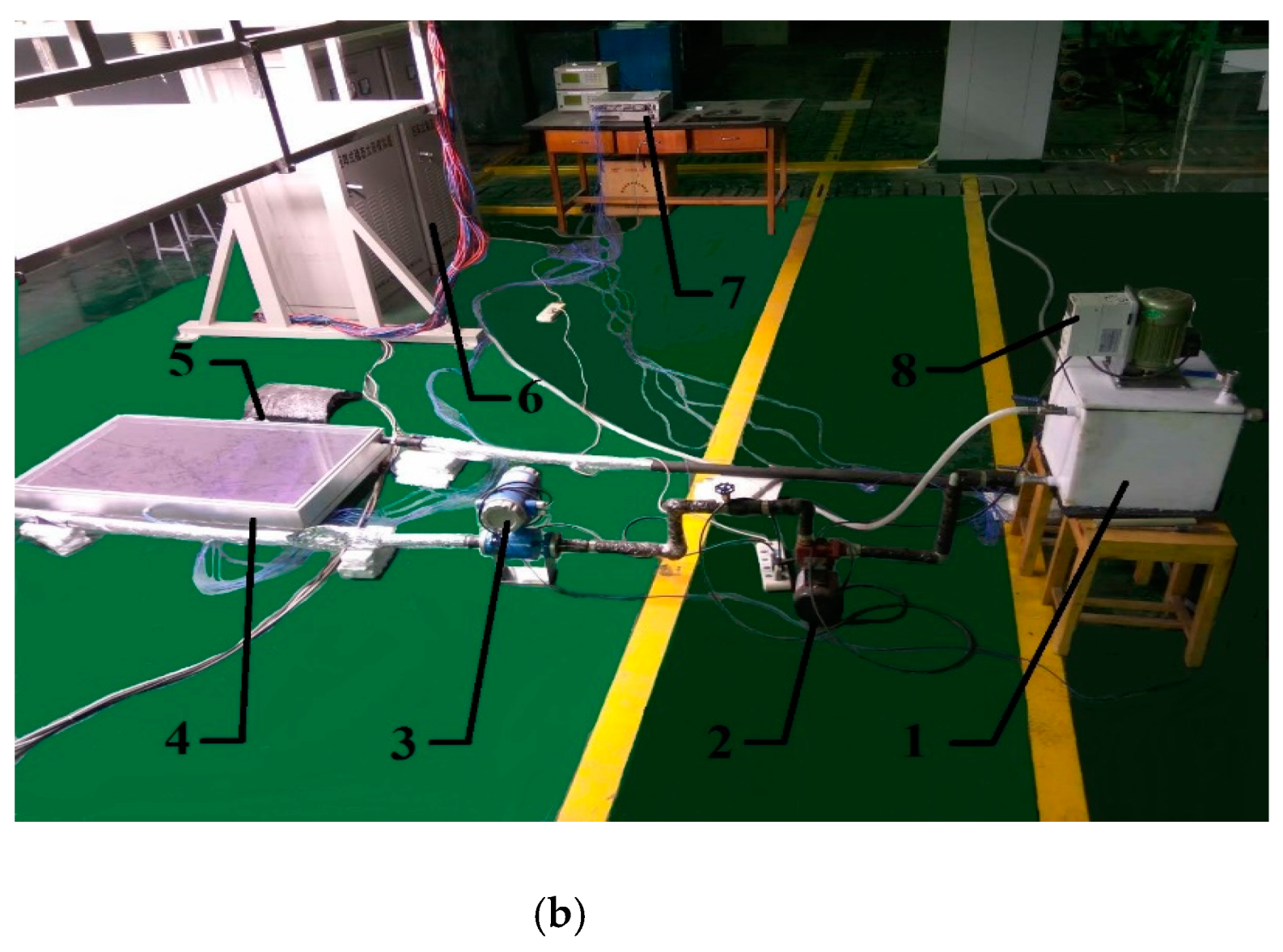
The experimental rig, as indicated in Figure 2, consists of the heat storage tank, centrifugal pump, electromagnetic flowmeter, solar collector, data logger, total radiometer, and solar simulator. Related measuring range and accuracy are listed in Table 2.
As shown in Figure 2, the solar simulator is used to provide radiation as the sun. The solar simulator is made of xenon lamps, with the spectrum of AM 1.5. The provided solar radiation is 0–1200 W/m2. The inhomogeneity and instability of solar radiation are 5%. The solar simulator can cover the area of 2000 mm × 2000 mm. The centrifugal pump installed between the heat storage tank and solar collector is used to provide the impulse for the whole system. The flow rate is adjusting by the opening of the needle valve between the pump and flowmeter. The flow medium is heated while passing through the solar collector, absorbing heat from the absorber plate and then pumped into the heat storage tank. In order to ensure the accuracy of the experiment and reduce the heat loss, the thermal insulation material is covered on the outside surface of the circulating pipe and heat storage tank. In addition, the outside surface of the circulating pipe and heat storage tank are also covered with aluminum foil to prevent the radiant heat gain from the solar simulator.
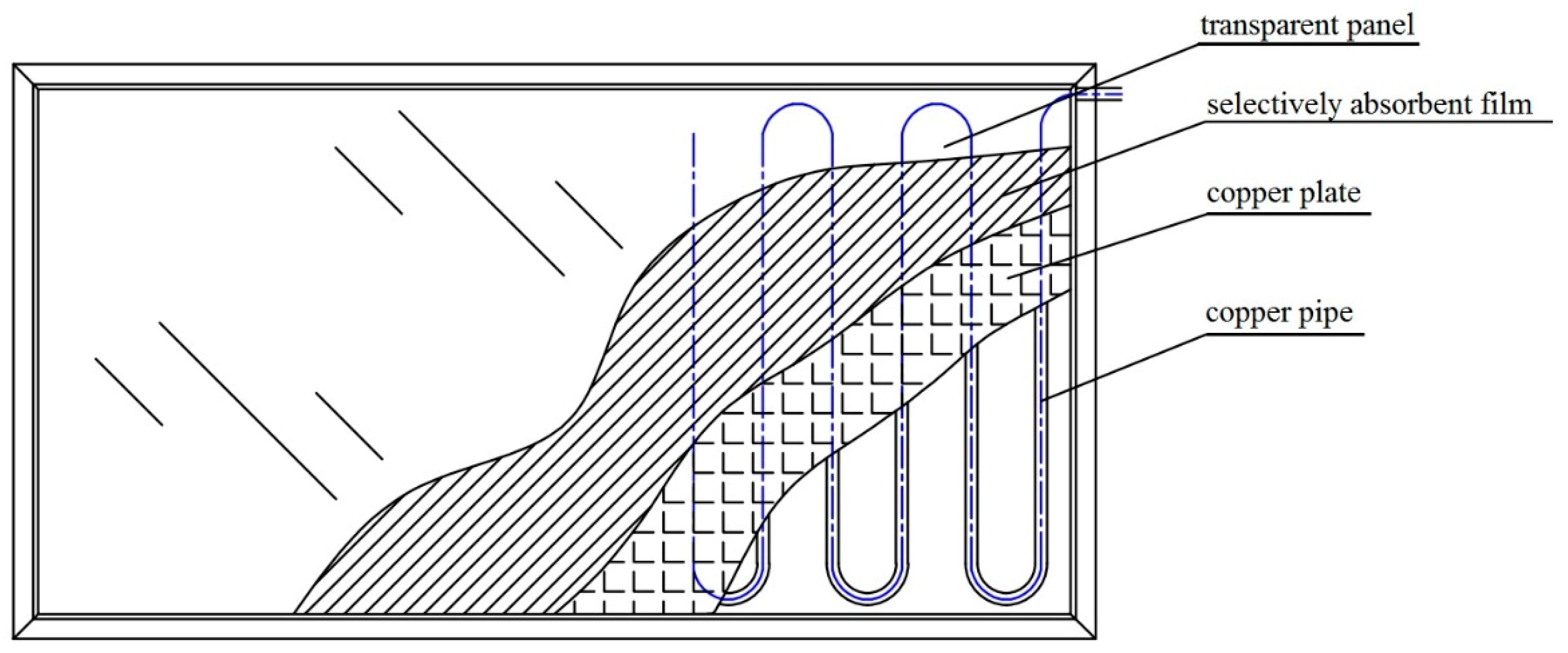
The detailed structural parameters of the solar collector are listed in Table 3, and its schematic diagram is drawn in Figure 3. The technical parameters of PPR pipe used as connecting pipe are as follows: Density of 0.9 g/cm3, modulus of elasticity (20 °C) of 800 MPa, thermal expansion of 1.8 × 10⁻⁴ 1/K, thermal conductivity is 0.2 W/(m·K). The diameter of the circulating pipe is 15 mm, and the diameter of the tube in the solar collector is 12 mm.
The heat storage tank is made of plastic, whose heat conductivity coefficient is much lower than that of metal. The dimension of the heat storage tank is 0.3 m × 0.3 m × 0.3 m. In order to obtain accurate fluid temperature in the heat storage tank, three thermocouples are arranged evenly in the vertical direction. As indicated in Figure 4, the thermal stratification of the thermal storage tank is insignificant for both SWH-PCM system and SWH system. The maximum temperature differences in the thermal storage tank are 0.2 °C. Hence, the fluid temperature in the heat storage tank can adopt the average values of three thermocouples.
2.3. Experimental Conditions
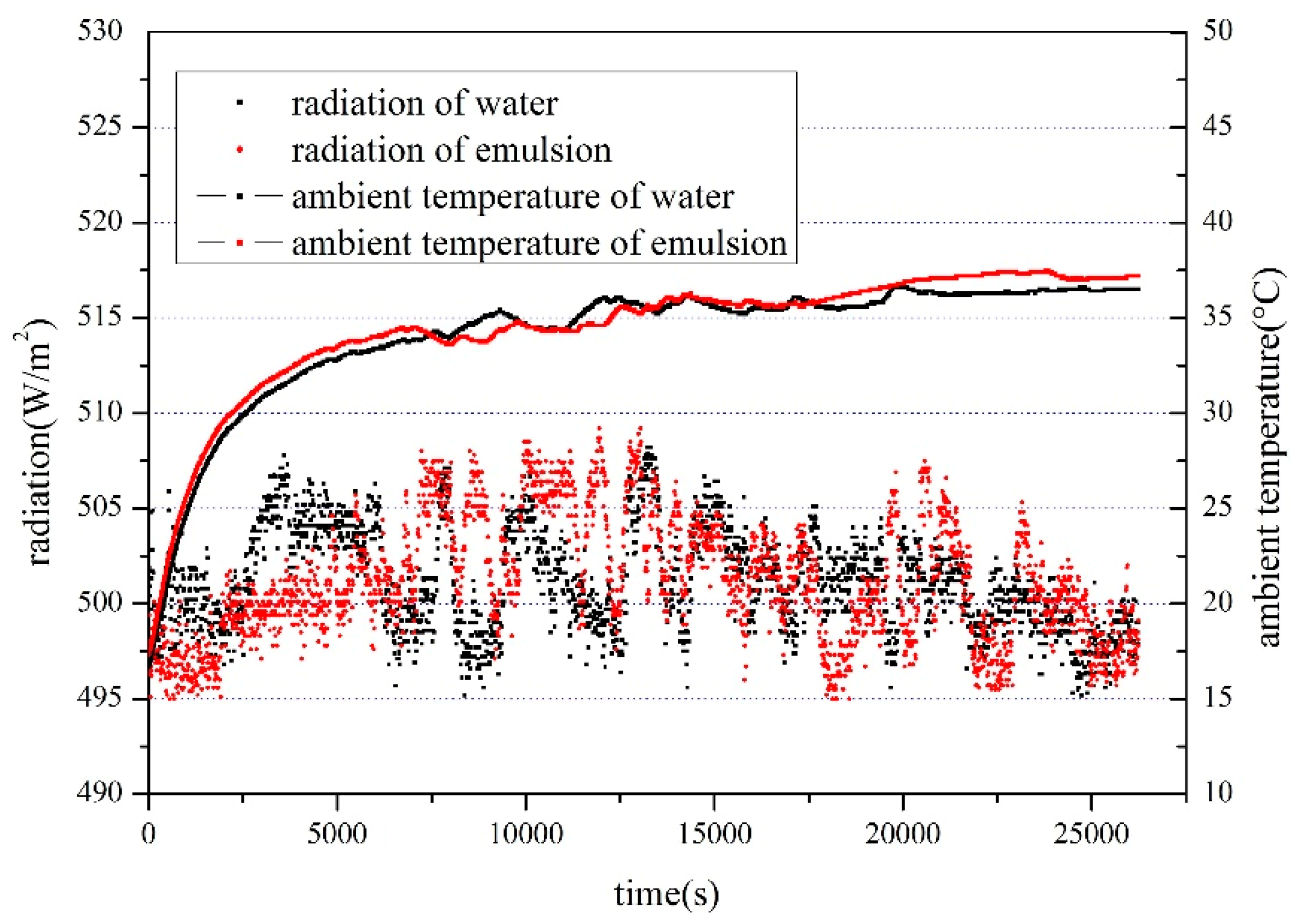
Because of the limited experimental conditions, the comparison experiment of the emulsion and water cannot be carried out simultaneously. It is necessary to analyze differences of solar radiation and ambient temperature under different experimental conditions. Take the solar radiation of 500 W/m2 as an example, as illustrated in Figure 5. The average relative error of the solar radiation is around ±0.6%, and the maximum error is 2.2%. The average relative error of ambient temperature is ±1.8%, and the maximum error is 5.7%. Therefore, the differences of solar radiation and ambient temperature between different experimental conditions can be ignored.
3. Calculation of Heat Storage and Thermal Efficiency
3.1. Heat Storage
Sensible heat can be expressed as:
where Qs—sensible heat, kJ; M—mass of the heat transfer fluid, kg; Cp—specific heat, kJ·kg−1·K−1; Tfinal—the fluid temperature in the heat storage tank at the end of the experiment, °C; Tinitial—the fluid temperature in the heat storage tank at the beginning of the experiment, °C.
Latent heat can be expressed as:
where Qh—latent heat storage, kJ; h—enthalpy of heat transfer fluid, kJ·kg−1.
When the graphene composite paraffin emulsion is used as the heat transfer fluid, the total heat storage is the sum of sensible heat and latent heat, i.e.,:
3.2. Thermal Efficiency
Thermal efficiency can be expressed as:
where I—solar irradiance, J·m−2; AC—effective area of solar collector, m2.
4. Results and Discussion
4.1. Comparison of Heat Storage between Water and Composite Paraffin Emulsion
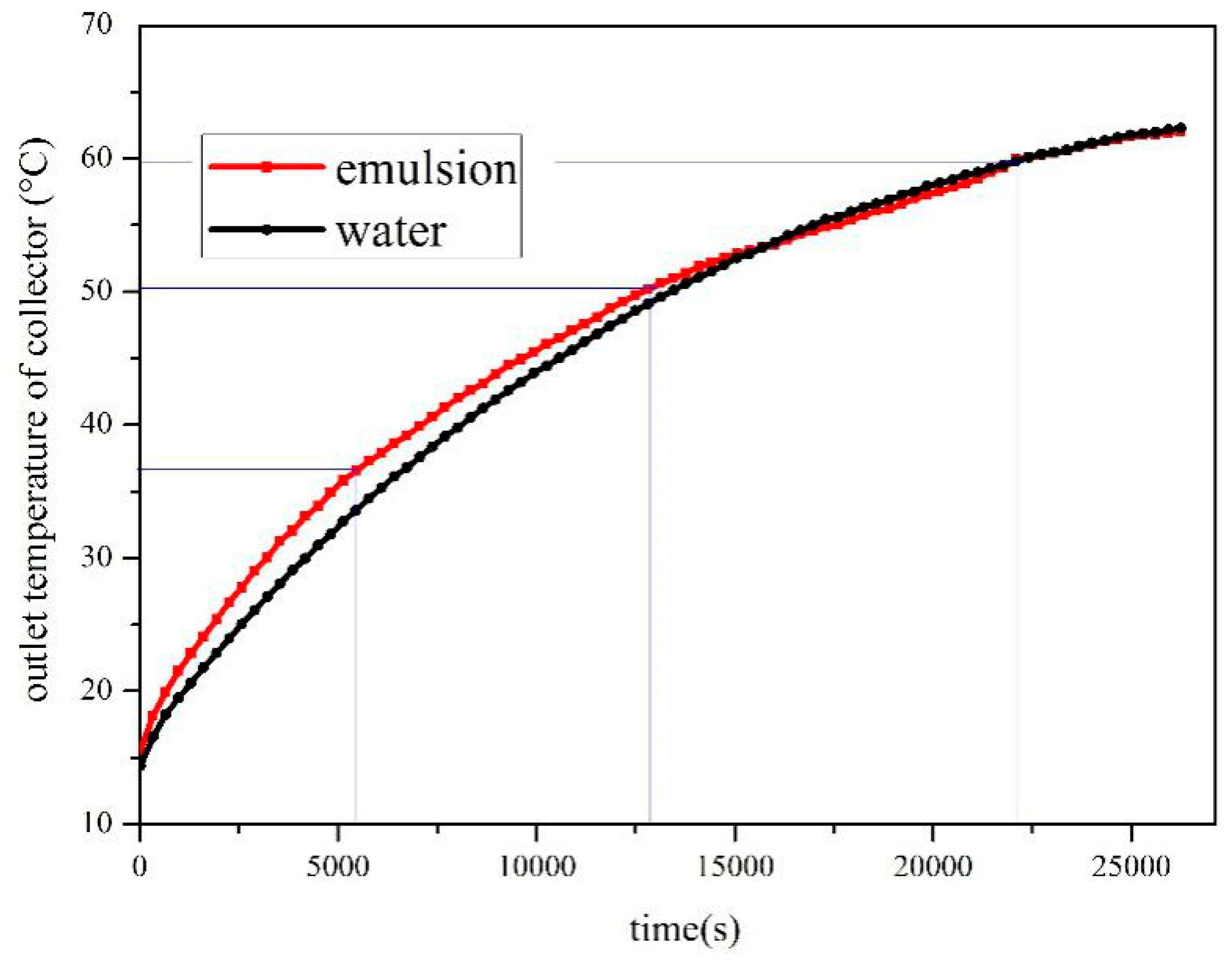
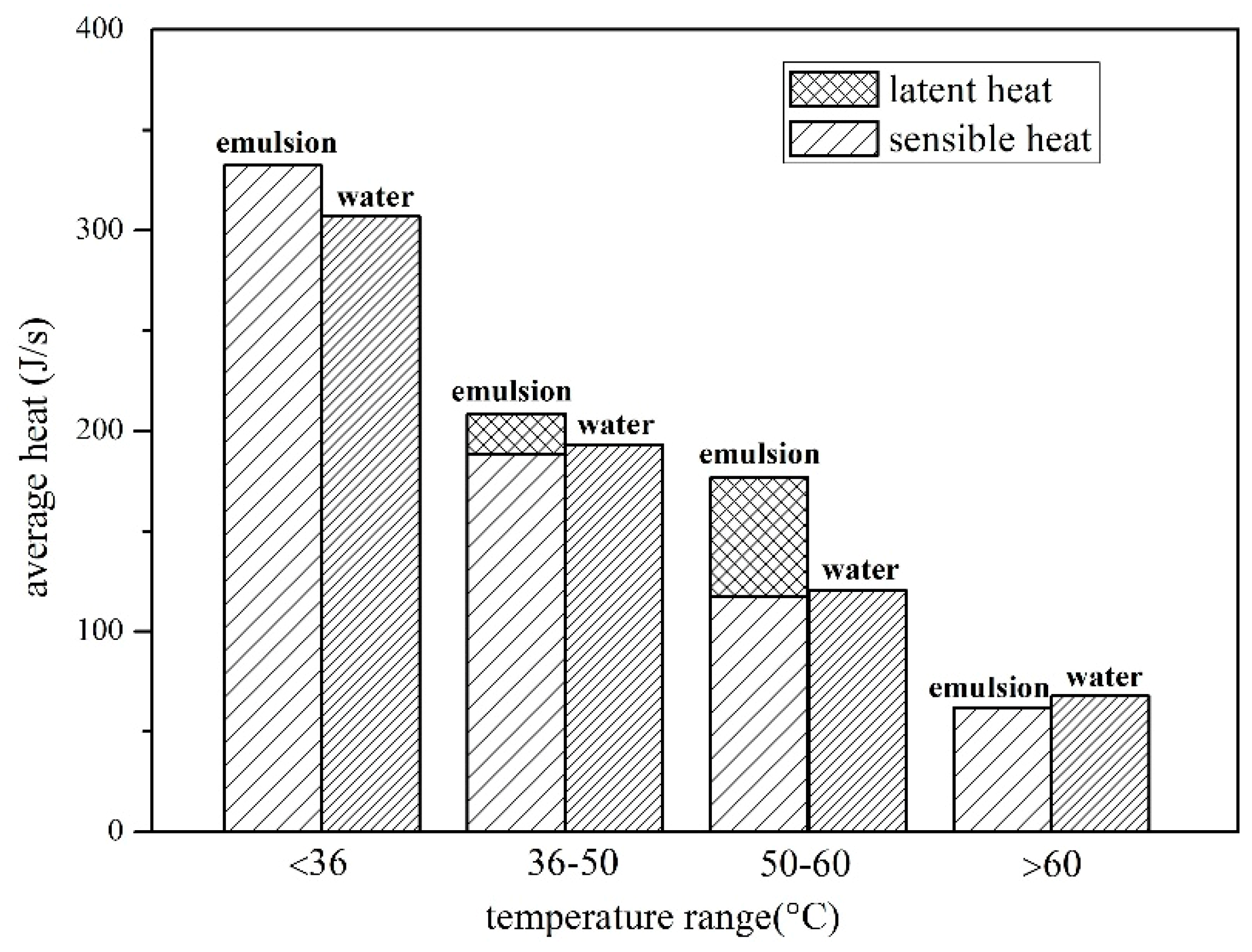
In this part, the heat transfer characteristics of the composite paraffin emulsion and water are compared under the solar irradiance of 500 W/m2 and the flow rate of 550 L/h. The outlet temperature of the solar collector is illustrated in Figure 6. It is found that at the early stage of the heating (0–36 °C), the emulsion has a higher temperature rising rate because the convective heat transfer coefficient of the emulsion is higher than that of water. In this stage, the emulsion is made of water and solid paraffin particles. The reason is that brown diffusion and heat transfer of paraffin particles both lead to enhance the sliding of particles in water, which can increase the convective heat transfer coefficient. The enhancement of heat transfer coefficient by introducing nanoparticles into water has also been founded in other earlier studies [12,13,14,15]. As the temperature increases to 36 °C, the paraffin begins to melt and experience the first melting process. The temperature rising rate of the emulsion has a certain decline since part of heat is stored as latent heat in this process. While the temperature reaches up to 50.4 °C, the phase change material meets the second melting process. In this process, the temperature rising rate of the emulsion continues to slow down and is even slower than that of the water. At the end of the second melting process, the emulsion begins to present the approximate temperature curve with water, since all the solid paraffin particles are melted. At the end of the experiment, the SWH-PCM system has a similar temperature rise with the SWH system. However, due to the lower apparent specific heat, the average sensible heat gain of SWH-PCM system is lower than that of SWH system, as indicated in Figure 7. It can be also founded that the average heat storage of emulsion decreases with the increase of temperature, which has a similar changing trend as its temperature rising rate.
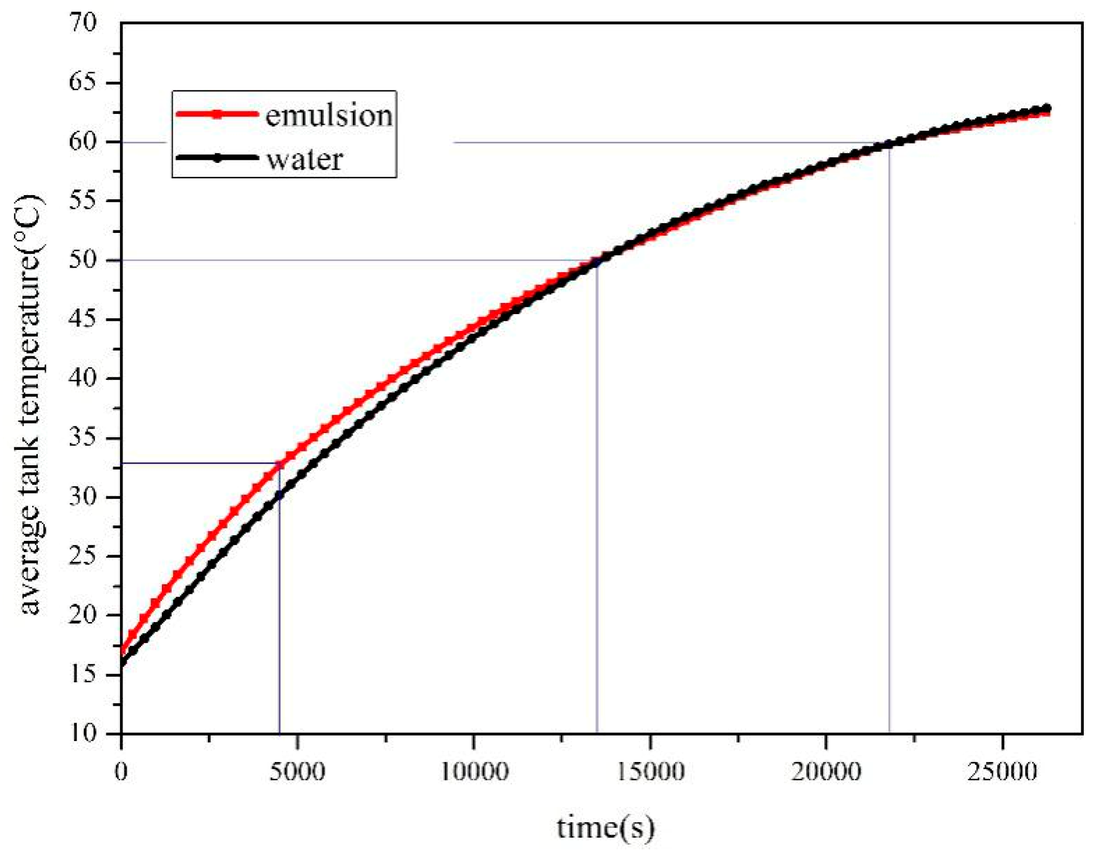
The temperature curve of the heat storage tank is shown in Figure 8. It indicates that the temperature rising rate in the tank is faster than that of water when all the paraffin particles are solid, and the temperature rising rate slows down when the part of paraffin particles begin to melt. The difference between the average tank temperature curve and the collector outlet temperature curve is that the former seems smoother. The reason is that there is a large amount of emulsion in the storage tank.
4.1.1. Effect of Solar Radiation on Heat Storage
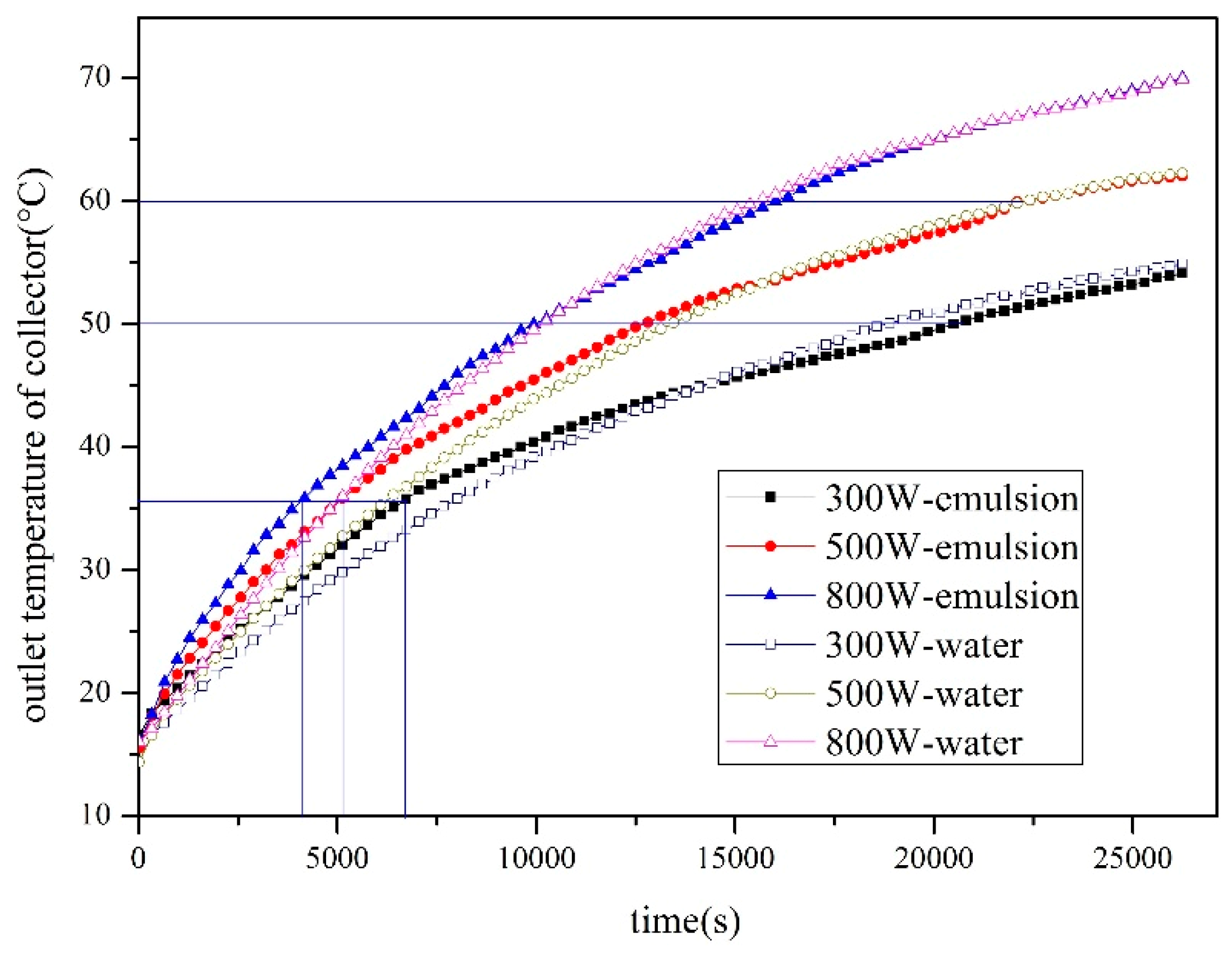
The performance of the two systems has been compared under different solar radiations, including 300 W/m2, 500 W/m2 and 800 W/m2. As the solar radiation increases, the outlet temperature of both systems increases, as shown in Figure 8. The temperature rises of SWH-PCM systems under 300 W/m2, 500 W/m2 and 800 W/m2 are 35.52 °C, 45.57 °C and 52.37 °C, while SWH system temperature is 35.34 °C, 45.62 °C and 52.41 °C. Moreover, due to the lower radiation, the phase change process lasts a longer time than that of higher radiations. Thus, the phase change process under the radiation of 300 W/m2 was uncompleted when the experiment ended. Therefore, at the end of the experiment, the paraffin particles in the emulsion did not melt completely. It also indicates that these temperature curves are similar, although the phase change processes of higher solar irradiances tend to be less and less obvious since their phase change processes are accelerated. The acceleration of phase change can also be observed by comparing the average latent heat of different solar irradiances, as illustrated in Figure 9. When the total latent heat is fixed, the phase change time can be shortened due to the increase of average latent heat. It can be concluded from Figure 10 that the increase of solar irradiances can both increase the average sensible heat and latent heat. In addition, under the solar irradiance of 300 W/m2, the latent heat of emulsion is unable to calculate in the temperature range of 50–60 °C due to the unknown melting fraction.
According to Figure 11, the temperature curves of the storage tank can be obtained. The temperature curves and phase change processes are observed similar to Figure 9. Due to the large amount of emulsion in the tank and the stirring of the agitator, the temperature curves in the tank are smoother and more stable than that of the collector.
4.1.2. Effect of Solar Radiation on Heat Storage
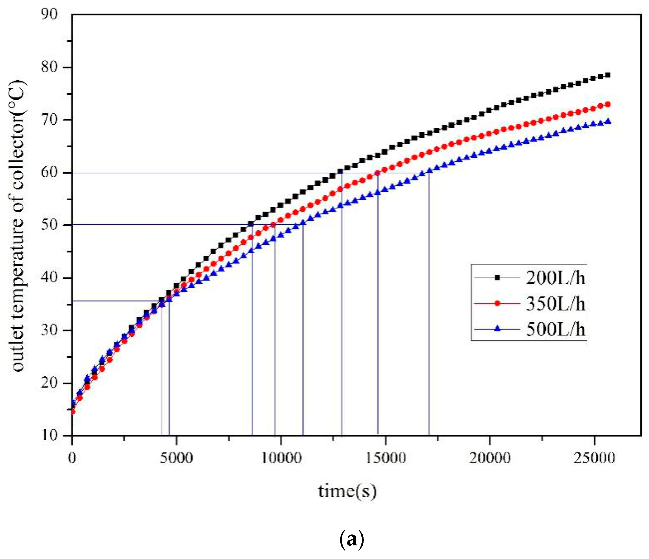
The influence of flow rate on the performance of two systems is studied. The collector outlet temperature curves of the SWH-PCM system and the SWH system with the radiation of 800 W/m2 are illustrated in Figure 12. The impact of the flow rate on thermal performance of the emulsion is much significant than that of water, because the temperature of SWH system almost does not change as flow rate varies. For the same flow rate, the temperature rise of SWH-PCM systems is higher than that of the SWH system. Hence, the heat transfer between the emulsion and the collector is more effective and reasonable under lower flow rates, and the energy consumption of the pump can be reduced. It is obvious that the temperature rise of the emulsion is obviously decreased as increasing flow rates. The reason is while the flow rate increases, the quantity of heat carried is reduced. This will affect both the sensible heat storage and the latent heat storage, as indicated in Figure 13.
4.2. Comparison of Thermal Efficiency between Water and Composite Paraffin Emulsion
4.2.1. Effect of Solar Radiation on Thermal Efficiency
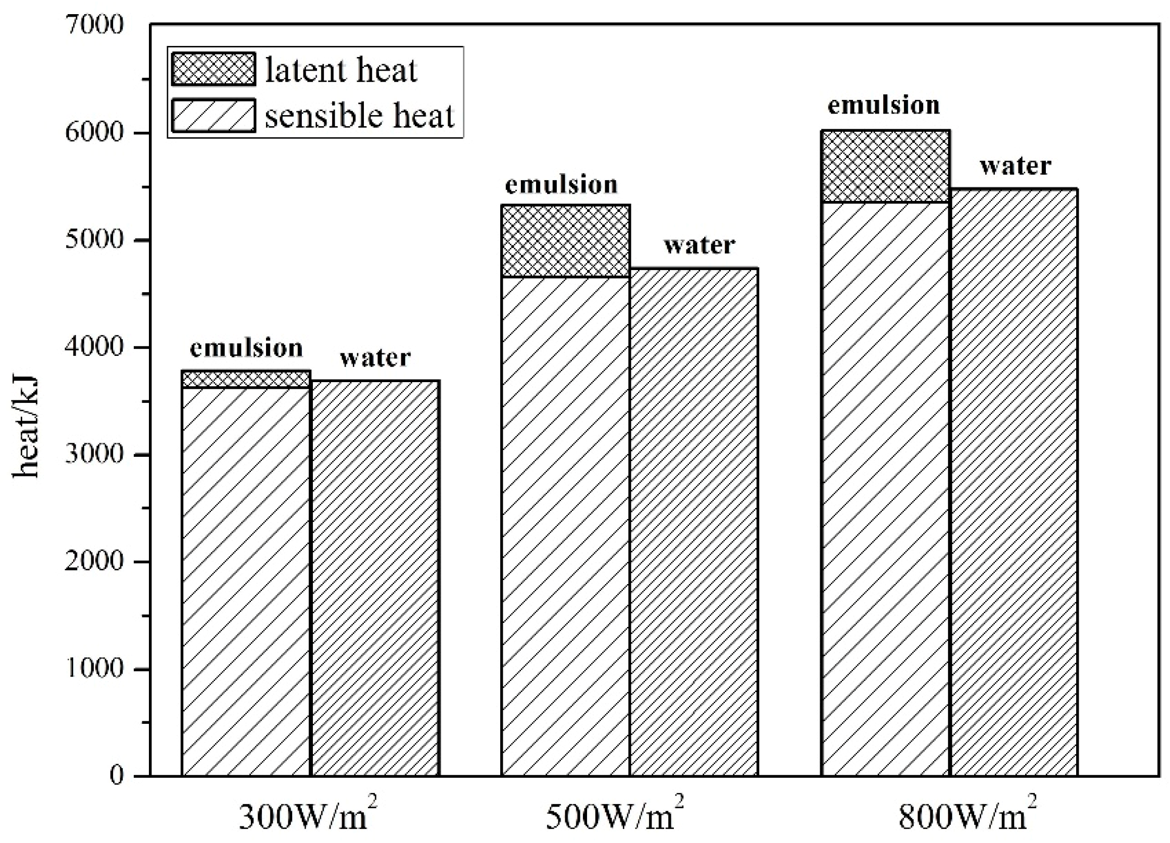
The heat storage of SWH-PCM system and SWH system under different solar radiations are shown in Figure 14. The sensible heat storage of both emulsion and water increases as solar radiations increase. The sensible heat storage of emulsion is less than that of water, due to lower specific heat. As the solar radiation is 300 W/m2, due to the unknown fraction of the melting emulsion, the latent heat of the emulsion is hard to calculate. In this condition, we can only calculate the latent heat in the first phase change process. When the solar radiations are 500 W/m2 and 800 W/m2, the emulsion is completely melted, with the latent heat of 670.25 kJ. Hence, the overall heat of the emulsion is larger than that of water due to latent heat storage.
The thermal efficiency of SWH-PCM system and SWH system under different solar irradiances are calculated in Figure 15. Under the same radiation, the thermal efficiency of the SWH-PCM system is higher than that of the SWH system because of the latent heat storage. Under the radiation of 300 W/m2, 500 W/m2 and 800 W/m2, the thermal efficiency of SWH-PCM system is 5.56%, 10.74%, and 7.05% higher than that of the SWH system. In addition, the thermal efficiency of the two systems generally decreases to a small extent with the increase of radiation. Hence, the changing trends of the heat storage and thermal efficiency are opposite with the increase of radiation. A similar conclusion has also been summarized by Serale [16].
4.2.2. Effect of Flow Rate on Thermal Efficiency
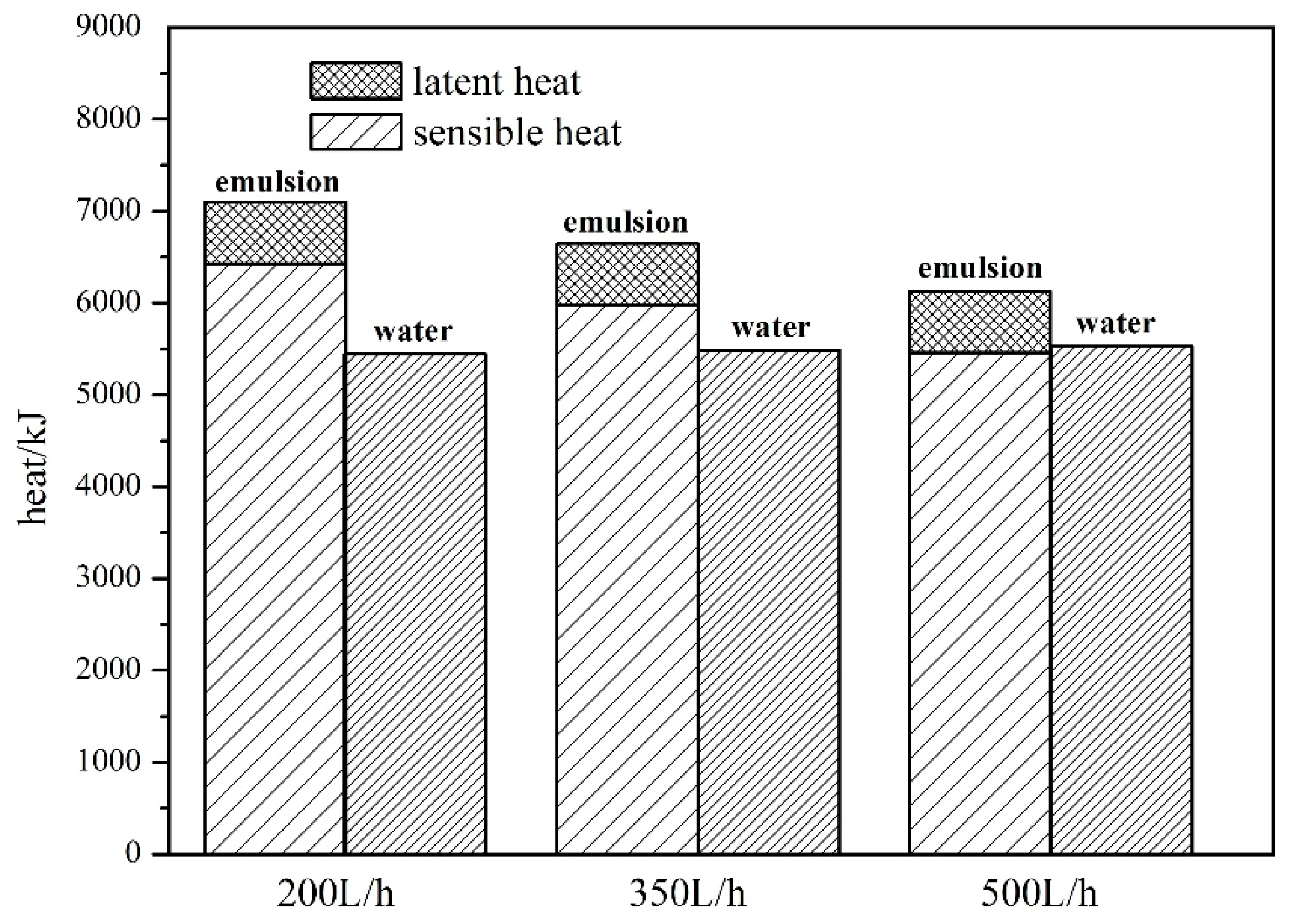
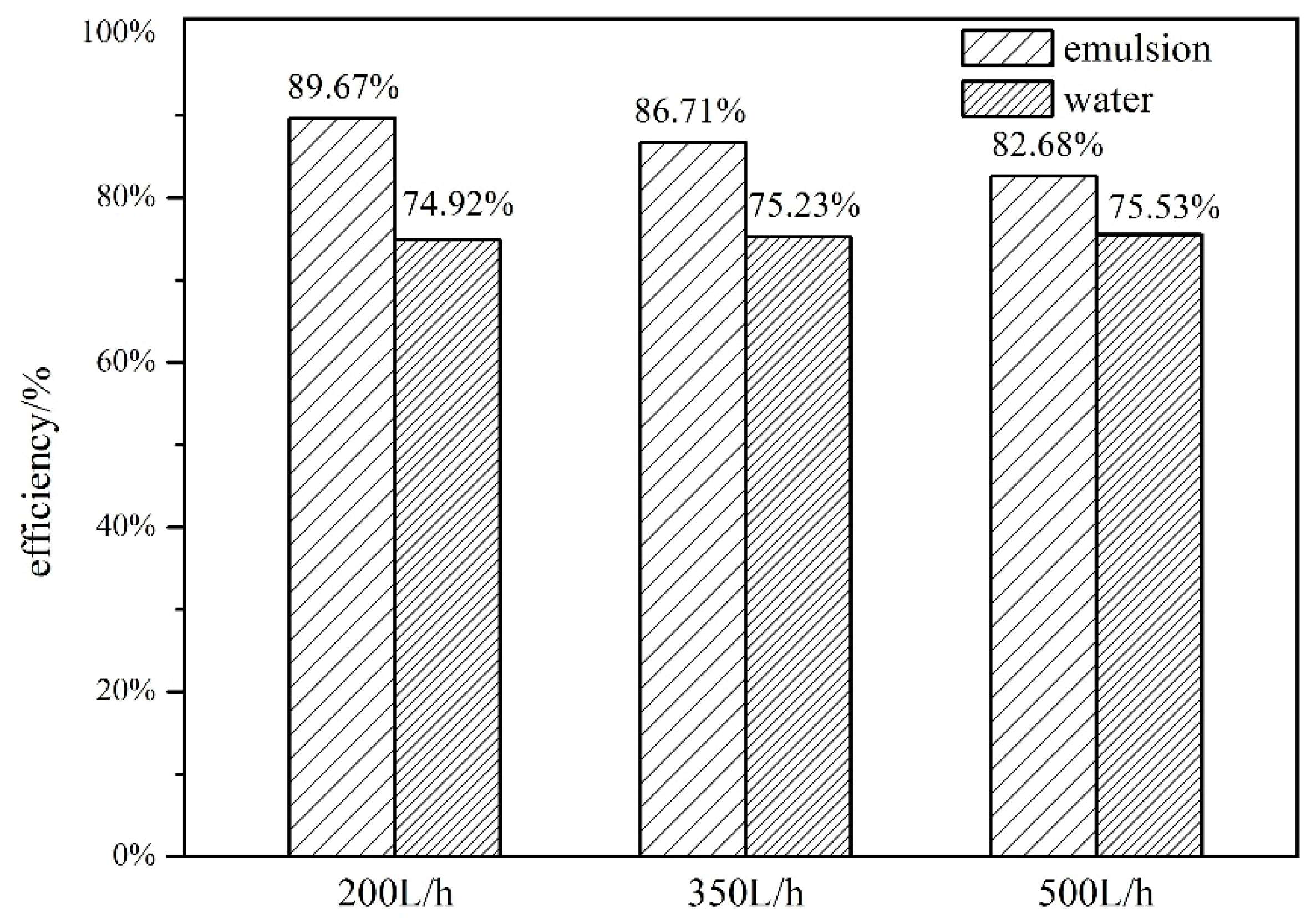
When the radiation is 800 W/m2, the thermal efficiency of different fluids under varied flow rates are shown in Figure 16. It is found that the sensible heat storage of the SWH-PCM system decreases with the increase of the flow rate, while the sensible heat storage of the SWH system is basically unchanged. The final fluid temperatures in the heat storage tank are all above 69 °C, thus the paraffin particles melt completely and the latent heat storage is 670.25 kJ. When the flow rate is 200 L/h, 350 L/h and 500 L/h, the sensible heat storage of the SWH-PCM system is 6429.0 kJ, 5974.75 kJ, 5455.54 kJ, and the heat storage of the SWH system is 5447.06 kJ, 5485.62 kJ, 5527.53 kJ respectively. In low flow rates (200 L/h and 350 L/h), the sensible heat and the total heat of the SWH-PCM system are all higher than those of the SWH system. While the flow rate increases to 500 L/h, the sensible heat of SWH-PCM system is slightly less than that of the SWH system. Because of the existence of the latent heat storage, the total heat storage is still higher than the SWH system.
The corresponding thermal efficiency is indicated in Figure 17. With the increase of the flow rate, the change trend of the thermal efficiency of SWH-PCM system is consistent with that of heat storage. As the flow rate increases from 200 L/h to 500 L/h, the thermal efficiency of the SWH system only increases by 0.61%, while the thermal efficiency of the SWH-PCM system decreased by 7.0%. However, the thermal efficiency of SWH-PCM system is higher than that of the SWH system, with the maximum value of 14.76% under the flow of 200 L/h.
5. Conclusions
In this paper, thermal performance comparison of the SWH-PCM system and SWH system was carried out through the experiment. The effect of solar irradiance and flow rate on the thermal performance of the two systems is also investigated experimentally. Research findings are listed as follows:
- (1)
- The SWH-PCM system has a higher temperature rising rate than that of the SWH before all paraffin particles melt into liquid. When the melting process has finished, the SWH-PCM system shows a similar temperature change trend as the SWH system. The SWH-PCM system obtains more heat storage than the SWH system
- (2)
- The heat storage of SWH-PCM system and SWH system all increase with the increase of solar irradiance, while the thermal efficiency has the opposite trend. The thermal efficiency of SWH-PCM system can achieve the maximum value of 90.40% as the solar irradiance of 500 W/m2.
- (3)
- As flow rates increase, the thermal efficiency of the SWH-PCM system decreases slightly, while the thermal efficiency of the SWH system basically is unchanged. The thermal efficiency of the SWH-PCM system can reach up to 89.67% with the flow rate of 200L/h, which is 14.76% higher than that of the SWH system.
In conclusion, graphene composite paraffin emulsion, used as a heat transfer medium in the solar water heating system, can effectively enhance the thermal efficiency, because the specific heat is significantly enhanced in the phase-transition region. However, the viscosity of the emulsion is much higher than that of water. Consequently, the pressure drops, and pumping power consumption should be considered for evaluating the performance of the emulsion in further investigations.
Author Contributions
Experiment, N.X. and L.S.; methodology, Y.Y.; investigation, L.S. and X.C.
Funding
This research was funded by the National Natural Science Foundation of China, grant number 51808453; China Postdoctoral Science Foundation, grant number 2018M633399 and Sichuan Science and Technology Support Program, grant number 2017GZ0389.
Conflicts of Interest
The authors declare no conflict of interest.
References
- Philibert, C. Barriers to Technology Diffusion: The Case of Solar Thermal Technologies; International Energy Agency: Paris, France, 2006. [Google Scholar]
- Boyle, G. Renewable Energy: Power for a Sustainable Future, 3rd ed.; Oxford University Press: Oxford, UK, 2012. [Google Scholar]
- Abhat, A. Low temperature latent thermal energy storage system: Heat storage materials. Sol. Energy 1983, 30, 313–332. [Google Scholar] [CrossRef]
- Regin, A.F.; Solanki, S.C.; Saini, J.S. Heat transfer characteristics of thermal energy storage system using PCM capsules: A review. Renew. Sustain. Energy Rev. 2008, 12, 2438–2458. [Google Scholar] [CrossRef]
- Zhang, Z.L.; Yuan, Y.P.; Zhang, N.; Sun, Q.R.; Cao, X.L.; Sun, L.L. Thermal properties enforcement of carbonate ternary via lithium fluoride: A heat transfer fluid for concentrating solar power systems. Renew. Energy 2017, 111, 523–531. [Google Scholar] [CrossRef]
- Qiu, Z.Z.; Ma, X.L.; Li, P.; Zhao, X.D.; Wright, A. Micro-encapsulated phase change material (MPCM) slurries: Characterization and building applications. Renew. Sustain. Energy Rev. 2017, 77, 246–262. [Google Scholar] [CrossRef]
- Wang, Z.Y.; Qiu, F.; Yang, W.S.; Zhao, X.D. Applications of solar water heating system with phase change material. Renew. Sustain. Energy Rev. 2015, 52, 645–652. [Google Scholar] [CrossRef]
- Ma, F.; Chen, J.; Zhang, P. Experimental study of the hydraulic and thermal performances of nano-sized phase change emulsion in horizontal mini-tubes. Energy 2018, 149, 944–953. [Google Scholar] [CrossRef]
- Zou, D.Q.; Feng, Z.P.; Xiao, R.; Qin, K.; Zhang, J.J.; Song, W.J.; Tu, Q. Preparation and flow characteristic of a novel phase change fluid for latent heat transfer. Sol. Energy Mater. Sol. Cells 2010, 94, 2292–2297. [Google Scholar] [CrossRef]
- Ni, L.; Qv, D.H.; Wang, J.J.; Shang, R.X.; Yao, Y. Forced convective heat transfer for laminar flow of paraffin: A numerical and experimental study. Appl. Therm. Eng. 2017, 113, 1152–1163. [Google Scholar] [CrossRef]
- Saarinen, S.; Puupponen, S.; Meriläinen, A.; Joneidi, A.; Seppälä, A.; Saari, K.; Nissila, T.A. Turbulent heat transfer characteristics in a circular tube and thermal properties of n-decane-in-water nanoemulsion fluids and micelles-in-water fluids. Int. J. Heat Mass Transf. 2015, 81, 246–251. [Google Scholar] [CrossRef]
- Meriläinen, A.; Seppälä, A.; Saari, K.; Seitsonen, J.; Ruokolainen, J.; Puisto, S.; Rostedt, N.; Nissila, T.A. Influence of particle size and shape on turbulent heat transfer characteristics and pressure losses in water-based nanofluids. Int. J. Heat Mass Transf. 2013, 61, 439–448. [Google Scholar] [CrossRef]
- Xie, H.Q.; Li, Y.; Yu, W. Intriguingly high convective heat transfer enhancement of nanofluid coolants in laminar flows. Phys. Lett. A 2010, 374, 2566–2568. [Google Scholar] [CrossRef]
- Morimoto, T.; Kumano, H. Flow and heat transfer characteristics of phase change emulsions in a circular tube: Part 2. Turbulent flow. Int. J. Heat. Mass Transf. 2018, 117, 903–911. [Google Scholar] [CrossRef]
- Wang, Z.Y.; Zhang, J.; Wang, Z.X.; Yang, W.S.; Zhao, X.D. Experimental investigation of the performance of the novel HP-BIPV/T system for use in residential buildings. Energy Build. 2016, 130, 295–308. [Google Scholar] [CrossRef]
- Serale, G.; Baronetto, S.; Goia, F.; Perino, M. Characterization and energy performance of a slurry PCM-based solar thermal collector: A numerical analysis. Energy Procedia 2014, 48, 223–232. [Google Scholar] [CrossRef]
- Qiu, Z.Z.; Ma, X.L.; Zhao, X.D.; Li, P.; Samira, A. Experimental investigation of the energy performance of a novel micro-encapsulated phase change material (MPCM) slurry based PV/T system. Appl. Energy 2016, 165, 260–271. [Google Scholar] [CrossRef]
- Zhao, Z.; Wu, T.; Shi, Y.; Li, L. An investigation on rheology and heat transfer characteristics for a phase change emulsion. J. Eng. Thermophys. 2001, 22, 589–592. [Google Scholar]
- Mikkola, V.; Puupponen, S.; Saari, K.; Ala-Nissila, T.; Seppälä, A. Thermal properties and convective heat transfer of phase changing paraffin nanofluids. Int. J. Therm. Sci. 2017, 117, 163–171. [Google Scholar] [CrossRef] [Green Version]
- Wang, F.; Liu, J.; Fang, X.; Zhang, Z. Graphite nanoparticles-dispersed paraffin/water emulsion with enhanced thermal-physical property and photo-thermal performance. Sol. Energy Mater. Sol. Cells 2016, 147, 101–107. [Google Scholar] [CrossRef]
- Xiang, N.; Yuan, Y.P.; Sun, L.L.; Cao, X.L.; Zhao, J. Simultaneous decrease in supercooling and enhancement of thermal conductivity of paraffin emulsion in medium temperature range with graphene as additive. Thermochim. Acta 2018, 664, 16–25. [Google Scholar] [CrossRef]
Figure 1.
The specific heat change trend during the melting process.
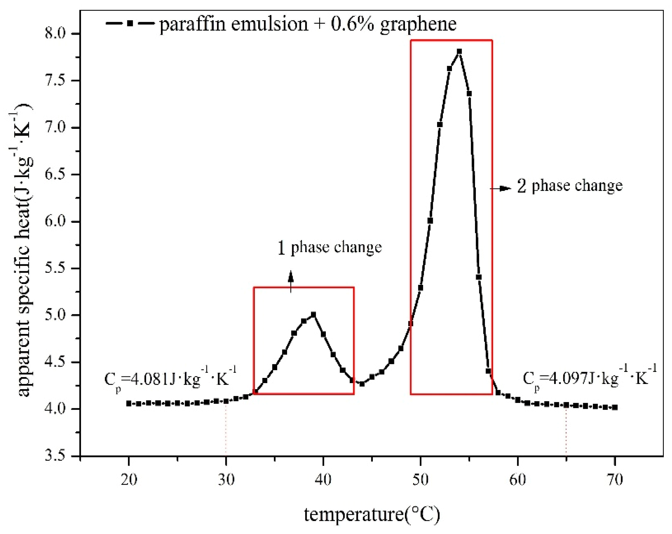
Figure 2.
Schematic diagram and picture of Solar water heating system. (a) Schematic diagram; (b) picture.
Figure 2.
Schematic diagram and picture of Solar water heating system. (a) Schematic diagram; (b) picture.


1- Heat storage tank; 2- Centrifugal pump; 3-Flowmeter; 4- Solar collector; 5- Total radiometer;
6- Solar radiation simulator; 7-Data acquisition; 8- Stirring apparatus
Figure 3.
Structure of the solar collector.

Figure 4.
Temperature distribution in the vertical direction of the thermal storage tank. (a) Solar water heating-phase change material (SWH-PCM) system; (b) Solar water heating (SWH) system.
Figure 4.
Temperature distribution in the vertical direction of the thermal storage tank. (a) Solar water heating-phase change material (SWH-PCM) system; (b) Solar water heating (SWH) system.

Figure 5.
Comparison of ambient temperature and solar radiation.

Figure 6.
Outlet temperature of the solar collector.

Figure 7.
Average heat storage in different temperature ranges.

Figure 8.
The average temperature curve of the tank.

Figure 9.
Outlet temperature of the solar collector under different radiations.

Figure 10.
Regional average heat of the SWH-PCM system under different radiations.
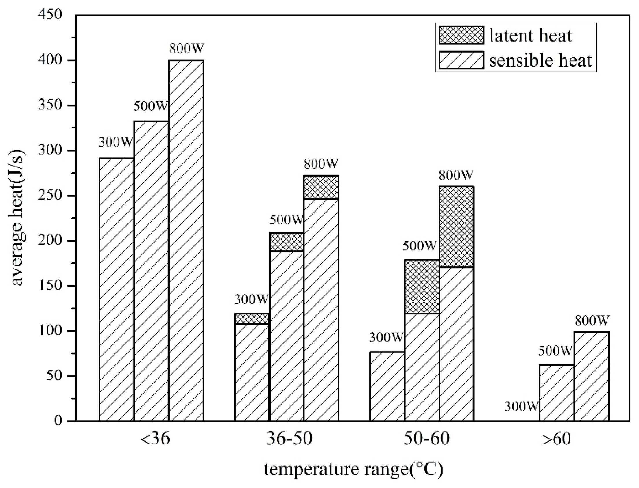
Figure 11.
Temperature curves of the storage tank under different radiations.
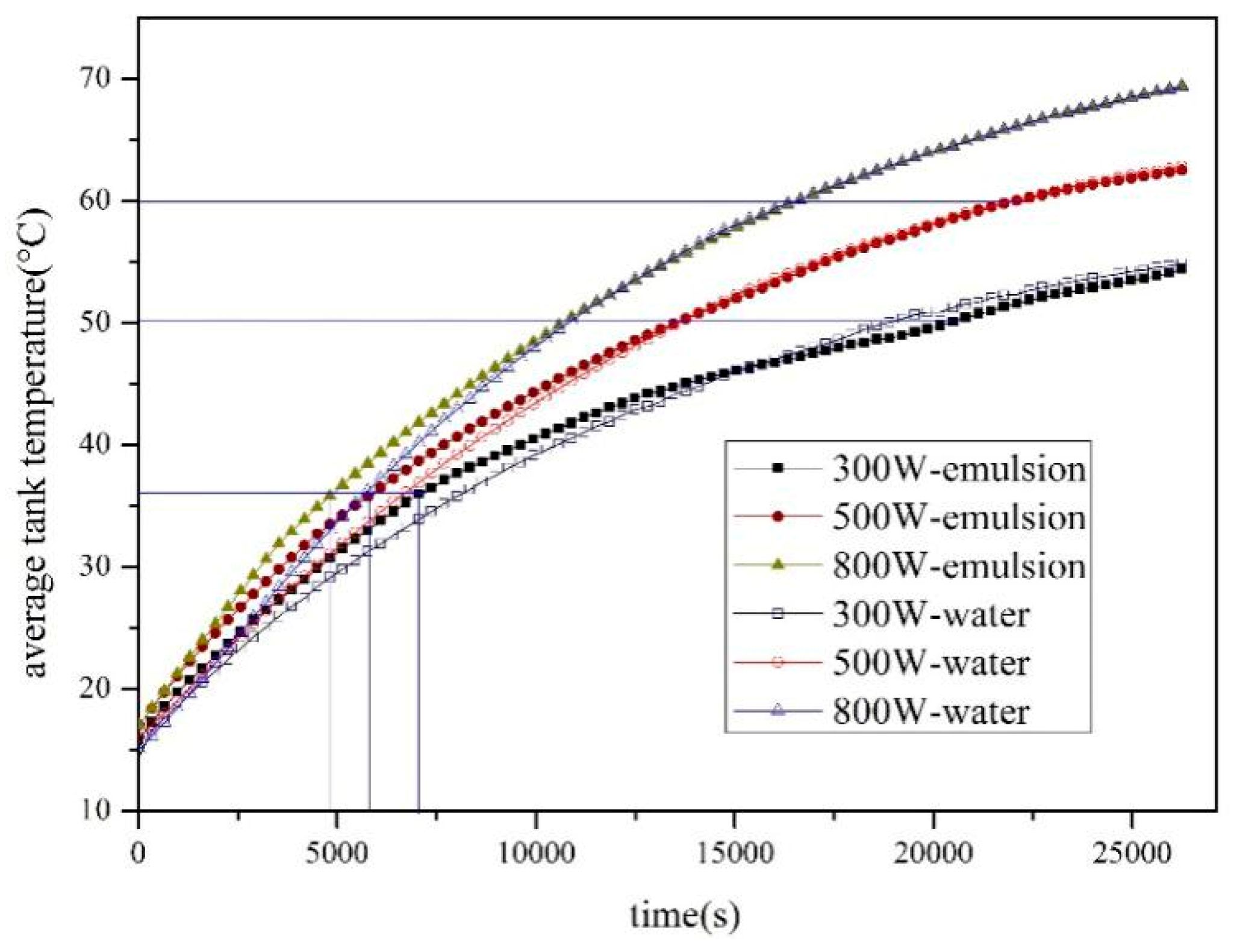
Figure 12.
Collector outlet temperature curves under different flow rates. (a) SWH-PCM system; (b) SWH system.
Figure 12.
Collector outlet temperature curves under different flow rates. (a) SWH-PCM system; (b) SWH system.

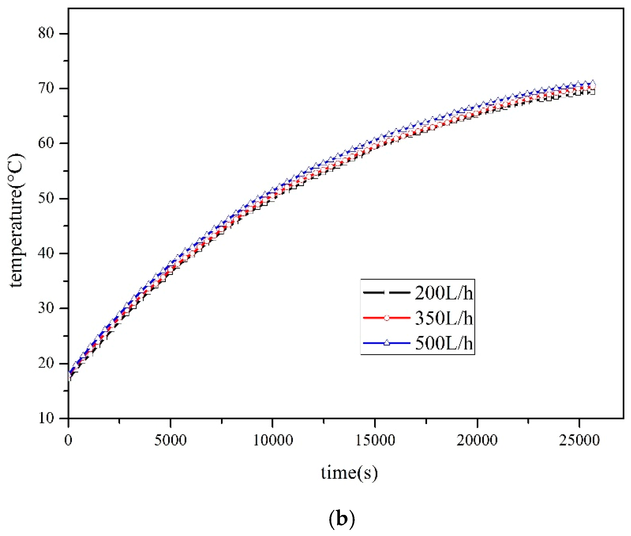
Figure 13.
The regional average heat of the SWH-PCM system under different flow rates.

Figure 14.
Heat storage under different radiations.

Figure 15.
Thermal efficiency under different radiations.
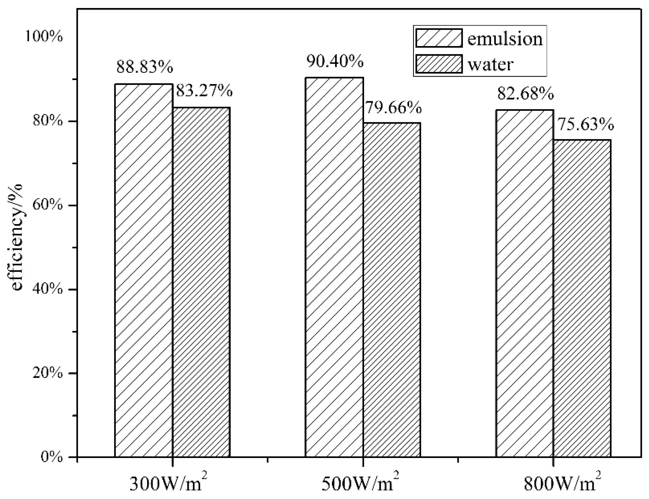
Figure 16.
Heat storage under different flow rates.

Figure 17.
Thermal efficiency under different flow rates.


Table 1.
Performance parameters of graphene composite paraffin emulsion.
| Performance Parameters | Process | Phase Change Temperature/°C | Phase Change Enthalpy/kJ·kg−1 | Thermal Conductivity/W·m−1·K−1 | Super Cooling/°C | Viscosity/Pa·s | |
|---|---|---|---|---|---|---|---|
| Graphene composite paraffin emulsion (0.6%wt graphene, 20%wt paraffin emulsion) | Melting | 1 | 36.0 | 6.23 | 0.472(30 °C) | 2.13 | 0.438– 0.00615 (30 °C–60 °C) |
| 2 | 50.4 | 20.58 | |||||
| Solidification | 56.48 | 25.51 | |||||
Table 2.
Measuring range and accuracy.
| Parameter | Measurement Equipment |
|---|---|
| Temperature | K-type thermocouples range: −200–1300 °C, accuracy: ±0.2 °C |
| Flow rate | LYDF-DN10 electromagnetic flowmeter range: 30–600 L/h, accuracy: 0.5% |
| Solar radiation (Ambient temperature) | Delta-T SPN1 pyranometer range: 0–2000 W/m2, accuracy: ±5 W/m2 (range: −40–80 °C, accuracy: ±0.4 °C) |
Table 3.
Parameters of the solar collector.
| Layer | Parameter | Value |
|---|---|---|
| Covering glass | Thickness | 5 mm |
| Material | Tempered glass | |
| Air layer | Thickness | 20 mm |
| Vacuum coating | length × width × thickness | 1050 × 514 × 2 mm |
| Thermal conductive silica gel | Thickness | 2 mm |
| Thermal conductivity coefficient | 1.2 W/(m·K) | |
| Absorber plate | Material | Copper |
| Thickness | 2 mm | |
| Absorbent film | material | Blue titanium |
| thickness | 0.2 mm | |
| absorptance | 95% | |
| Tube | Material Diameter | Copper 12 mm |
| Distance of adjacent tubes | 70 mm | |
| Insulation material | Material | Rock wool |
| Thickness | 40 mm | |
| Thermal conductivity coefficient | 0.039 W/(m·K) |
© 2019 by the authors. Licensee MDPI, Basel, Switzerland. This article is an open access article distributed under the terms and conditions of the Creative Commons Attribution (CC BY) license (http://creativecommons.org/licenses/by/4.0/).
Share and Cite
MDPI and ACS Style
Sun, L.; Xiang, N.; Yuan, Y.; Cao, X. Experimental Investigation on Performance Comparison of Solar Water Heating-Phase Change Material System and Solar Water Heating System. Energies 2019, 12, 2347. https://doi.org/10.3390/en12122347
AMA Style
Sun L, Xiang N, Yuan Y, Cao X. Experimental Investigation on Performance Comparison of Solar Water Heating-Phase Change Material System and Solar Water Heating System. Energies. 2019; 12(12):2347. https://doi.org/10.3390/en12122347
Chicago/Turabian StyleSun, Liangliang, Nan Xiang, Yanping Yuan, and Xiaoling Cao. 2019. "Experimental Investigation on Performance Comparison of Solar Water Heating-Phase Change Material System and Solar Water Heating System" Energies 12, no. 12: 2347. https://doi.org/10.3390/en12122347
Note that from the first issue of 2016, this journal uses article numbers instead of page numbers. See further details here.