Large Scale Renewable Energy Integration: Issues and Solutions
by
 , , and
G. V. Brahmendra Kumar
1 ,
,
Ratnam Kamala Sarojini
1,
K. Palanisamy
1,*,
Sanjeevikumar Padmanaban
2,* and
and
Jens Bo Holm-Nielsen
2 1
School of Electrical Engineering, Vellore Institute of Technology, Vellore 632014, India
2
Center for Bioenergy and Green Engineering, Department of Energy Technology, Aalborg University, 6700 Esbjerg, Denmark
*
Authors to whom correspondence should be addressed.
Energies 2019, 12(10), 1996; https://doi.org/10.3390/en12101996
Submission received: 16 April 2019
/
Revised: 17 May 2019
/
Accepted: 21 May 2019
/
Published: 24 May 2019
(This article belongs to the Special Issue Power Electronic Converter Configuration and Control for DC Microgrid Systems)
Abstract
:In recent years, many applications have been developed for the integration of renewable energy sources (RES) into the grid in order to satisfy the demand requirement of a clean and reliable electricity generation. Increasing the number of RES creates uncertainty in load and power supply generation, which also presents an additional strain on the system. These uncertainties will affect the voltage and frequency variation, stability, protection, and safety issues at fault levels. RES present non-linear characteristics, which requires effective coordination control methods. This paper presents the stability issues and solutions associated with the integration of RES within the grid.
1. Introduction
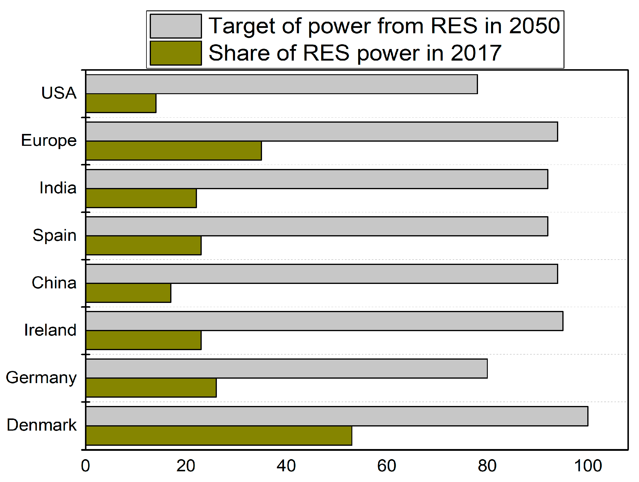
The majority of countries across the world are concentrating on RES, due to an increase of environmental concerns and depletion of fossil fuels [1]. For example, China is aiming for RES to represent somewhere around 35 percent of consumption by 2030. India has set an ambitious RES target of 175 GW [2]. The European Union and the United States also have targets regarding RES [3]. Some countries successfully integrated large shares of RES in the power grid in 2017, and most countries have set targets to receive their power generation from RES by 80% in 2050, as is shown in Figure 1.
Due to the irregularities and fluctuating features of RES, new challenges to the grid over a unified anticipated generation have been created. The RES outputs are influenced by meteorological conditions. These characteristics affect the power system efficacy, power quality, system reliability, load management, security, and safety in various ways and are also very significant factors to be viewed in the integration of RES within the grid [6]. This influence is commonly observed with solar and wind energy, but geothermal, hydropower and biomass energy resources are more anticipated and have irrelevant difficulties in their association with the grid [7]. The comparison of RES with a synchronous generator (SG) is shown in Table 1.
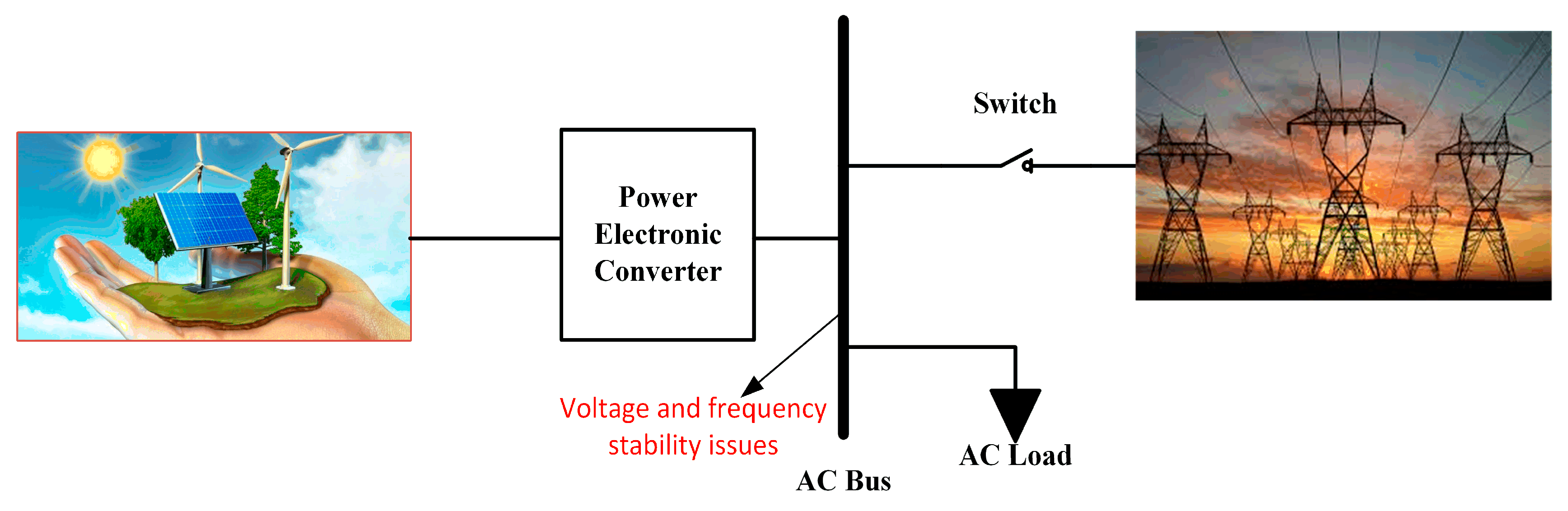
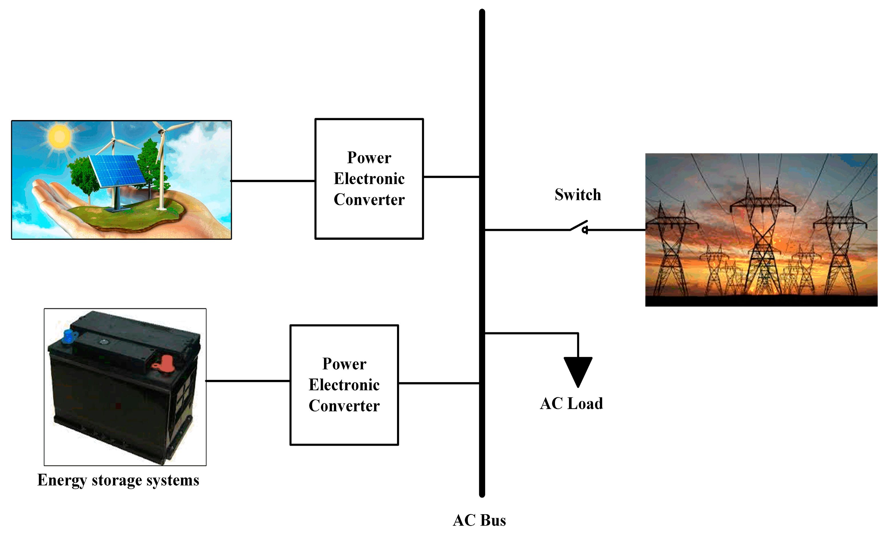
The RES integrated with the grid is shown in Figure 2. Figure 2 is incorporated with RES, grid and electronic components. The power generation from RES to the grid is unidirectional. The RES requires the converters to be connected to the grid. These converters will achieve efficient operation and obtain the energy quality requirements related to the harmonics level. Also, this allows the integration of RES in a power inverter with high energy features and safety.
The remainder of this paper is organized as follows: Section 2 considers the grid integration issues with a high share of RES, and solutions for variable RES is discussed in Section 3. The Energy Storage System (ESS) support is explained in Section 4, and followed by smart grid features in voltage control with RES in Section 5. Section 6 is the conclusion.
2. Grid Integration Issues with a High Share of RES
As the power generation from RES increases, the installed capacity of power converters increases. By utilizing the large scale of solar energy, the RES system is able to supply power to the grid. Thus, by increasing the capacity of the RES, the grid-connected RES will create a negative impact on the grid when fault or disturbance occurs. Hence, the Point of Common Coupling (PCC) voltage drop is triggered by a fault in grid power and the RES will become off-grid across a wide area range. Moreover, these fault impacts cause the grid voltage and frequency collapse, also affecting the safe, stable and reliable operation of the grid and even triggering large economic losses [8].
2.1. Impact of Large-Scale Integration of RES on Frequency
The frequency of a power system must be preserved near to its nominal value (either 50 Hz or 60 Hz based on the grid). The frequency deviations will only arise when there is a mismatch between generation and load. A stiff power system preserves the frequency subsequent to a contingency event [9].
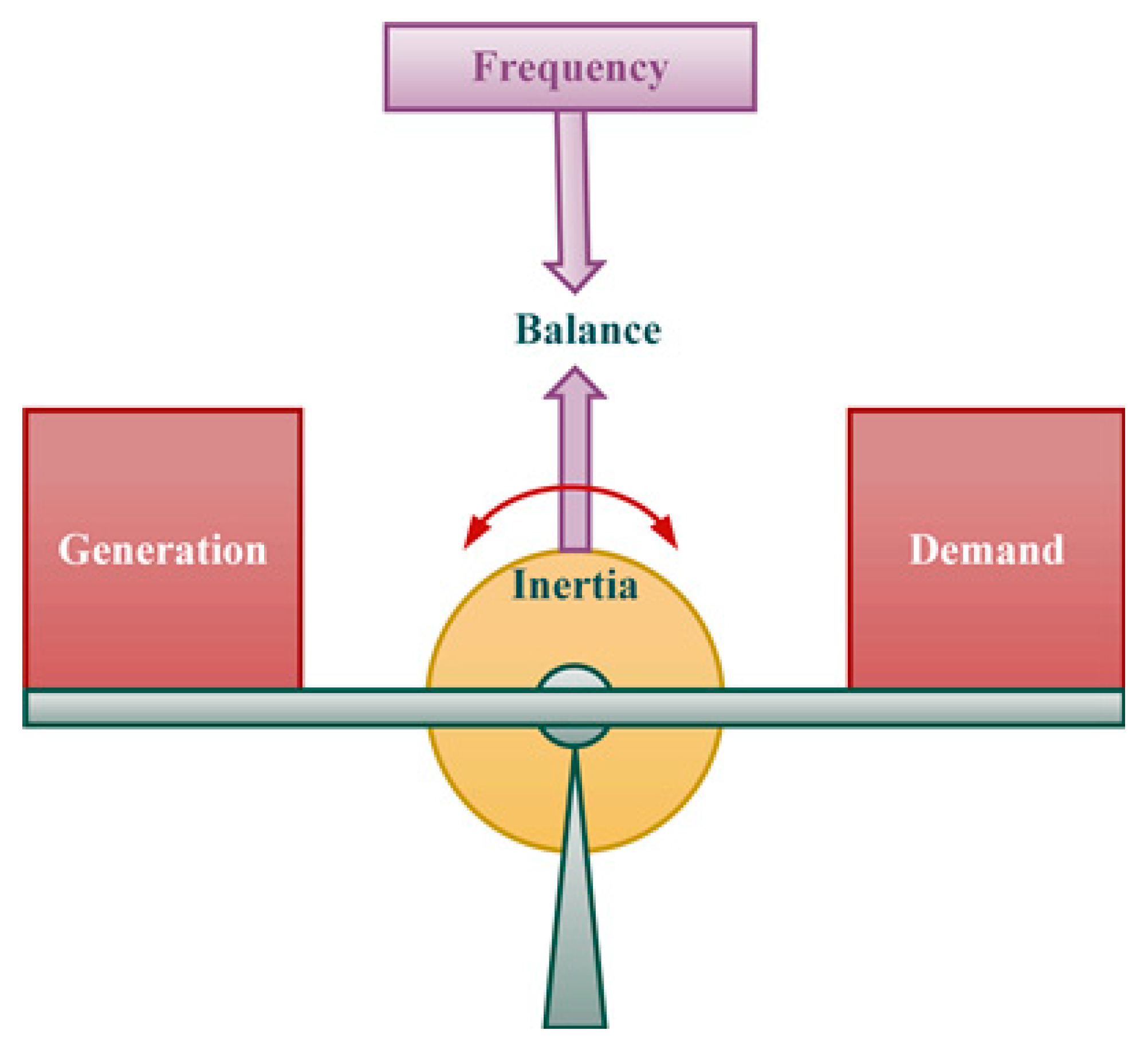
The frequency of the power system is maintained at the nominal value only when the active power of generation and demand is balanced as indicated in Figure 3. If the demand is more than the generation, then the frequency decreases from the nominal value. In the case of surplus generation, the system frequency increases. The kinetic energy (KE) stored in the rotor of the rotating machines present in the power system contribute to inertia. The inertia in the power system regulates the frequency in demand generation imbalances. If the inertia is more in the power system, then it is less sensitive to small power imbalances. The inertia in the power system provides energy for some time to reduce the frequency deviations.
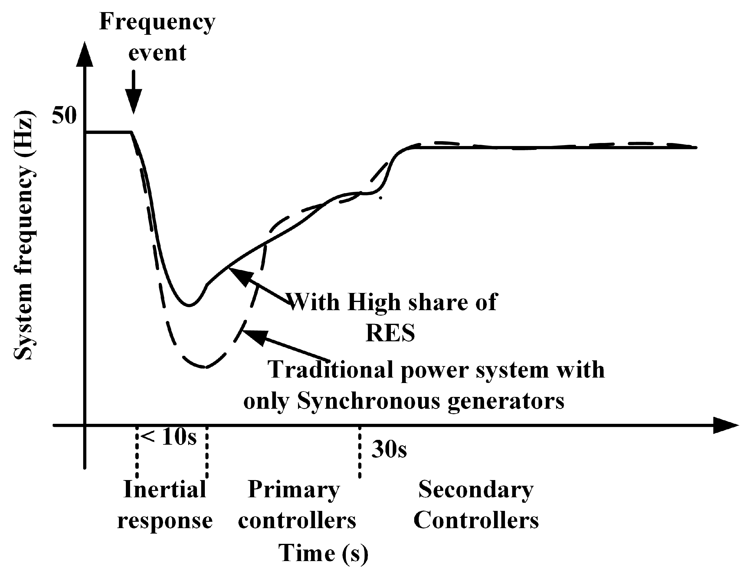
In order to balance the power generation and demand, several control techniques are employed in a power system in multiple time frames as shown in Figure 4. The frequency response of a power system is comprised of the following steps [10]:
- Inertial response (a few seconds).
- Primary frequency response—Governor Response (1–10 s).
- Secondary frequency response—Area Governor Control response (seconds to minutes).
When the power imbalance occurs, the frequency starts to fall. The Rate of Change of Frequency (ROCOF) is more at the initial stage. ROCOF is associated with how much inertia is present in the system; the inertia slows down the initial frequency deviation, and this is called the inertial frequency response. The governor response is the primary frequency technique which acts within the first few seconds (typically 10–30 s) after a frequency event and seeks to reduce the frequency deviation. As the frequency reaches a minimum value (the frequency nadir); then the governor control is activated. Hence, the active power output increases and the frequency settles at a point slightly below the nominal value [11].
As the penetration level of RES increases, the frequency deviations are more frequent. As these RES are connected to the grid through a power electronic inverter, substituting the conventional SG with power electronic inverters will decrease the inertia of the power system. To handle the frequency stability issues raised from the low inertia and reserve power, new frequency control techniques need to be employed for RES to participate in a frequency regulation process.
2.2. Voltage Rise and Fluctuation
It is considered that electricity is distributed at the consumer’s terminal within the tolerable limit. The normal allowable voltage range is ±6% of the nominal value [12]. When large RES is integrated with lightly loaded feeders, the impact is unbearable. Whenever there is any change in load, the voltage fluctuation occurs at PCC. The voltage fluctuations and dips occur due to earth leakage faults and earth short-circuits located in the electrical power system (EPS). These faults weaken the voltage quality at PCC, based on fault situations. This is a significant element, particularly for solar and wind energy sources which possess irregular characteristics due to the wind speed disparity and solar irradiance that changes with time. The sensitivity of both electrical and electronic appliances that contributes to the life span deficiency of maximum devices is due to the voltage deviation [13].
Impact of RES on Voltage Drops in the Grid
Voltage is a significant factor in EPS. Hence, voltage control requirements are essential in EPS for both transmission and distribution levels. The source voltage and voltage drop at the feeder is determined at the end of the feeder [14]. The voltage drop in the feeder is due to the conductor impedance, current flow, and load. Also, the drop should not be lower when in a peak load situation, and it should not be more than the maximum voltage in a light load condition.
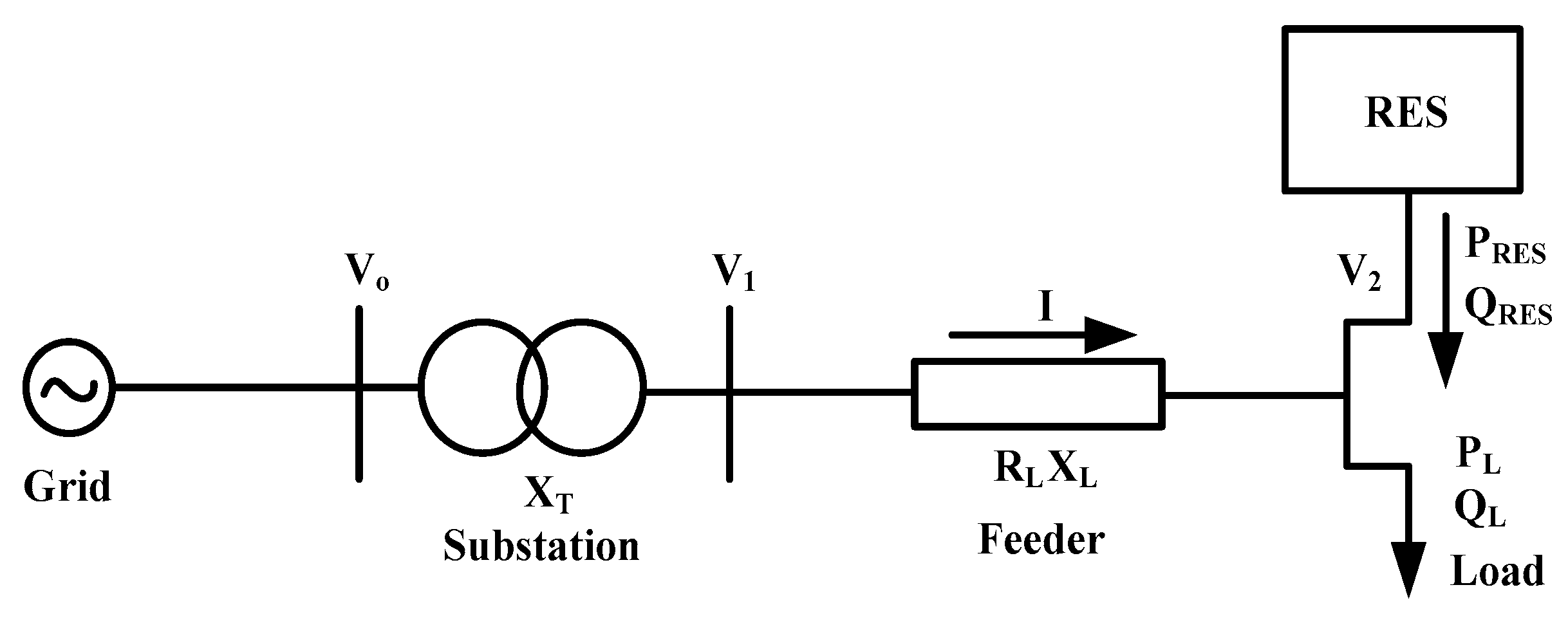
Equation (1) shows the injection of reactive power from RES within the grid; the RES will continually diminish the drop at the feeder. Where ΔV is the voltage between bus 1 & 2, P and Q are active and reactive power, and RLN & XLN are the line resistance and reactance, respectively. The grid is incorporated with RES and the load is shown in Figure 5. If the supply power is lower than the demand, the RES will inject power into the grid. Hence, this process is subject to RES active/reactive power that is relevant to the load active/reactive power and line X/R ratio [15].
3. Solutions for Variable RES
Various control techniques need to be employed to increase the power generation from RES and to decrease the negative impact of the RES on the power grid. This section gives a brief overview of the frequency and voltage control techniques for RES.
3.1. Frequency Control Techniques for RES
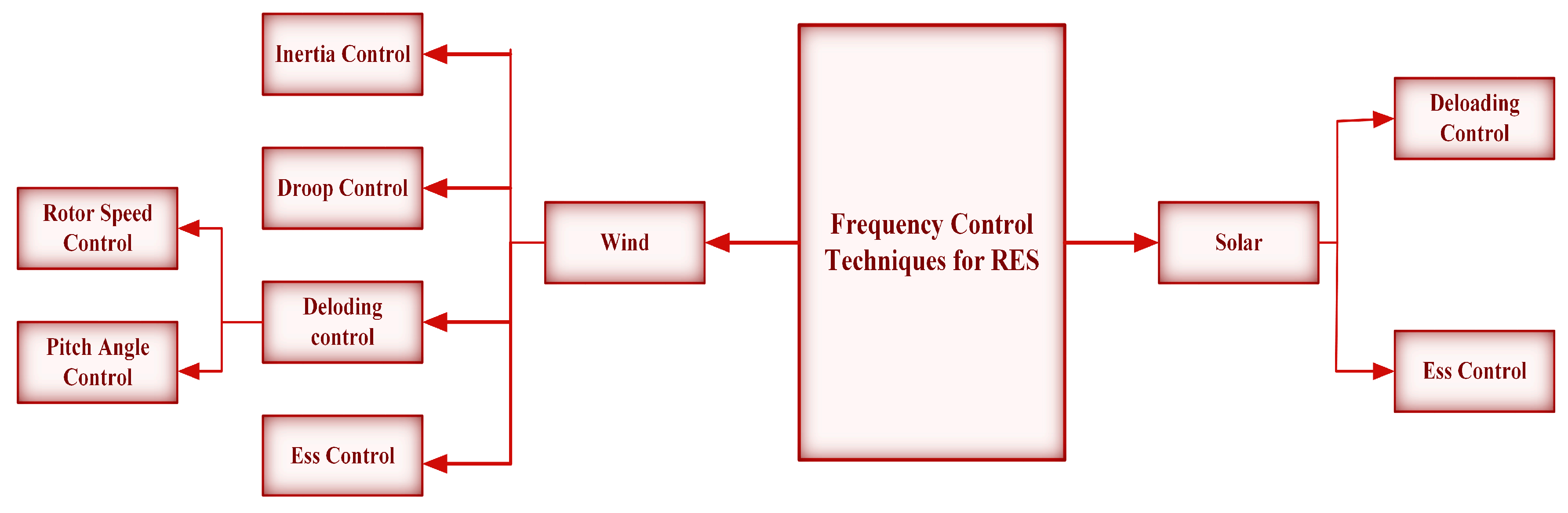
The frequency control techniques employed for RES are shown in Figure 6. The frequency control techniques used for both wind and solar are discussed in this section. For RES-based power plants, the frequency can be controlled by reserving the active power by using the de-load operation or by using the energy storage system (ESS). Generally, Inertia and frequency control methods for RES are categorized in two ways: control techniques to de-load the RES, and control practices for RES with ESS.
3.1.1. Control techniques Used for Wind Turbines
The frequency control techniques for the wind turbine can be classified in three ways, i.e., 1. Inertia control, 2. Droop control, 3. De-loading control.
3.1.2. Inertia Control
The inertia of the wind turbines needs to be emulated to maintain the frequency stability under the high penetration of wind power generators. The inertia of the wind turbines can be emulated by either “hidden” inertia emulation or by the fast power reserve emulation.
(a) Hidden inertia emulation
The emulation of hidden inertia present in the wind turbines is used to reduce the frequency deviation and to maintain the frequency stability. The suitable control algorithm for the power electronic converter for the wind turbines allows the wind turbine to release the KE stored in the rotating blades. The KE stored in the blades of the wind turbine helps to regulate the frequency under unbalance condition through its inertial response [16]. There are two ways to emulate the inertial response, either by considering the ROCOF alone or by incorporating both ROCOF and frequency deviation. Figure 7 shows the control diagram for the inertia emulation, considering only ROCOF to release the KE stored in the wind turbine. The inertia constant (H) is used to express the inertial characteristics. The “hidden” inertia of wind turbines can be known as,
where the inertia of the wind turbine is, is the VA rating of the machine, is the nominal angular frequency.
The inertial active power control signal of the hidden inertial emulation control is known as,
where the angular frequency of the system is, is the reference angular frequency.
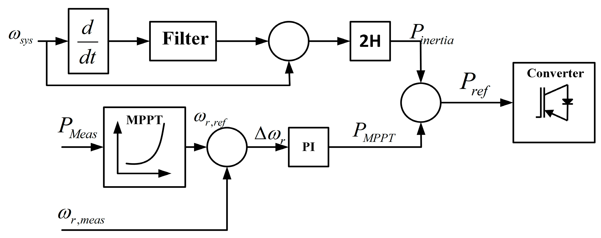
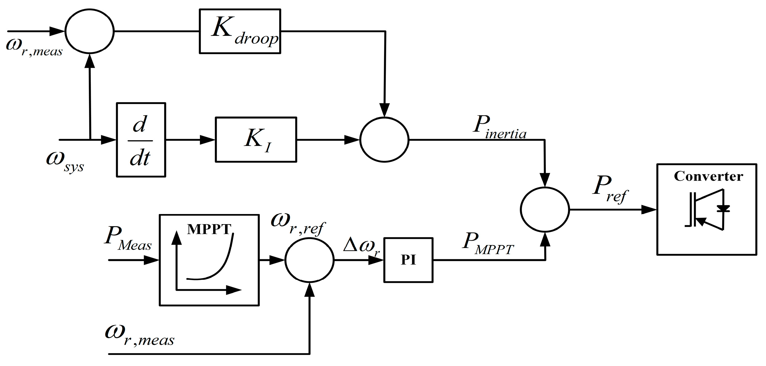
The inertia control algorithm with both ROCOF and frequency deviation is shown in Figure 8. In the power balanced condition, the active set power is monitored by the MPPT controller. Under power imbalance/frequency disturbance conditions the control algorithm acts and produces the extra inertial power signal. In this controller, the inertial power is calculated from both the ROCOF loop and frequency deviation loop. The inertial power calculated from the Figure 8 is known as,
where and are the inertia and drooping gains respectively.
The wind generators can store and release KE instantly compared to the SG, due to the power electronic converter controller. The variable speed wind turbines can participate more in the frequency regulation by releasing more KE than fixed speed wind turbines and SG [19].
(b) Fast Power Reserve
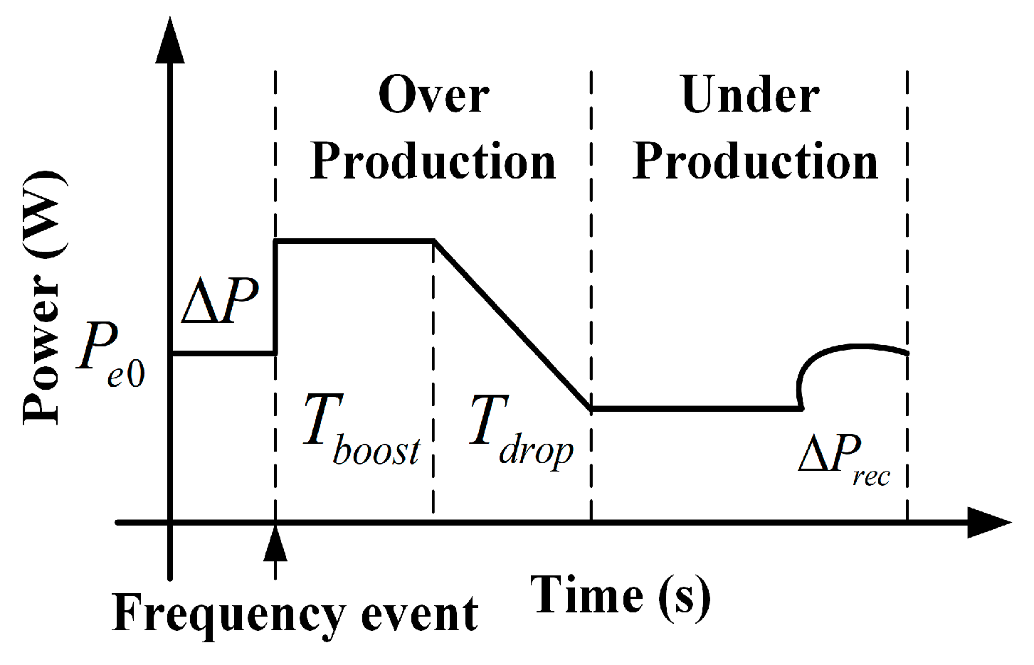
Usually, the emulated inertia for the wind turbines can be determined based on the frequency deviation or ROCOF, as illustrated in the above section. Whereas the fast power reserve is defined as the constant active power support regardless of the wind speed [16]. The fast power characteristics are shown in Figure 9. The fast power reserve is the temporary power, released from the KE stored in the rotating blades of the wind turbine.
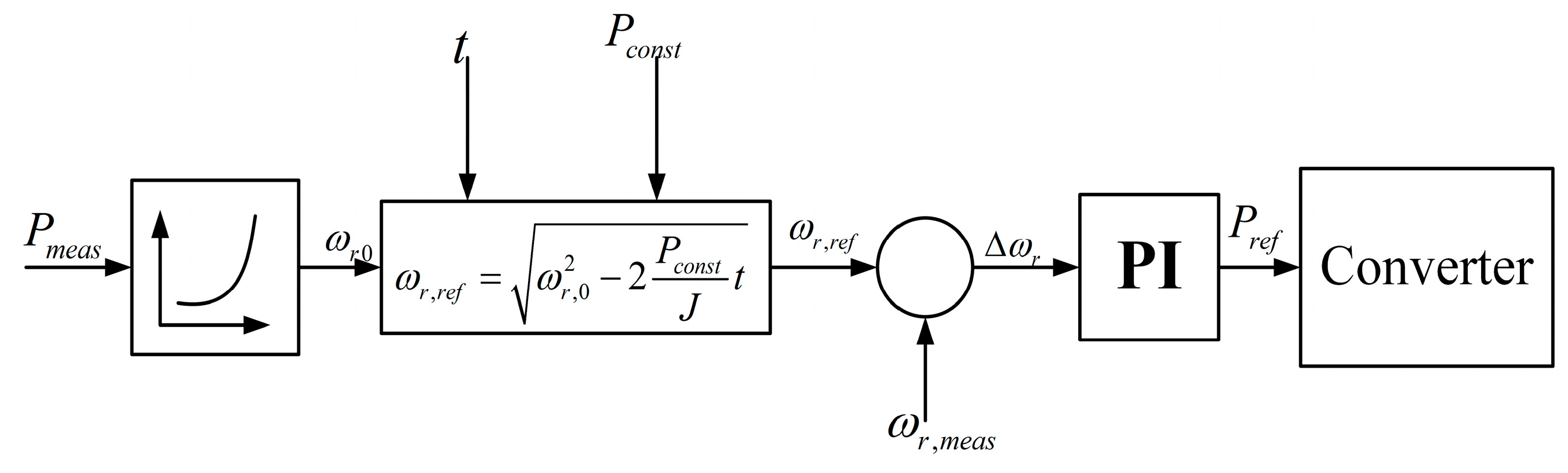
The control diagram of fast power reverse is shown in Figure 10. This fast power reserve can be realized by regulating the set value of the rotor speed. This is given by,
where t (t < tmax) is the lasting time of the fast power reserve since the beginning of the frequency event, is the rotor speed at the start and is the rotor speed at t, is the constant active power available at t, hence the refence angular speed in this method can be calculated as .
The fast power reserve control operates when the frequency deviation is more than the threshold value. This control delivers the extra power in the frequency event through the KE stored in the rotor and can be known as “over-production”. To recover the KE after the event is known as “under-production”. The shifting of an over-production state to an under-production state must be in a sloped manner, to avoid a sudden dip in the active power [20].
3.1.3. Droop Control for Frequency Regulation
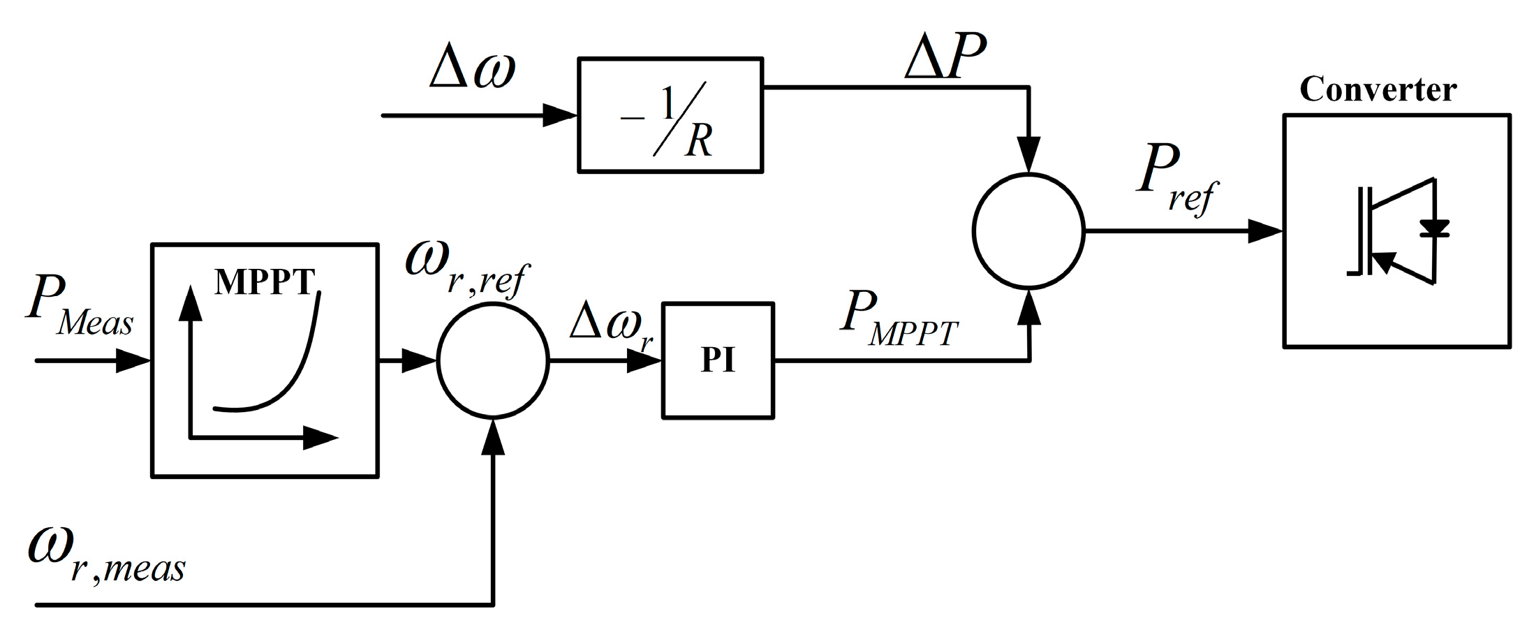
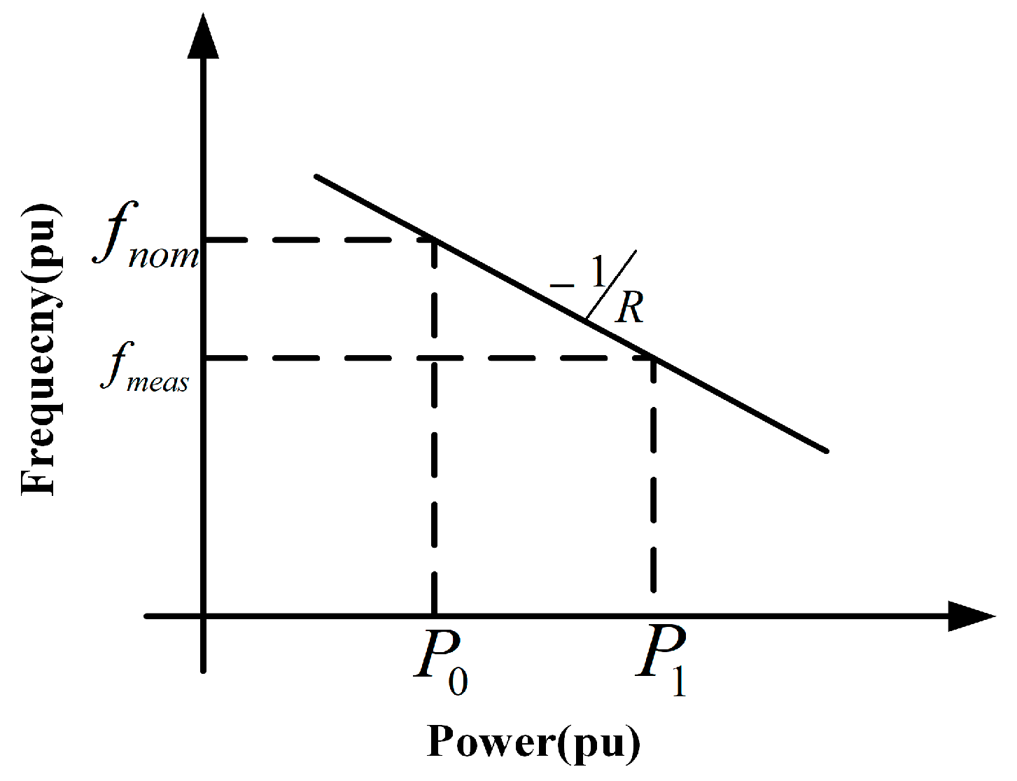
The droop control of a wind turbine adjusts the active power response based on the frequency deviation. The droop controller shown in Figure 11 decreases the frequency nadir. Regulated active power and frequency is linearly related and it is shown in Figure 12.
When the frequency drops from fref to fcal, the wind generator increases the output of power from P0 to P1 to regulate the frequency deviation. Hence, the active power regulated by the droop control can be given as,
where R is the droop coefficient, and are the measured frequency and wind turbine output power, respectively, while and are the initial operating points.
The analytical method for estimating the influence of inertia and droop responses from wind for frequency control was presented [21]. The droop control for wind turbine is shown in Figure 12. In order to use the wind turbine in frequency regulation under higher penetration, the adaptive gains for both the inertia, and droop controller was proposed in [22] by Yuan-Kang Wu. The inertia and droop gains are altered from time to time depending on the frequency imbalance.
3.1.4. De-Loaded Operation in Wind Turbines
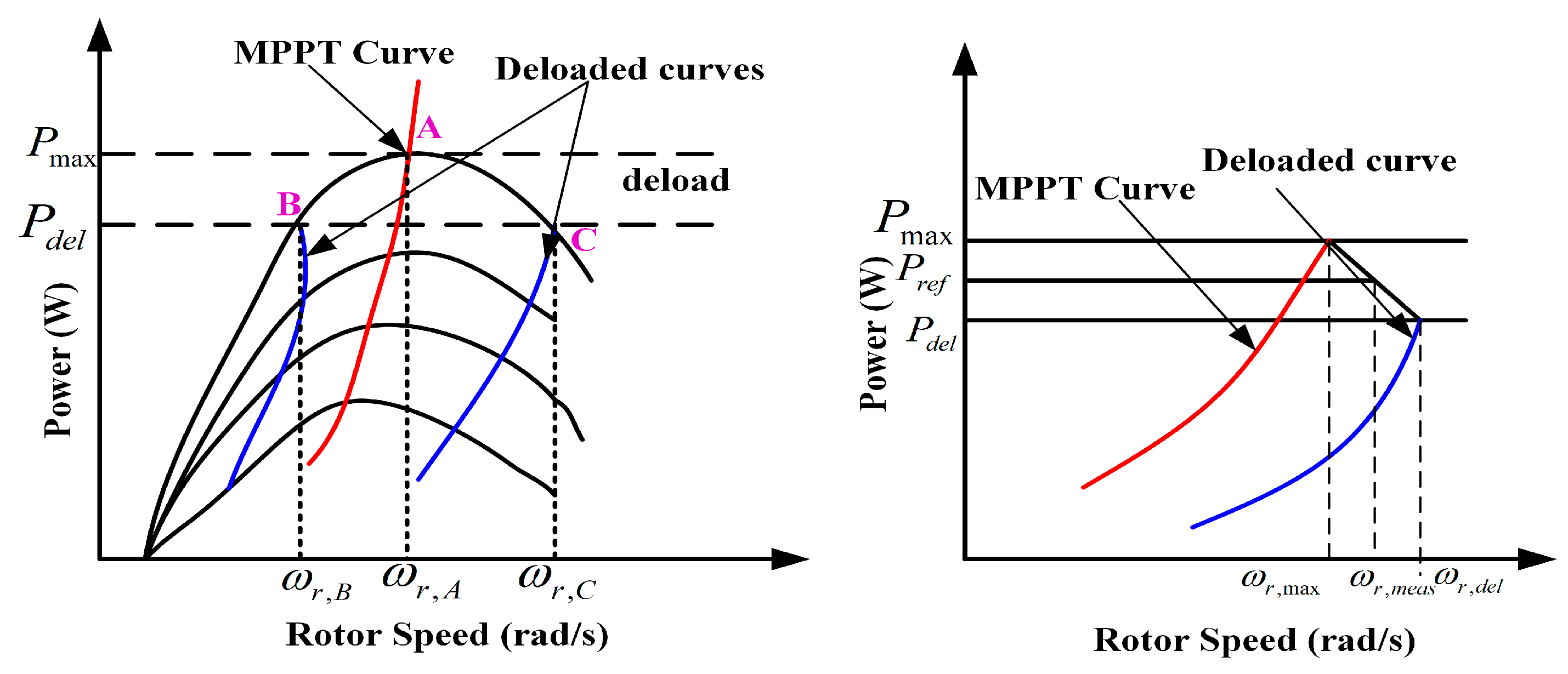
The control techniques presented in this section would help to eliminate the adverse impact of the higher RES penetration level on the frequency stability. This section addresses the inertia and frequency control techniques with the de-loaded operation of RES. The reserve power in RES-based generators from de-loaded operation can be utilized for the inertial response, and primary frequency support. Generally, the wind turbines are operated with a maximum power point tracking technique and this does not contribute to frequency regulation. To maintain the stability of the power system, the wind turbines need to participate in the frequency regulation with the increasing penetration level of wind in the power system. The de-loaded control techniques enable the wind turbines in frequency regulation. The de-loaded operation of wind generators for the fast frequency reserve was initially proposed in [23]. Some of the authors [9] proposed maintaining the active power reserve for high wind speeds, and the reserve being unavailable in lower wind speeds. Another way to maintain the reserve power for the wind generators is by de-loading them in low wind speeds. Although, the reserve is not available above the wind-rated speeds [24]. The author of [25,26,27,28] proposed the de-loaded operation of a wind generator over the entire speed range, either in lower wind speeds or in higher wind speeds. The power and rotor characteristics for the de-loaded operation of wind turbine are shown in Figure 13.
(a) Speed Control
The de-loading operation of the wind turbine can be realized by changing the operating point from the maximum power point (Pmpp) to a sub-optimal power point (PSuboptimal). The power can be varied from Psub to Pmpp by regulating the rotor speed. The speed control method controls the tip speed ratio (λ) and it is known as,
where the rotor radius and ν is is the velocity of wind.
By controlling the speed ratio () the operating point of the wind turbine can be altered and is shown in Figure 14.
Therefore, the reference power given for the wind turbine can be known as [29],
where is maximum power, is de-loaded power, is rotor speed at Pmax, is de-loaded rotor speed at .
In the rotor speed control of wind turbines, there are two different possibilities to regulate the active power output: over-speeding and under-speeding of the turbine. In case of over-speed mode, the wind turbine delivers the KE until the operating point has reached the maximum power point (). Whereas, in under-speed mode the wind turbine absorbs the KE until the operating point has reached the maximum power point [30]. The under-speeding of the rotor control results in stability problems. Hence, over-speeding of the rotor control is used.
The active power reference from Equation (9) uses a de-loaded power extraction curve shown in Figure 14. This technique regulates output of the active power from the wind turbine under a frequency event. Generally, the speed control technique is appropriate for low wind speeds.
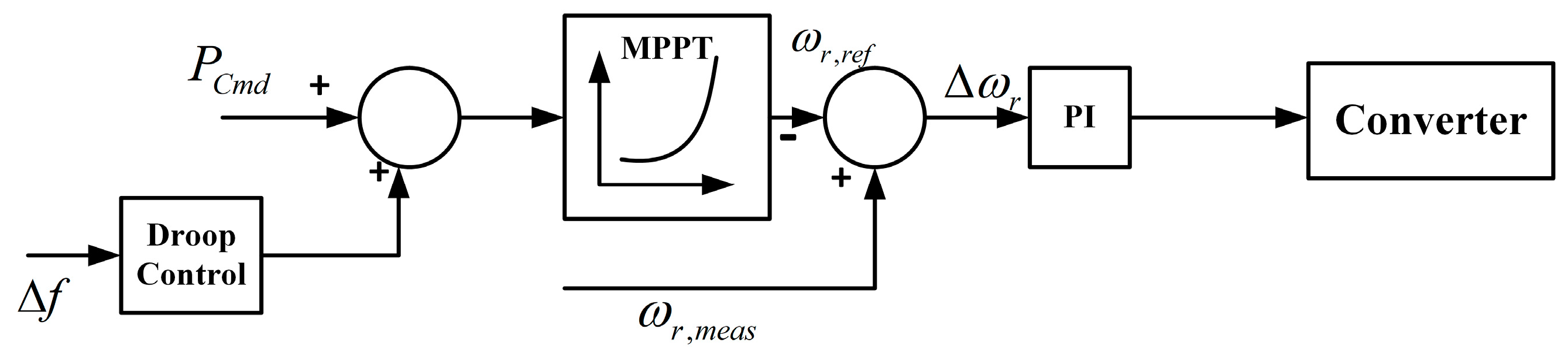
The rotor speed control of the wind turbine is presented in [23] and regulates the active power output under a frequency event. In this paper, the author utilized the optimum power extraction curve to regulate the active power of a wind turbine. The power transferred to the grid is dependent on the slip for a doubly-fed induction generator. If the slip is increased, then the power transferred from the wind generator to the grid is increased.
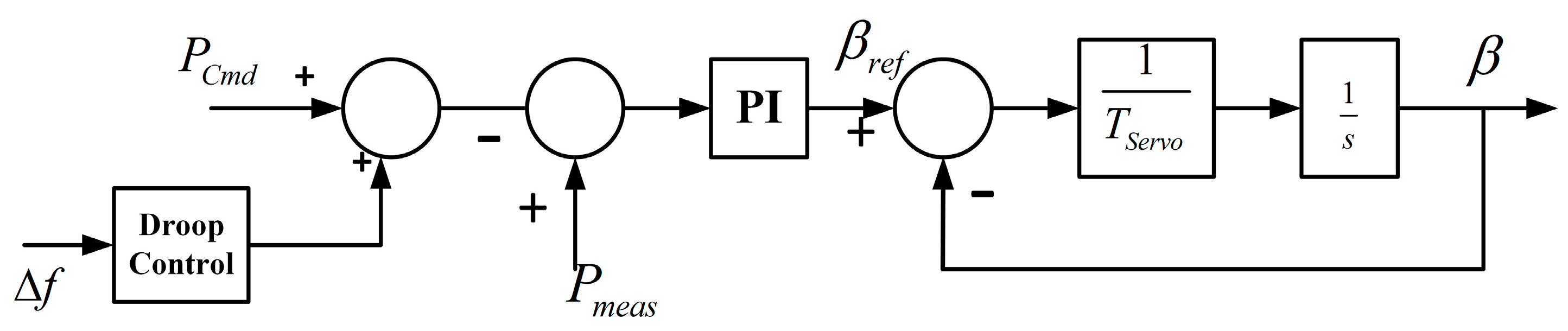
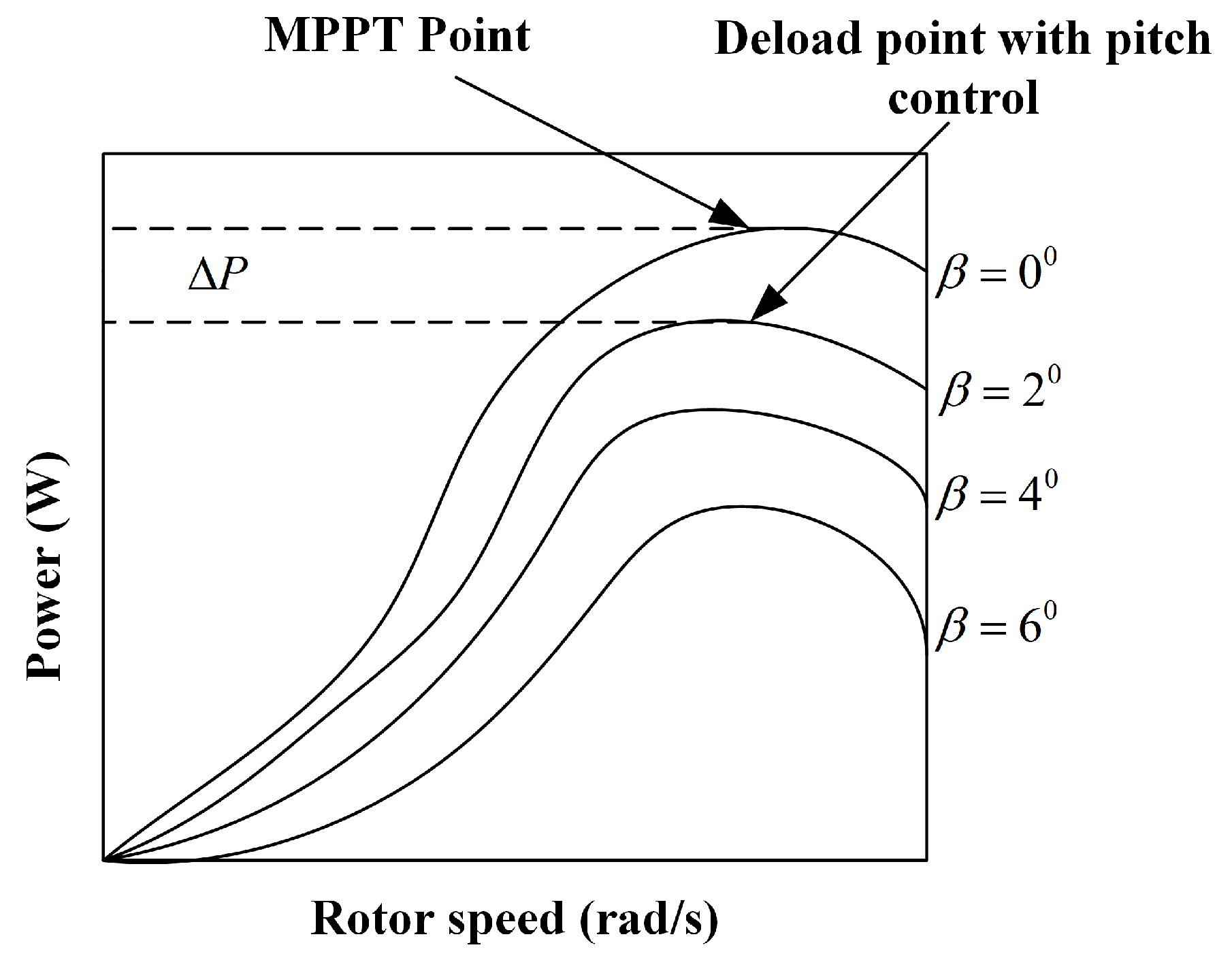
(b) Pitch Angle control
Another type of de-loading control for the wind turbines is created by changing the blade angle, known as “pitch angle control”. The pitch angle control can be applied to both variable speed and fixed speed wind turbines. Figure 15 illustrates the power-speed characteristics of a wind turbine for different pitch angles.
To de-load the wind turbine in pitch angle control, the pitch angle (beta) needs be increased to receive the active power reserve which is shown in Figure 16. Whenever the frequency event occurs, the pitch angle controller increases the value of beta and the operating point without changing the rotor speed. In pitch angle control, the pitch angle of the wind turbine is set at a sub-optimal point and reaches optimum value under frequency events to deliver/absorb active power. Pitch angle control is suited to high wind speed conditions [31].
Generally, the de-loading control can be selected depending upon the wind speeds. In low wind speeds, the de-loading is realized by the rotor speed control. The coordinated control of both pitch angle and rotor speed control is needed in medium wind speed conditions. The pitch angle control alone is used in high wind speed conditions.
3.1.5. Solar Photovoltaic Array in Frequency Regulation
The installed photovoltaic (PV) generators do not contribute to the active reserve power for frequency regulation. All the PV systems are operated at the maximum power point using MPPT algorithms and do not alter their active power output when load variation occurs. The PV systems also need to participate in the frequency regulation to maintain the power system stability, with an increasing penetration level of PV system in the power system. The frequency regulation is employed in two ways for the PV generators:
- De-loaded operation of PV.
- Use of ESS.
In solar photovoltaic arrays, both the inertial and primary frequency response can be implemented by using de-loaded operation of PV and ESS with proper control algorithms.
3.1.6. De-Loaded Operation of a PV Generator [32]
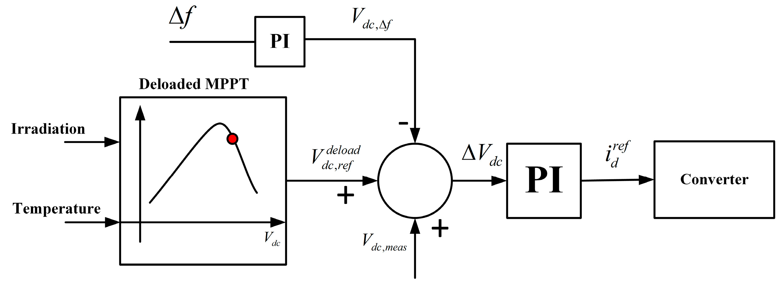
In the de-loaded operation of PV, the power electronic converters need to inject the required amount of power under imbalance conditions depending on the control signal generated in Figure 17.
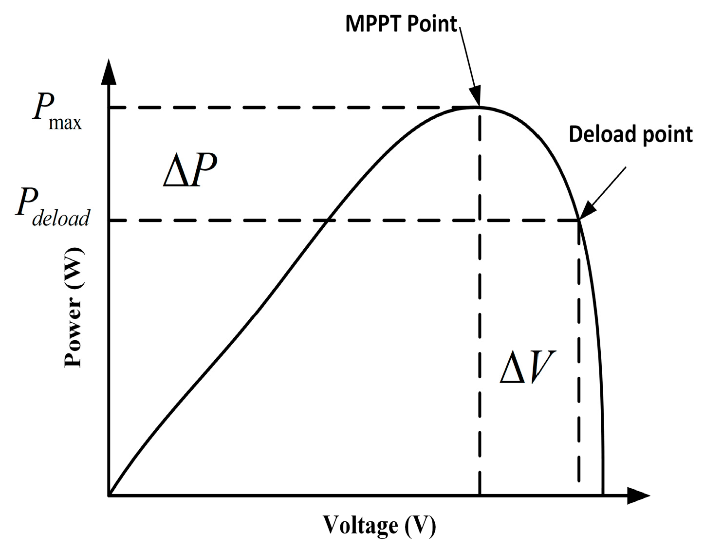
The solar power plants need to be operated under a sub-optimal power point below the maximum power point to maintain the active power reserve for the PV plants, as is shown in Figure 18. When the frequency event occurs, the operating voltage of the PV is decreased from the to , to increase the active power output. This reserve power will not be released until the frequency is deviated. When the frequency deviation occurs, the DC-link voltage is changed based on the frequency. The active power reserve available under de-loaded operation is known as,
The voltage reference calculated in the de-loaded operation is,
where, is the DC-link voltage.
3.2. Voltage Control Techniques
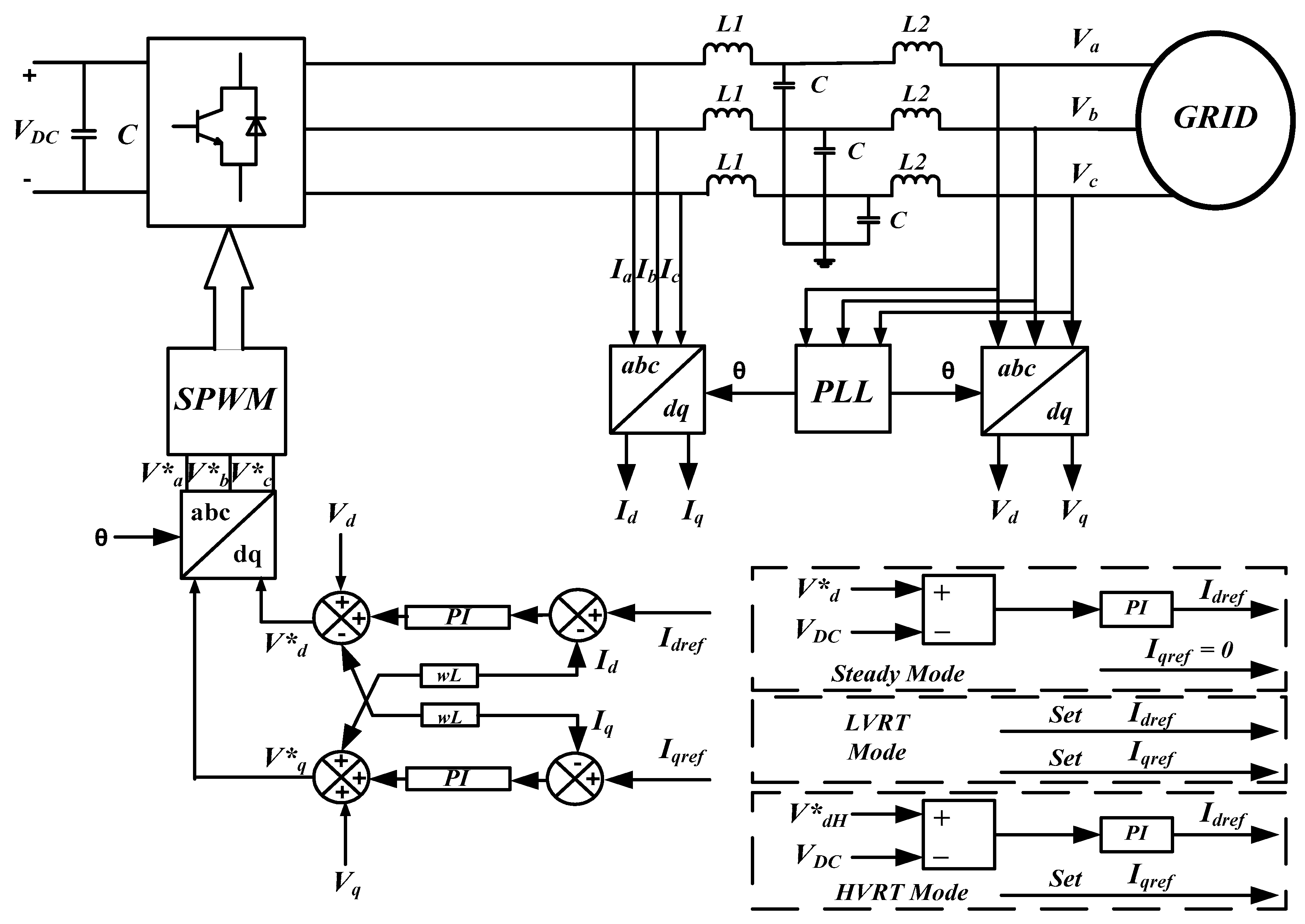
The control methods for voltage are discussed in two ways: (1) Low-voltage ride through (LVRT) and (2) High-voltage ride through (HVRT). The power disturbance in the grid is higher because of the output power from RES is irregular. Hence, LVRT should be attributed to the large capacity of grid-connected RES. The main purpose of LVRT is restricting the PCC current of the RES inverter, and power elements of RES inverter should not be damaged and tripped. The RES inverter is operated at 1.1 times the rated current in a short time, and it can supply a reactive current to support the grid voltage recovery. Thus, the control strategy of LVRT for RES is particularly dependent upon controlling the current output of the inverter during a grid fault [33]. Hence, to improve the power quality and stable operation of the grid, the RES is associated with the power system to serve the grid recovery from grid fault and to sustain the regulation of grid voltage and frequency.
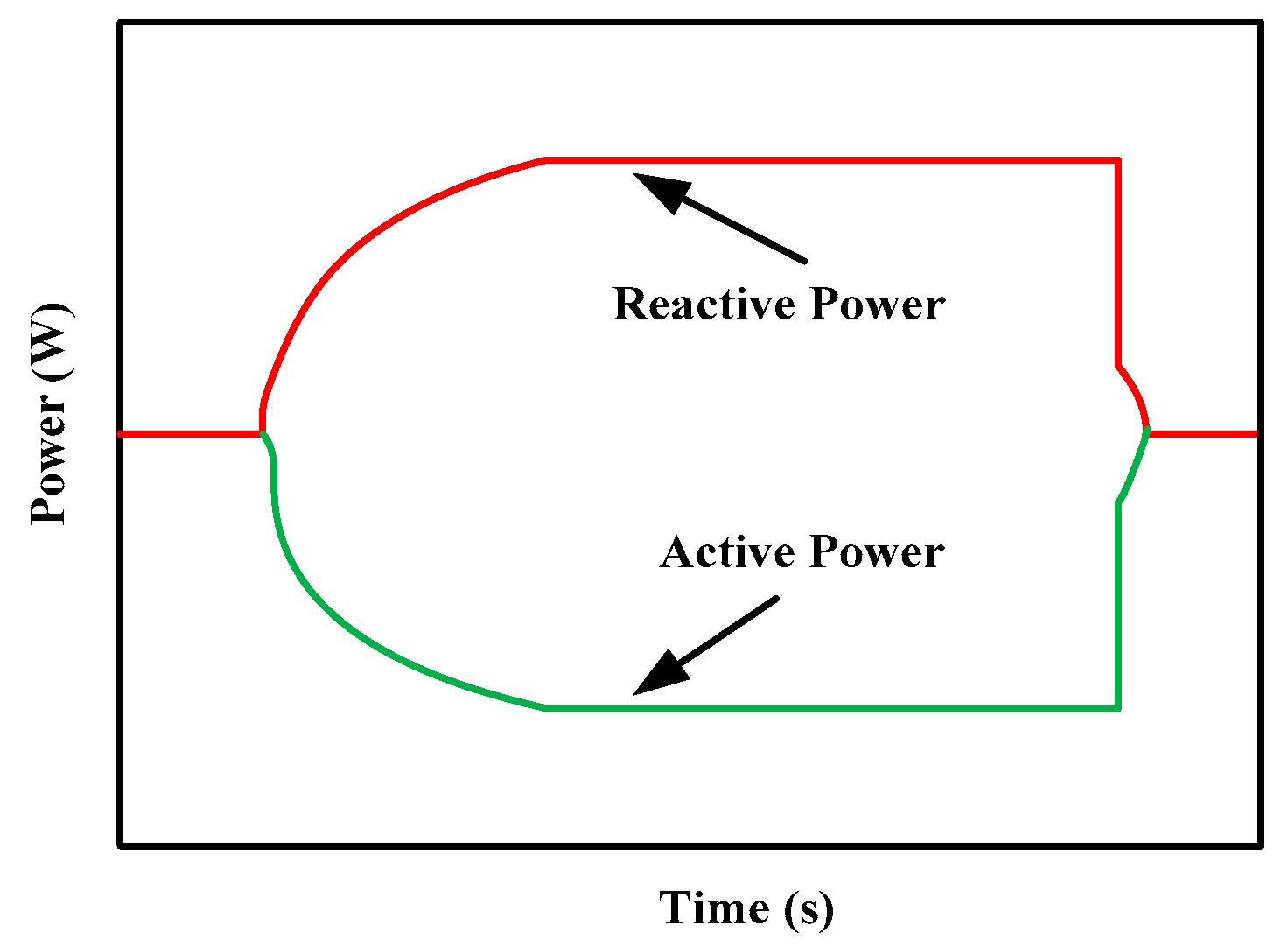
Developing the penetration of distributed generation (DG) systems into the grid, one of the major problems is sudden tripping of DG from the grid during faults occurring in the system such as power outages and voltage flickers. Hence, DG units need to support the grid during fault conditions. The reactive power support diagram is shown in Figure 19. According to the theory of instantaneous reactive power, the active and reactive currents are controlled by varying the amplitude and phase of the output voltage of the inverter. In daytime situations, the active power output and the reactive power compensation (RPC) of the system are obtained concurrently [34,35]. When the PV power is not available, the RPC characteristic of the RES can be employed to enhance the utilization factor of the system.
The main factors for RPC in a system are:
- (1)
- Regulating the voltage,
- (2)
- Improving the stability of the system,
- (3)
- Minimizing power losses,
- (4)
- Effective utilization of machines associated with the system.
During the LVRT, the RES has the ability to be associated with the grid when the voltage at PCC drops to a prescribed cut-out point. When the drop is below the prescribed point, the RES can switch from the grid. Hence, a certain amount of reactive power is needed to provide effective voltage support to overcome this fault situation [36].
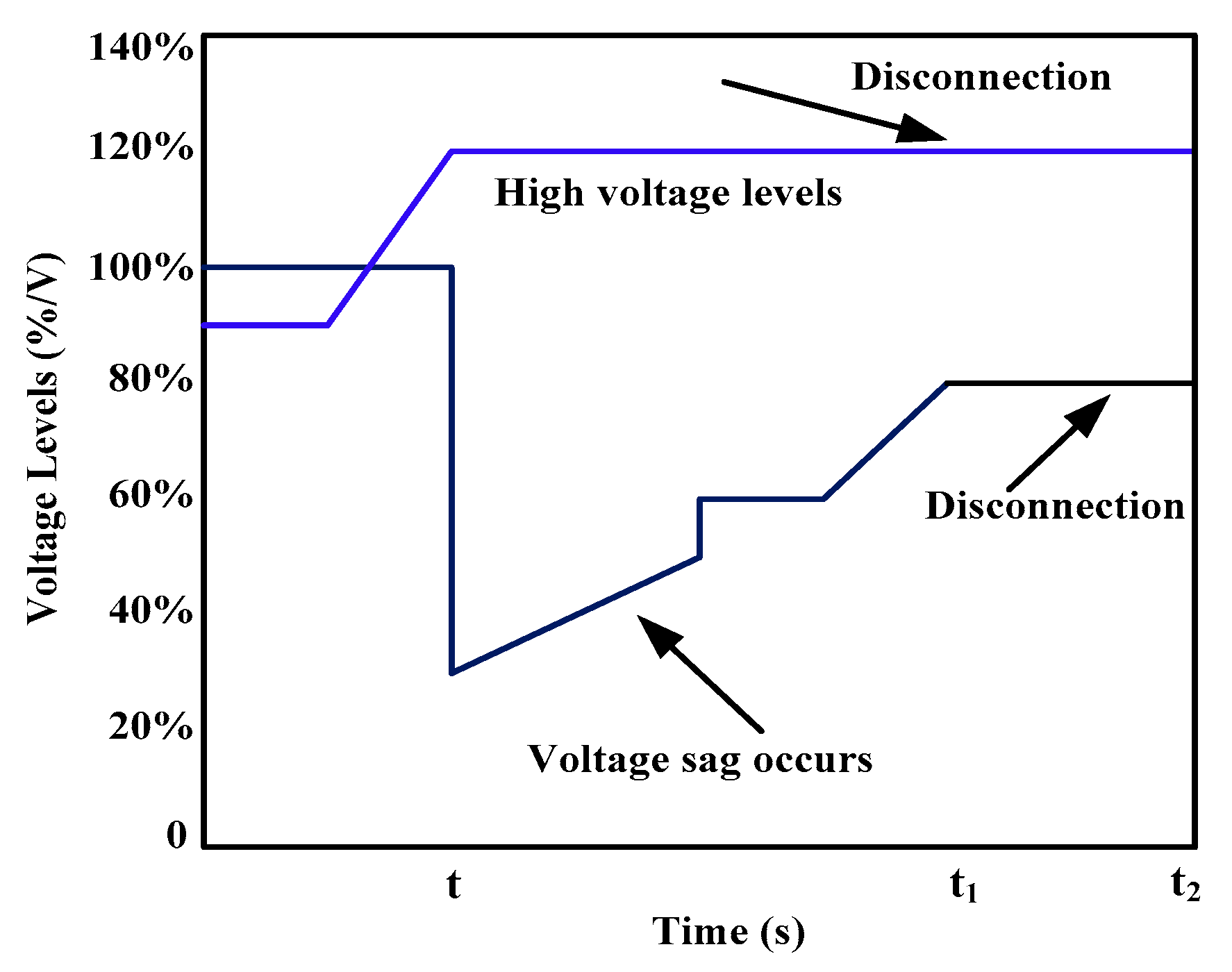
There are various causes for the PCC voltage to be above/below rated values, such as the load has been suddenly disconnected, earth faults, and the irrational control strategies. During HVRT conditions, The RES should consume a required reactive power in order to make the PCC voltage become lower. The amount of absorbing power is determined by the capacity of the inverter and voltage at the above level of the prescribed cut-off point. Hence, the active power supplied from RES should not be changed, so the RES inverter can utilize its capacity to consume reactive power [37].
The voltage requirements during the VRT at PCC are shown in Figure 20. The HVRT handles the grid faults, which depends on voltage rise. The HVRT functionality is used for each of the three voltage phases. Hence, the functionality is actuated when the voltage rises higher than the voltage level determined by the utility grid. The control requirements for LVRT and HVRT equations are presented in Equations (12)–(14).
The equation is to satisfy the demand requirement as follows,
where Imax is maximum reference current from RES system, and Id and Iq are the active and reactive currents. During a fault situation, the reactive support should meet the demand of Equation (12), and the active and reactive currents are set as follows,
where Id0 is the pre-fault current and IdrefH is the reactive reference current. The active power control activities are presented in Table 2.
4. ESS Support
The above section considers the various controllers for both solar and wind and discusses the maintenance of the power system stability without ESS. RES is intermittent in nature and may lead to stability issues if we completely rely on these sources for frequency stability. Hence, ESS needs to be used along with the RES to maintain the stability of power system under high penetration of RES. The frequency of the power system can be balanced by using an energy storage device. Whenever there is an imbalance between the demand and generation, the control algorithm acts at the ESS to deliver the required amount of the active power. The ESS support for RES issues diagram is shown in Figure 22.
The performance of ESS in the smart grid is an effort towards balancing generation, consumption, reduction of variations in RES, and also delivers high quality supply and reliability of the supply. There has been an evolution of the enhanced intelligent electricity network called “smart grid”, and it has a prominent contest of supporting all the sources connected with effective load control, powered from large penetration of non-dispatchable RES. These irregular energy sources are given higher levels of grid perception. Hence, ESS is the most significant smart grid advanced element to produce stable power at the grid level. ESS produces vital benefactions in defeating the complexity of irregular variation created by RES. It compensates the variation and lessens the variance among supply and demand [39]. ESS consists of pumped hydro-storage, compressed air energy storage (CAES), flywheel, superconducting magnetic energy storage (SMES), battery, and capacitors that are supposed to be widespread in RES integrated to the grid. ESS employs a power transformation system to integrate into the system network; they can add or receive both active and reactive power to balance for voltage changes in a short or medium duration. The ESS integration with the grid will increase the power quality, reliability, voltage support, backup power and decrease losses. When the irregular energy source reaches higher levels of grid penetration, ESS is the solution for providing a reliable energy supply [40,41]. Hence, proper coordination is needed for micro-grid (MG) and ESS operations. The main control methods among MG and ESS are the voltage, frequency, and active and reactive power controllers. Thus, ESS can sustain a balance within the generation and load at the instant of operation, and can also produce a firming potential of RES [42].
5. Smart Grid Features in Voltage Control with RES
Smart grid is being increasingly used in practice by electric utilities and involves the use of information, communication and control abilities to enhance the performance of the grid. The fundamental concept of a smart grid involves developing analysis, control, monitoring abilities of the traditional grid system, and reducing energy consumption. These objects are feasible over a system that can yield accurate and precise monitoring of the grid. A promising selection to minimize the challenges created by variations in RES is to add ESS into the grid. Another approach is to achieve flexible operation in energy consumption by employing demand side integration (DSI) or the usage of the micro-grid system. Moreover, the RES, ESS, and DSI are listed as one of the DERs. Hence, combining various aspects of certain sources is collectively essential in enhancing the utility of RES in the energy market [43].
6. Conclusions
The large-scale integration of RES into the power grid will have an impact on the stability of the power system. Both the frequency and voltage stability are highly affected by integrating large scale RES into the grid. This paper presented the issues related to high integration of RES in detail and reviewed their possible solutions available in the literature. To minimize frequency and voltage related issues, the several control techniques that are applied to wind and solar-based generators are summarized. Furthermore, ESS support could be used to maintain the stability and reduce the negative impacts related to grid integration as discussed.
Author Contributions
Initial idea purpose, data collection, formal analysis, original draft writing and editing: G.V.B.K. and R.K.S.; resources, supervision, review and editing: K.P., P.S., and J.B.H.-N.
Funding
No source of funding was attained for this research activity.
Acknowledgments
The authors would like to acknowledge the support and technical expertise received from the center for Bioenergy and Green Engineering, Department of Energy Technology, Aalborg University, Esbjerg, Denmark which made this publication possible.
Conflicts of Interest
The authors declare no conflict of interest.
References
- Ulbig, A.; Borsche, T.S.; Andersson, G. Impact of low rotational inertia on power system stability and operation. IFAC Proc. 2014, 19, 7290–7297. [Google Scholar] [CrossRef]
- Patel, M.R. Wind and Solar Power Systems: Design, Analysis, and Operation; CRC Press: Boca Raton, FL, USA, 2005; pp. 87–101. [Google Scholar]
- Zhong, Q.C. Virtual Synchronous Machines: A unified interface for grid integration. IEEE Power Electron. Mag. 2016, 3, 18–27. [Google Scholar] [CrossRef]
- Hales, D. Renewables 2018 Global Status Report, Renewable Energy Policy Network. 2018. Available online: http://www.ren21.net/status-of-renewables/global-status-report/ (accessed on 20 April 2019).
- Shah, R.; Mithulananthan, N.; Bansal, R.C.; Ramachandaramurthy, V.K. A review of key power system stability challenges for large-scale PV integration. Renew. Sustain. Energy Rev. 2015, 41, 1423–1436. [Google Scholar] [CrossRef]
- Eriksen, P.B.; Ackermann, T.; Smith, P.; Winter, W.; Garcia, J.M. System operation with high wind penetration. IEEE Power Energy Mag. 2005, 3, 65–74. [Google Scholar] [CrossRef]
- Huang, Z.M. Research of the problems of renewable energy orderly combined to the grid in smart grid. In Proceedings of the Asia-Pacific Power and Energy Engineering Conference (APPEEC), Chengdu, China, 28–31 March 2010. [Google Scholar]
- Lee, C.-T.; Hsu, C.-W.; Cheng, P.-T. A Low-Voltage Ride- Through Technique for Grid-Connected Converters of Distributed Energy Resources. IEEE Trans. Ind. Appl. 2011, 47, 1821–1832. [Google Scholar] [CrossRef]
- Zaman, B.A. 100\% Variable Renewable Energy Grid: Survey of Possibilities. Master’s Thesis, University of Michigan, Ann Arbor, MI, USA, 2018. [Google Scholar]
- Tamrakar, U.; Shrestha, D.; Maharjan, M.; Bhattarai, B.; Hansen, T.; Tonkoski, R. Virtual Inertia: Current Trends and Future Directions. Appl. Sci. 2017, 7, 654. [Google Scholar] [CrossRef]
- Cochran, J.; Denholm, P.; Speer, B.; Miller, M.; Cochran, J.; Denholm, P.; Speer, B.; Miller, M. Grid Integration and the Carrying Capacity of the US Grid to Incorporate Variable Renewable Energy; National Renewable Energy Laboratory: Golden, CO, USA, 2015. [Google Scholar]
- Carvalho, P.M.S.; Correia, P.F.; Ferreira, L. Distributed reactive power generation control for voltage rise mitigation in distribution networks. IEEE Trans. Power Syst. 2008, 23, 766–772. [Google Scholar] [CrossRef]
- El-Tamaly, H.H.; Wahab, M.A.A.; Kasem, A.H. Simulation of directly grid-connected wind turbines for voltage fluctuation evaluation. Int. J. Appl. Eng. Res. 2007, 2, 15–39. [Google Scholar]
- Katiraei, F.; Agüero, J.R. Solar PV integration challenges. IEEE Power Energy Mag. 2011, 9, 62–71. [Google Scholar] [CrossRef]
- Viawan, F.A.; Sannino, A.; Daalder, J. Voltage control with on-load tap changers in medium voltage feeders in presence of distributed generation. Electr. Power Syst. Res. 2007, 77, 1314–1322. [Google Scholar] [CrossRef]
- Knudsen, J.N.N.H. Introduction to the modelling of wind turbines. In Wind Power in Power Systems; Wiley: Chichester, UK, 2005. [Google Scholar]
- Sun, Y.; Member, S.; Zhang, Z.; Li, G.; Lin, J. Review on Frequency Control of Power Systems with Wind Power Penetration. In Proceedings of the International Conference on Power System Technology, Hangzhou, China, 24–28 October 2010; pp. 1–8. [Google Scholar] [CrossRef]
- Nguyen, H.T.; Yang, G.; Nielsen, A.H.; Jensen, P.H. Frequency Stability Enhancement for Low Inertia Systems using Synthetic Inertia of Wind Power. In Proceedings of the 2017 IEEE Power & Energy Society General Meeting, Chicago, IL, USA, 16–20 July 2017. [Google Scholar]
- Keung, P.; Li, P.; Banakar, H.; Ooi, B.T. Kinetic Energy of Wind-Turbine Generators for System Frequency Support. IEEE Trans. Power Syst. 2009, 24, 279–287. [Google Scholar] [CrossRef]
- El Itani, S.; Member, S.; Annakkage, U.D.; Member, S.; Joos, G. Short-Term Frequency Support Utilizing Inertial Response of DFIG Wind Turbines. In Proceedings of the 2011 IEEE Power and Energy Society General Meeting, San Diego, CA, USA, 24–29 July 2011; pp. 1–8. [Google Scholar] [CrossRef]
- Ye, H.; Pei, W.; Qi, Z. Analytical Modeling of Inertial and Droop Responses From a Wind Farm for Short-Term Frequency Regulation in Power Systems. IEEE Trans. Power Syst. 2016, 31, 3414–3423. [Google Scholar] [CrossRef]
- Wu, Y.; Yang, W.; Hu, Y.; Dzung, P.Q. Frequency Regulation at a Wind Farm Using Time-Varying Inertia and Droop Controls. IEEE Trans. Ind. Appl. 2019, 55, 213–224. [Google Scholar] [CrossRef]
- Ekanayake, J.; Holdsworth, L.; Jenkins, N. Control of DFIG wind turbines. Power Eng. 2003, 117, 28–32. [Google Scholar] [CrossRef]
- De Almeida, R.G.; Lopes, J.A.P. Participation of doubly fed induction wind generators in system frequency regulation. Power Syst. IEEE Trans. 2007, 22, 944–950. [Google Scholar] [CrossRef]
- El Mokadem, M.; Courtecuisse, V.; Saudemont, C.; Robyns, B.; Deuse, J. Experimental study of variable speed wind generator contribution to primary frequency control. Renew. Energy 2009, 34, 833–844. [Google Scholar] [CrossRef]
- Pradhan, C.; Bhende, C.N. Enhancement in Primary Frequency Regulation of Wind Generator using Fuzzy-based Control. Electr. Power Components Syst. 2016, 44, 1669–1682. [Google Scholar] [CrossRef]
- El Mokadem, M.; Courtecuisse, V.; Saudemont, C.; Robyns, B. Fuzzy Logic Supervisor-Based Primary Frequency Control Experiments of a Variable-Speed Wind Generator. IEEE Trans. Power Syst. 2009, 24, 407–417. [Google Scholar] [CrossRef]
- Zertek, A.; Member, S.; Verbi, G.; Member, S.; Pantoš, M. A Novel Strategy for Variable-Speed Wind Turbines’ Participation in Primary Frequency Control. IEEE Trans. Sustain. Energy 2012, 3, 791–799. [Google Scholar] [CrossRef]
- Vidyanandan, K.V.; Senroy, N. Primary Frequency Regulation by Deloaded Wind Turbines Using Variable Droop. IEEE Trans. Power Syst. 2013, 28, 837–846. [Google Scholar] [CrossRef]
- Ghosh, S.; Member, S.; Senroy, N. Electromechanical Dynamics of Controlled Variable-Speed Wind Turbines. IEEE Syst. J. 2015, 9, 639–646. [Google Scholar] [CrossRef]
- Moutis, P.; Member, G.S.; Loukarakis, E. Primary Load-Frequency Control from Pitch- Controlled Wind Turbines. In Proceedings of the 2009 IEEE Bucharest PowerTech, Bucharest, Romania, 28 June–2 July 2009; pp. 1–7. [Google Scholar] [CrossRef]
- Rahmann, C.; Castilo, A. Fast frequency response capability of photovoltaic power plants: The necessity of new grid requirements and definitions. Energies 2014, 7, 6306–6322. [Google Scholar] [CrossRef]
- Bae, Y.; Vu, Y.-K.; Kim, R.-Y. Implemental Control Strategy for Grid Stabilization of Grid-Connected PV System Based on German Grid Code in Symmetrical Low-to-Medium Voltage Network. IEEE Trans. Energy Convers. 2013, 28, 619–631. [Google Scholar] [CrossRef]
- Yu, H.; Pan, J.; Xiang, A. A multi-function grid-connected PV system with reactive power compensation for the grid. Solar Energy 2005, 79, 101–106. [Google Scholar] [CrossRef]
- El Moursi, M.S.; Xiao, W.; Kirtley, J.L. Fault ride through capability for grid interfacing large scale PV power plants. IET Gener. Transm. Distrib. 2013, 7, 1027–1036. [Google Scholar] [CrossRef]
- Firouzi, M.; Gharehpetian, G.B. LVRT Performance Enhancement of DFIG-Based Wind Farms by Capacitive Bridge-Type Fault Current Limiter. IEEE Trans. Sustain. Energy 2018, 9, 1118–1125. [Google Scholar] [CrossRef]
- Xie, Z.; Zhang, X.; Zhang, X.; Yang, S.; Wang, L. Improved Ride-Through Control of DFIG during Grid Voltage Swell. IEEE Trans. Ind. Electron. 2015, 62, 3584–3594. [Google Scholar] [CrossRef]
- Fan, S.; Chao, P.; Zhang, F. Modelling and simulation of the photovoltaic power station considering the LVRT and HVRT. J. Eng. 2017, 2017, 1206–1209. [Google Scholar] [CrossRef]
- Li, C.; Wang, R. Building integrated energy storage opportunities in China. Renew. Sustain. Energy Rev. 2012, 16, 6191–6211. [Google Scholar] [CrossRef]
- Basu, A.K.; Chowdhury, S.P.; Chowdhury, S.; Paul, S. Microgrids: Energy management by strategic deployment of DERs—A comprehensive survey. Renew. Sustain. Energy Rev. 2011, 15, 4348–4356. [Google Scholar] [CrossRef]
- Kumar, G.B.; Kumar, G.A.; Eswararao, S.; Gehlot, D. Modelling and control of bess for solar integration for pv ramp rate control. In Proceedings of the 2018 International Conference on Computation of Power, Energy, Information and Communication (ICCPEIC), Chennai, India, 28–29 March 2018; pp. 368–374. [Google Scholar]
- Michael, M.; Robert, S.; Percy, H.; Russ, N.; Robert, Y. Islands in the storm: Integrating microgrids into the larger grid. IEEE Power Energy Mag. 2013, 11, 33–39. [Google Scholar]
- Roscoe, A.J.; Ault, G. Supporting high penetrations of renewable generation via implementation of real-time electricity pricing and demand response. IET Renew. Power Gener. 2010, 4, 369–382. [Google Scholar] [CrossRef] [Green Version]
Figure 1.
Renewable energy share and targets by countries in 2017 and 2050 [4].
Figure 1.
Renewable energy share and targets by countries in 2017 and 2050 [4].

Figure 2.
RES integration with grid.

Figure 3.
Power balance in a power system network.

Figure 4.
Frequency response in a power system network.

Figure 5.
Grid connected system with RES and load.

Figure 6.
Frequency control techniques for RES.

Figure 7.
Hidden inertia emulation control [17].
Figure 7.
Hidden inertia emulation control [17].

Figure 8.
Inertia emulation control with droop control [18].
Figure 8.
Inertia emulation control with droop control [18].

Figure 9.
Fast power reserve characteristics.

Figure 10.
Fast power reserve control.

Figure 11.
Droop control for wind turbine.

Figure 12.
Droop characteristics.

Figure 13.
De-loaded operation for wind turbine.

Figure 14.
Speed control for wind turbine.

Figure 15.
Pitch angle controller.

Figure 16.
De-loaded curves with pitch angle control for wind turbine.

Figure 17.
De-loaded operation control for solar photovoltaic (PV).

Figure 18.
Frequency response in power system network.

Figure 19.
Reactive power support diagram.

Figure 20.
Voltage requisites during the low-voltage ride through (LVRT) and high-voltage ride through HVRT at PCC [38].
Figure 20.
Voltage requisites during the low-voltage ride through (LVRT) and high-voltage ride through HVRT at PCC [38].

Figure 21.
Control diagram of the LVRT and HVRT [38].
Figure 21.
Control diagram of the LVRT and HVRT [38].

Figure 22.
Energy Storage System (ESS) support for RES issues.


Table 1.
The comparison of renewable energy sources (RES) with synchronous generator (SG) [5].
Table 1.
The comparison of renewable energy sources (RES) with synchronous generator (SG) [5].
| Characteristics | Solar | Wind | SG |
|---|---|---|---|
| Fluctuations | More | Less | No |
| Cost for large scale | More | Medium | Low to medium |
| Maintenance cost | Minimum | More | Moderate |
| Inertia | No inertia | Low inertia | High |
| Capacity factor | Very Low | Low to medium | More |
| Annual growth in power industry | Very High | More | More |
Table 2.
Active power control activities [38].
Table 2.
Active power control activities [38].
| Time | Working State | Principle |
|---|---|---|
| (0, t) | steady state | Basic control principle |
| (t, t1) | steady state to fault state | Id is from (12) |
| (t1, t2) | recovery state | recovery rate set between t1 to t2 |
| (t2, ~) | steady state | Basic control principle |
© 2019 by the authors. Licensee MDPI, Basel, Switzerland. This article is an open access article distributed under the terms and conditions of the Creative Commons Attribution (CC BY) license (http://creativecommons.org/licenses/by/4.0/).
Share and Cite
MDPI and ACS Style
Kumar, G.V.B.; Sarojini, R.K.; Palanisamy, K.; Padmanaban, S.; Holm-Nielsen, J.B. Large Scale Renewable Energy Integration: Issues and Solutions. Energies 2019, 12, 1996. https://doi.org/10.3390/en12101996
AMA Style
Kumar GVB, Sarojini RK, Palanisamy K, Padmanaban S, Holm-Nielsen JB. Large Scale Renewable Energy Integration: Issues and Solutions. Energies. 2019; 12(10):1996. https://doi.org/10.3390/en12101996
Chicago/Turabian StyleKumar, G. V. Brahmendra, Ratnam Kamala Sarojini, K. Palanisamy, Sanjeevikumar Padmanaban, and Jens Bo Holm-Nielsen. 2019. "Large Scale Renewable Energy Integration: Issues and Solutions" Energies 12, no. 10: 1996. https://doi.org/10.3390/en12101996
Note that from the first issue of 2016, this journal uses article numbers instead of page numbers. See further details here.