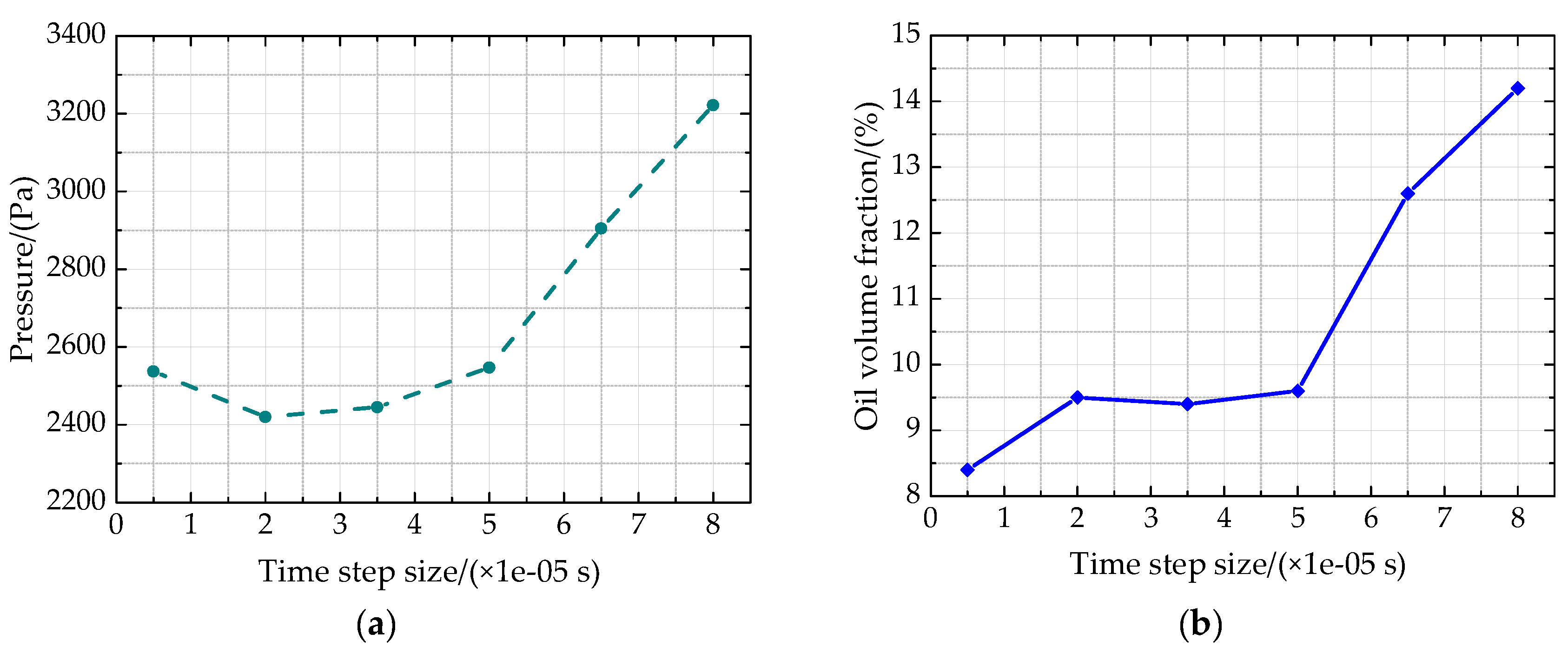
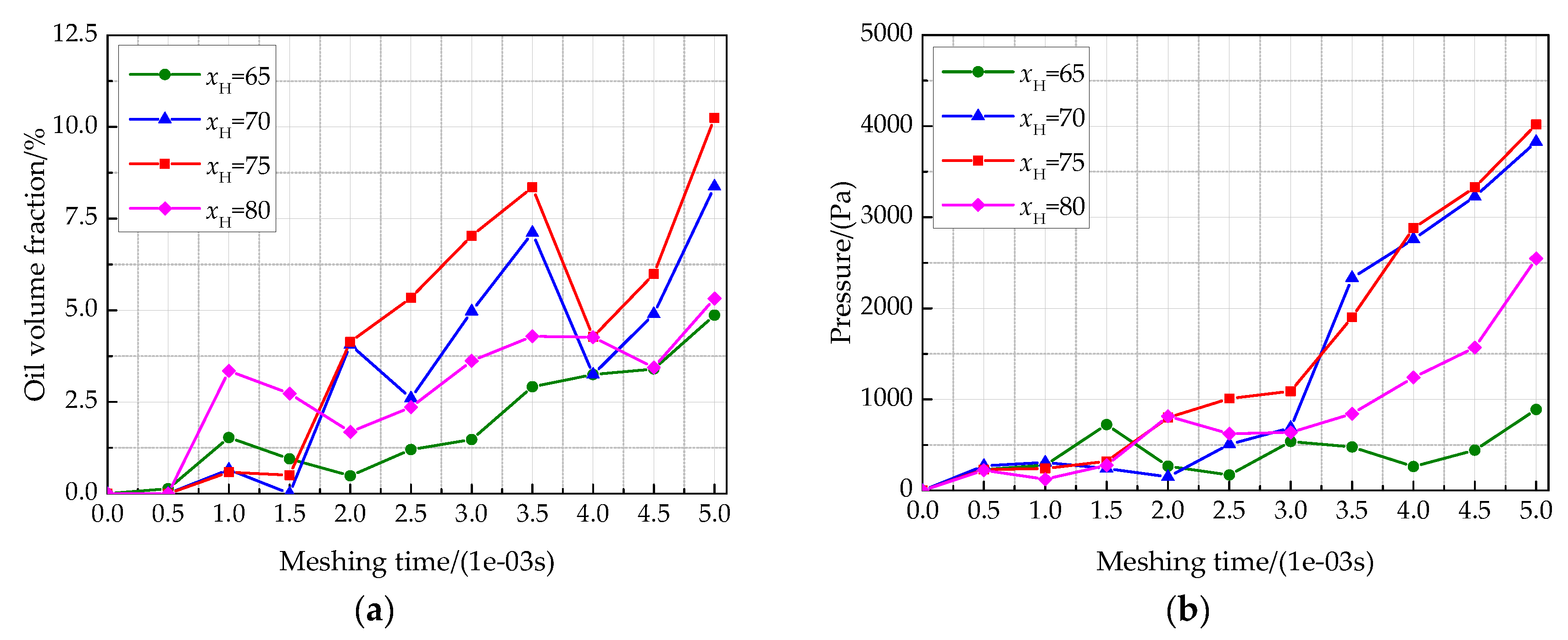
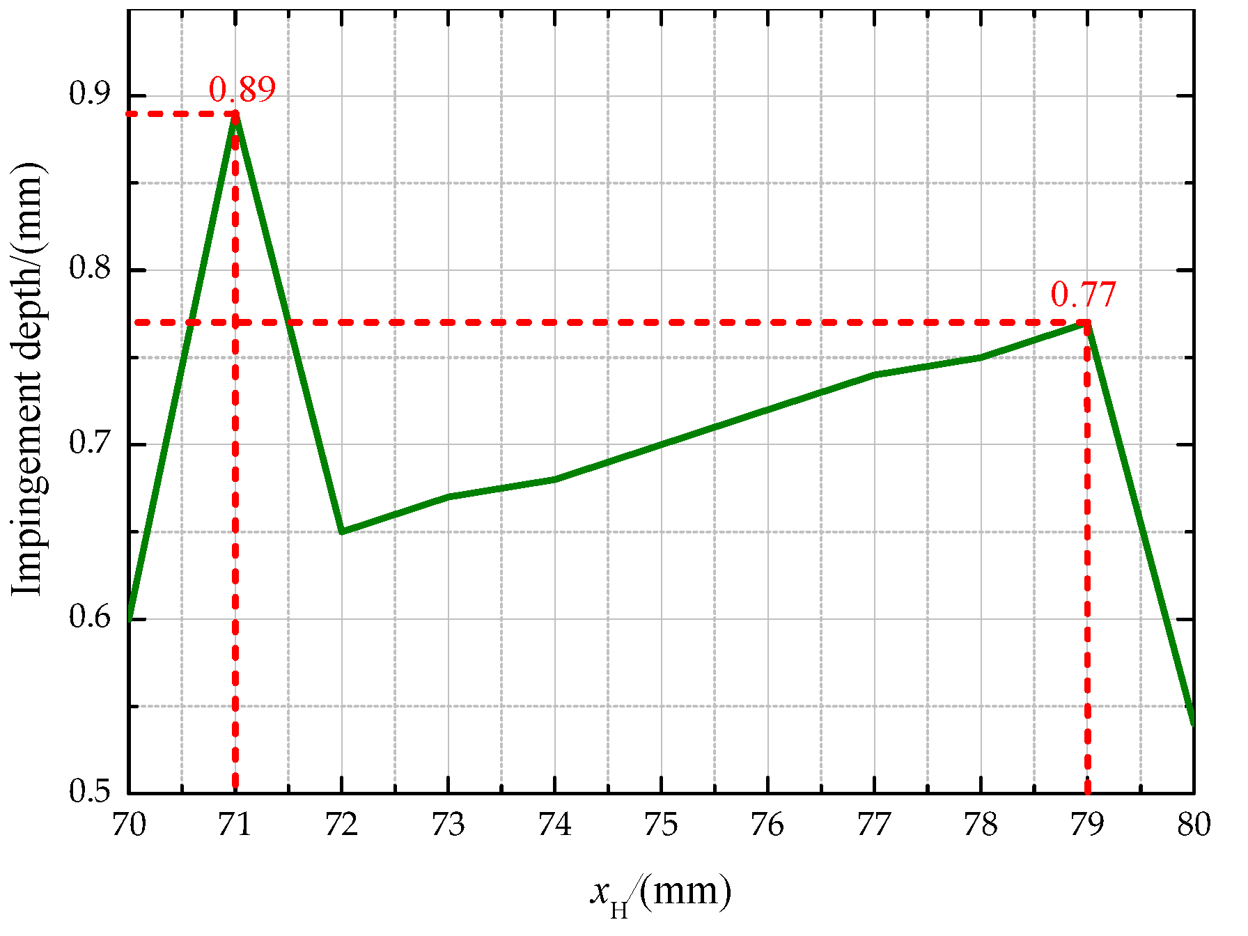
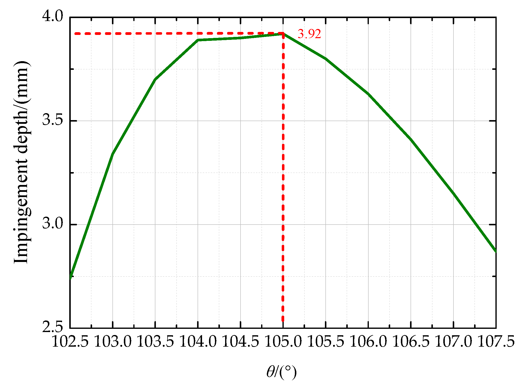
The derivation steps for the mathematical model of the impingement depth are as follows:
2.1. Definitions of Nozzle Layout Parameters
For the orthogonal face gear drive, the tooth contact type is point contact, and the meshing process can be regarded as the involute spur gear meshing with the rack at different shaft cross sections [
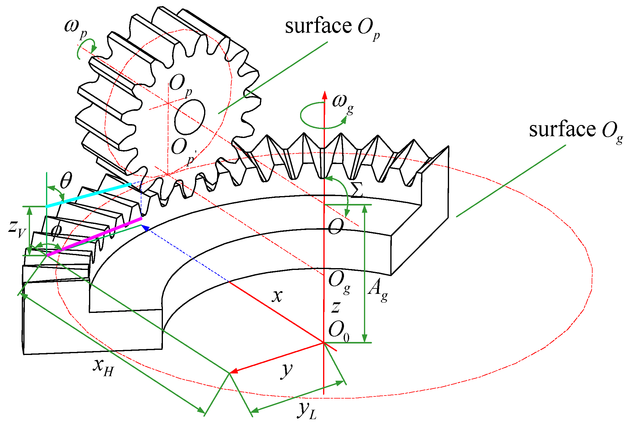
25]. The space coordinate system is set up as shown in
Figure 2. At this time, there is a circle on the pinion pitch cylinder rolling purely with a circle along the direction of the face gear radius. Point
is the gear coordinate origin, representing the center of the gear-locating surface. The x-axis represents the intersection line between the symmetry surface and the locating surface of the face gear. The z-axis represents the axis of the face gear. The y-axis can be determined by the right-hand rule. Point
represents the intersection point of the face gear axis and the pinion axis. Furthermore, points
and
represent the centers of the surfaces through impingement points and perpendicular to the pinion axis and the face gear axis, respectively.
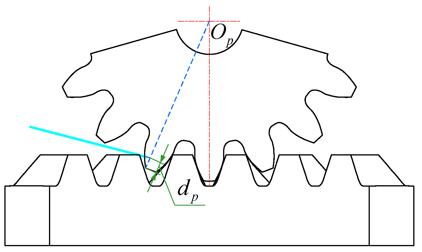
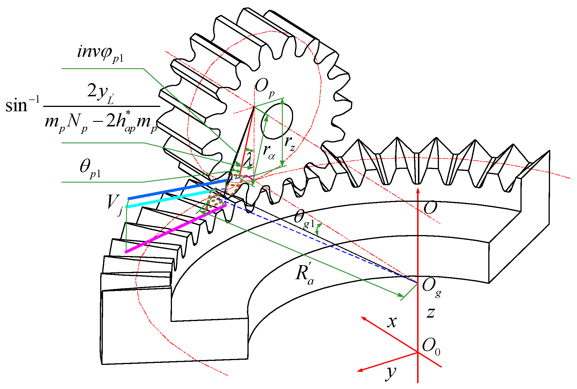
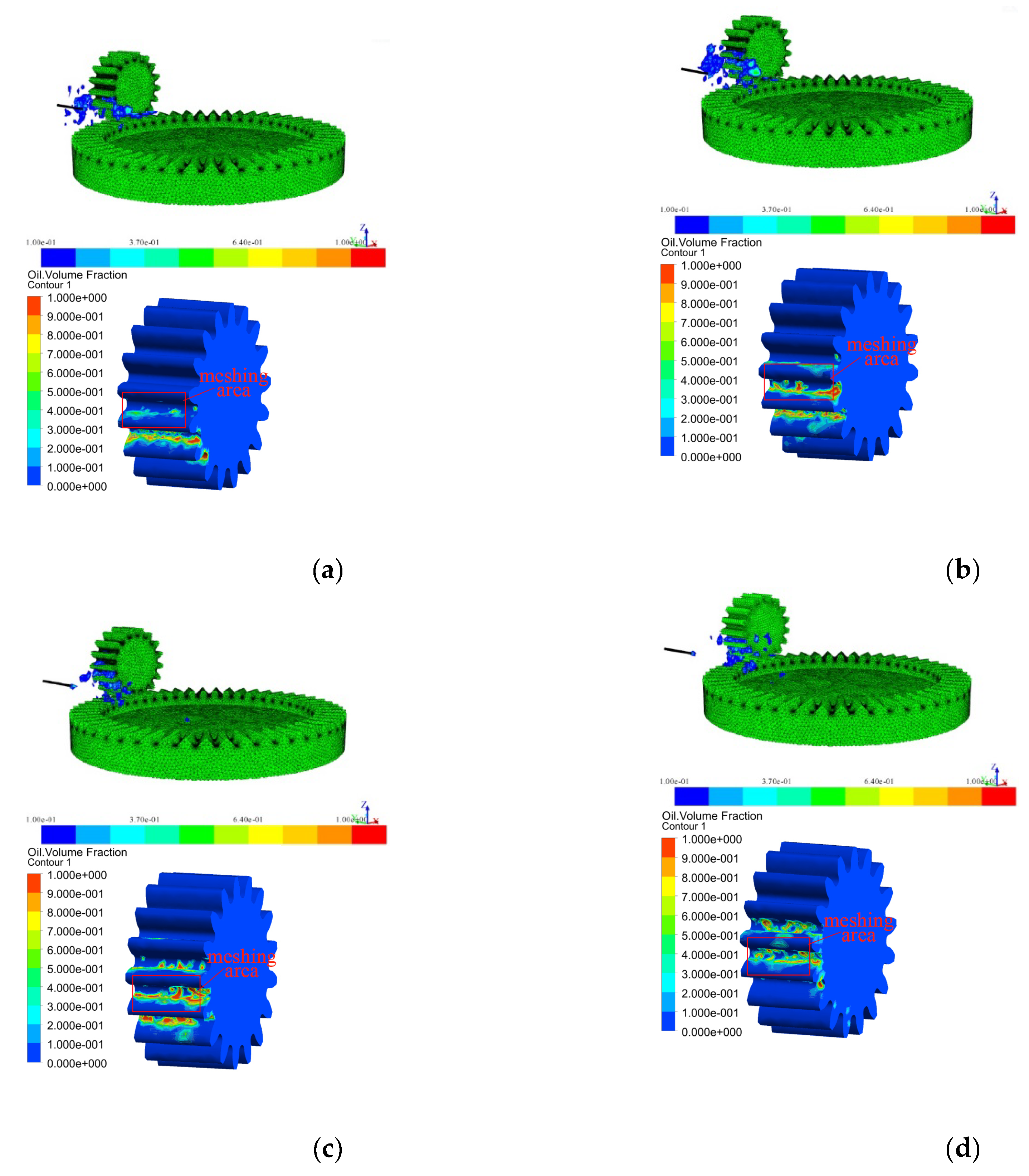
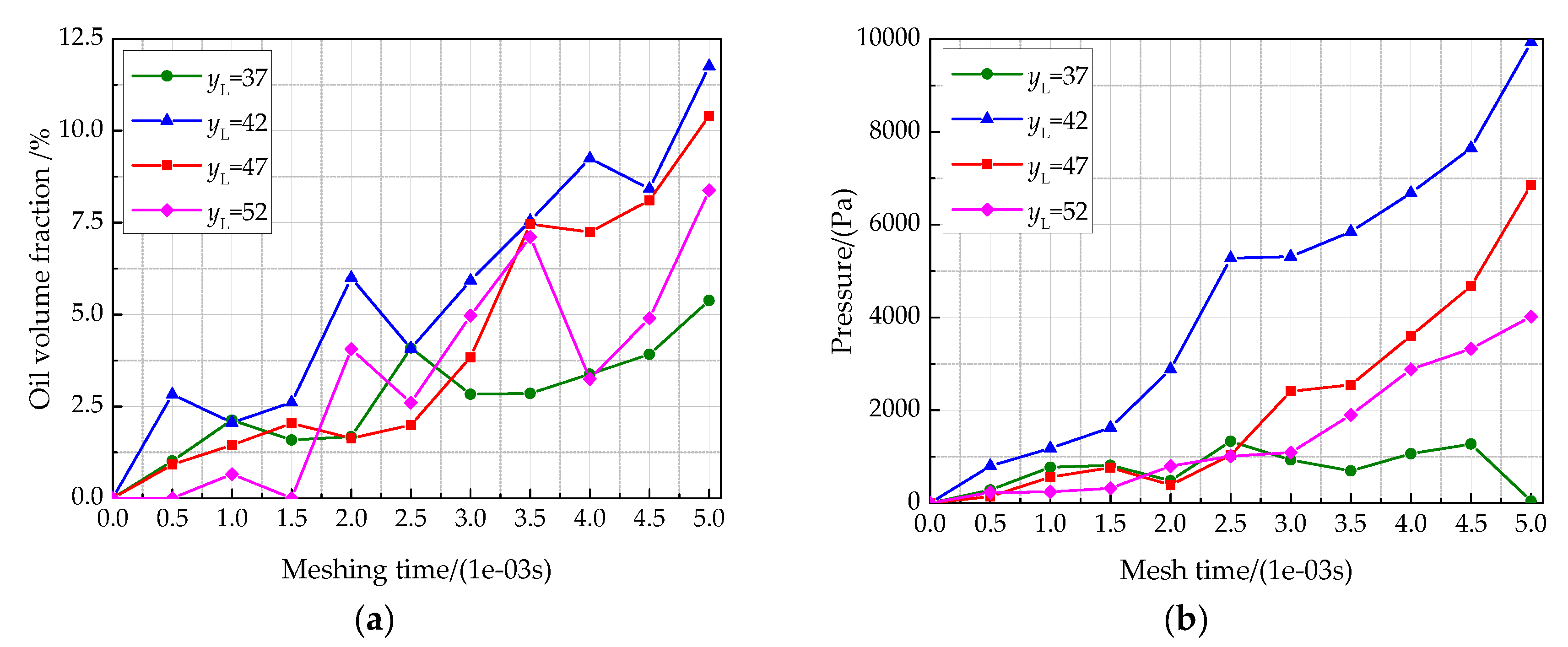
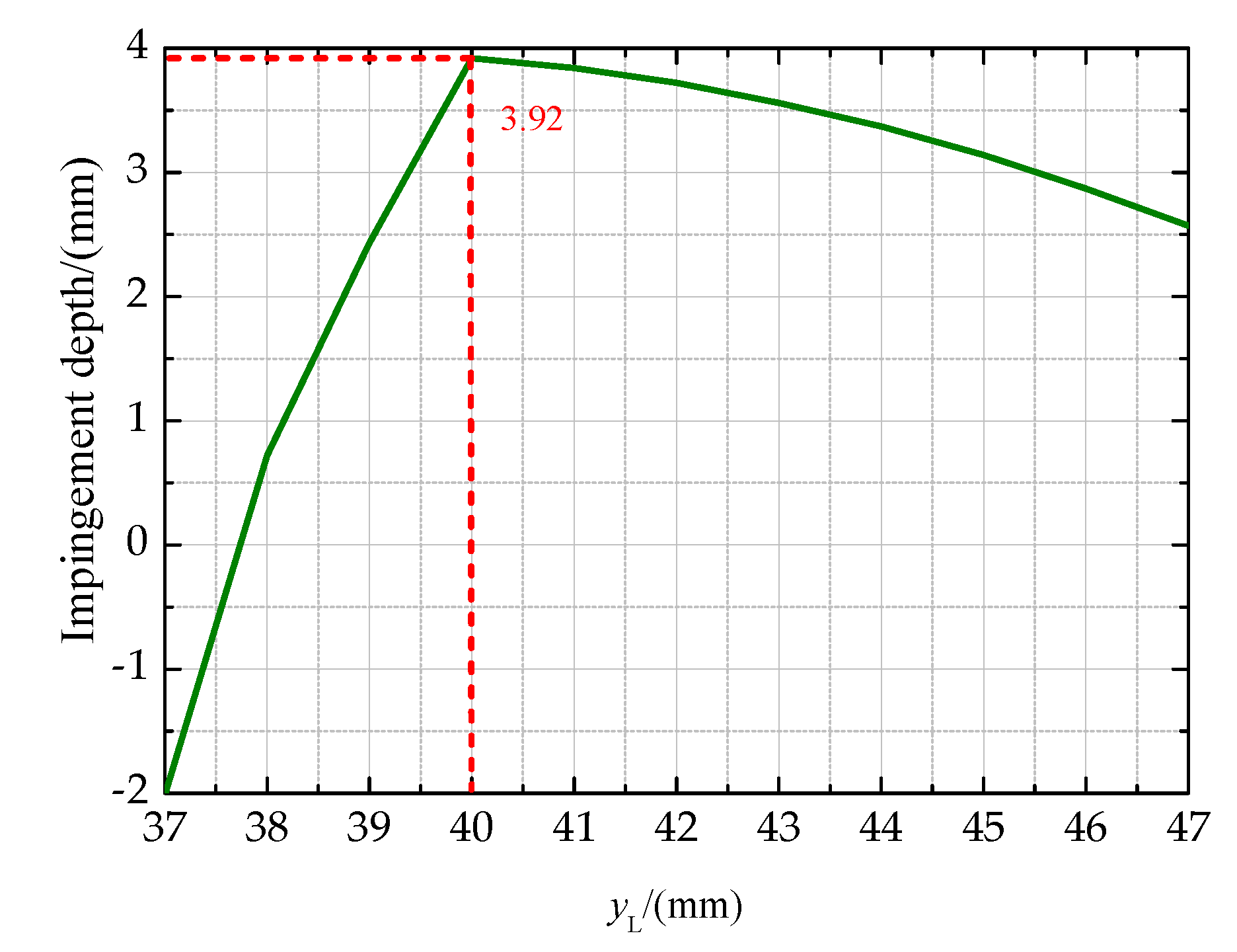
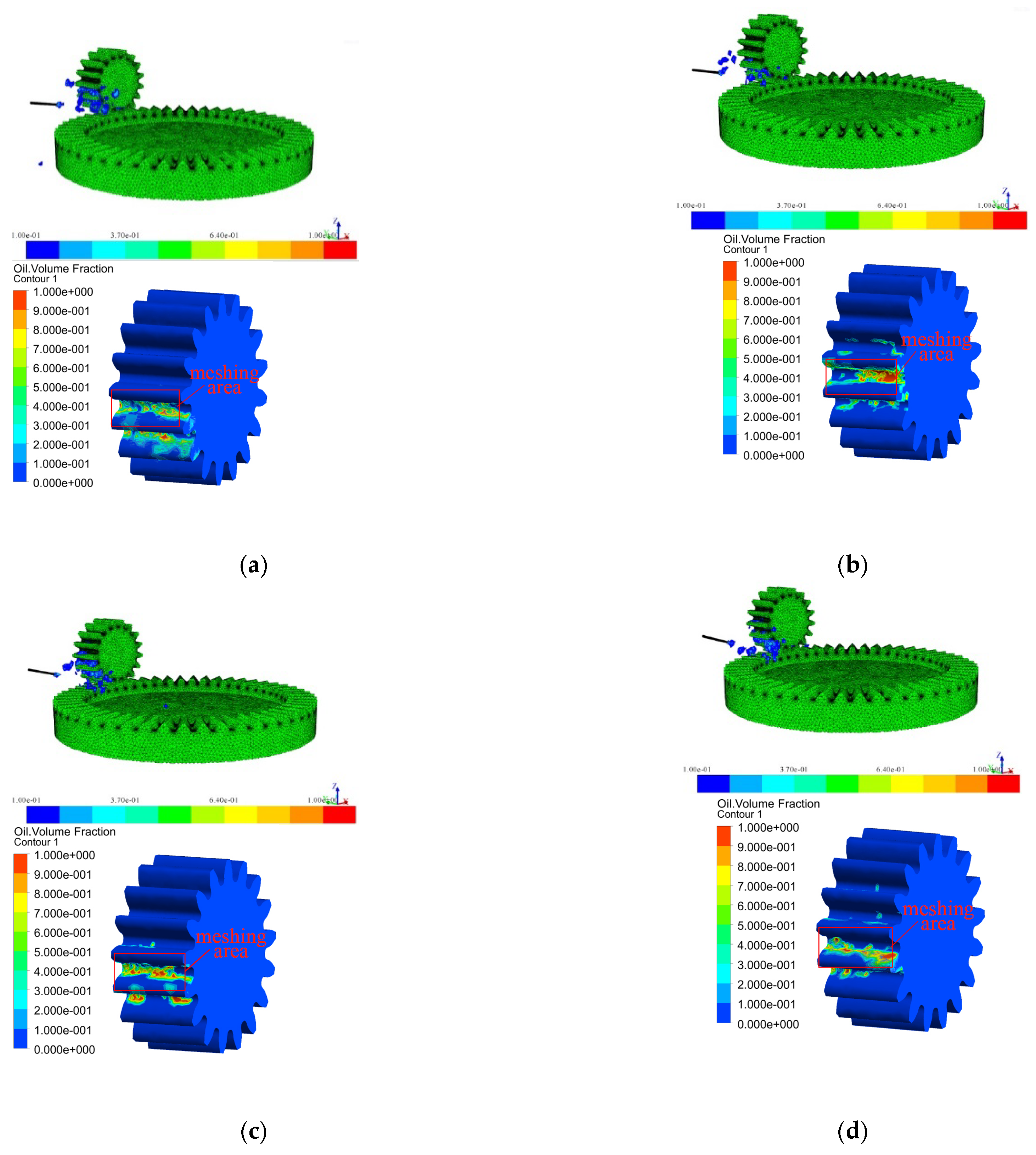
As shown, the impingement depth is directly relevant to the jet orientation parameters and . denote the nozzle exit position; the parameter denotes the angle between the jet stream and the z-axis, which is always restricted to , and the parameter denotes the angle between the jet stream projection line on the plane and the x-axis. Since the pinion is an involute spur gear with a symmetrical structure, this paper focuses on the case that the jet stream is parallel to the pinion shaft cross section, that is . Additionally, denotes the shaft angle of the face gear pair, and is the distance from the pinion axis to the plane.
2.2. Mathematical Model for the Pinion
The oil jet orientation parameters are known initially, and the distance and the oil jet velocity are also given. Thus, the process for calculating the impingement depth of the pinion is as follows.
At the initial moment (
t0 = 0): the position parameters of the face gear pair and the jet stream are as illustrated in
Figure 3.
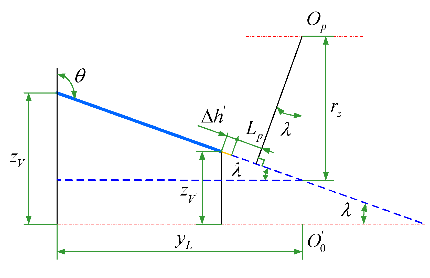
According to
Figure 3, the projection length of the line from the point
to the face gear addendum on the surface
can be expressed as
Substituting the parameter
, Equation (1) can be written as
where
denotes the z coordinate value of the point where the jet stream passes through the face gear addendum. Let
be the distance from the face gear addendum to the
plane; thus,
It is known that the jet streamline is parallel to the pinion shaft cross-section; that is, the jet stream is perpendicular to the x-axis. According to
Figure 3, the projections of the jet stream on the surface
and surface
are demonstrated in
Figure 4a,b. Furthermore, in
Figure 4b, the perpendicular line of the projection line is drawn through the point
, and the length of the perpendicular line is
.
According to the geometric relationship in
Figure 4a, the following equation is obtained:
Equations (2), (3) and (4) can be rewritten in a combined form:
where
and
represent the x and y coordinate values of the point where the jet stream passes through the face gear addendum, respectively.
The following equations can be obtained from
Figure 4b:
By solving Equations (6), (7), (8) and (9),
and
can be expressed as
where
denotes the distance from the intersection point of the jet stream with line
to the point
;
denotes the angle between the line
and the line
.
and
represent the position parameters of the pinion and the face gear at the initial time (
), and their relationship can be deduced by the rotation angle relationship between the face gear and the gear shaper cutter during the machining process. The rotation angles
and
of the face gear and the gear shaper cutter satisfy the transmission ratio [
26]:
where
and
denote the numbers of teeth on the shaper and the face gear, respectively.
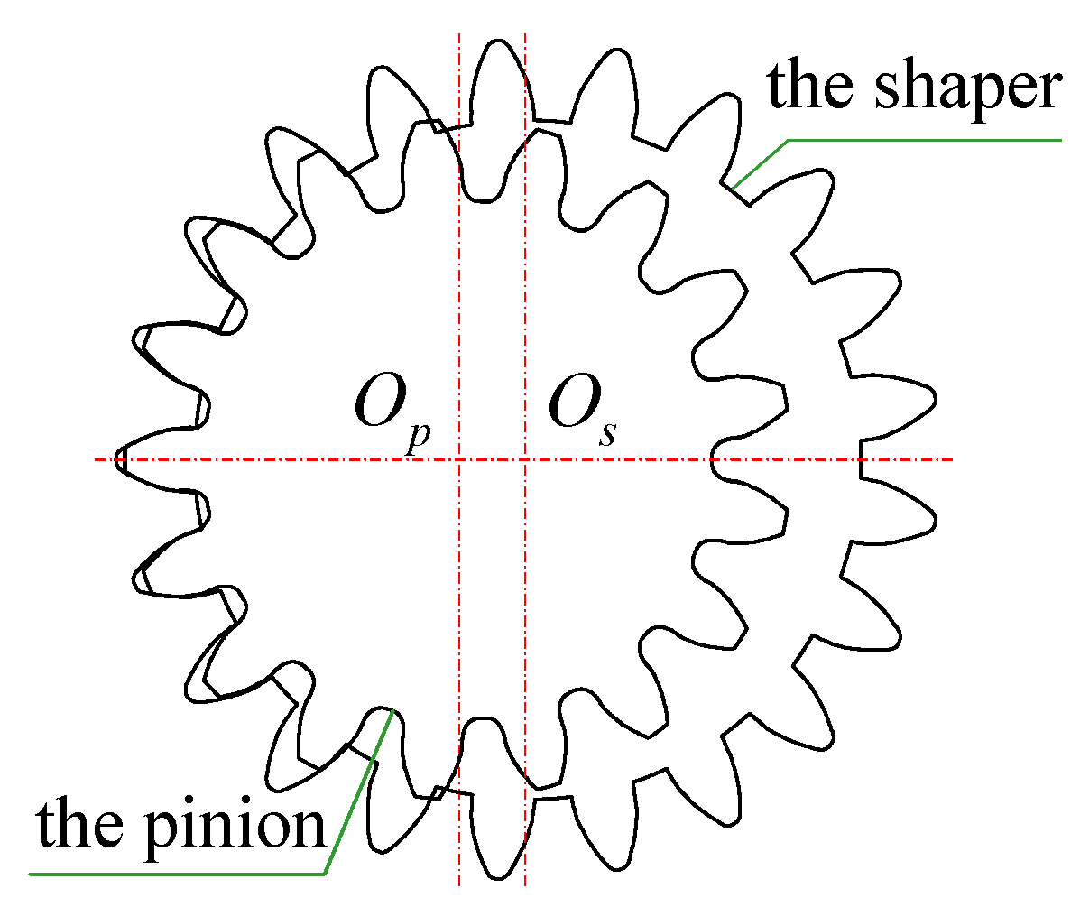
To avoid the interference between the shaper cutter and the edge of the face gear, the face gear drive is changed from an instantaneous line contact to a point contact drive. In this case, the number of teeth on the pinion will be 1–3 teeth less than on the gear shaper cutter [
27,
28,
29].
Figure 5 illustrates an imaginary internal tangency of the shaper cutter and the pinion [
30,
31].
and
denote the centers of the pinion and the shaper cutter shaft sections, respectively. Their rotation angles satisfy the following equation:
Combining Equation (12) with Equation (14), the relationship between the rotation angle
of the pinion and
of the face gear can be expressed as:
According to
Figure 3 and Equation (15), the initial position parameter
of the pinion is expressed by
where
is the involute function of the spur gear, representing the spread angle at the intersection point between the pinion pitch circle and the involute; and the pressure angle
on pitch circle of the pinion is expressed as
Obviously, from
Figure 4, the initial position parameter
of the face gear is
At the moment (
), the position parameters of the face gear pair and the jet stream are illustrated in
Figure 6.
As the flowing time of the jet steam is equal to the rotation time of the pinion, which is rotating from the angle
at the initial time
to the angle
at time
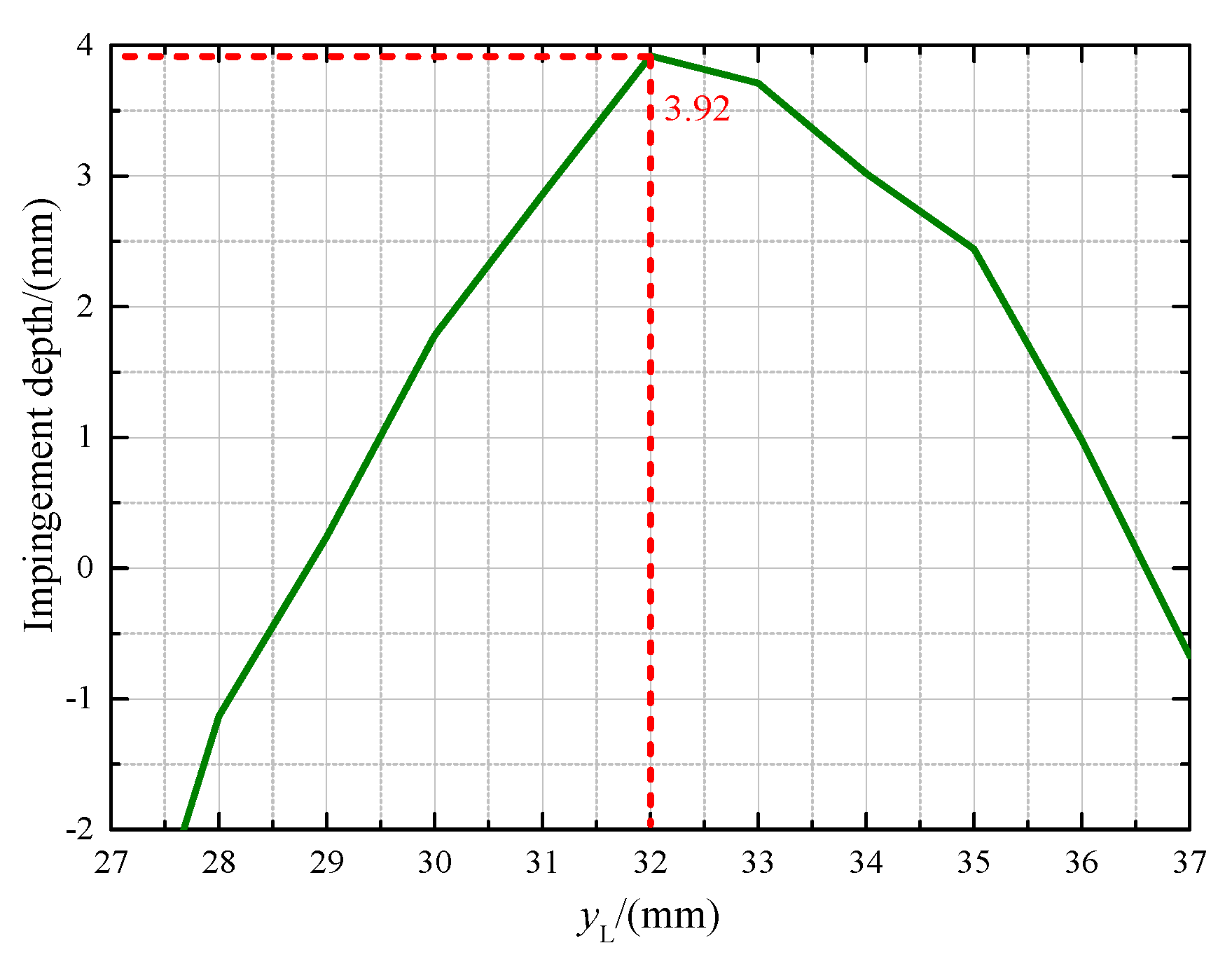
, the impingement depth
can be calculated as
where
where
represents the impingement distance, and
represents the addendum radius of the pinion.
where
is the angular velocity of the pinion.
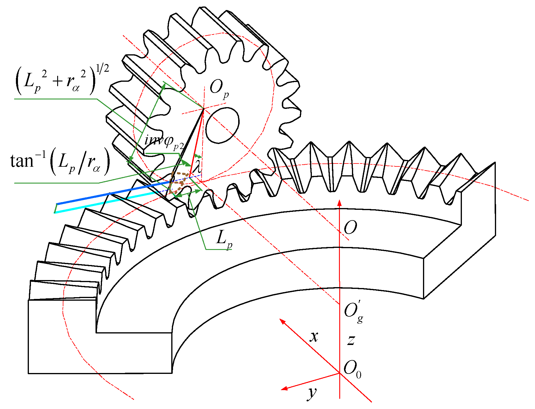
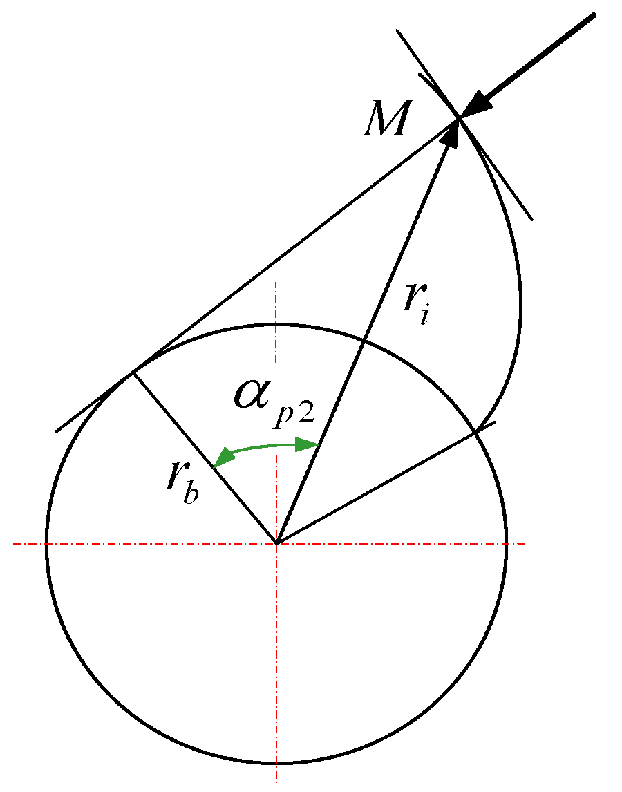
As can be seen in
Figure 6, the position parameter of the pinion at
is
where
is the involute function of the spur gear, denoting the spread angle at the impingement point M of the involute shown in
Figure 7;
denotes the pressure angle at the impingement point on the volute. Their relationship can be obtained by
The following equations can be obtained from
Figure 6 and
Figure 7:
where
denotes the radius of the pinion at the impingement point, and
denotes the base circle radius of the pinion.
Equation (21) can be rewritten as
Figure 8 illustrates the projection of the jet stream on the surface
; according to the geometric relationship, the following equation can be obtained:
This can be simplified by substituting Equation (7) into Equation (27):
where
denotes to the projection of
on the surface
. Hence, the relationship between
and
is
Moreover, Equation (19) can be reformulated as
By substituting Equations (3), (10), (11), (20) and (26) into Equations (28) and (29), the mathematical model of the impingement depth on the pinion can be established as follows:
where
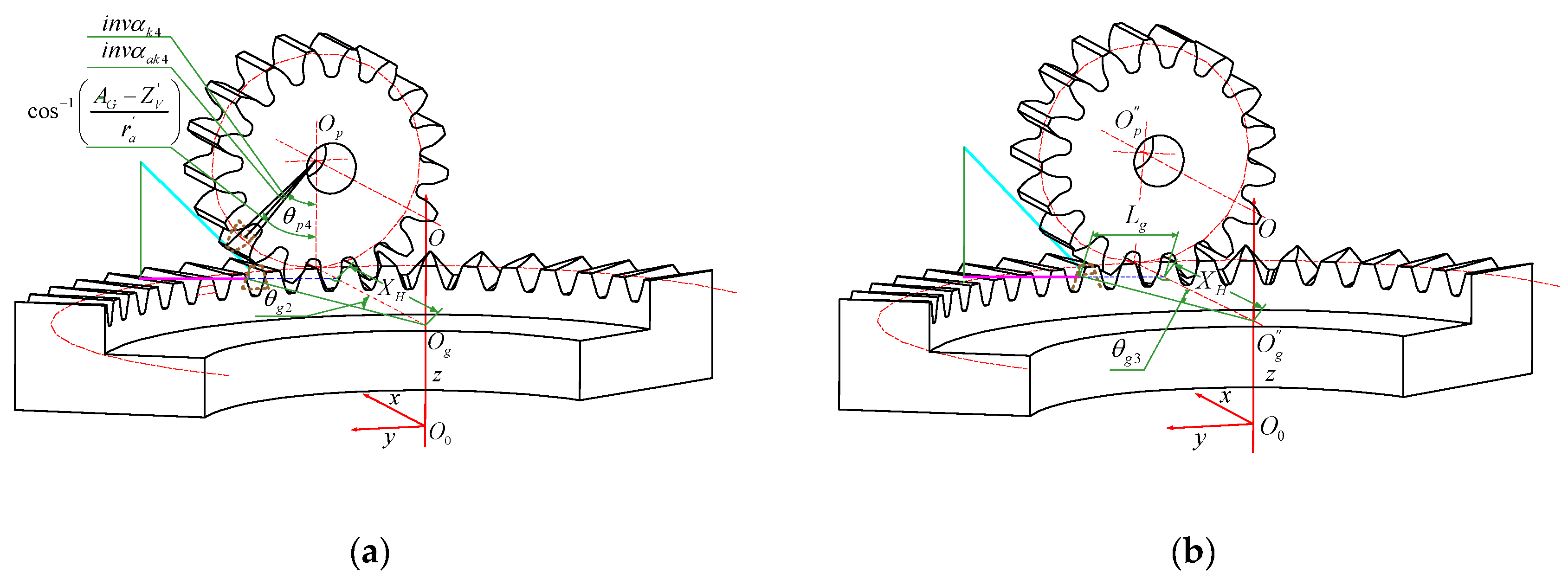
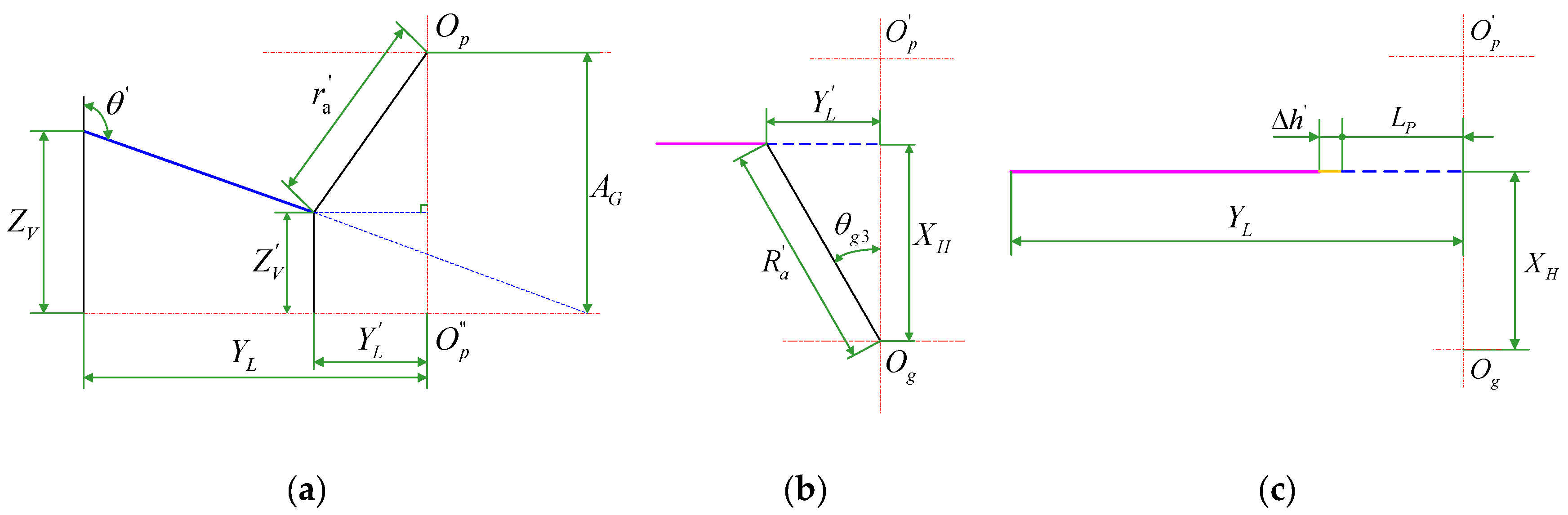
2.3. Mathematical Model for the Face Gear
The deduction process of the mathematical model of impingement depth for the face gear is approximately the same as that for the pinion; therefore, only the main derivation steps are presented in this paper. The position parameters of the face gear pair and the jet stream at the initial moment (
) and the moment (
) are as illustrated in
Figure 9a,b, respectively.
Additionally, projections of the jet stream on different surfaces at different moments are shown in
Figure 10.
Similarly, the position parameters of the pinion and the face gear at the initial time (
) and the face gear at the moment (
) are denoted by
,
and
, respectively, which can be calculated using the following expressions
where
denotes the distance from the pinion axis to the
plane;
denotes the z coordinate value of the point where the jet stream passes through the pinion addendum;
and
denote the pressure angles at the intersection point of the addendum circle and the pitch circle with the involute, respectively;
denotes the impingement distance; and
are the jet orientation parameters.
According to the definition of the impingement depth, there is an angle between the line from the impingement point to the face gear addendum and the z-axis. The impingement depth on the face gear is assumed to be equal to its projection on the surface
. Hence, similar to Equation (19), the impingement depth
on the face gear can be calculated as
where
is the inner radius of the face gear,
is the impingement distance, which satisfies the expression
, while
is defined as
, which is the projection of
on the surface
, as shown in
Figure 10a,c.
Therefore, the mathematical model of the impingement depth
on the face gear can be established as
where
where
denotes the jet velocity;
denotes the angular velocity of the face gear.


