Review, Comparison, and Proposal for PWM Converters Integrating Differential Power Processing Converter for Small Exploration Rovers


1
College of Engineering, Ibaraki University, Hitachi 316-8511, Japan
2
Toyota Motor Corporation, Toyota City 471-8571, Japan
3
Japan Aerospace Exploration Agency, Tsukuba 305-8505, Japan
*
Author to whom correspondence should be addressed.
Energies 2019, 12(10), 1919; https://doi.org/10.3390/en12101919
Submission received: 14 April 2019
/
Revised: 9 May 2019
/
Accepted: 16 May 2019
/
Published: 20 May 2019
(This article belongs to the Special Issue PV Systems: from Small- to Large-Scale)
Abstract
:Partial shading often appears on photovoltaic (PV) strings installed in small space probes, such as moon exploration rovers, due to their body structures, reducing the power yield of PV strings. Such partial shading issues can be precluded by differential power processing (DPP) converters. However, in addition to a main dc-dc converter, a DPP converter is required, increasing the system complexity and cost. In this paper, several kinds of integrated pulse width modulation (PWM) converters that can reduce the system complexity thanks to the integration are reviewed and are quantitatively compared in terms of the switch and magnetic component counts, and voltage conversion ratio. Based on the comparison and consideration from the perspectives of reliability, circuit volume, and voltage conversion requirement, a single-switch single-magnetic integrated PWM converter with a resonant voltage multiplier (RVM) was selected as the best suitable topology for small exploration rovers. Furthermore, the improved version with a non-resonant voltage multiplier (NRVM) was also proposed to achieve further circuit miniaturization and improved reliability. The experimental verification tests using the proposed integrated PWM converter were performed emulating a partial-shading condition. The maximum power yield from the PV modules was improved by 11.1% thanks to the DPP function of the proposed integrated converter.
1. Introduction
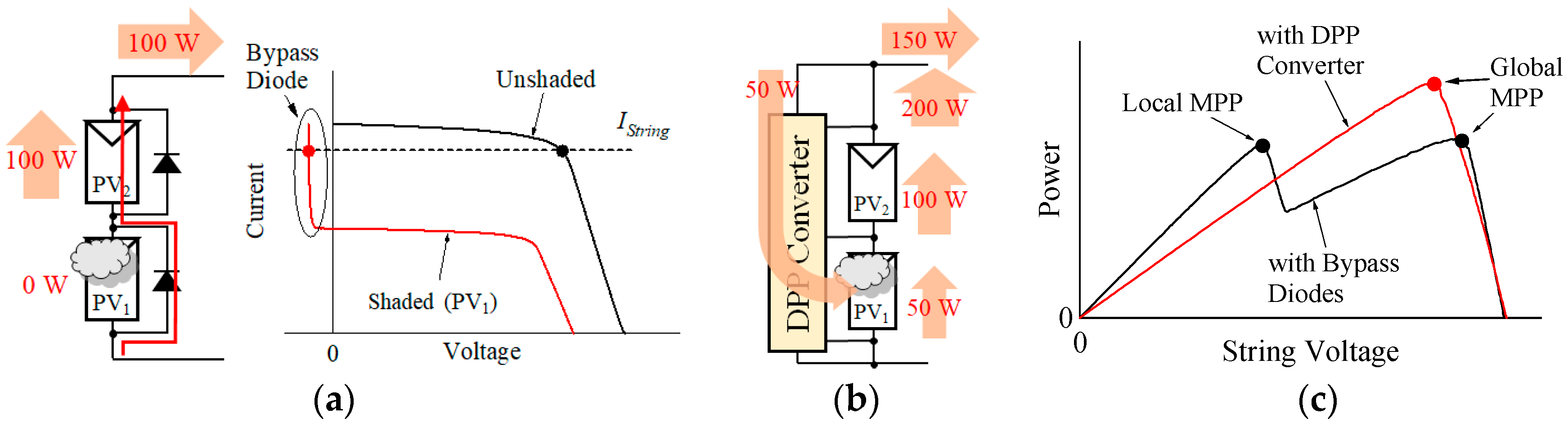
When a partial shading occurs on a photovoltaic (PV) string composed of multiple submodules (hereafter call modules for simplicity), module characteristics vary depending on the irradiance. Since shaded modules generate less current than do unshaded ones, a string current flows through a bypass diode connected in parallel with the shaded modules, as exemplified in Figure 1a, in which a PV string comprising two modules is illustrated. The power generation of the entire string significantly decreases because the shaded module no longer contributes to power generation due to the conduction of the bypass diode. Simulation analysis in past research showed that a partial shading equivalent to 10% of the area of a PV string installed on a residential roof leads to a 20%–30% decrease in the annual energy yield [1]. Furthermore, multiple maximum power points (MPPs), including one global MPP and local MPP(s), occur in P-V characteristics of partially-shaded strings (see Figure 1c), suggesting that ordinary MPP tracking (MPPT) algorithms may malfunction and the string works at a non-optimal point.
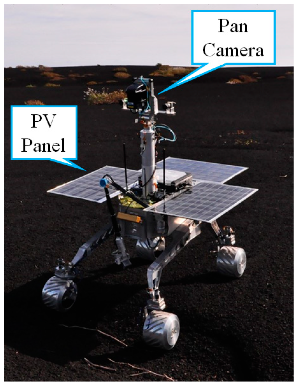
Partial shading is also a serious issue in space exploration rovers. A panning camera mounted on the top of an exploration rover often casts a shadow over PV panels, as shown in Figure 2. The decreased energy yield due to partial shading translates to the increased volume and mass of the PV panel. Since the reduction in volume and mass is the top priority in spacecraft power systems, countermeasures for partial shading are an urgent demand in exploration rovers.
Distributed MPPT systems [2], as well as various kinds of differential power processing (DPP) converters [3,4,5,6,7,8,9,10,11,12,13,14,15,16,17,18,19,20,21,22,23,24], have been proposed to tackle the partial shading issues. DPP converters are a converter that transfer power between adjacent modules or between a string and modules in order to eliminate the adverse effects of partial shading by virtually unifying electrical characteristics of all modules. An example of the power distribution by a DPP converter is depicted in Figure 1b. Suppose PV1 and PV2 are capable of generating 50 and 100 W, respectively, and the DPP converter is ideal with no loss. A fraction of the string power (50 W in this case) is redistributed to the shaded module of PV1 via the DPP converter so that PV1 behaves as if it can generate 100 W with the support of the DPP converter. In addition, since module characteristics are virtually unified by the power redistribution via the DPP converter, a local MPP vanishes and the power yield at the global MPP in the string’s P-V characteristic dramatically increases, as depicted in Figure 1c. In summary, the DPP converter circulates 50 W, and an extractable maximum power is 150 W, significantly enhancing the power yield in comparison with the case of bypass diodes.
Despite the increased power yield under partial shading conditions, DPP converters are required in addition to the main dc-dc converter for string control, increasing the system complexity and cost. In this paper, conventional DPP converters and several kinds of integrated PWM converters that can reduce the system complexity thanks to the integration are reviewed and are quantitatively compared from various aspects. Based on the comparison, a suitable integrated converter topology is selected, and its improved version is also proposed. Finally, the efficacy of the proposed integrated PWM converter will be demonstrated based on the experimental verification tests.
2. Countermeasures for Partial Shading
2.1. Distributed MPPT System
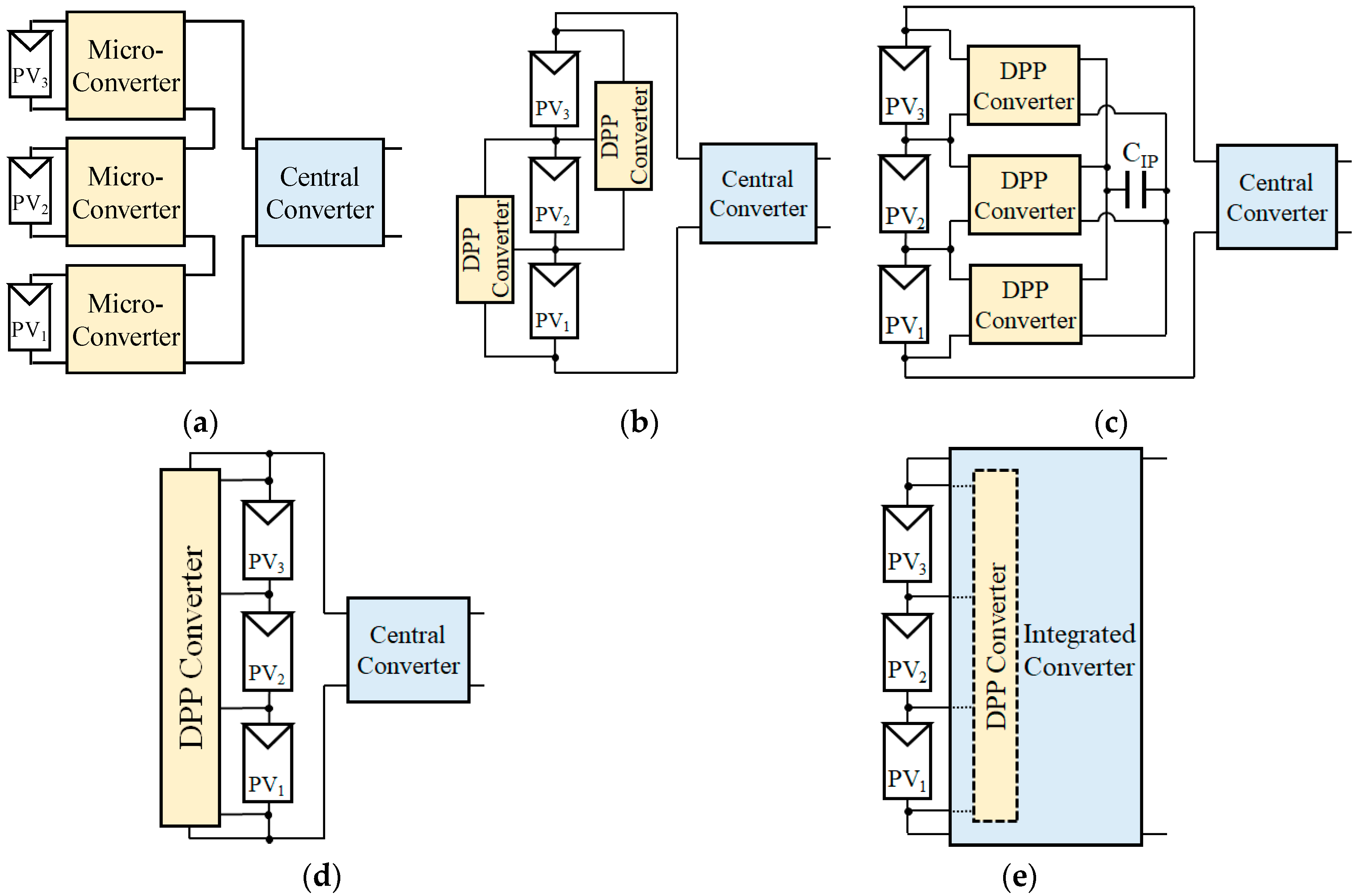
A micro-converter, also known as a dc optimizer (see Figure 3a), is installed for each module to individually perform MPPT control and to extract maximum power from all modules [2]. This system tends to be complicated because it requires as many converters as modules. In addition, since each converter needs to be designed capable of the full power of the module, a larger power rating is required compared to DPP converters described later.
2.2. DPP Converters for Adjacent Modules
DPP converters, which essentially are a bidirectional converter, transfer power between adjacent modules, as shown in Figure 3b, so that electrical characteristics of all modules are artificially unified even under partial shading conditions [3,4,5,6,7,8,9,10,11,12,13,14,15]. Since these DPP converters process only the power difference between adjacent modules, the power rating of the DPP converter can be rather smaller than that of micro-converters [3].
Figure 4 shows typical DPP converter topologies for adjacent modules. In addition to the need for not only a central converter but also multiple DPP converters in proportion to the number of modules, this system is prone to complexity because each DPP converter needs at least two switches for bidirectional power conversion—the switch count can be an indicator of circuit complexity because each switch requires an auxiliary circuit including a gate driver IC and its power supply. In addition, topologies in Figure 4a,b need multiple inductors in proportion to the number of modules, and therefore the circuit tends to be bulky and costly. Furthermore, each DPP converter transfers power only between adjacent modules, and the overall efficiency tends to decrease due to multiple power conversion stages as well as collective power conversion loss [15].
2.3. DPP Converters with Isolated Port
In the architecture using DPP converters with an isolated port (IP) of CIP (see Figure 3c), bidirectional isolated converters, such as flyback converters, are generally employed [16,17,18,19,20]. Power transfer between not only adjacent modules but also remote modules is feasible via the IP, and therefore this architecture is advantageous for long PV strings consisting of numerous modules. However, since the number of DPP converters, each containing at least two switches and one isolation transformer, is equal to the module count, this architecture is prone to be more complex and costlier than the DPP architecture for adjacent modules.
2.4. DPP Converters between String and Modules
A DPP converter in this system transfers power directly from the string to shaded module(s) so that electrical characteristics of all modules are virtually unified to preclude partial shading issues [21,22,23,24]. Since one single DPP converter can handle multiple modules at a time, as shown in Figure 3d, the system can be simpler and less expensive than the aforementioned DPP architectures.
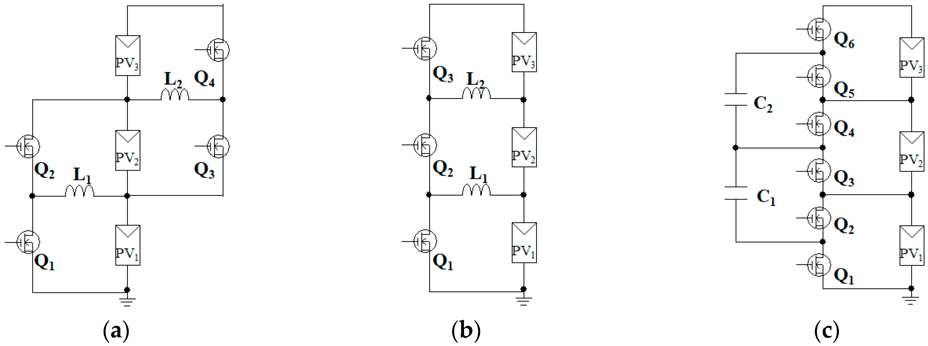
Figure 5 shows representative DPP converter topologies between string and modules. These DPP converters can be configured with a lower switch count when compared to the topologies shown in Figure 4, achieving a simplified circuit. However, in addition to the main converter for string power control, a DPP converter is still separately necessary. In other words, since two separate converters are required, there is room for improvement from the viewpoint of system simplification.
2.5. Integrated Converters
The integrated converter architecture in Figure 3e, which can be derived from sharing circuit parts between two converters, performs both the DPP function and string control [25,26,27,28]. The numbers of circuit parts, as well as converters, can be reduced by the integration, realizing the system simplification, cost reduction, and enhanced reliability. However, since two functions of DPP converter and string power control are integrated into a single unit, performance optimization is no longer feasible. Therefore, energy yield from a PV string tends to be smaller in comparison to the systems using the main converter and DPP converters separately (Figure 3b–d).
3. Requirements for Power System in Small Exploration Rovers
From the viewpoint of electrical performance requirement, there are no significant differences between spacecraft and terrestrial applications. However, given the requirements for power systems in small spacecraft, there are four major aspects that significantly influence selections of electric parts, circuit topologies, and system architectures. In the following, these aspects are discussed and considered.
(1) Simplest possible control circuit due to poor product line-up of rad-hard electrical parts: Radiation-tolerant (or rad-hard) electric parts must be used in converters in spacecraft, and therefore, careful consideration for parts selection and circuit design is mandatory. Specifically, poor product line-up of rad-hard electric parts, especially ICs and micro-controllers, greatly limits the parts selection and circuit design. In terrestrial applications, for example, various kinds of dedicated low-cost ICs and micro-controllers are readily available in the market, and converters relying on complex control techniques can be relatively easily implemented thanks to the low-cost high-performance electric parts. In spacecraft applications, on the other hand, rad-hard ICs and micro-controllers are extremely expensive (e.g., a rad-hard micro-controller costs a few ten thousand dollars) or even unavailable, and hence, control circuits must be often configured using discrete electric parts. Therefore, converters in spacecraft desirably operate with the simplest possible control circuit, and ultimately, a control circuit should be omitted. In other words, converters operable with an open-loop control is an ideal choice.
(2) Reliability improvement by minimizing electric parts count: Since components in the spacecraft cannot be repaired nor replaced after launching, the reliability is always of great importance. The reduction in the electric parts count is the key to improving the reliability, and the reduction of semiconductor switches, which have a complicated structure compared to passive elements, is particularly effective. Furthermore, as described in Section 2.2, since an auxiliary circuit is required to drive each switch, converters that can operate with a few switches will greatly contribute to improving the reliability.
(3) Reduction in volume and mass from circuit viewpoint: Given that the reduction in volume and mass is the top priority in spacecraft electrical systems, bulky circuit parts, such as magnetic components and film capacitors, are desirably eliminated from converters.
(4) Reduction in volume and mass from system architecture viewpoint: In the conventional medium- to large-scale spacecraft of several hundred watt to several kilo-watt classes, PV panels occupy a large portion of a total mass in spacecraft power systems. To reduce the total mass, spacecraft power systems are designed such that the energy yield from PV panels is maximized. In other words, a power system having a main dc-dc converter and DPP converter separately (Figure 3b–d) would be a desirable power system architecture for medium- to large-scale spacecraft—the main dc-dc converter and DPP converter can be individually optimized in the architecture in Figure 3b–d. In small-scale spacecraft, on the other hand, the relative mass of PV panels is not significant, and the reduction in the number of components is the most effective approach to achieve the total mass reduction. Therefore, integrated converters that can reduce the number of components is advantageous in small spacecraft applications.
The next subsection focuses only on integrated converters to select a topology suitable for small exploration rovers.
4. Integrated PWM Converters
As discussed in the previous section, integrated converters are suitable for small exploration rovers from the viewpoint of the reduction in volume and mass of the system. Meanwhile, converters operable with an open-loop control are ideal from the viewpoint of the rad-hard electric parts selection. This section introduces integrated PWM converter topologies that do not need feedback control for DPP functions. In other words, all the integrated converter topologies in this section meet the requirement regarding (1) and (4) discussed in Section 3.
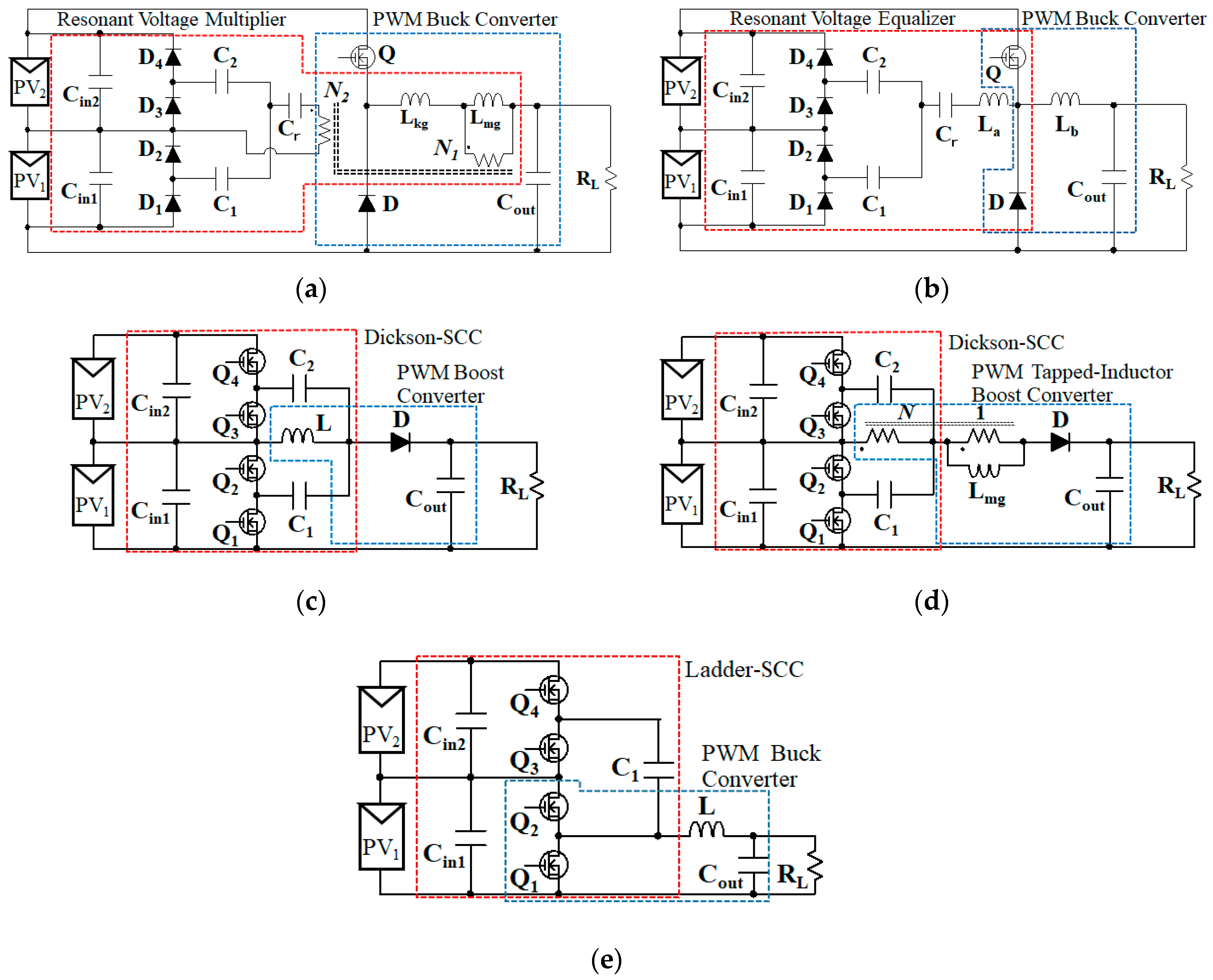
Figure 6a–e shows the five integrated PWM converter topologies for two PV modules connected in series. All topologies can perform both the DPP function and string power control at a time, but each topology has unique advantages and drawbacks depending on the foundation circuit.
4.1. Single-Switch Single-Magnetic PWM Converter with Resonant Voltage Multiplier
This topology is derived based on the combination of a resonant voltage multiplier (RVM) [25,26] and a PWM buck converter, as shown in Figure 6a. The magnetizing inductance Lmg of the transformer acts as a filter inductor of the PWM buck converter. The square wave voltage generated across the secondary winding drives the RVM circuit that plays a role of the DPP converter. The single-switch single-magnetic topology realizes a simple and compact circuit.
4.2. Single-Switch Transformerless PWM Converter with Resonant Voltage Multiplier
Similar to the topology in Section 4.1, the RVM is driven by the square wave voltage generated in the PWM buck converter. Since two inductors are required (Figure 6b), this integrated converter would be bulkier than the single-switch single-magnetic integrated converter introduced in the previous subsection.
The RVM in this integrated converter always operates regardless of the occurrence of partial shading. Since the operation of the RVM causes unnecessary losses under unshaded conditions, this integrated converter is considered suitable for small spin satellites where partial shading always occurs.
4.3. Dickson-SCC-Based PWM Converter
This topology (Figure 6c) is derived from the combination of a Dickson switched capacitor converter (SCC) and a PWM boost converter [28]. The negative influences of partial shading are precluded by the Dickson SCC that equalizes module voltages automatically. Odd- and even-numbered switches are alternately driven so that power is transferred between adjacent modules [11]. A large number of switches are necessary, and therefore the circuit is prone to complexity in comparison to the single-switch topologies, likely reducing the reliability due to the increased number of circuit parts. On the other hand, there is only one inductor and its stored energy is partly shared by capacitors, and hence the inductor can be significantly downsized [29,30].
This SCC-based topology allows significant circuit miniaturization compared with the single-switch topologies and thus is suitable for micro- and nano-satellites that prioritize system miniaturization rather than the reliability.
4.4. Dickson-SCC-Based Tapped-Inductor PWM Converter
This is an extended version of the Dickson-SCC-based converter discussed in Section 4.3. A tapped-inductor is introduced as an extra design freedom to adjust a voltage conversion ratio, as shown in Figure 6d.
4.5. Ladder-SCC-Based PWM Buck Converter
The ladder-SCC-based integrated PWM buck converter, shown in Figure 6e, is the combination of a ladder-SCC and a PWM buck converter [27]. Similar to the Dickson-SCC-based topologies, the circuit miniaturization is feasible thanks to capacitors. In comparison with the Dickson-SCC-based topologies in Figure 6c,d, the capacitor count can be slightly reduced, achieving a simpler and less expensive circuit.
5. Comparison and Selection of Integrated Converter for Small Exploration Rovers
In the integrated converters with the RVM or SCC introduced in Section 4, controlling the PWM converter only automatically realizes the DPP function. In other words, both the RVM and SCC circuits can perform the DPP function with open-loop control and, therefore, are suitable for spacecraft power systems as these topologies meet the requirement regarding (1) and (4) discussed in Section 3. Hence, in the following, integrated converter topologies are compared from the viewpoint of the reliability and volume (i.e., the points of (2) and (3) in Section 3).
As mentioned in Section 2.2, the switch count is an indicator of circuit complexity, and converters with fewer switches are a desirable topology from the viewpoint of the reliability. Meanwhile, since the magnetic components are the bulkiest circuit element in converters, the magnetic component count can be regarded as an indicator of the circuit volume and mass. Needless to say, converters must meet the requirement of voltage conversion ratios necessary in specific applications. With these aspects taken into consideration, the quantitative comparison is made from the viewpoints of the switch count, magnetic component count, and voltage conversion ratio (Vload/Vstring).
Table 1 compares the five kinds of integrated PWM converters introduced in Section 4. Vstring is an input voltage, Vload is a load voltage, and d is a duty cycle of switches. N is the turn ratio of the tapped-inductor.
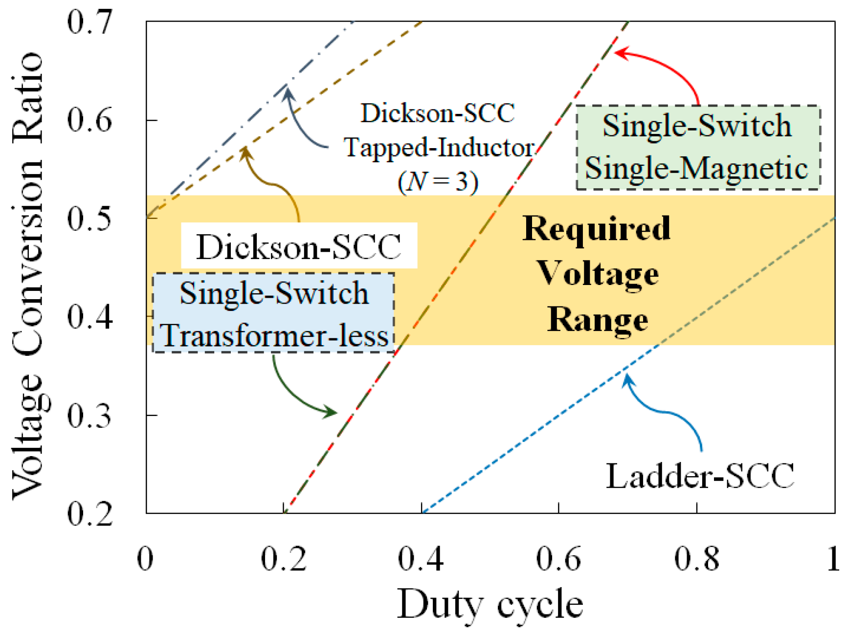
The electrical requirement in small exploration rovers is described below. A PV panel consists of two modules connected in series, and its voltage Vstring is 16 V (VPV = 8.0 V). Two lithium-ion battery cells connected in series are directly connected to the load, and Vload varies in the range of 6.0–8.4 V. From the given values of Vstring and Vload, the required voltage conversion ratio is 0.375–0.525.
Figure 7 shows and compares the voltage conversion ratios of the five integrated PWM converters as a function of the duty cycle. Two types of single-switch integrated converters (i.e., the single-switch single-magnetic converter and single-switch transformer-less converter) meet the voltage conversion requirement in the entire range, whereas voltage conversion ratios of SCC-based integrated converters are out of the required range. Based on the pairwise comparison between the two single-switch integrated PWM converters, the single-switch single-magnetic topology is advantageous in terms of the magnetic component count. In addition, partial shading does not always occur in exploration rovers, unlike the spin satellites where some portion of PV panels is always shaded, the single-switch single-magnetic integrated converter is also advantageous in terms of power conversion efficiency under unshaded conditions—in the single-switch transformerless topology, currents unnecessarily flow toward substrings even under unshaded conditions, generating unnecessary losses. The above comparison and discussion conclude that the single-switch single-magnetic integrated PWM converter is the best suitable topology for small exploration rovers.
6. Operation Analysis for Single-Switch Single-Magnetic Integrated PWM Converter with Non-Resonant Voltage Multiplier
6.1. Circuit Description and Its Features
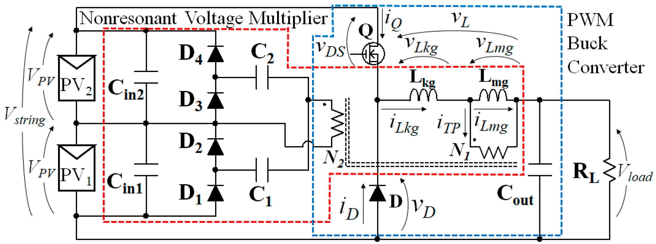
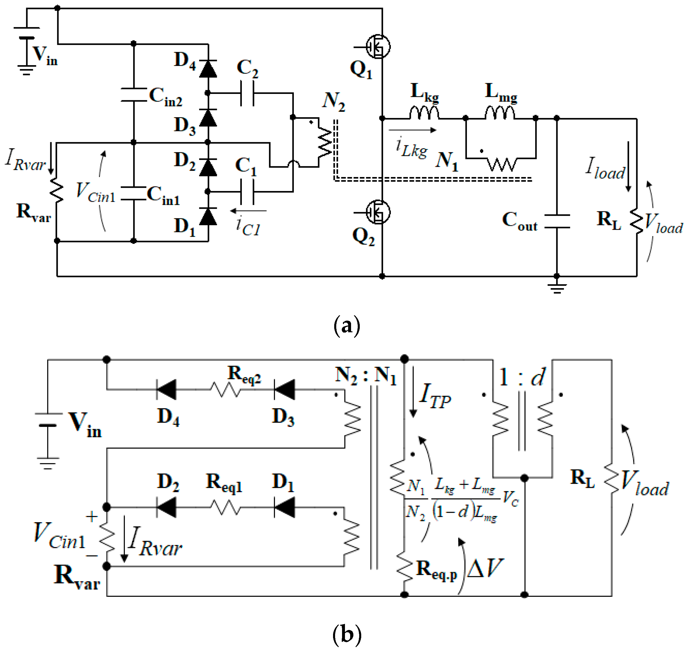
The conventional single-switch single-magnetic integrated PWM converter with the RVM requires a resonant capacitor Cr for its resonant operation, as shown in Figure 6a. In general, a film capacitor is used for Cr because its capacitance must be accurate and independent on a bias voltage. However, as discussed in Section 3, film capacitors are relatively bulky and are desirably omitted from circuits to achieve reduced circuit volume and mass. In this paper, we propose an integrated PWM converter with a non-resonant voltage multiplier (NRVM), as shown in Figure 8, where Cr is eliminated to further simplify and miniaturize the circuit and to further improve the reliability. The proposed topology is a non-isolated dc-dc converter that can also be applied to standalone PV systems, not only to space applications.
In the conventional integrated PWM converter with the RVM (see Figure 6a), the current in the RMV is a discontinuous sinusoidal wave, and hence, Joule losses tend to be large due to relatively large peak currents. In the proposed integrated PWM converter with the NRVM, on the other hand, the current in the NRVM is a continuous triangular wave (see Figure 9), and the current continuity helps reduce the peak currents and Joule losses, compared to the conventional RVM. Current waveforms of the NRVM and RVM will be compared in Section 6.3.
Unlike the conventional RVM, characteristics of the NRVM are dependent on the duty cycle of the switch Q. In other words, the DPP function of the NRVM varies with the duty cycle, and the characteristics of the NRVM need to be modeled in order to accurately estimate behaviors of a PV panel supported by the NRVM under partial shading conditions. In the next section, the mathematical model of the NRVM will be derived based on the detailed operation analysis.
6.2. Operation Analysis
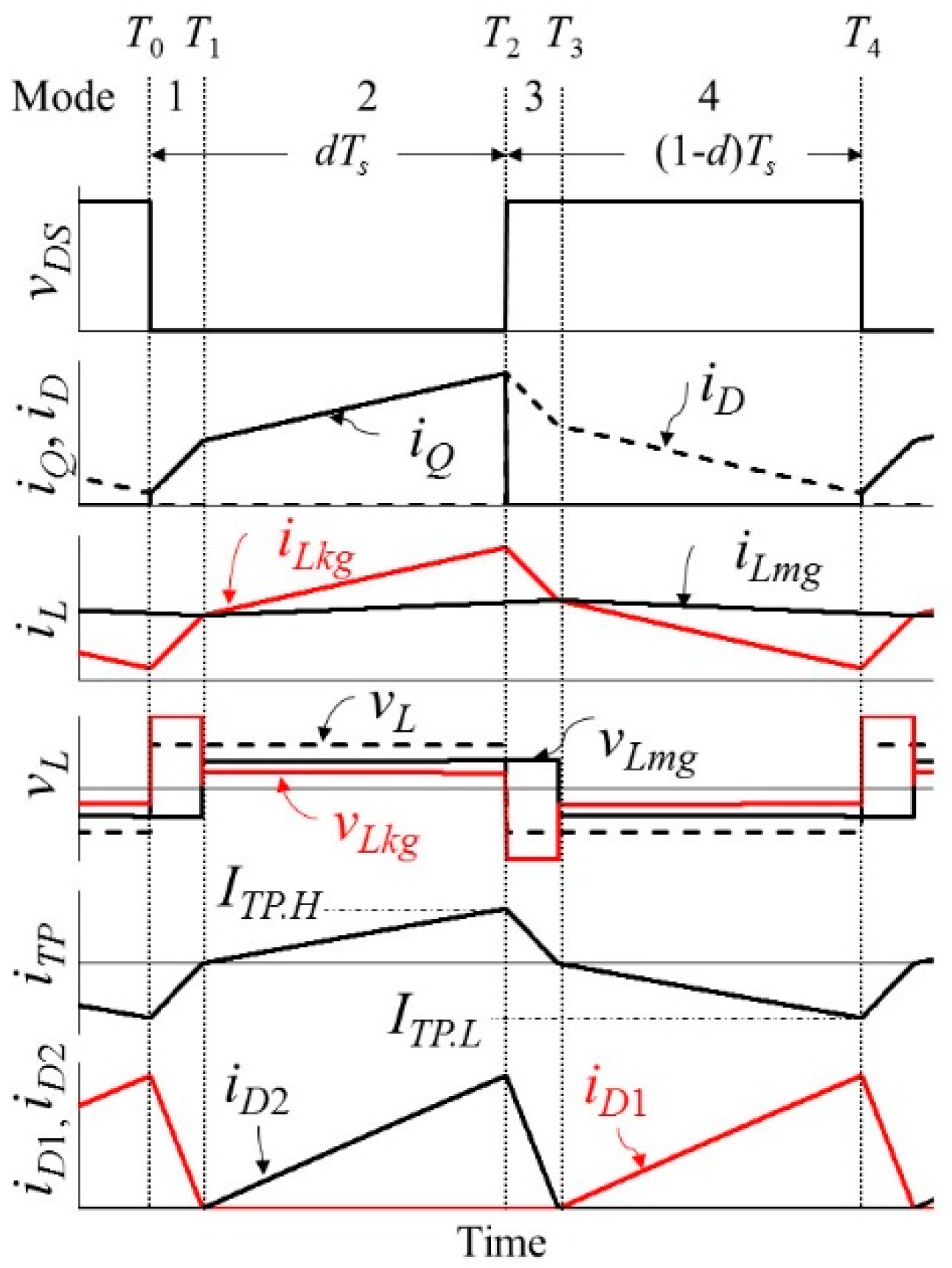
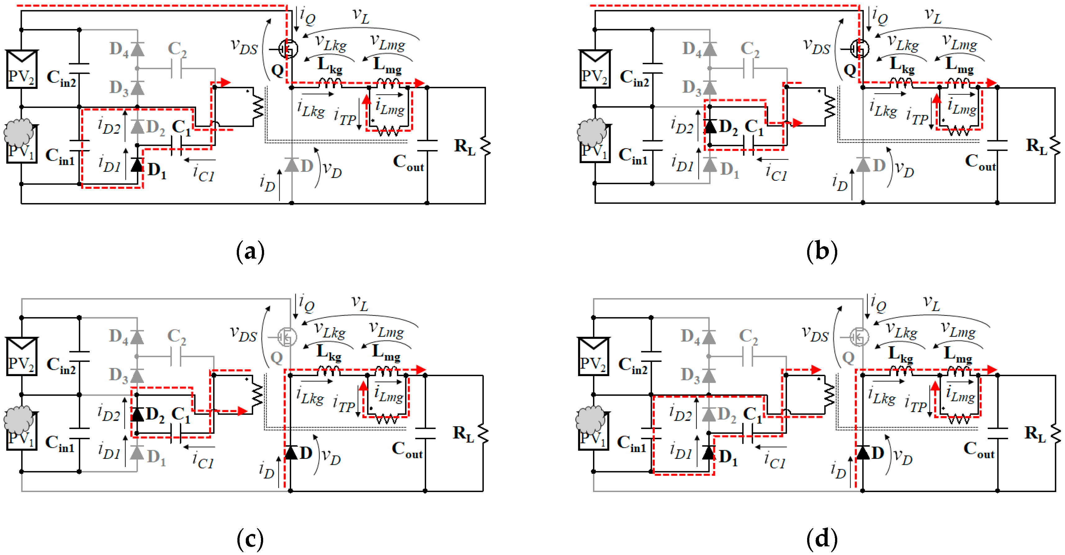
The operation analysis is performed for a representative case that PV1 is partially shaded. Key operation waveforms and current flow paths are shown in Figure 9 and Figure 10, respectively. Ts in Figure 9 is the switching period. The fundamental operating principle is identical to that of an ordinary PWM buck converter. The analysis in this section is performed based on the premise that all circuit parts are ideal, and a time constant τ formed by Lkg and C1 or C2 is far longer than the switching period so that iLkg is assumed to change linearly.
Mode 1 (T0 < t ≤ T1) (Figure 10a): The voltage across the primary winding of the transformer vL is equal to Vstring − Vload. In the NRVM, the current of C1, iC1, flows through the low-side diode D1. The current flowing through the primary winding iTP corresponds to the difference between the current of the leakage inductance iLkg and the current of the magnetizing inductance iLmg. Since the primary winding current can be obtained from the voltages of Lkg and Lmg, vLkg and vLmg, respectively, iTP in Mode 1 can be expressed as
where VC1, d, and ITP.L are the average voltage of C1, the duty cycle of Q, and the initial current of iTP in Mode 1, respectively.
Mode 2 (T1 < t ≤ T2) (Figure 10b): Q is still on, so vL is the same as that in Mode 1. The high-side diode D2 starts conducting on the transformer secondary side. Meanwhile, vLkg and vLmg change as the direction of iC1 is reversed on the secondary side. iTP in Mode 2 is expressed as
Mode 3 (T2 < t ≤ T3) (Figure 10c): Q is turned off and vL = −Vout, but D2 is still conducting. The polarity of vLkg is reversed as the current flow path on the primary side changes. iTP in Mode 3 is given by
where ITP.H is the initial current of iTP in Mode 3, as designated in Figure 8.
Mode 4 (T3 < t ≤ T4) (Figure 10d): D1 begins to conduct again. The polarities of both the vLkg and vLmg change as the current flow path on the secondary side changes. iTP in Mode 4 is expressed as
Based on Equations (2) and (4), ITP.L and ITP.H in Equations (1) and (3) can be yielded as
where td is a length of Mode 1, and ((1 − d)/d)td corresponds to the period of Mode 3. This is derived from the relationship of d: td = (1 − d): T32, assuming the period of Mode 3 to be T32 [31].
The current of C1 in each mode is given by the following equation using the transformer turns ratio and iTP, as
where the subscript number m = 1…4 is the mode number. As the average voltage of the transformer winding must be zero, the average voltage of C1, VC1, is given by
Since the average current of C1 under steady-state conditions is zero, the current supplied to the shaded module, IVM, is equal to the average current of D1 and D2. Therefore, IVM can be expressed as
where ΔV is given by
6.3. Waveform Comparison between NRVM and Conventional RVM
Current waveforms of iTP in the proposed NRVM and conventional RVM are compared in Figure 11—iTP is taken for the comparison because it represents all currents in the voltage multiplier. iTP in the conventional RVM is a discontinuous sinusoidal wave and its peak value Ipeak.RVM tends to be large due to the discontinuity. On the other hand, iTP in the NRVM is a continuous triangular wave and its peak value Ipeak.NRVM can be smaller than Ipeak.RVM. The reduced peak current in the proposed NRVM reduces Joule losses in the voltage multiplier, eventually resulting in increased power yield from the PV panel. The increased power yield by the NRVM will be experimentally demonstrated in Section 7.3.
6.4. DC Equivalent Circuit
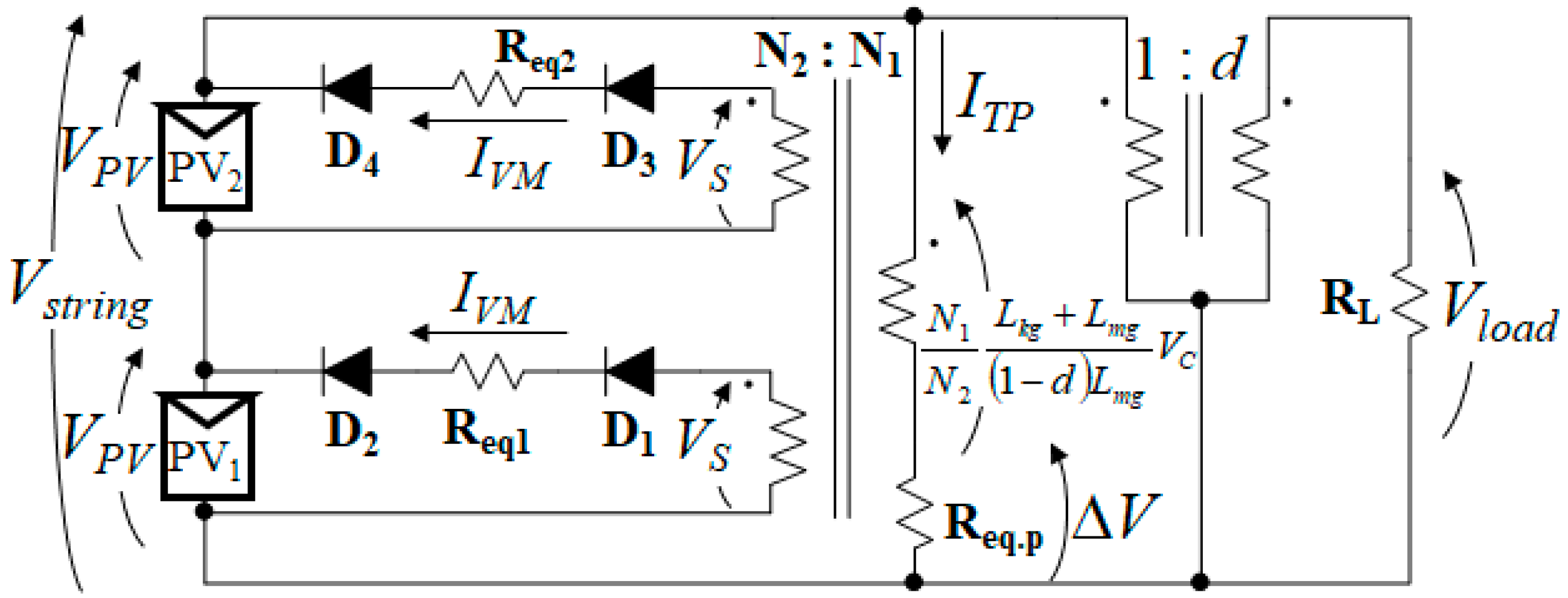
In the past work, the dc equivalent circuit of the single-switch single-magnetic integrated PWM converter with the RVM has been derived [25], as shown in Figure 12. The ideal transformer with the turn ratio of 1:d represents the PWM buck converter. The circuit consisting of the ideal multi-winding transformer, diodes, and equivalent resistors (Req1 and Req2) corresponds to the RVM. In this section, the equivalent resistance in the dc equivalent circuit of the NRVM is derived.
Equation (10) represents the voltage relationship on the primary winding of the ideal multi-winding transformer. ΔV is the voltage drop across the equivalent resistance Req.p, and the second term on the right-hand side is the reflected voltage across the primary winding. Based on Equations (7), (9), and (10), the average absolute value of iTP, ITP, can be obtained. Assuming ΔV as the voltage drop due to the equivalent resistance, the following equation is yielded
From Equation (11), the equivalent resistance Req.p existing on the primary side of the ideal multi-winding transformer is given by
Next, to derive the equivalent resistance Req1 of the NRVM, the voltage variation of C1 is considered based on [32]. Let VC1.D1 be the voltage of C1 in Modes 1 and 4, during which D1 conducts. Similarly, VC1.D2 is the voltage of C1 when D2 conducts in Modes 2 and 3. VC1.D1 and VC1.D2 can be expressed as
where Vs.p and Vs.n are the secondary winding voltage in each mode, r is the total resistance of the current path in the NRVM, and Vf is the forward voltage drop of a diode. The voltage variation of C1, ΔVC1, is given by
Since IVM is a current rectified by the NRVM,
From Equations (14) and (15),
Rearrangement of Equation (16) produces
From Equation (17), the equivalent resistance Req1 is obtained as
6.5. Operation Conditions of NRVM
The output voltage of the NRVM is equal to the peak-to-peak value of the voltage applied to the secondary winding, and the voltage applied to each module is ideally (N2/N1)Vstring [25]. If (N2/N1)Vstring is lower than the module voltage VPV, the NRVM is inactive. Therefore, considering the forward voltage drop of diodes Vf, the transformer turn ratio needs to satisfy the following equation
7. Experimental Results
7.1. Prototype
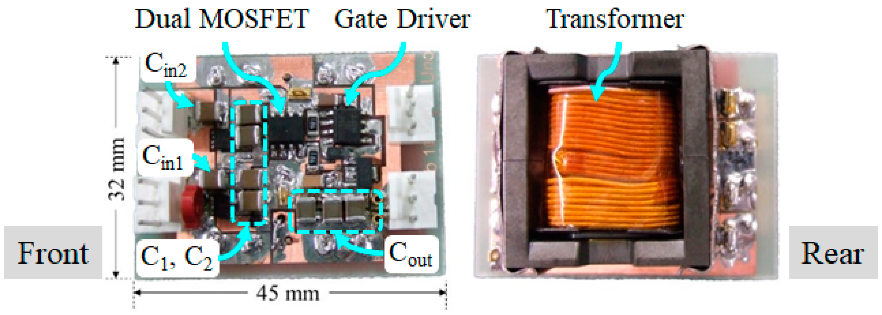
A 30-W prototype of the proposed integrated PWM converter with the NRVM for two modules connected in series was built, as shown in Figure 13. Table 2 shows the circuit parts used for the prototype. The switching frequency was 100 kHz. For the sake of experimental convenience, a MOSFET was used instead of the free-wheeling diode D, and the prototype was operated in a synchronous mode. The power conversion efficiency at the full load of 30 W under an unshaded condition was measured to be as high as 93%.
7.2. Output Characteristics of NRVM
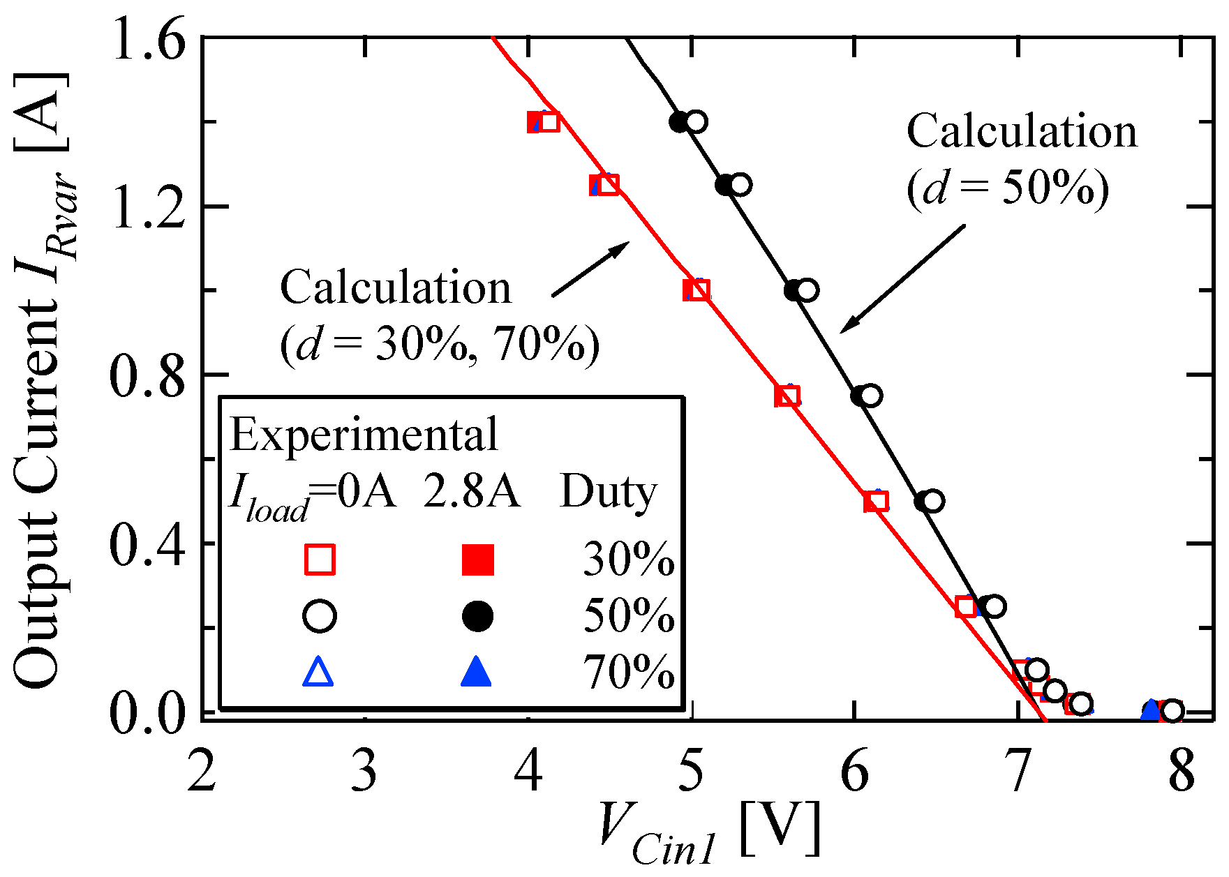
The characteristics of the NRVM were measured using the experimental setup shown in Figure 14a. An external power supply Vin of 16 V was used, instead of PV modules. A variable resistor Rvar was connected in parallel with Cin1 to simulate the current flow paths under the PV1-shaded condition. VCin1 and IRvar were measured while changing Rvar. The load resistance RL was adjusted so that Iload was 0 or 2.8 A. iLkg and iC1 were measured using a current probe (TCP312A, Tektronix, Portland, OR, USA)—Litz wires were inserted in series with the transformer’s primary winding and C1 in order to measure the currents. To verify the derived model in Section 6, the output characteristics of the NRVM were calculated based on the dc equivalent circuit shown in Figure 14b. Conditions and circuit parameters were identical to those of the experiment, while r in (18) was set to be 140 mΩ based on the experimentally-measured resistance.
The measured and calculated characteristics are shown and compared in Figure 15. The experimental results satisfactorily matched with the calculations, verifying the mathematical model derived in Section 6. VCin1 linearly decreased as IRvar increased. IRvar was nearly 0 A in the region where VCin1 was higher than 7.3 V. From the provided values in Table 2 (N2/N1 = 0.5 and Vf = 0.435 V), this result verified that IRvar flowed only in the range where Equation (19) was satisfied. VCin1 with d = 30% and 70% decreased steeper than that with d = 50% due to the increased equivalent resistance Req.p—Equation (12) implies that Req.p increases as d moves away from 50%. On the other hand, the measured characteristics were nearly independent on Iload, suggesting that the characteristics of the NRVM were not influenced by load currents.
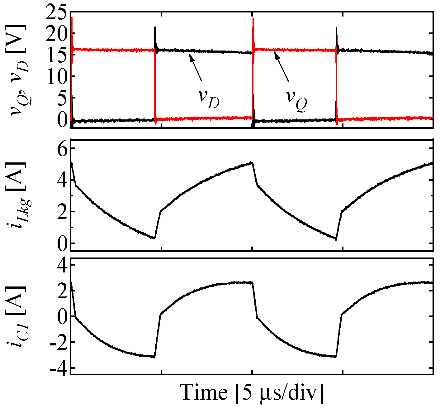
Measured key waveforms at Vload = 8.0 V and Iload = 2.8 A are shown in Figure 16. The measured current waveforms were slightly blunt, not completely linear, because of a time constant τ of L/R formed by Lkg and resistive components of the diode and secondary winding. Although slightly different from the theoretical waveforms in Figure 9, the measured waveforms showed a good agreement, verifying the operation of the prototype.
7.3. Experiments Emulating Partial Shading Condition
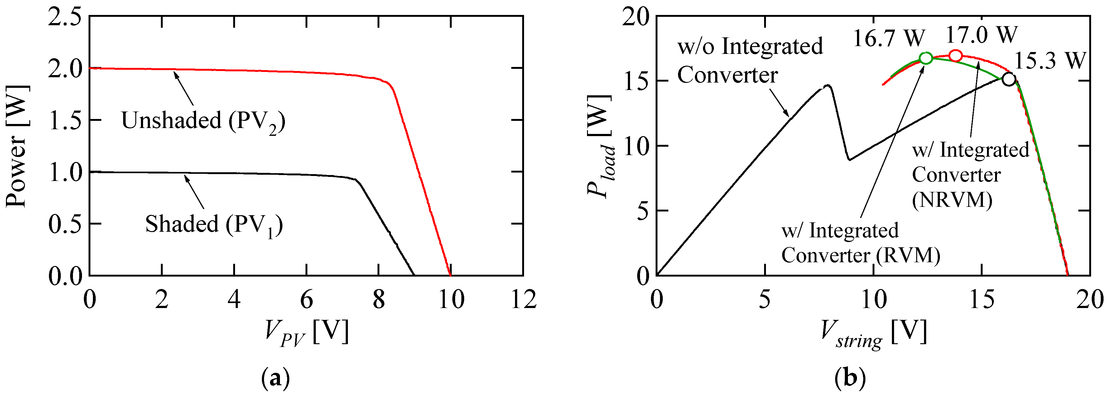
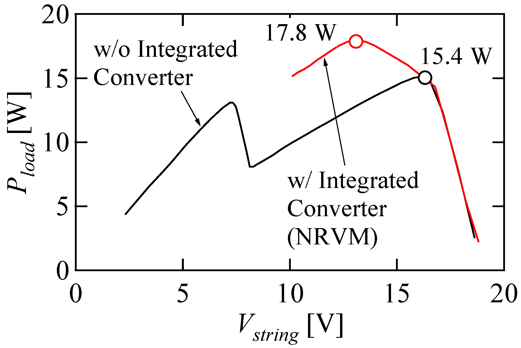
String characteristics with/without the prototype were measured under a partial shading condition. Solar array simulators (E4361A, Keysight Technologies, Santa Rosa, CA, USA) were used to emulate a partial shading condition. The electrical characteristics of the modules used in the experiment are shown in Figure 17a. The short-circuit current of PV1 was set to be half of PV2, assuming the case that PV1 was severely shaded. String characteristics were measured under three cases: (1) with the proposed integrated converter with the NRVM, (2) with the conventional integrated converter with the RVM, (3) without the integrated converter (i.e., with traditional bypass diodes).
As for case (1), a constant voltage load of 8.0 V was used as RL, and d was manually varied in the range of d ≤ 0.8 in order to sweep the string characteristics. For case (2), in order to compare the performances of the proposed NRVM and conventional RVM, the prototype was retrofitted to be the conventional integrated converter with the RVM by inserting a resonant capacitor Cr (ECWU1105KCV, 1 μF × 3 parallel) in series with the secondary winding. The resonant frequency was 182 kHz. The conditions of d and the load voltage in case (2) were identical to those in case (1). In case (3), the integrated converter was removed, and the string characteristic was swept between zero and the open-circuit voltage by directly connecting an electronic load to the string.
The measured string characteristics are shown and compared in Figure 17b. Without the integrated converter, there were two MPPs observed in the measured P–V characteristic, and the maximum power at the global MPP was merely 15.3 W at Vstring = 16.2 V. In this case, the shaded module PV1 was bypassed and did not contribute to power generation, similar to the case shown in Figure 1a. Meanwhile, with the integrated converters, Vstring was swept in the range between 10.5 V and the open-circuit voltage of 19 V, corresponding to the duty cycle variation of d ≤ 0.8. In the region of Vstring > 16.5 V, in which Equation (19) was not satisfied, the NRVM did not operate, and therefore, the measured Pload characteristics were independent on whether the integrated converter was used. In the region of Vstring < 16.5 V, on the other hand, Pload was significantly improved by the integrated converter because a fraction of the string power was redistributed to the shaded module of PV1—this power redistribution scenario is identical to the case discussed in Section 6.2. With the integrated converter with the NRVM, the maximum power increased to as high as 17.0 W at Vstring = 13.7 V, corresponding to 11.1% improvement in the power yield. Meanwhile, the measured maximum power with the conventional RVM was 16.7 W at Vstring = 12.4 V, corresponding to a 9.2% improvement. The slightly-inferior power yield of 1.9 points was attributable to the increased Joule loss due to the relatively large peak resonant current, as compared in Figure 11.
In summary, with the integrated converter, the local MPP successfully vanished, and the power yield drastically increased. These results demonstrated the superior performance of the proposed integrated PWM converter with the NRVM.
7.4. Verification for DC Equivalent Circuit
A simulation-based test using the dc equivalent circuit was also performed emulating the partial shading condition identical to that of the experiment. PV module characteristics were emulated by look-up tables. Req.p in the equivalent circuit was programmed to obey Equation (12).
The string characteristics with/without the dc equivalent circuit of the integrated converter (see Figure 12) are shown in Figure 18. The simulation results slightly differed from the experimental characteristics shown in Figure 17b probably because resistive components were ignored to simplify the analysis and the derivation of the dc equivalent circuit. However, the simulation and experimental results satisfactorily matched, indicating the validity of the derived dc equivalent circuit.
8. Conclusions
PV strings in small exploration rovers suffer from partial shading issues because of a panning camera mounted on the top of the exploration rovers. Solutions to the partial shading issues, including conventional DPP architectures and topologies, were reviewed from various aspects, such as electrical parts count and circuit volume. Integrated DPP converters, which can reduce the component count by the integration, are an attractive architecture in small exploration rovers where the reduction in the number of components is the most effective approach to achieve the total mass reduction. Hence, integrated DPP converters only were focused on the following review and comparison.
Several types of PWM converters integrating DPP converters were reviewed, and the quantitative comparison was made for the switch count, the magnetic component count, and the voltage conversion ratio, with considering the requirements of power systems in small exploration rovers. The single-switch single magnetic integrated PWM converter with the RVM was selected as the best suitable topology because of its circuit simplicity and less magnetic component count.
The improved integrated PWM converter with the NRVM that eliminates a bulky film capacitor was also proposed to achieve further circuit miniaturization and improved reliability. Furthermore, the reduced peak current thanks to the non-resonant operations of the NRVM achieves improved power conversion efficiency. The detailed operation analysis was performed to derive the mathematical model, followed by the derivation of the dc equivalent circuit.
The experimental verification tests using the 30-W prototype of the integrated PWM converter with the NRVM or the conventional RVM were performed emulating the partial shading condition. In comparison with the case of traditional bypass diodes, the integrated converters with the NRVM and RVM improved the power yield by 11.1% and 9.2%, respectively, demonstrating its efficacy. The slightly-superior power yield of 1.9 points was attributable to the reduced Joule loss thanks to the lower peak currents by the non-resonant operations of the NRVM. The experimental results satisfactorily matched with the simulation results of the derived dc equivalent circuit, verifying the mathematical model obtained from the operation analysis.
Author Contributions
Conceptualization, M.U.; methodology, M.U. and T.S.; simulation analysis, T.S. and Y.S.; validation, T.S. and Y.S.; writing—original draft preparation, M.U. and T.S.; writing—review and editing, M.U.; supervision, M.U. and A.K.
Funding
This research received no external funding.
Conflicts of Interest
The authors declare no conflict of interest.
References
- MacAlpine, S.M.; Erikson, R.W.; Brandemuehl, M.J. Characterization of power optimizer potential to increase energy capture in photovoltaic systems operating under nonuniform conditions. IEEE Trans. Power Electron. 2013, 28, 2936–2945. [Google Scholar] [CrossRef]
- Vitelli, M. On the necessity of joint adoption of both distributed maximum power point tracking and central maximum power point tracking in PV systems. Prog. Photovolt. Res. Appl. 2014, 22, 283–299. [Google Scholar] [CrossRef]
- Kim, K.A.; Shenoy, P.S.; Krein, P.T. Converter rating analysis for photovoltaic differential power processing systems. IEEE Trans. Ind. Electron. 2015, 30, 1987–1997. [Google Scholar] [CrossRef]
- Shenoy, P.S.; Kim, K.A.; Johnson, B.B.; Krein, P.T. Differential power processing for increased energy production and reliability of photovoltaic systems. IEEE Trans. Ind. Power Electron. 2013, 28, 2968–2979. [Google Scholar] [CrossRef]
- Bergveld, H.J.; Büthker, D.; Castello, C.; Doorn, T.; Jong, A.D.; Otten, R.V.; Waal, K.D. Module-level dc/dc conversion for photovoltaic systems: The delta-conversion concept. IEEE Trans. Power Electron. 2013, 28, 2005–2013. [Google Scholar] [CrossRef]
- Zaman, M.S.; Wen, Y.; Fernandes, R.; Buter, B.; Doorn, T.; Dijkstra, M.; Bergveld, H.J.; Trescases, O. A cell-level differential power processing IC for concentrating-PV systems with bidirectional hysteretic current-mode control and closed-loop frequency regulation. IEEE Trans. Power Electron. 2015, 30, 7230–7244. [Google Scholar] [CrossRef]
- Qin, S.; Cady, S.T.; García, A.D.D.; Podgurski, R.C.N.P. A distributed approach to maximum power point tracking for photovoltaic submodule differential power processing. IEEE Trans. Power Electron. 2015, 30, 2024–2040. [Google Scholar] [CrossRef]
- Qin, S.; Barth, C.B.; Podgurski, R.C.N.P. Enhancing microinverter energy capture with submodule differential power processing. IEEE Trans. Power Electron. 2016, 31, 3575–3585. [Google Scholar] [CrossRef]
- Shimizu, T.; Hashimoto, O.; Kimura, G. A novel high-performance utility-interactive photovoltaic inverter system. IEEE Trans. Power Electron. 2003, 18, 704–711. [Google Scholar] [CrossRef] [Green Version]
- Shimizu, T.; Hirakata, M.; Kamezawa, T.; Watanabe, H. Generation control circuit for photovoltaic modules. IEEE Trans. Power Electron. 2001, 16, 293–300. [Google Scholar] [CrossRef] [Green Version]
- Stauth, J.T.; Seeman, M.D.; Kesarwani, K. Resonant switched-capacitor converters for sub-module distributed photovoltaic power management. IEEE Trans. Power Electron. 2013, 28, 1189–1198. [Google Scholar] [CrossRef]
- Chang, A.H.; Avestruz, A.T.; Leeb, S.B. Capacitor-less photovoltaic cell-level power balancing using diffusion charge redistribution. IEEE Trans. Power Electron. 2015, 30, 537–546. [Google Scholar] [CrossRef]
- Blumenfeld, A.; Cervera, A.; Peretz, M.M. Enhanced differential power processor for PV systems: Resonant switched-capacitor gyrator converter with local MPPT. IEEE J. Emerg. Sel. Top. Power Electron. 2014, 2, 883–892. [Google Scholar] [CrossRef]
- Uno, M.; Saito, Y.; Yamamoto, M.; Urabe, S. PWM switched capacitor-based cell-level power balancing converter utilizing diffusion capacitance of photovoltaic cells. IEEE Trans. Power Electron. 2019, in press. [Google Scholar] [CrossRef]
- Poshtkouhi, S.; Biswas, A.; Trescases, O. Dc-dc converter for high granularity, sub-string MPPT in photovoltaic applications using a virtual-parallel connection. In Proceedings of the 27th Annual IEEE Applied Power Electronics Conference and Exposition (APEC), Orlando, FL, USA, 5–9 February 2012; pp. 86–92. [Google Scholar]
- Olalla, C.; Clement, D.; Rodríguez, M.; Makisimović, D. Architectures and control of submodule integrated dc-dc converters for photovoltaic applications. IEEE Trans. Power Electron. 2013, 28, 2980–2997. [Google Scholar] [CrossRef]
- Olalla, C.; Deline, C.; Clement, D.; Levron, Y.; Rodríguez, M.; Makisimović, D. Performance of power limited differential power processing architectures in mismatched PV systems. IEEE Trans. Power Electron. 2015, 30, 618–631. [Google Scholar] [CrossRef]
- Bell, R.; Podgurski, R.C.N.P. Decoupled and distributed maximum power point tracking of series-connected photovoltaic submodules using differential power processing. IEEE J. Emerg. Sel. Top. Power Electron. 2015, 3, 881–891. [Google Scholar] [CrossRef]
- Levron, Y.; Clement, D.R.; Choi, B.; Olalla, C.; Maksimovic, D. Control of submodule integrated converters in the isolated-port differential power-processing photovoltaic architecture. IEEE J. Emerg. Sel. Top. Power Electron. 2014, 2, 821–832. [Google Scholar] [CrossRef]
- Chu, G.; Wen, H.; Jiang, L.; Hu, Y.; Li, X. Bidirectional flyback based isolated-port submodule differential power processing optimizer for photovoltaic applications. Sol. Energy 2017, 158, 929–940. [Google Scholar] [CrossRef] [Green Version]
- Du, J.; Xu, R.; Chen, X.; Li, Y.; Wu, J. A novel solar panel optimizer with self-compensation for partial shadow condition. In Proceedings of the 28th Annual IEEE Applied Power Electronics Conference and Exposition (APEC), Long Beach, CA, USA, 17–21 March 2013; pp. 92–96. [Google Scholar]
- Uno, M.; Kukita, A. Single-switch voltage equalizer using multi-stacked buck-boost converters for partially-shaded photovoltaic modules. IEEE Trans. Power Electron. 2015, 30, 3091–3105. [Google Scholar] [CrossRef]
- Uno, M.; Kukita, A. Current sensorless equalization strategy for a single-switch voltage equalizer using multistacked buck–boost converters for photovoltaic modules under partial shading. IEEE Trans. Ind. Electron. 2017, 53, 420–429. [Google Scholar] [CrossRef]
- Uno, M.; Kukita, A. Two-switch voltage equalizer using an LLC resonant inverter and voltage multiplier for partially-shaded series-connected photovoltaic modules. IEEE Trans. Ind. Appl. 2015, 51, 1587–1601. [Google Scholar] [CrossRef]
- Uno, M.; Kukita, A. Single-switch single-magnetic PWM converter integrating voltage equalizer for partially-shaded photovoltaic modules in standalone applications. IEEE Trans. Power Electron. 2018, 33, 1259–1270. [Google Scholar] [CrossRef]
- Uno, M.; Shinohara, T. Variable switching frequency modulation scheme for PWM converter integrating series-resonant voltage multiplier-based voltage equalizer for photovoltaic strings under partial shading. IEEJ Trans. Electr. Eng. 2019, 14, 467–474. [Google Scholar] [CrossRef]
- Uno, M.; Kukita, A. PWM converter integrating switched capacitor converter and series-resonant voltage multiplier as equalizers for photovoltaic modules and series-connected energy storage cells for exploration rovers. IEEE Trans. Power Electron. 2017, 32, 8500–8513. [Google Scholar] [CrossRef]
- Uno, M.; Yamamoto, M. Switched Capacitor-Based PWM Converter Integrating String Converter and Voltage Equalizer for Photovoltaic Strings under Partial Shading. In Proceedings of the IEEE Region Ten Conference (TENCON), Penang, Malaysia, 5–8 November 2017; pp. 1058–1063. [Google Scholar]
- Sanders, S.R.; Alon, E.; Le, H.P.; Seeman, M.D.; Jhon, M.; Ng, V.W. The road to fully integrated DC-DC conversion via the switched-capacitor approach. IEEE Trans. Power Electron. 2013, 28, 4146–4155. [Google Scholar] [CrossRef]
- Uno, M.; Kukita, A. PWM switched capacitor converter with switched-capacitor-inductor cell for adjustable high step-down voltage conversion. IEEE Trans. Power Electron. 2019, 34, 425–437. [Google Scholar] [CrossRef]
- Yashiro, K.; Uno, M. Transformer-less bidirectional PWM converter integrating voltage multiplier-based cell voltage equalizer for series-connected electric double-layer capacitors. IEEE Trans. Power Electron. 2019, 34, 4304–4315. [Google Scholar] [CrossRef]
- Uno, M.; Kukita, A. Bidirectional PWM converter integrating cell voltage equalizer using series-resonant voltage multiplier for series-connected energy storage cell. IEEE Trans. Power Electron. 2015, 30, 3017–3090. [Google Scholar] [CrossRef]
Figure 1.
(a) Bypassed photovoltaic (PV) module due to partial shading, (b) power distribution in a differential power processing (DPP) converter, (c) string characteristics with bypass diode or DPP converter.
Figure 1.
(a) Bypassed photovoltaic (PV) module due to partial shading, (b) power distribution in a differential power processing (DPP) converter, (c) string characteristics with bypass diode or DPP converter.

Figure 2.
A photograph of the exploration rover.

Figure 3.
(a) Distributed MPPT system, (b) DPP converters for adjacent modules, (c) DPP converters with isolated port, (d) DPP converter between string and modules, (e) integrated converter.
Figure 3.
(a) Distributed MPPT system, (b) DPP converters for adjacent modules, (c) DPP converters with isolated port, (d) DPP converter between string and modules, (e) integrated converter.

Figure 4.
DPP converters for adjacent PV modules: (a) Bidirectional pulse width modulation (PWM) converter [3,4,5,6,7,8], (b) multistage chopper [9,10], (c) switched capacitor converter [11,12,13,14].

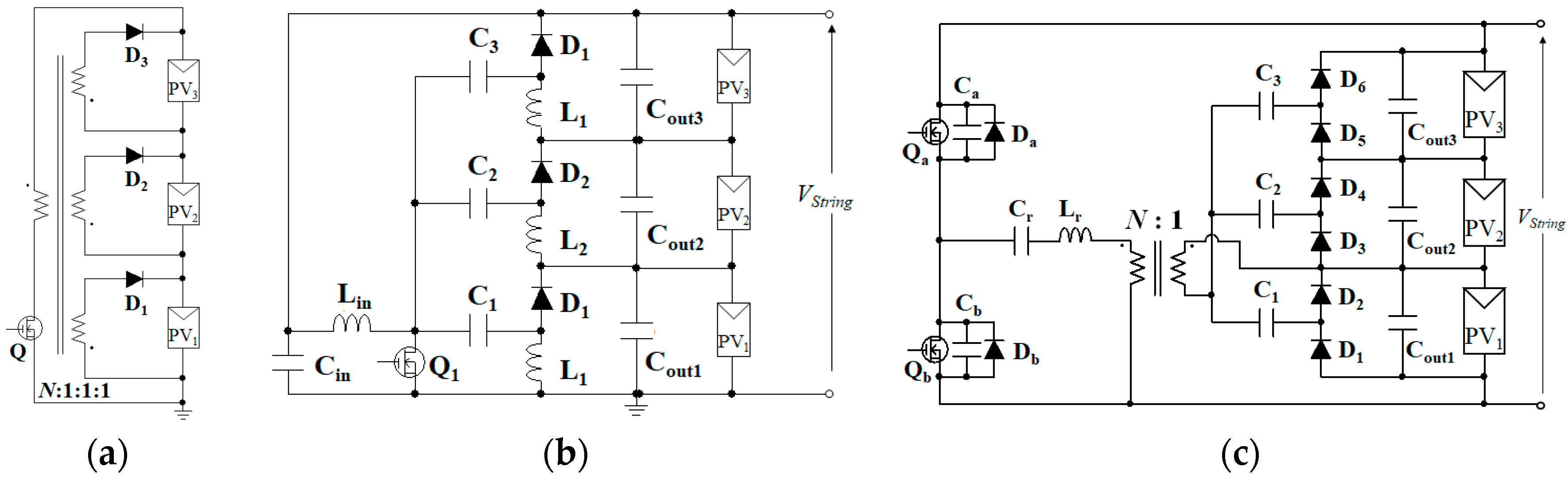
Figure 5.
String-to-module DPP converters: (a) multi-winding flyback converter [21], (b) multi-stacked buck-boost converter [22,23], (c) series resonant voltage multiplier [24].

Figure 6.
Integrated PWM converters: (a) Single-switch single-magnetic converter integrating resonant voltage multiplier (RVM), (b) Single-switch transformer-less converter, (c) Dickson-SCC converter, (d) Dickson-SCC tapped-inductor converter, (e) Ladder-SCC buck converter.
Figure 6.
Integrated PWM converters: (a) Single-switch single-magnetic converter integrating resonant voltage multiplier (RVM), (b) Single-switch transformer-less converter, (c) Dickson-SCC converter, (d) Dickson-SCC tapped-inductor converter, (e) Ladder-SCC buck converter.

Figure 7.
Voltage conversion ratios of five integrated PWM converters.

Figure 8.
Proposed single-switch single-magnetic PWM converter integrating non-resonant voltage multiplier (NRVM).
Figure 8.
Proposed single-switch single-magnetic PWM converter integrating non-resonant voltage multiplier (NRVM).

Figure 9.
Key operation waveforms when PV1 is partially shaded.

Figure 10.
Current flow paths in (a) Mode 1, (b) Mode 2, (c) Mode 3, and (d) Mode 4.

Figure 11.
Waveform comparison between NRVM and RVM.

Figure 12.
DC Equivalent circuit.

Figure 13.
30-W prototype.

Figure 14.
(a) Experimental and (b) dc equivalent circuit set up to measure output characteristic of NRVM.
Figure 14.
(a) Experimental and (b) dc equivalent circuit set up to measure output characteristic of NRVM.

Figure 15.
Measured and calculated output characteristic of NRVM.

Figure 16.
Measured key operation waveforms at Vload = 8.0 V and Iload = 2.8 A.

Figure 17.
Experimental results: (a) Individual module characteristics, (b) measured string characteristics with/without integrated PWM converter.
Figure 17.
Experimental results: (a) Individual module characteristics, (b) measured string characteristics with/without integrated PWM converter.

Figure 18.
DC equivalent circuit-based simulation results.


Table 1.
Quantitative comparison for integrated PWM converters.
| Topology | Switch Count | Magnetic Component Count | Voltage Conversion Ratio |
|---|---|---|---|
| Single-Switch Single-Magnetic | 1 | 1 | |
| Single-Switch Transformerless | 1 | 2 | |
| Dickson-SCC | 4 | 1 | |
| Dickson-SCC Tapped-Inductor | 4 | 1 | |
| Ladder-SCC | 4 | 1 |
Table 2.
Circuit parts used for the prototype.
| Component | Value |
|---|---|
| C1, C2 | Ceramic Capacitor, 30 μF, 16 V |
| Cin1, Cin2 | Ceramic Capacitor, 50 μF, 16 V |
| D1–D4 | Dual Schottky Barrier Diode, SBE813, Vf = 0.435 V |
| Q1, Q2 | Dual MOSFET, IRF7341, Ron = 50 mΩ |
| Cout | Ceramic Capacitor, 66 μF |
| Transformer | N1:N2 = 8:4, Lmg = 32 μH, Lkg = 0.94 μH EFD 30 Core (N87), 30-Strand Litz Wire with Diameter of 0.66 mm |
© 2019 by the authors. Licensee MDPI, Basel, Switzerland. This article is an open access article distributed under the terms and conditions of the Creative Commons Attribution (CC BY) license (http://creativecommons.org/licenses/by/4.0/).
Share and Cite
MDPI and ACS Style
Uno, M.; Shinohara, T.; Saito, Y.; Kukita, A. Review, Comparison, and Proposal for PWM Converters Integrating Differential Power Processing Converter for Small Exploration Rovers. Energies 2019, 12, 1919. https://doi.org/10.3390/en12101919
AMA Style
Uno M, Shinohara T, Saito Y, Kukita A. Review, Comparison, and Proposal for PWM Converters Integrating Differential Power Processing Converter for Small Exploration Rovers. Energies. 2019; 12(10):1919. https://doi.org/10.3390/en12101919
Chicago/Turabian StyleUno, Masatoshi, Toshiki Shinohara, Yota Saito, and Akio Kukita. 2019. "Review, Comparison, and Proposal for PWM Converters Integrating Differential Power Processing Converter for Small Exploration Rovers" Energies 12, no. 10: 1919. https://doi.org/10.3390/en12101919
Note that from the first issue of 2016, this journal uses article numbers instead of page numbers. See further details here.