Thermodynamic and Aerodynamic Analysis of an Air-Driven Fan System in Low-Cost High-Bypass-Ratio Turbofan Engine


College of Energy and Power Engineering, Nanjing University of Aeronautics and Astronautics, Nanjing 210016, China
*
Author to whom correspondence should be addressed.
Energies 2019, 12(10), 1917; https://doi.org/10.3390/en12101917
Submission received: 27 March 2019
/
Revised: 21 April 2019
/
Accepted: 16 May 2019
/
Published: 20 May 2019
Abstract
:In some cases, the improvement of the bypass ratio (BPR) of turbofans is pursued for military or civilian purposes owing to economic, environmental, and performance reasons, among others. However, high-BPR turbofans suffer from incompatibility of spool speed, complex structure for manufacture, development difficulty, and substantially increasing costs, especially for those with small batch production. To deal with the issues, a novel low-cost concept of high-BPR turbofan with air-driven fan (ADTF) is presented in this research. First, the problems faced by high-BPR turbofans are discussed, and the difficulties of geared turbofan (GTF), which is developed as a solution to the problems, are analyzed. A novel turbofan with potential advantages is proposed, and its basic theory is interpreted. Second, high-BPR ADTF is analyzed at the top level, and the design principle and important primary parameters are discussed. Some important concepts and criteria are proposed, enabling the comparison between ADTF and GTF. Finally, an air-driven fan system, the core part of ADTF, is exploratorily designed, and numerical simulation is performed to demonstrate its feasibility.
1. Introduction
Airbreathing propulsion systems, such as turbofan engines, are widely used for civilian and military purposes. Since the 1990s, aviation companies have been suffering from a serious operating cost problem due to high fuel prices. Also, the future of this industry is affected by the growing environmental concerns. Restricting noise, limiting engine exhaust gas emissions, and reducing toxic wastes challenge the industry with the increasingly stringent environmental regulations [1]. To protect the environment, the Advisory Council for Aeronautics Research in Europe has set specific goals in the aviation industry to be achieved by year 2020 [2]. The engine requirements toward these goals include 80% NOx emission reduction, 20% fuel consumption (and CO2 emissions) reduction per passenger-kilometer, and 10 dB noise reduction per certification point, with the data in the year 2000 as the basis of comparison [3]. Therefore, decreasing fuel consumption is of great interest [2]. Aspects of fuel economy, emissions, and noise continue to compel the aircraft industry to search for fuel-efficient, low noise, and pollutant-free aircraft engines [1]. Although further improving the efficiency of the parts of turbofan engines is difficult, increasing propulsive efficiency by increasing bypass ratio (BPR) (equivalent to reducing exhaust velocity) decreases specific fuel consumption [2], which also contributes to the reduction of emissions. In addition, the reduction of exhaust velocity lowers noise level. Apart from turbofans, open rotors, propfans, and unducted fan engines can also be used in improving fuel consumption as their propulsive efficiency is better than that of turbofan engines owing to their low exhaust velocities [4]. However, flight speed is the main limitation of these concepts. For a conventional propeller with straight blades, compressibility effects play a significant role and decreases propeller efficiency when the flight Mach number is above 0.6 [2]. Thus, this research focuses on turbofans to guarantee high-efficiency aircrafts at high subsonic flight speed. To summarize, the improvement of the BPR of turbofans may solve the main issues of fuel economy, emissions, and noise in the civil aviation industry.
With respect to military uses, different missions have different demands on airbreathing propulsion systems. In recent years, small/mid-size low-cost unmanned air vehicles (UAVs), cruising missiles, and small aircrafts have been proven to be of great importance [5,6]. In this study, airbreathing propulsion systems used for UAVs and missiles have something in common with civil engines. Other types of engines, such as low-BPR turbofan used in fighter engines, are not included here. Although UAVs have military or civilian purposes, such as combat, data gathering, surveillance missions [6], hurricane science, and communication relay [7], this study focuses only on their military uses. High performance, which means long endurance, long range, and high speed, is important for small UAVs, especially for military uses, entailing more requirements on their propulsion systems. High-BPR turbofan is a good option for propulsion systems because of its advantage of low fuel consumption and high speed. The improved performance of small turbofans must be within the constraints of manufacturing costs and engine operational durability [8]. Therefore, the increase in fuel economy is realized through improvement of aerothermodynamic components or thermodynamic parameters, such as BPR, and the increase of BPR really matters for the application of UAVs in military use (some kinds of missiles are similar) to further increase mission range and endurance.
Nevertheless, the improvement of the BPR of turbofans faces difficulties for civilian and military purposes. For civil turbofans, potential benefits, such as actual fuel saving, due to improvement of BPR are limited. Fan core speed incompatibility and low-cost contradiction rise as two major problems, which will be discussed in detail in the following passage. Due to the incompatibility of spool speed, the conventional turbofan design becomes unfavorable for BPR well above 10 [9]. To solve this problem, geared turbofan (GTF) configuration has been accepted as a promising candidate for the future engines with BPR above 10 [10]. Introducing a reduction gear between the fan and LPC/LPT system enables each low-pressure (LP) component to rotate at its optimum speed in terms of efficiency, stage loading, and noise [3]. However, the introduction of the gearbox also brings complicated structures and so-called low-cost contradiction. Thus, the optimal design of civil turbofans with high BPR is a tradeoff among specific fuel consumption, complexity, and cost. Similar problems also exist in turbofans for military purposes, such as for small UAVs. In designing turbofans for this purpose, several main aspects, such as performance (including range, endurance, and speed), reliability, and cost (including manufacturing cost, development costs, maintenance cost, and fuel consumption), are considered and balanced [11]. So, fan core speed incompatibility and low-cost contradiction must also be settled in some cases for military purposes.
Thus, the main issues of fan core speed incompatibility and low-cost contradiction concerning the improvement of BPR of turbofans are discussed in detail below.
1.1 Fan Core Speed Incompatibility Problem
Given a significant increase in BPR, the turbofan must reduce its spool speed to maintain its fan tip speed as the radius increases for the same engine core. This, in turn, increases the number of stages for the LPC and LPT to maintain appropriate efficiencies and pressure ratios for these parts. In addition, reduced LP spool speed requires high torque of the LP shaft, and this will lead to big shaft diameters and increased core size. Furthermore, in order to run a bigger diameter fan, LP turbine diameter and its number of stages must increase [1,2,8,9]. In conclusion, the fan of high-BPR turbofans prefers low spool speed, but the LP turbine driving the fan prefers high spool speed. This contradiction is hard to solve, and we need a compromise to harmonize these two factors.
Three-rotor scheme and GTF aim to solve the incompatibility problem. In this section, GTF is taken as an example to show collateral shortcomings and difficulties when solving the incompatibility problem to some extent. To solve the fan core speed incompatibility problem, a reduction gear system is introduced in GTF, to decouple the fan from the rest of the LP system (as illustrated in Figure 1a). As a result, the fan and LP system can operate at their preferred optimum speeds. With regards to the relief of the incompatibility problem, the advantages of GTF, such as high component efficiencies of LPT, intermediate pressure compressor and LPC, low fan tip speed that also results in low fan noises, and low diameter with less stages of LPT, are apparent when BPR is high [1]. All disadvantages of GTF are involved with the introduction of gearbox and gearbox efficiency, including a more complex structure with an attachment system, such as fuel cooling capacity, development and manufacture difficulty, reliability, and durability problem, as BPR further increases [1].
1.2. Low-Cost Contradiction
A bottleneck exists, whereby the so-called incompatibility of spool speed limits the increase of BPR. Solutions to this problem, such as the three-rotor scheme and GTF, result in increased structural complexity and development and manufacture cost, especially for some cost-sensitive or small-batch production situations, such as military and scientific uses. For example, shafting structures, bearing, and lubrication systems are complex in the three-rotor scheme. Furthermore, development is extremely difficult because only Rolls Royce can manufacture RB211, and the three-rotor scheme suffers from high maintenance cost. Moreover, the great difficulty of GTF lies in the design and manufacture of high-power gear box. Pratt and Whitney took nearly a decade to develop the first GTF, PW8000G [12], which is based on a prototype PW8000. Thus, under comprehensive consideration, the performance and cost of high-BPR turbofans contradict each other, and fine balance routinely contributes to the optimum choice of BPR.
1.3. Thinking of A Solution
While thinking about other ways to solve the fan core speed incompatibility and low-cost contradiction, we first noticed that whatever the specific structure is, turbofans share the same principle; that is, the higher the bypass mass flow rate to which the core transfers energy, the less specific fuel consumption (SFC) and high performance the turbofans have. GTF solves the fan core speed incompatibility problem. The gearbox has two functions, reducing the spool speed and transferring energy from LP turbine to fan. Thus, solutions that satisfy the two functions are also promising. However, the turbofan theory does not restrict the means of transferring energy. Any method that can transfer energy from core to bypass, if consistent with the physical theories and reduce the fan speed, may be used for high-BPR turbofan. This concept should use mature techniques and should not introduce many complex structures to limit the cost and relieve the low-cost contradiction. For example, tip turbine is used to solve this problem in some cases [13,14].
Thus, to solve the two main issues, a novel concept of high-BPR turbofan with air-driven fan (ADTF) is proposed to increase BPR. In this concept, energy is transferred in an aerodynamic way rather than mechanical way (such as in GTF). Compared with the three-rotor scheme and GTF, this concept has simpler structures and may be promising to overcome the difficulties and uncertainty, balancing the contradiction between performance and cost.
2. Concept of High-BPR ADTF
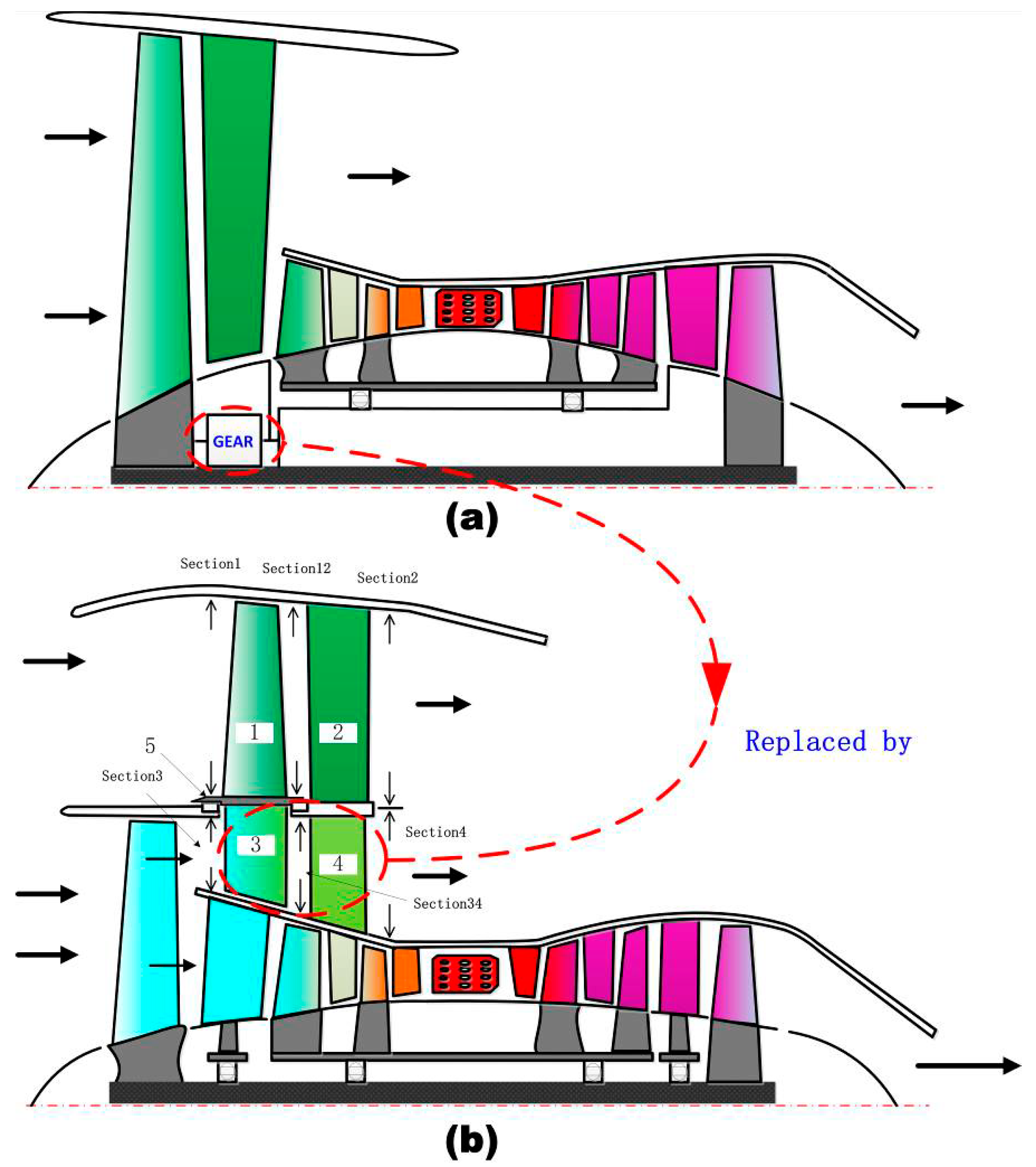
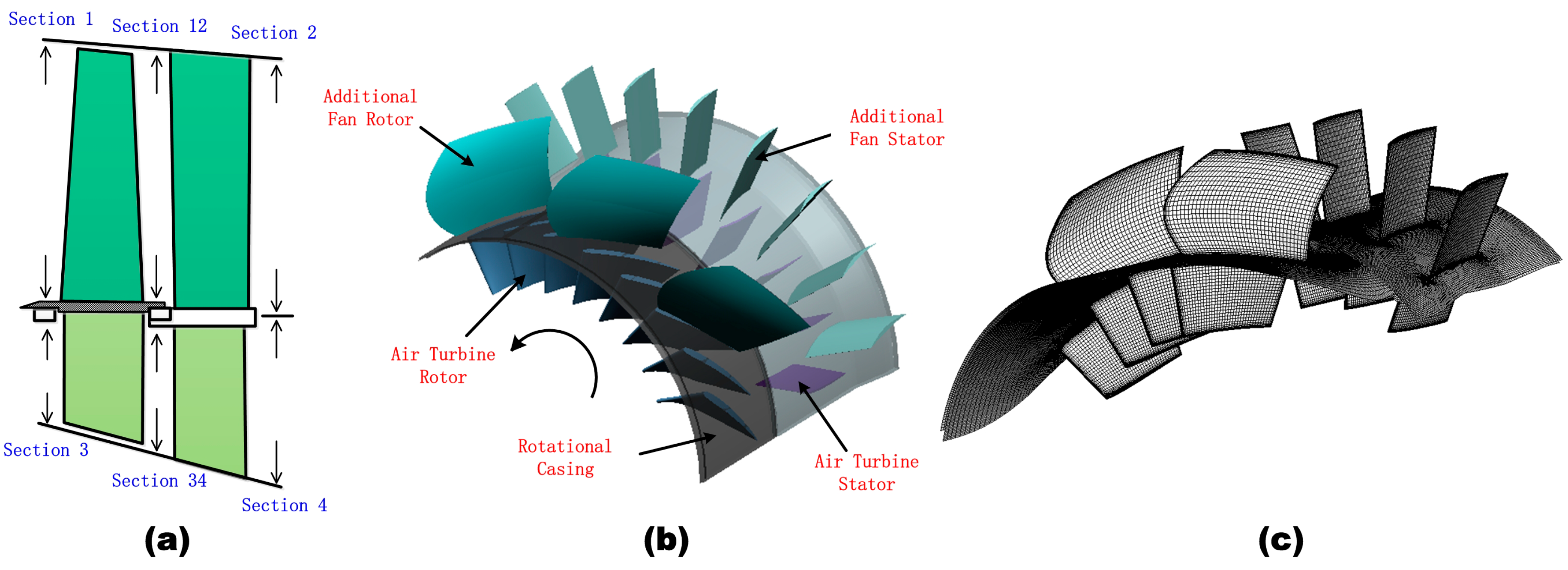
In this section, a novel concept of high-BPR ADTF is introduced. For a traditional two-spool turbofan, the fan is directly driven by LPT. In addition to the traditional two-spool turbofan, GTF adds a reduction gear box to transfer energy from the core while reducing the LP spool speed, as illustrated in Figure 1a. The new turbofan concept we propose is also derived from a traditional two-spool turbofan, but the gear box is replaced by an air turbine, which is surrounded by red dashed lines as illustrated in Figure 1b. The new concept is named air-driven turbofan or ADTF.
ADTF has five important components, namely, additional fan rotor (1), additional fan stator (2), air turbine rotor (3), air turbine stator (4), and rotational casing (5), as shown in Figure 1b. Other parts in Figure 1b share the same parts of the traditional two-spool turbofan or GTF shown in Figure 1a. Therefore, ADTF can be easily developed from a prototype traditional two-spool turbofan and save much design cost. Such design has already been authorized as a Chinese invention patent [15].
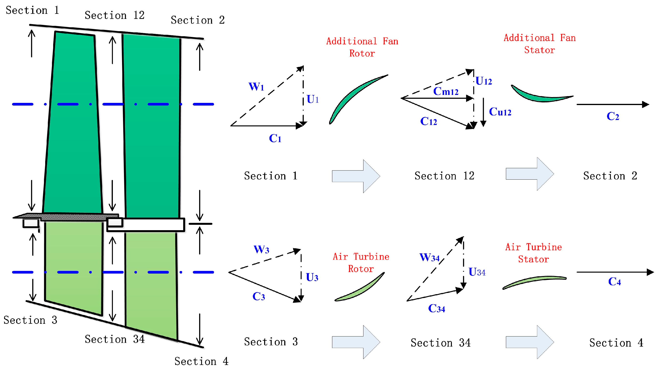
To further interpret the basic theory of air-driven fan system, the velocity triangles of the fan and air turbine are shown in Figure 2. The outer flow path includes additional fan rotor and its stator. At Section 1, the air from the atmosphere only has axial velocity C1. Meanwhile, its relative velocity is W1 in the relative coordinate system of additional fan. After flowing through the additional fan rotor, the air is pressurized with its circumferential velocity increases from 0 to Cu12. The stator before Section 2 changes the absolute velocity of the air from C12 to C2 and the static pressure increases. Moreover, the inner flow passes by air turbine rotor and its stator. Air turbine is the main part that extracts energy from moderate pressure air. A natural and traditional idea is to introduce a prototype fan stator to transfer circumferential velocity into static pressure and an air turbine stator to accelerate the flow and produce circumferential velocity for the air turbine rotor. Inspired by a patent [16], this idea is replaced by a currently better scheme in which the air turbine stator is installed downstream from the air turbine rotor. As a result, the part of the prototype fan stator can be saved, and complexity and weight can be reduced. At Section 3, the air has circumferential velocity components. The air turbine rotor decelerates the circumferential velocity while extracting energy. The air turbine stator is aimed to eliminate possible circumferential velocity. Meanwhile, in some cases, its circumferential velocity component is so small that the air turbine stator can be cancelled or just replaced as a support plate.
A new concept of high-BPR ADTF and its theory are outlined in this section. To design a high-BPR ADTF with better performance and understand the advantages and disadvantages of ADTF, conceptual and thermodynamic analysis of high-BPR ADTF is presented in the next section.
3. Thermodynamic Analysis of High-BPR ADTF
After the proposal of high-BPR ADTF, we must know the design criteria that direct us to design a well-performing ADTF and inform us how design parameters affect one another. For convenience of analysis and comparison, some special parameters, such as efficiency of equivalent aerodynamic reduction gear box (EARGB) and effective BPR, are defined and discussed using the equivalent method. At the end of this part, armed with the design criteria and theoretical analysis, thermodynamic analysis is performed to evaluate the effects that different main parameters have on the performance of ADTF based on a prototype turbofan. A rough comparison between ADTF and GTF is then made, further showing the characteristics and application scope of ADTF.
3.1 Criteria for Design Parameters
For a prototype turbofan that will be adapted to an ADTF, three main design parameters are known, namely, mass flow rate in the bypass of prototype fan , total pressure ratio of prototype fan , and total temperature at the outlet of prototype fan . The air-driven fan system (including the additional fan and air turbine) has four main overall design parameters: Mass flow rate of additional fan , total pressure ratio of additional fan , mass flow rate of air turbine , and total pressure drop ratio of air turbine . Figure 1b shows that . Thus, only three design parameters must be determined. Now, we discuss the constraints for these design parameters.
(1) Power balance relation
Power balance means that the power that air turbine produce equals to that needed by the additional fan. Therefore,
where is the ambient total temperature, is the isentropic efficiency of additional fan, is the isentropic efficiency of air turbine, is isobaric specific heat capacity of air, and k is ratio of specific heats of air.
(2) Thrust condition
The thrust produced by the air-driven fan system is determined by its application scenario. Figure 1b shows that the thrust of air-driven fan system consists of two parts, one produced by the additional fan and the other produced by the air turbine. According to the formula of nozzle thrust:
where is the required thrust of the air-driven fan system, is total temperature at the outlet of air turbine, and is total temperature at the outlet of additional fan. According to the formula for power of turbomachinery, we deduce that
We combine Equations (2) and (3) to obtain the following thrust condition:
(3) Total pressure relation
To design a high-performance high-BPR turbofan, potential losses must be minimized. For the newly proposed concept of high-BPR ADTF, some apparent aerodynamic losses can be easily reduced due to fine primary parameter design, but not until the stage of detailed aerodynamic design. When the flow exits the air turbine, it will mix with the bypass flow, thereby resulting in the loss of mixture. To avoid this flow loss as much as possible, the total pressure at the outlet of air turbine must be the same (or nearly the same) as that at the outlet of the additional fan, which is the total pressure relation shown as
In summary, three main independent design parameters , , and satisfy the relations described by Equations (1), (4), and (5). These design parameters are then determined because the number of unknown parameters is equal to that of the equations.
3.2. Theoretical Analysis
ADTF is an entirely new concept, which changes the thermodynamic cycle of the prototype turbofan and lacks mature primary parameters analysis method and model in commercial gas turbine performance simulation software. To quickly determine the parameter sensitivity of ADTF, the equivalent method is used, treating ADTF as a variant of GTF. Two new and unique parameters are then proposed to realize this equivalence. The efficiency of EARGB in ADTF is equivalent to the efficiency of a reduction gear box in GTF, whereas effective BPR in ADTF is equivalent to BPR in GTF. The two parameters are proposed and deduced in the following passage, and primary parameters are then analyzed using commercial gas turbine performance simulation software GasTurb [17].
(1) Analysis of power transfer efficiency
In order to improve propulsion efficiency, turbofans do their best to transfer the available energy from core to bypass. When core engines of turbofans are the same, SFC is only dependent on BPR and power transfer efficiency, which is an important index that reflects how well the energy is transferred from core to bypass. For a normal turbofan or GTF, power transfer efficiency can be expressed simply as multipliers:
where is the power transfer efficiency (from core to bypass), is the mechanical efficiency, is the gear box efficiency, is the power transfer efficiency of the prototype fan, and is the power transfer efficiency of bypass duct. Usually, . The function of pressure ratio is defined as
Then, the relation between and is
Thus, only when or . Moreover, the relation between and commonly used (total pressure recovery coefficient of bypass duct) is:
For ADTF, the air-driven fan system uses a part of the available energy from the core turbofan, so the thermodynamic cycle parameters of the equivalent turbofan are changed. Imitating Equation (6), the power transfer efficiency of the equivalent turbofan can be expressed as
where refers to the efficiency due to the added parts, such as air turbine and additional fan of ADTF, which only depend on the design level of turbomachine; and corresponds to in form, so it is named the efficiency of EARGB.
(2) Efficiency of EARGB and effective BPR
For ADTF, through energy transfer analysis, we know that
where is the power transfer efficiency of the additional fan. According to Equations (1), (3), (5), and (7), we can deduce that
According to this equation, when and , no loss occurs in the power transfer process; when and , the loss in the power transfer process only comes from the fan of main engine. Moreover, the range of is determined as
This air-driven fan system can change the BPR of the prototype turbofan. If the BPR of the prototype turbofan is , then its mass flow at the inner duct is . According to Equation (1), the effective BPR of ADTF is shown as
The effective BPR of ADTF is larger than the prototype BPR, and the air-driven fan system serves as a kind of BPR “amplifier.” With both parameters of efficiency of EARGB and effective BPR, primary performance parameters can be easily analyzed via the existing mature overall performance analysis method.
3.3. Thermodynamic Analysis of High-BPR ADTF
To thermodynamically analyze the main parameters of ADTF, a prototype turbofan model is used (see Reference [18] and Table 1 fore the main parameters).
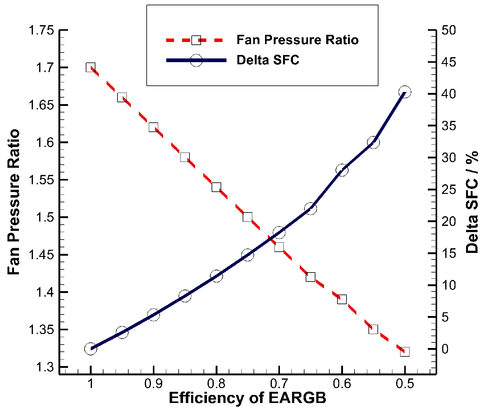
The influence of efficiency of EARGB on fan pressure and SFC is shown in Figure 3. When other main parameters remain the same, as efficiency of EARGB drops, the energy delivered from LPT to fan goes down, decreasing fan pressure ratio. The decrease of fan pressure ratio also increases SFC. For example, when efficiency of EARGB is approximately 0.9, SFC increases by approximately 5%, which means that the economy of ADTF is acceptable. Equation (13) shows that the efficiency of EARGB has a low limit. When , the minimum of is approximately 0.82, and SFC drops by approximately 10%. This finding means that under the condition of high efficiency of the aerodynamic parts, the economy of ADTF is acceptable even in the extreme case.
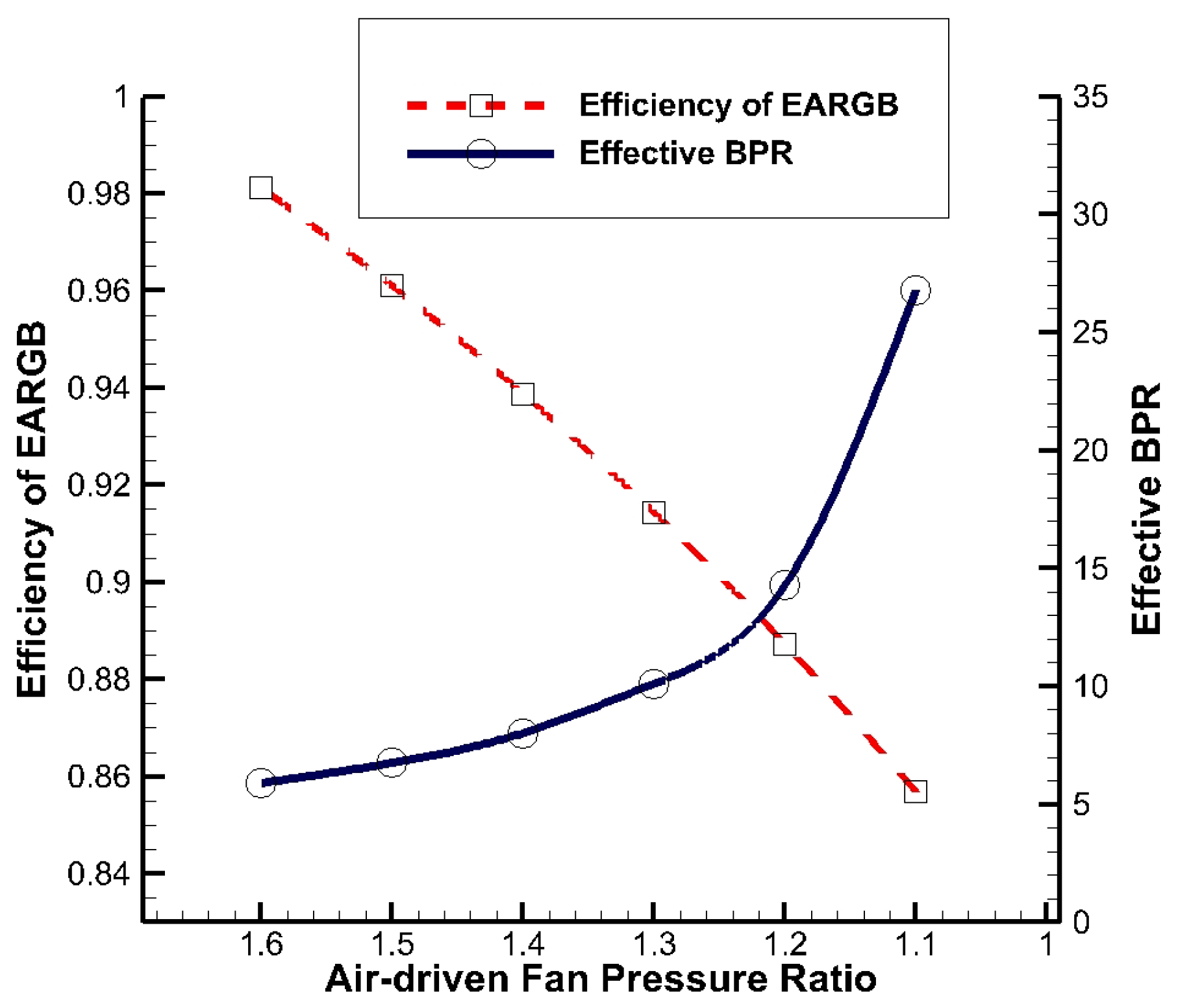
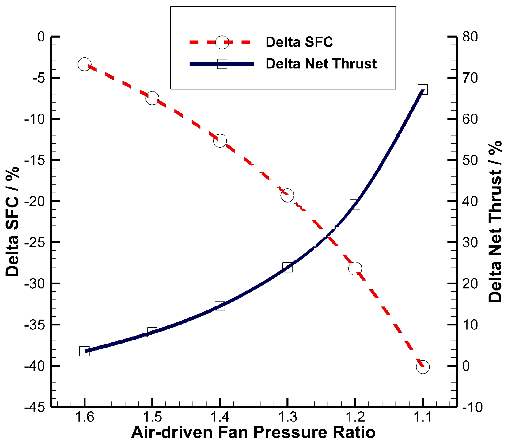
Given that , , and remain constant and are equal to 0.9 (around the current design level in reality), the efficiency of EARGB and effective BPR only depend on the prototype fan pressure ratio and additional fan pressure ratio based on Equations (12) and (14). If ADTF is based on an existing, mature turbofan, as shown in Table 1, then the prototype fan pressure ratio is fixed, and only the additional fan pressure ratio is a variable. As additional fan pressure decreases from 1.6 to 1.1, the efficiency of EARGB drops from 0.98 to 0.86 and effective BPR increases from 6 to 27 because the pressure-drop ratio of the air turbine and the mass flow rate of air the additional fan drives increase (See Figure 4). In addition, Figure 5 shows that as additional fan pressure decreases from 1.6 to 1.1, SFC drops from 3% to 40%, whereas net thrust increases from 3% to 67%, mainly due to the influence of efficiency of EARGB and effective BPR.
Figure 3, Figure 4 and Figure 5 show an apparent dilemma. When designing an ADTF, choosing low additional fan pressure means low SFC and high net thrust, and it also means low efficiency of EARGB, which creates high SFC increase. However, choosing high additional fan pressure means that the effective BPR, SFC, and net thrust cannot be notably changed. Therefore, proper additional fan pressure must be chosen to remarkably reduce SFC and limit the counteraction of SFC due to low efficiency of EARGB. An additional fan pressure of 1.2 is proper in this case, whereas the effective BPR is approximately 14.
3.4. Brief Comparison between ADTF and GTF
The concept of EARGB has already been discussed, and its efficiency can be calculated according to Equation (12). For example, based on the prototype turbofan described in Table 1, a proper set of parameters, = 1.2, = 1.7, and = = = 0.9, makes = 0.89. Compared with ≈ 0.99 in GTF, the energy transfer efficiency of ADTF is slightly low because ≈ 0.9, and SFC increases by approximately 5%, as shown in Figure 3. However, ADTF can greatly increase BPR, even making it larger than 12, and this is still difficult for GTF. To conclude, ADTF applies to very-high-BPR (more than 12) turbofan well, dodging the proper BPR range of GTF.
Apart from the slightly low energy transfer efficiency, ADTF has more advantages in structure complexity, development difficulty, and manufacture difficulty, dealing better with the fan core speed incompatibility problem and low-cost contradiction. The SFC of ADTF is slightly higher than GTF at the same BPR. However, less development and manufacture difficulty makes ADTF more suitable for cost-sensitive and small-batch situations, such as regional jets and small UAVs. The comparison between ADTF and GTF is shown in Table 2.
4. Exploratory Design and Aerodynamic Analysis of an Air-Driven Fan System
4.1 Exploratory Design of An Air-Driven Fan System on the Basis of a Prototype Turbofan
To demonstrate the feasibility of the ADTF concept, the case of air-driven fan system, which is the most innovative and doubtful section, is exploratorily designed on the basis of a prototype turbofan shown in Table 1. Design targets are determined from the thermodynamic analysis. The appropriate total pressure ratio of the additional fan is selected as 1.2, and the mass flow rate of air turbine is equal to that of the fan in the prototype turbofan (see Section 3.3), as shown in Table 3.
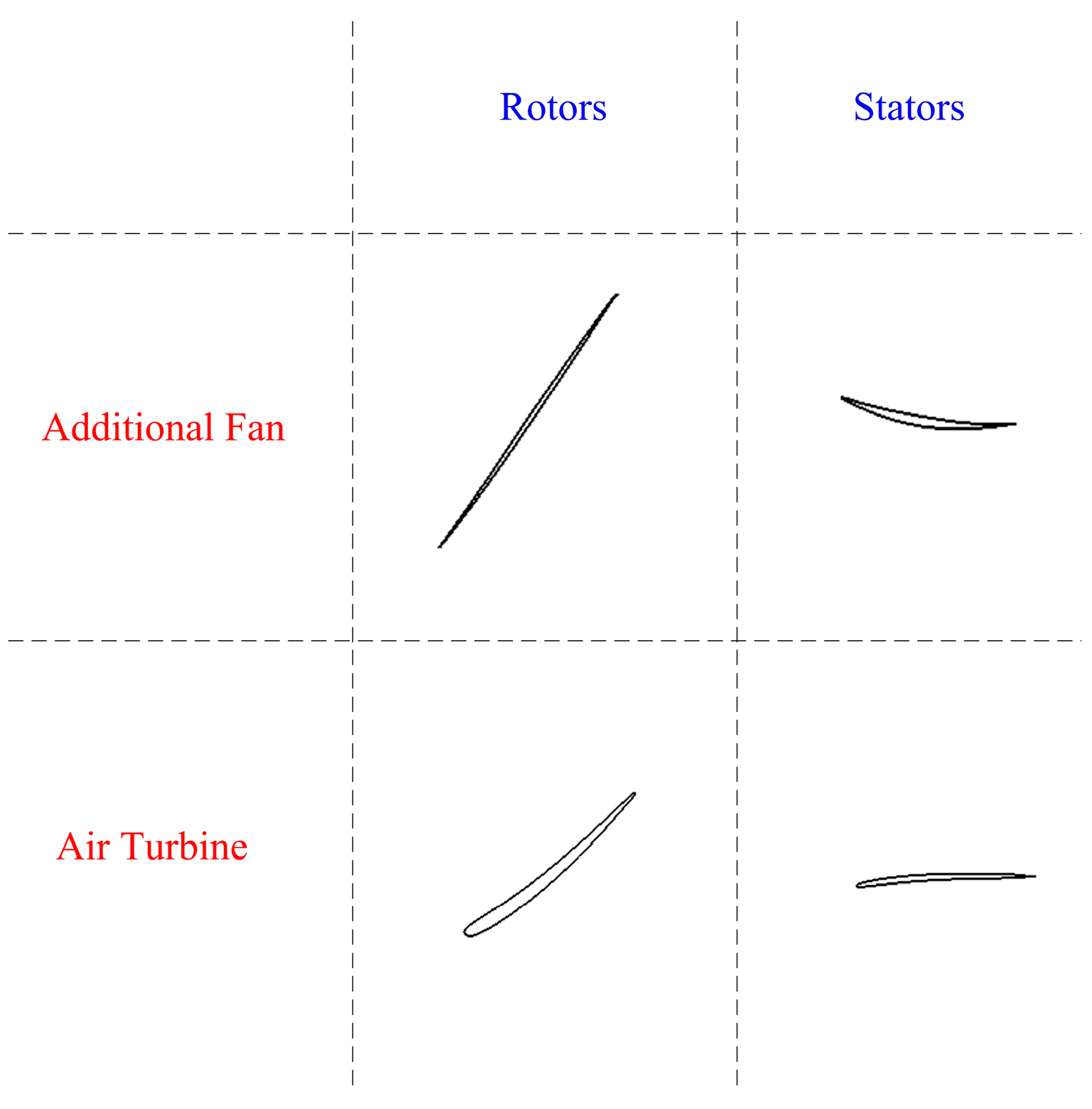
The design process of the air-driven fan system (shown in Figure 6a) is the same as that of other turbomachineries. The process follows a preliminary design, throughflow design (design on S2 surface), 2D blading design (design on S1 surface), and 3D blading design [19,20]. During the throughflow design process, the rotational speed of the air-driven fan system is set as 5000 rpm at its design point. On the basis of the throughflow design, the 2D blade profiles of the fan and the air turbine at 0%, 50%, and 100% spans are designed. The blade profiles of the additional fan and the air turbine at the 50% span are shown in Figure 7. Furthermore, the 3D blades are obtained by linear interpolation of these three sections. This process is completed by the aerodynamic design program of our group. The camber lines of the 2D blade profiles are made of multi-segment arcs. Also, taking the angles of attack and derivation into consideration, the blade angles are determined by iterations of numerical simulation. Cubic polynomial distribution of blade profile thickness is used, given the radius of leading and trailing edges, the maximum thickness, and its position. For the additional fan, the relative Mach number at its rotor tip is in a high subsonic state, so the position of maximum curvature and thickness must be shifted backward appropriately to avoid a strong shock wave.
Due to low pressure ratio in these parts, blade number and chord length greatly affect the performance of these parts, so the parameters are optimized in the design process. The selection of the blade number should ensure that the solidity of blades is within a reasonable range. In this paper, for the additional fan, the number of rotor blades is 10 and the stator is 21; while for the air turbine, the number of turbine blades is 23 and the stator is 17. Centroid stacking is used mostly for the blades. However, the fan rotor sweeps forward in the middle and sweeps backward at the tip to weaken the shock wave in the passage. In the end, 3D geometry of the additional fan and the air turbine is obtained by iteration design based on numerical simulation.
After the four design phases, an entire air-driven fan system, including the additional fan rotor, additional fan stator, air turbine rotor, and air turbine stator, is established and 3D modeled, as illustrated in Figure 6b.
4.2. CFD-Based Aerodynamic Analysis of the Air-Driven Fan System
To evaluate the aerodynamic design of the air-driven fan system, a CFD simulation is employed here. NUMECA packages are used for the simulation. For both rotors and stators, a single blade passage is taken as the calculation domain and Autogrid is used to generate the structured grid. An O-type mesh is used around the blade while a butterfly-type mesh (an H-type mesh surrounded by an O-type mesh) in the rotor clearance region. The total number of grid nodes is 2.2 × 10⁶, in which 1.0 × 10⁶ for the fan domain and 1.2 × 10⁶ for the air turbine. The entire mesh of the air-driven fan system is illustrated in Figure 6c.
Moreover, Fine/Turbo is used to simulate the flow field of the whole air-driven fan system. The boundary conditions are set as follows: Total pressure of the fan inlet is 101,325 Pa, total temperature of the fan inlet is 288 K, and static pressure of the outlet is given; total pressure of the air turbine inlet is 17,250 Pa, total temperature of the air turbine inlet is 341 K, and static pressure of outlet is given; adiabatic and non-slip boundaries are set for solid walls; rotating boundaries are adopted for rotors and their hubs while stationary boundaries for stators, their hubs, and casings; periodical boundaries are used on both circumferential sides of the blade passages; and the conservative coupling by pitchwise row is used for the rotor–stator interfaces. Also, the turbulence model used in this paper is Spalart-Allmaras (S-A) model. The solver Euranus is used to solve the steady N-S equation, and the convergence is accelerated by the multigrid technique.
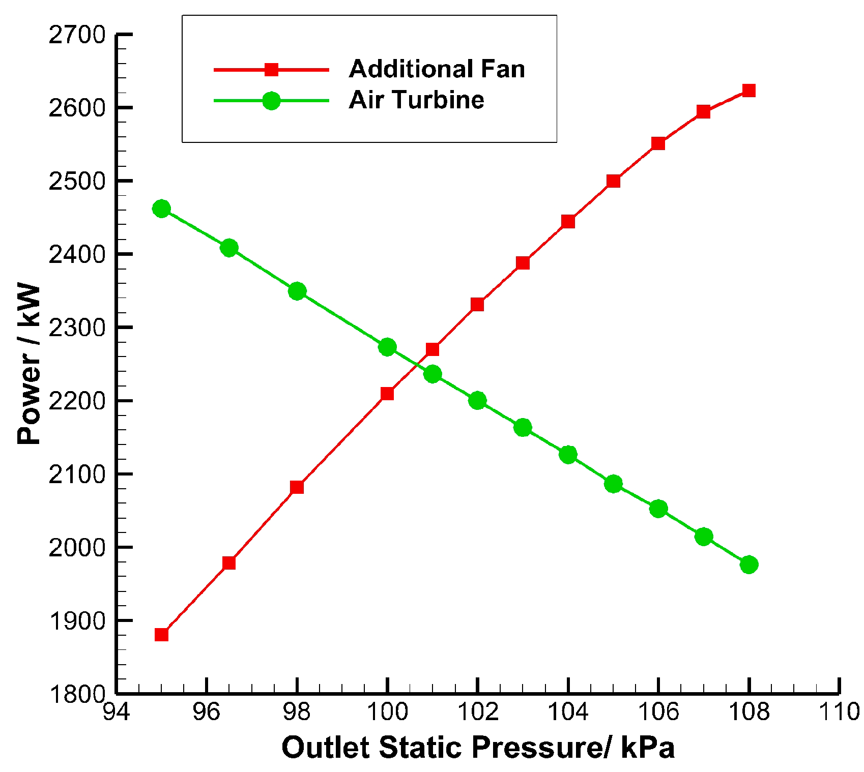
The characteristics of the air-driven fan system at the design speed are studied by CFD. The common working point is obtained according to the power balance relation. As illustrated in Figure 8, as the outlet static pressure (back pressure) increases, the power produced by the air turbine drops, while that needed by the additional fan increases. When the outlet static pressure is about 101 kPa (around the standard atmospheric pressure), power balance is achieved and the design point at the design speed is obtained. The CFD results at the design point are shown in Table 3. At the design point, the total pressure ratio, mass flow rate, and isentropic efficiency of the additional fan are 1.2, 126.7 kg/s, and 85.6%, respectively, and the total pressure drop ratio, mass flow rate, and isentropic efficiency of the air turbine are 1.40, 80.2 kg/s, and 89.6%, respectively. Compared with the design targets, the differences between the design targets and the simulation results are within permission because it is an exploratory design at this stage.
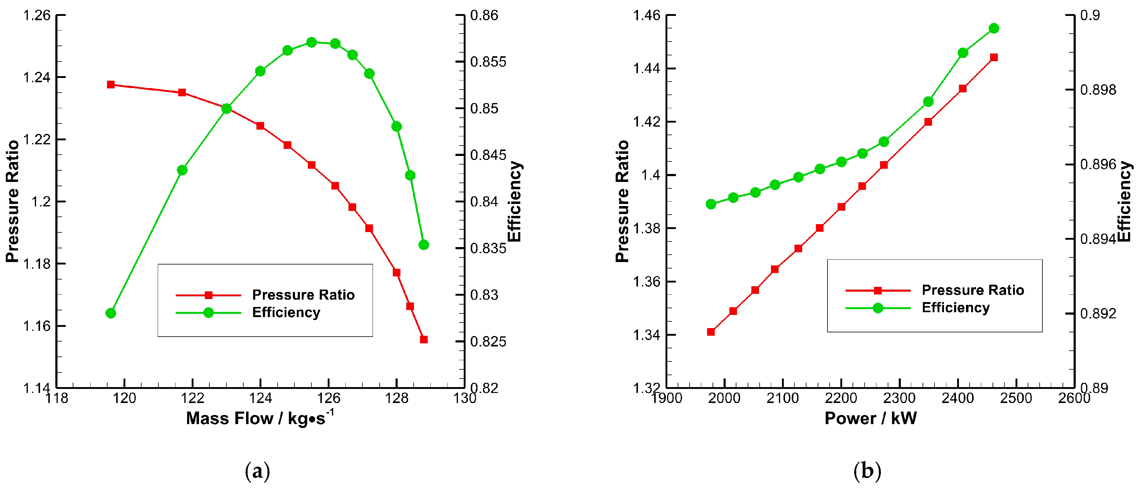
The characteristic lines of the additional fan and the air turbine at their design speed are shown in Figure 9. According to Figure 9a, the additional fan at the design point works near its maximum efficiency point. Due to the fact that the mass flow rate of the air turbine under the conditions we are concerned with remains at 80.2 kg/s, the power instead of mass flow rate is used as the abscissa in the characteristic map of the air turbine, as illustrated in Figure 9b. From this figure, it can be seen that the efficiency of the air turbine has little change (keeps around 0.9) within the scope of our concern; this highly efficient air turbine guarantees the energy transfer with less losses according to Equation (12).
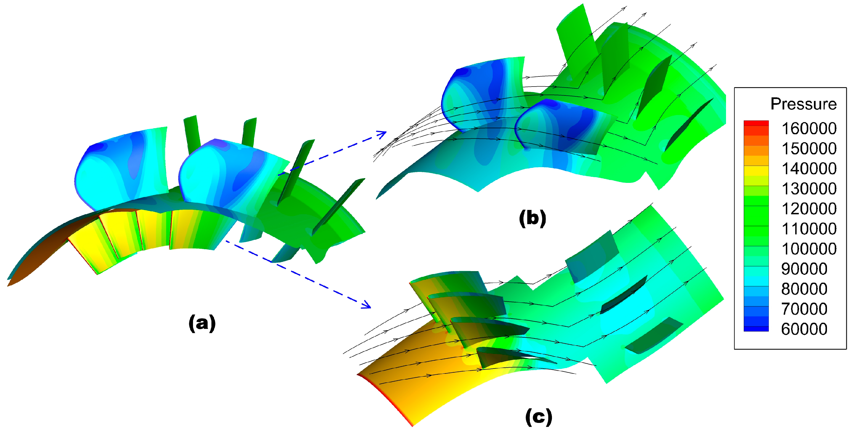
The overall flow feature of the air-driven fan system at the design point is shown in Figure 10a. Also, Figure 10b,c show the flow field in the additional fan and air turbine. The additional fan stator is employed to make the flow direction axial, whereas the air turbine stator is more like a support plate because small flow turning is required in this design. Under the circumstances with higher effective BPR, additional fan rotor will function like a ducted propeller, so circumferential velocity at the outlet can be ignored, which implies the absence of the need to introduce a stator (a tradeoff between structural complexity and propulsion efficiency). In these situations, additional fan stator and air turbine stator can be replaced by a small number of support plates to reduce weight.
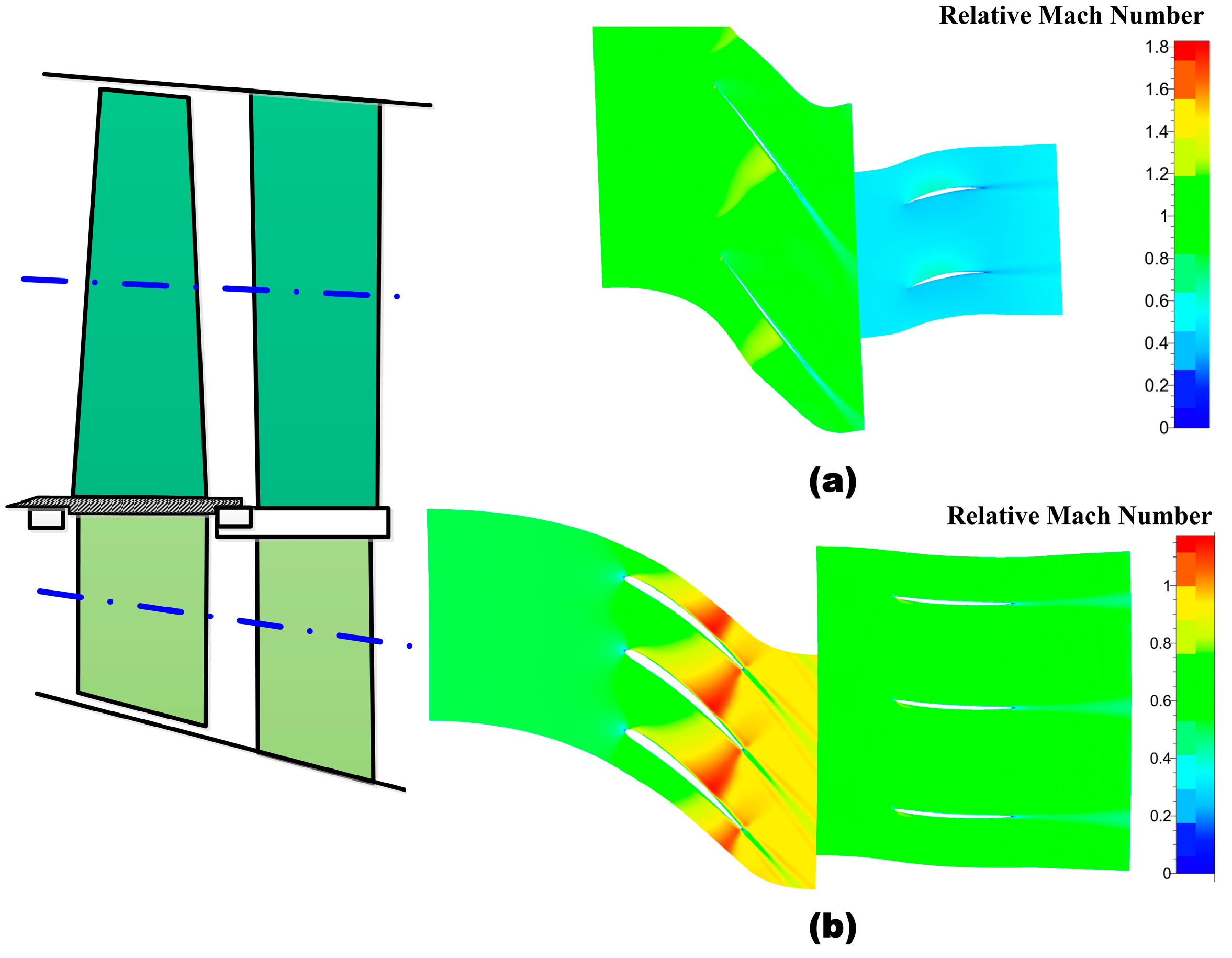
Figure 11a shows a relative Mach number contour of the additional fan at 50% span. It is indicated by this figure that the flow is supersonic at the inlet. There exists a shock wave that increases the pressure over pressure side, along with the expansion waves which decrease that over the suction side. These two kinds of waves both make a contribution to the aerodynamic load of the fan. In order to reduce the loss of shock wave, pre-shock wave Mach number is restricted below 1.2 during the design. Moreover, the relative Mach number contour of the air turbine at 50% span is illustrated in Figure 11b. According to this figure, the relative Mach number rises over 1.1 at the outlet of the stator, and a shock wave exists near the trailing edge. Although the existence of the shock wave brings more flow losses, the efficiency of turbine remains high because of the low pre-shock wave Mach number.
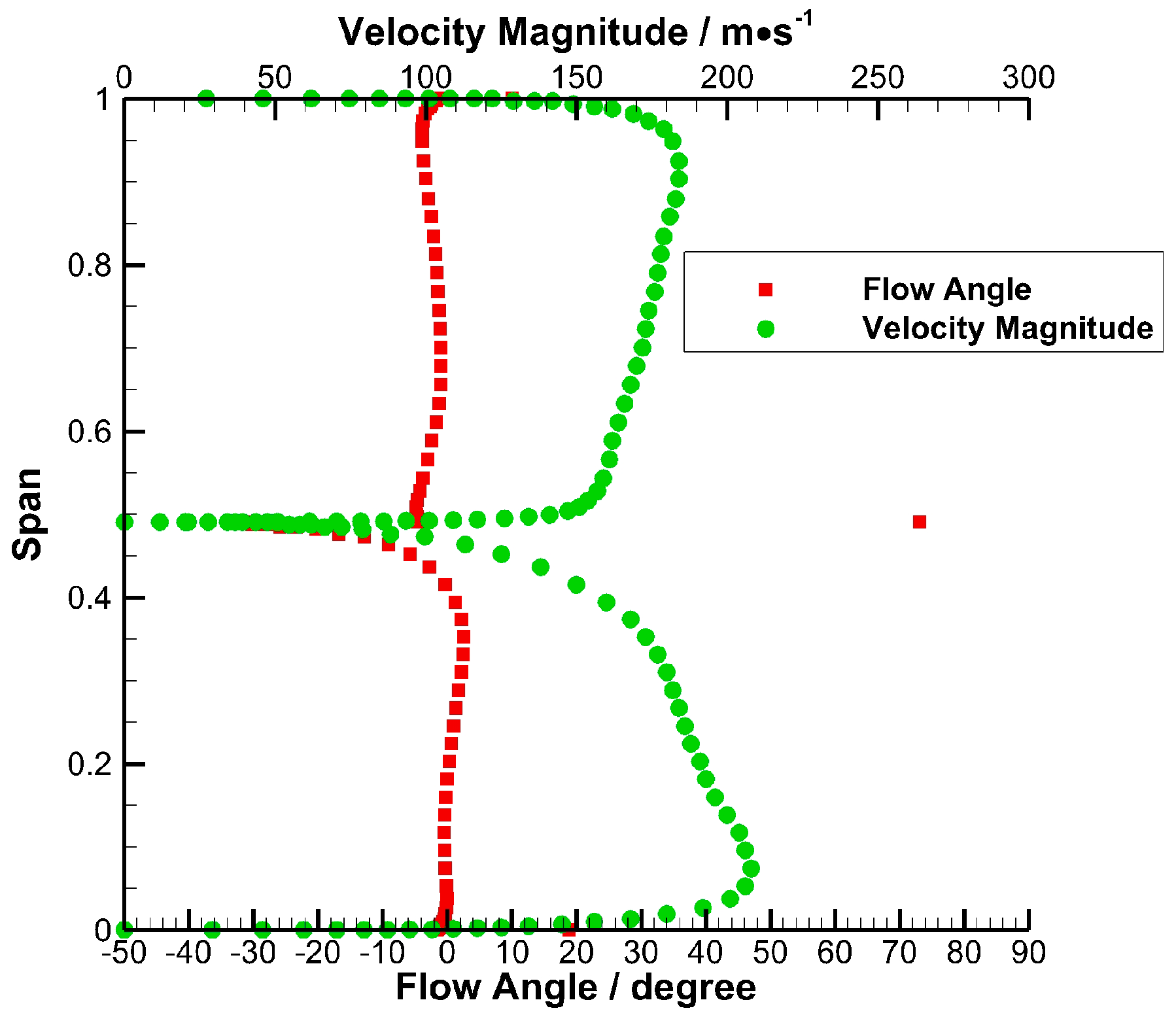
Another important issue is the flow mixing at the outlet (after the stators) of the additional fan and the air turbine. Figure 12 shows the spanwise distribution of circumferential-averaged flow angle and velocity magnitude at the outlet of the air-driven fan system. In this figure, the air turbine locates between 0% to 50% span while the additional fan between 50% to 100% span. According this figure, the flow angle is approximately zero at most of the span, which means the flow is roughly axial with the help of the stators (kinetic energy loss is reduced). Also, the velocity magnitude is between 150 m/s to 200 m/s at most of the span. So, the flow mixing mainly happens after the casing and the mainstream radial flow mixing is not the leading cause of loss.
In conclusion, the numerical results show that the design of the air-driven fan system satisfies the design targets. Therefore, the feasibility of the core part of ADTF, that is, the air-driven fan system, is demonstrated by the numerical simulation to a certain degree.
4.3. Comparison of Performance between the Prototype Turbofan and Demo ADTF
Given the CFD results of the air-driven fan system, the comparison of performance between the prototype turbofan and demo ADTF can then be made to exhibit the performance advantages of ADTF. According to Equation (12), the isentropic efficiency of the prototype fan rotor is 0.9, and the efficiency of EARGB () is 0.90. This result means that the increase of SFC due to the air-driven system, approximately 5%, is acceptable. Table 4 shows that when the air-driven fan system is added to the prototype turbofan, BPR can be improved by 156.6%, SFC can be reduced by 27.6%, and thrust can be improved by 38.4%. Therefore, the air-driven fan system, which serves as the so-called BPR “amplifier,” is able to greatly improve the high-BPR turbofan performance. Also, as shown in Table 4, the demo GTF (the same BPR with the demo ADTF) with the gearbox efficiency of 99% will reduce the SFC by 5.7% compared with the demo ADTF, verifying the analysis in Section 3.3 that the air-driven system will increase the SFC by 5% approximately.
Therefore, after the overall thermodynamic analysis and detailed aerodynamic design, ADTF is proven as a feasible method to improve the performance of a high-BPR turbofan, better dealing with the fan core speed incompatibility problem and low-cost contradiction, especially in cost-sensitive and small batch situations, such as regional jets and small UAVs. Further work remains to be done to improve the theory and practice of ADTF.
5. Conclusions
This research presents the thermodynamic and aerodynamic analysis of an air-driven fan for high-BPR turbofan engines. According to the above work, we can make the following conclusions:
- (1)
- A novel concept of ADTF is proposed in this research. ADTF can solve fan core speed incompatibility problem and relieve low-cost contradiction, serving as a promising candidate for high-BPR turbofan, especially for cost-sensitive and small batch applications, such as regional jets and small UAVs.
- (2)
- The design criteria of ADTF, namely, power balance relation, thrust condition, and total pressure relation, are proposed. To easily thermodynamically analyze ADTF and compare ADTF and GTF, the theoretical expression of the efficiency of EARGB and effective BPR are proposed using the equivalent method.
- (3)
- The parameter analysis indicates that ADTF is more suitable for higher BPR compared with GTF. The efficiency of EARGB of more than 0.9 with fine part design brings approximately 5% SFC increase over the GTF, which is acceptable given great performance improvement due to BPR increase. Moreover, ADTF may have the potential to outstand GTF in structural complexity, reliability, durability, and cost of development, manufacture, and maintenance.
- (4)
- After a thermodynamic analysis and primary parameter optimization, an air-driven fan system, the most important part of ADTF, is exploratorily designed and aerodynamically analyzed by numerical simulation. The calculated results and flow fields indicate the feasibility of ADTF. The addition of an air-driven fan system improves the thrust of a prototype turbofan by 38.4% and reduces its SFC by 27.6%.
Author Contributions
W.L. performed the theoretical analyses and wrote the manuscript; G.H. proposed the research route and method; X.X. and J.W. contributed to simulation and data analyses; Y.Y contributed to manuscript preparation.
Funding
This research was funded by the National Basic Research Program of China (No. 2014CB239602) and the National Natural Science Foundation of China (No. 51176072).
Acknowledgments
A preliminary idea of the air-driven turbofan concept is presented in 51st AIAA/SAE/ASEE Joint Propulsion Conference, AIAA Propulsion and Energy Forum. The authors wish to express their gratitude to Jiangsu Province Key Laboratory of Aerospace Power System (affiliated with the College of Energy and Power Engineering, Nanjing University of Aeronautics and Astronautics) for technical support. The team members of College of Energy and Power Engineering of Nanjing University of Aeronautics and Astronautics are also gratefully acknowledged for their cooperation.
Conflicts of Interest
The authors declare no conflict of interest.
Nomenclature
| ADTF | Air-Driven TurboFan |
| BPR | ByPass Ratio |
| CFD | Computational Fluid Dynamics |
| EARGB | Equivalent Aerodynamic Reduction Gear Box |
| HP/ HPC/ HPT | High Pressure/ High Pressure Compressor/ High Pressure Turbine |
| GTF | Geared TurboFan |
| LP/ LPC/ LPT | Low Pressure/ Low Pressure Compressor/ Low Pressure Turbine |
| SFC | Specific Fuel Consumption |
| UAV | Unmanned Air Vehicle |
| Function of Pressure Ratio | |
| B | ByPass Ratio |
| C | Absolute Velocity |
| Isobaric Specific Heat Capacity of Air | |
| F | Thrust |
| k | Ratio of Specific Heats of Air |
| m | Mass Flow Rate |
| T* | Total Temperature |
| W | Relative Velocity |
| η | Efficiency (for compressors, ; for turbines, . Where, is stagnant isentropic work and is shaft work. For others, , which is the output work over input work.) |
| ηeg | Efficiency of Equivalent Gearbox |
| Power Transfer Efficiency of Prototype Fan | |
| ηg | Gear Box Efficiency |
| ηm | Mechanical Efficiency |
| ηo | Power Transfer Efficiency of Bypass Duct |
| ηt | Power Transfer Efficiency |
| π | Total Pressure Ratio |
| a | Air Turbine |
| f | Additional Fan |
| f0 | Prototype Fan |
| m | Axial Component of Velocity |
| u | Circumferential Component of Velocity |
References
- Dipanjay, D.; Rao, G.A.; von Buijtenen, J. Feasibility Study of Some Novel Concepts for High Bypass Ratio Turbofan Engines. In Proceedings of the ASME Turbo Expo 2009, Orlando, FL, USA, 8–12 June 2009. ASME Paper No. GT-2009-59166. [Google Scholar]
- Linda, L.; Tomas, G. Conceptual Design and Mission Analysis for a Geared Turbofan and an Open Rotor Configuration. In Proceedings of the ASME Turbo Expo, GT2011-46451, Vancouver, BC, Canada, 6–10 June 2011. [Google Scholar]
- Alexiou, A.; Aretakis, N.; Roumeliotis, I.; Mathioudakis, K. Short and Long Range Mission Analysis for a Geared Turbofan with Active Core Technologies. In Proceedings of the ASME Turbo Expo 2010, Glasgow, UK, 14–18 June 2010; pp. 643–651. [Google Scholar]
- Reynolds, C.; Riffel, R.; Ludemann, S. Propfan Propulsion systems for the 1990’s. In Proceedings of the 23rd Joint Propulsion Conference, San Diego, CA, USA, 29 June–2 July 1987. AIAA-87-1729. [Google Scholar]
- Nicolosi, F.; Vecchia, P.D.; Corcione, S. Design and aerodynamic analysis of a twin-engine commuter aircraft. Aerosp. Sci. Technol. 2015, 40, 1–16. [Google Scholar] [CrossRef]
- Marin, N.; Spataru, P. The role and importance of UAV within the current theaters of operations. INCAS Bull. 2010, 2, 66–74. [Google Scholar]
- Nickol, C.L.; Guynn, M.D.; Kohout, L.L.; Ozoroski, T.A. High Altitude Long Endurance UAV Analysis of Alternatives and Technology Requirements Development. AIAA J. 2007. [Google Scholar] [CrossRef]
- Rodgers, C. Affordable Smaller Turbofans. In Proceedings of the ASME Turbo Expo 2005, GT2005-68042, Reno, NV, USA, 6–9 June 2005. [Google Scholar]
- Kurzke, J. Fundamental Differences between Conventional and Geared Turbofans. In Proceedings of the ASME Turbo Expo 2009, Orlando, FL, USA, 8–12 June 2009. ASME Paper No. GT-2009-59745. [Google Scholar]
- Rued, K.; Schaber, R.; Klingels, H. Next Generation Aero Engines—New Concepts to Meet Future Environmental and Economic Challenges. In Proceedings of the XIX International Symposium on Air Breathing Engines (ISABE), Montreal, QC, Canada, 7–11 September 2009. ISABE-2009-1279. [Google Scholar]
- Guo, Q.; Li, Z.Q. Design Characteristics of Turbofan/Turbojet engines for UAV/Cruise Missile Application. Gas Turbine Exp. Res. 2007, 2, 58–62. [Google Scholar]
- Huang, C.F.; Yao, Y.L.; Jiang, Y.L. Analysis on Technical Performance and Application Prospect of GTF Engine. Aeronaut. Manuf. Technol. 2012, 13, 44–48. [Google Scholar]
- Asmus, F.J. Design and development of the tip turbine lift fan. Ann. N. Y. Acad. Sci. 2010, 10, 147–176. [Google Scholar] [CrossRef]
- Huang, G.; Xiang, X.; Xia, C.; Lu, W.; Li, L. Feasible Concept of an Air-Driven Fan with a Tip Turbine for a High-Bypass Propulsion System. Energies 2018, 11, 3350. [Google Scholar] [CrossRef]
- Huang, G.P.; Lu, W.Y.; Fu, X.; Xiang, X.; Ma, W.X. High Bypass Ratio Turbofan Engine Utilizing Self-Driven Fan with Internal Air Turbine. Chinese Patent 201410753758.2, 8 April 2015. [Google Scholar]
- Keogh, R. Turbofan Engine Utilizing an Aerodynamically Coupled Pre-combustion Power Turbine. U.S. Patent US 7849669B2.12, 14 December 2010. [Google Scholar]
- Kurzke, J. GasTurb—The Gas Turbine Performance Simulation Program; GasTurb GmbH: Aachen, Germany, 2012; Available online: www.gasturb.de (accessed on 20 September 2017).
- Roux, E. Turbofan and Turbojet Engines Database Handbook; Editions Elodie Roux: Toulouse, France, 2007. [Google Scholar]
- Gallimore, S.J. Axial Flow Compressor Design. Proc. Inst. Mech. Eng. 1999, 213, 437–449. [Google Scholar] [CrossRef]
- Zhang, J.; Zhou, Z.; Wei, W.; Deng, Y. Aerodynamic design of an ultra-low rotating speed geared fan. Aerosp. Sci. Technol. 2017, 63, 73–81. [Google Scholar] [CrossRef]
Figure 1.
Layout of geared turbofan (GTF) and air-driven turbofan (ADTF). (a) GTF; (b) ADTF.

Figure 2.
Velocity triangles of the rotors and stators in the ADTF.

Figure 3.
Fan pressure ratio and delta specific fuel consumption (SFC) versus efficiency of equivalent aerodynamic reduction gear box (EARGB).
Figure 3.
Fan pressure ratio and delta specific fuel consumption (SFC) versus efficiency of equivalent aerodynamic reduction gear box (EARGB).

Figure 4.
Efficiency of EARGB and effective bypass ratio (BPR) versus additional fan pressure ratio.
Figure 4.
Efficiency of EARGB and effective bypass ratio (BPR) versus additional fan pressure ratio.

Figure 5.
Delta SFC and delta net thrust versus additional fan pressure ratio.

Figure 6.
Air-driven fan: (a) 2D cut-open view, (b) 3D model, and (c) mesh for numerical simulation.
Figure 6.
Air-driven fan: (a) 2D cut-open view, (b) 3D model, and (c) mesh for numerical simulation.

Figure 7.
Blade profiles of the additional fan and the air turbine at the 50% span.

Figure 8.
Power balance between the additional fan and the air turbine at their design speed.

Figure 9.
The characteristic lines of the additional fans and the air turbines at their design speed: (a) Additional fan; (b) air turbine (the mass flow rate is maintained as 80.2 kg/s).
Figure 9.
The characteristic lines of the additional fans and the air turbines at their design speed: (a) Additional fan; (b) air turbine (the mass flow rate is maintained as 80.2 kg/s).

Figure 10.
Static pressure contour and stream lines of the air-driven fan system: (a) Whole system, (b) additional fan, (c) air turbine.
Figure 10.
Static pressure contour and stream lines of the air-driven fan system: (a) Whole system, (b) additional fan, (c) air turbine.

Figure 11.
Mach number contour of the air-driven fan system: (a) Additional fan at 50% span, (b) air turbine at 50% span.
Figure 11.
Mach number contour of the air-driven fan system: (a) Additional fan at 50% span, (b) air turbine at 50% span.

Figure 12.
Outlet flow angle and velocity magnitude of the additional fan and the air turbine.


Table 1.
Main parameters of prototype turbofan.
| Parameters of Prototype Turbofan | Values |
|---|---|
| Total Mass Flow (kg/s) | 95.3 |
| BPR | 5.3 |
| Fan Pressure Ratio | 1.7 |
| Fan Efficiency | 0.90 |
| HPC Pressure Ratio | 13.5 |
| HPC Efficiency | 0.85 |
| HPT Efficiency | 0.88 |
| LPT Efficiency | 0.88 |
| Burner Exit Total Temperature (K) | 1400 |
Table 2.
Comparison between ADTF and GTF.
| Characteristics | GTF | ADTF |
|---|---|---|
| Component Efficiency | High | High |
| SFC (same BPR) | Low | A little higher than GTF |
| Structure Complexity | Very complex | May be less complex |
| Power Transfer Efficiency | High (≈99%) | Medium (≈90%) |
| Development Difficulty | High | May be Medium |
| Manufacture Difficulty | High | May be Medium |
| Reliability and Durability | Medium | May be High |
| Appropriate BPR | High (≈10) | High (≥12) |
Table 3.
Design targets and simulation results of the air-driven fan system.
| Components | Parameters | Design Targets | Simulation Results |
|---|---|---|---|
| Additional Fan | Total Pressure Ratio | 1.20 | 1.20 |
| Mass Flow Rate (kg/s) | 127.5 | 126.7 | |
| Isentropic Efficiency | ≈90% | 85.6% | |
| Air Turbine | Total Pressure Drop Ratio | 1.42 | 1.40 |
| Mass Flow Rate (kg/s) | 80.2 | 80.2 | |
| Isentropic Efficiency | ≈90% | 89.6% |
Table 4.
Comparison of performance among the prototype turbofan, demo GTF, and demo ADTF.
| Parameters | Prototype Turbofan | Demo GTF | Alteration (%) | Demo ADTF | Alteration (%) |
|---|---|---|---|---|---|
| BPR | 5.3 | 13.6 | 156.6 | 13.6 | 156.6 |
| SFC (kg/dN/h) | 1.05 | 0.70 | −33.3 | 0.76 | −27.6 |
| Net Thrust (kN) | 25.5 | 38.5 | 51.0% | 35.3 | 38.4 |
© 2019 by the authors. Licensee MDPI, Basel, Switzerland. This article is an open access article distributed under the terms and conditions of the Creative Commons Attribution (CC BY) license (http://creativecommons.org/licenses/by/4.0/).
Share and Cite
MDPI and ACS Style
Lu, W.; Huang, G.; Xiang, X.; Wang, J.; Yang, Y. Thermodynamic and Aerodynamic Analysis of an Air-Driven Fan System in Low-Cost High-Bypass-Ratio Turbofan Engine. Energies 2019, 12, 1917. https://doi.org/10.3390/en12101917
AMA Style
Lu W, Huang G, Xiang X, Wang J, Yang Y. Thermodynamic and Aerodynamic Analysis of an Air-Driven Fan System in Low-Cost High-Bypass-Ratio Turbofan Engine. Energies. 2019; 12(10):1917. https://doi.org/10.3390/en12101917
Chicago/Turabian StyleLu, Weiyu, Guoping Huang, Xin Xiang, Jinchun Wang, and Yuxuan Yang. 2019. "Thermodynamic and Aerodynamic Analysis of an Air-Driven Fan System in Low-Cost High-Bypass-Ratio Turbofan Engine" Energies 12, no. 10: 1917. https://doi.org/10.3390/en12101917
Note that from the first issue of 2016, this journal uses article numbers instead of page numbers. See further details here.