Voltage Source Operation of the Energy-Router Based on Model Predictive Control
by
 ,
,
Indrek Roasto
1,*, 
Oleksandr Husev
1,
Mahdiyyeh Najafzadeh
1,
Tanel Jalakas
1 and
Jose Rodriguez
2 1
Department of Electrical Power Engineering and Mechatronics, Tallinn University of Technology, 19086 Tallinn, Estonia
2
Department of Electronics, Universidad Andrés Bello (UNAB), Santiago 8320000, Chile
*
Author to whom correspondence should be addressed.
Energies 2019, 12(10), 1892; https://doi.org/10.3390/en12101892
Submission received: 8 April 2019
/
Revised: 6 May 2019
/
Accepted: 12 May 2019
/
Published: 17 May 2019
(This article belongs to the Special Issue Power Electronic Systems for Efficient and Sustainable Energy Supply)
Abstract
:The energy router (ER) is regarded as a key component of microgrids. It is a converter that interfaces the microgrid(s) with the utility grid. The energy router has a multiport structure and bidirectional energy flow control. The energy router concept can be implemented in nearly zero energy buildings (NZEB) to provide flexible energy management. We propose a concept where ER is working as a single grid-forming converter with a predefined voltage reference. The biggest challenge is to maintain regulated voltage and frequency inside the NZEB in the idle operation mode, where traditional regulators, e.g., proportional-resonant (PR), proportional-integral-derivative (PID), will not meet the control design requirements and could have unstable behavior. To gain the stability of the system, we propose model predictive control (MPC). The design of the MPC algorithm is explained. A simulation software for power electronics (PLECS) is used to simulate the proposed algorithm. Finally, the simulation results are verified on an experimental prototype.
1. Introduction
The steadily increasing penetration of renewable energy sources (RES) in the utility grid is a current trend in electrical energy technology. This has launched a paradigm shift in energy production. Centralized production and distribution are moving towards a multi-sourced mesh network, also called the Internet of Energy (IoE) [1]. Similar to the Information Internet, the IoE has a potential for massive innovation, cost reductions and productivity enhancements in the industry [2]. Nevertheless, the increasing penetration of RES is also a source for many technical challenges that are still to be overcome. Well-known issues of the utility grid are the voltage/frequency disturbances caused by the chaotic nature of RES. One way to maintain the power balance is by utilizing energy storage (ES). Batteries that are the most robust and flexible ES technology are still too expensive. Currently, the price of an ES system (including Li-ion batteries, power electronics, taxes, installation etc.) is about 630 $/kWh on average [3]. Although there are many other ES technologies, e.g., pumped hydro power, compressed air, power-to-gas, none of them meet all of the following requirements: Robustness, reliability, and economic feasibility [1].
Alternatively, the power balance in the utility grid can be maintained also via smart energy management. The key element here is a power electronic converter called an energy router (ER). The concept of ER introduced by National Science Foundation Future Renewable Electric Energy Delivery Management (NSF FREEDM) Systems Center in 2010 [2] presented a solid state transformer (SST) based ER concept and described the IoE architecture. The operation of the energy router in the microgrids has been described in many papers. Complementary energy exchange via ER between adjacent microgrids is addressed in [1]. It is based on the idea that adjacent microgrids may have complementarity in terms of the pattern of energy production and consumption, which can be utilized to compensate for each other’s instant energy deficiency. In [4] the ER control strategy inside a microgrid consisting of photovoltaic energy, a battery ES and electric vehicles is studied. In [5] focus is on the use of a hybrid converter as an ER in a DC nanogrid scenario. An application scenario of the ER for low-voltage and small-capacity users in households is presented in [6].
In our paper, the energy router concept will be implemented in nearly zero energy buildings (NZEB) to provide flexible energy management. Typically, the NZEB consists of energy sources, loads and storages. It possesses independent controls and can operate either in grid connected or islanded mode. Regarding these features, NZEB can be seen as a hybrid nanogrid [7,8]. The main goal of the ER is to maintain regulated voltage and frequency inside the NZEB in all operation modes. In addition, the ER could provide many active functions such as:
- Power control (active and reactive power injection/absorption);
- voltage control (compensation of voltage sags and peaks, control of voltage harmonics, frequency control inside the building);
- current control (harmonic cancelation, short-circuit current limitation);
- simplifies integration of distributed energy sources (provides DC and AC ports control);
- protection functions (island detection, frequency, voltage and current monitoring, short circuit protection);
- increased reliability (modular structure, redundant supply, on/off-grid operation).
Providing stable frequency and voltage in the microgrid with distributed generation could be challenging. Traditionally, the frequency and voltage were connected to each other through rotating masses, e.g., synchronous generators. A variation in the load changes the frequency of the generator, which will also change the grid voltage. Today, power electronics are used to interface loads, sources and storage. This decouples the grid from sources and the system becomes inertialess. Inertialess grids are characterized by fast dynamical processes where voltage and frequency are not dependent on each other [9]. A well-known solution to this problem is the droop control, which emulates the operation of a rotating generator [9,10,11]. Droop controls allow for connection to many micro sources in parallel and share power proportionally between each other.
However, most conventional power electronic converters in household, residential or office buildings are not compatible with the droop control and new power converters need to be installed. Our goal was to design an ER for the NZEB that would be applicable in conventional buildings with minimal cost and modifications. In this case, the droop control is not a convenient solution. We proposed a solution where ER is working as a single grid-forming converter with a predefined voltage reference [12,13]. All micro sources in the NZEB must be grid followers, i.e., they are current controlled and inject power synchronously with the grid.
A single-phase back to back converter topology was selected for the realization of the concept. It inherently includes DC and AC ports (Figure 1), which makes it a suitable candidate for micro- and nanogrids [14]. The ER connects to the grid via the input inverter Inv1. At this port, power quality is the most important requirement regulated by multiple norms. This is also a bidirectional port that allows energy injection back to the grid. The second port is a DC port to access energy storage, local energy generation, DC-loads etc. The third port is a bidirectional AC port with the grid-forming inverter Inv2, which is connected to the house appliances, as shown in Figure 1. In the case of NZEB, house appliances not only include loads but also storage and sources. House appliances work as grid followers that either consume or generate power synchronously with the grid.
In [13] all possible operation modes of the proposed ER were described. The goal of our paper is to focus in detail on the control and stability issues of the building side inverter Inv2 in the voltage source operation mode and the idle operation mode in particular. This mode is a very important and expected to be utilized often. One of the biggest challenges is the idle (no-load) operation where traditional regulators, e.g., proportional-resonant (PR), PID, will not meet the control design requirements. To gain the stability of the system, we propose model predictive control (MPC) for Inv2. The paper first analyzes the stability issues of Inv2 in different load conditions with a conventional regulator in order to identify the problem. Then the MPC algorithm is proposed as an alternative solution. It is explained in Section 3. Optimal parameters are tuned by means of simulation in Section 4. Finally, the simulation results are verified on an experimental prototype.
2. Voltage Source Operation of the Output Inverter
We propose a concept where the ER operates as a single grid-forming converter. The ER has back to back topology with fixed DC-link. This paper focuses on the output inverter, which is emulating the behavior of the grid for the house appliances. Figure 2 shows a simplified model of the output inverter, which consists of a single-phase full-bridge, a DC voltage source, an LCL filter, and a load. In this paper, we assume that a load has a simple resistance RL. The most demanding operation point of the output inverter is the no-load operation. This situation happens when the load exactly matches the generation of the NZEB and no power is taken from the grid. In the no-load operation, Inv2 should still provide sinusoidal output voltage like a grid.
To analyze the stability of the system, a small signal model of the inverter was derived. The inverter can be seen as a duty-cycle controlled voltage source, as shown in Figure 2.
The dynamics of the system is defined by the LCL filter, which will be the plant. The state space equations of the plant are:
where
and the state, input and output vectors are defined as:
After simplification and Laplace transform, the transfer function of the plant is derived:
where
,
In the case of ER most of the presented works simply use droop control, where the grid frequency and voltage are formed jointly by distributed sources [14,15]. In this case, the idle operation of the ER represents no difficulties. However, it is a major problem in the case of a single grid-forming inverter. Different structures of control systems have been proposed for grid-connected inverters [16,17,18]. The same algorithms can be used for a grid-off inverter like ER. One of the most used inverter control approaches is the dual-loop: The outer loop with slower dynamics in the time domain and the inner loop with very fast response to control the current. Regarding this inner current control loop, its controller can be classified as nonlinear and linear. Hysteresis [19], predictive [20,21] and dead beat controller [22,23,24] types belong to the first controller’s group, presenting high robustness and fast dynamic response. On the other hand, linear current controllers such as proportional-integral (PI) based, PR based or repetitive controller based have been successfully used [25,26,27,28]. The PR controller, first proposed in [26], is quite a simple and attractive solution in the case of abc-naturally or αβ-stationary reference implementation frames because it can overcome two well-known drawbacks of the conventional PI controller: Inability to track a sinusoidal reference with zero steady-state error and poor disturbance rejection capability. Many detailed studies addressing that type of controller have been reported.
In our work, the PR controller is selected as a reference controller. Figure 2 depicts the closed loop control system with a PR controller.
The PR controller is defined by the equation below:
where , and are proportional gain, integral gain, cut-off frequency, and resonance frequency respectively. Assuming a digital delay of one sampling period, the closed-loop transfer function in a discrete domain can be derived as:
where is the digital delay transfer function. It can be calculated as follows:
The pole-zero map of the closed-loop system with different load resistance values is presented in Figure 3. Results of the study of the pole-zero map behavior indicate a tendency of poles directed towards the right-half plane when the load resistance is increased.
3. Indirect Model Predictive Control Proposed for Voltage Source Mode
The study of the pole-zero map of the closed loop system showed that the conventional PR regulator has a tendency towards instability with the decreasing load. Thus, the PR control cannot be used in the idle mode.
Among nonlinear methods, MPC, which is a well-known approach from the 1980s, has attracted high interest [20,21]. However, the complexity of MPC imposes limitations to its utilization in power electronics. With the progress of computational resources, it becomes more and more feasible for industrial applications in power electronics [29,30,31,32].
MPC is a family of controllers that explicitly uses the model of the system to be controlled. In general, MPC defines the control action by minimizing a cost function that describes the desired system behavior. This cost function compares the predicted system output with a reference. The predicted outputs are computed from the system model. In general, for each sampling time the MPC controller calculates a control action sequence that minimizes the cost function, but only the first element of this sequence is applied to the system [31]. Typically, system identification is used to improve the accuracy of the MPC. System identification methods have been extensively studied for energy efficient buildings [33,34]. In this paper we study ER in idle mode. Thus, we only have predefined passive components of the LCL filter and in the case of acceptable tolerance (10%–20%) we do need any identification.
Many research papers have addressed the grid-connected systems [34,35,36,37,38,39]. At the same time, none of them address no-load or idle operation of the inverter. In the ER concept, this mode has to be realized to provide a reference output voltage. Our paper is devoted to indirect MPC (iMPC) study of an inverter operating in voltage source mode. The simulations demonstrate the effect of iMPC in no-load operation, while the experiments also show a power step from a no-load to a loaded operation. Thus, iMPC is able to control the output voltage with and without the load. The iMPC design procedure is described below.
Figure 4 shows the output filter along with the control system structure. The main purpose of the control system is to provide the output voltage vout(t) according to the reference sinusoidal signal. This signal along with measured currents in inductors iL1(t), iL2(t), and DC-link voltage vdc(t) is given to the iMPC block.
This signal along with measured currents in inductors iL1(t), iL2(t), and DC-link voltage vdc(t) is given to the iMPC block. In a very general case of iMPC, the dynamic system is represented by the continuous vector of state space variables:
After deriving the measured values, the first step is to estimate the grid current value during the next samples in the discrete time domain:
where u(n) is the input vector
and F and G are dynamic matrixes that correspond to a discrete small signal model of the LCL filter. The dynamic matrixes are as follows:
where
and TS is the sampling time.
It should be noted that the capacitor voltage of the output filter is not measured; it can be predicted as well, taking into account current across inductors and initial voltage that is assumed to be zero during the start-up process. The predicted capacitor value vc(n + 1) can be derived from Equations (10)–(18).
Finally, the output voltage can be predicted as:
It is obvious that it depends on the further output inverter voltage vab(n + 1) and the measured parameters. As a result, the voltage error can be estimated:
Finally, to select the optimal sequence of the applied inverter voltage, the cost function J[d] is introduced:
The function quantizes estimations of different summarized output voltage errors. And each of those estimations can be associated with a possible scenario d, which could occur at the prediction horizon. As any MPC method is associated with a fixed switching frequency, a finite number of scenarios was considered as well. This process is illustrated in Figure 5.
It should be mentioned that in any case, the output inverter voltage is expected to be close to the sinusoidal reference signal. Some deviation from the reference value is required to smooth the output voltage in the case of load connection and to avoid resonance oscillation in the output filter. Also, it provides compensation of the voltage drop across the inductors. Based on this, a specific possible reference voltage vIb(i,d) during the cost function evaluation is expressed as:
4. Optimal Parameters Selection of iMPC
The main criterion of the quality of the grid current is the total harmonic distortion (THD) factor. At the same time, from the above description, it is evident that it depends on the horizon prediction p and the voltage quantizing d. Due to the nonlinearity of the discussed control, the most suitable tuning approach is simulation. The PLECS (4.2.6, Plexim GmbH, Zurich, Switzerland) simulation software was used in our work. Table 1 shows the main inverter parameters used for the simulation and final experimental verification.
According to Equation (22), the output voltage value was selected close to the reference output voltage value vout(i) with respective voltage deviations ∆Iab(i,d). During each sampling, 21 possible output voltage deviation values were considered. This number is constant from sample by sample. But the possible minimum and maximum value can be different:
Figure 6 shows the simulation results with different ∆vab_max values. The reference root mean square (RMS) output voltage was set to 230 V.
Figure 6 shows two waveforms. The first waveform corresponds to the ideal sinusoidal reference output voltage vout_ref. At the moment of time 0.1 s, transistors start operating. It can be seen that a decrease in the output voltage deviation leads to an improvement of the THD of the output voltage. Both simulation results were derived for the horizon prediction p = 1. This is the simplest case and requires minimum calculation resources. Figure 7 shows the output voltage under different deviation voltage values at the horizon prediction p = 2. No significant improvements of the THD can be observed while the calculation complexity increases noticeably. Since 21 possible output voltage deviation values were considered, the overall iteration number N can be simply calculated as:
It means that in the case p = 1 we have only 21 iterations, but in the case p = 2 we have 441 iterations. Thus, the simplest case from the practical aspect, the horizon prediction p = 1, should be used in a real microcontroller.
The non-significant impact of the horizon prediction on the output voltage waveform can be explained by a simplified model without a capacitor voltage measurement. At the same time, this approach has no redundancy and is feasible for practical application.
5. Experimental Verification
To verify the simulation results, an experimental study was conducted. Figure 8 shows the experimental prototype of the ER. It is a single-phase back to back converter with a three-port structure: Two AC ports and one DC port. Table 1 shows the experimental parameters. The inverters are based on isolated gate bipolar transistors (IKW40N65F5). The control system has six sensors: Input voltage, current, DC-link voltage, output voltage, and both inductor currents. The current sensors are based on the Hall effect current transducer ACS712 and the voltage sensors are based on the precision optically isolated voltage sensor ACPL-C87A. Rapid control platform RT Box from PLECS was used as a control system. The control system was first simulated and then used for the real demonstration.
In the first experiment the instable operation of the PR regulator in the idle mode was demonstrated. Since the unstable operation is a non-controllable process and could easily damage the hardware, we conducted this experiment with reduced power and voltage levels. In the idle operation the PR regulator is not able to provide sinusoidal voltage, as shown in Figure 9. The sinusoidal voltage shape is restored after the load is switched on.
In the following experiment, the performance of the iMPC algorithm in the idle mode was tested. In this mode, the load of the NZEB exactly matched the generation and no power was needed from the grid, i.e., the ER was operating in no load mode. Nevertheless, it should still sustain sinusoidal output with the grid frequency. The iMPC algorithm successfully fulfilled this task, as depicted in Figure 10. The RMS value of the output voltage was about 230 V while the current was zero.
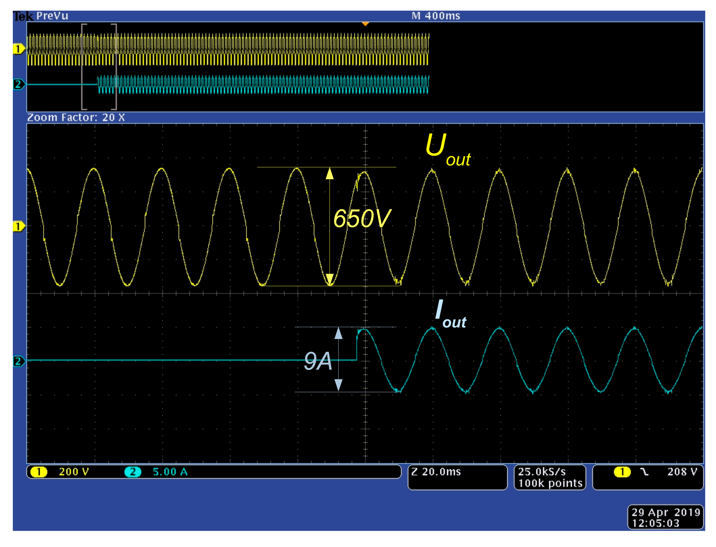
The NZEB is characterized by highly dynamic properties. The load and generation can change rapidly. The ER should be able to respond to those changes by keeping its output voltage stable and sinusoidal. To test these properties, a load step from 0 to 700 W was added to the output of the ER. Figure 11 shows the result of the load step. The current jumped from 0 to about 3.5 Arms while the voltage remained stable at 230 Vrms and 50 Hz.
6. Conclusions
The energy router (ER) can be considered as a key element of the micro- and nanogrids. Through smart energy management the power balance in the micro- and nanogrids can be maintained without utilizing oversized and expensive batteries. Among other active functions, the ER’s goal is to maintain regulated voltage and frequency inside the micro- or nanogrid. In this paper we studied the ER role in the nearly zero energy buildings (NZEB), which can be seen as a hybrid nanogrid. Typically, droop control will be implemented in such systems. However, most conventional power electronic converters in residential or office buildings are not compatible with droop control and new power converters need to be installed. Our goal was to design an ER for the NZEB that would be applicable in conventional buildings with minimal cost and modifications. We proposed a solution where the ER is working as a single grid-forming converter with predefined voltage reference. In this case the most challenging operation point is the idle operation that happens when the load exactly matches the generation within the NZEB.
PR control is a well-known algorithm to regulate sinusoidal signals. Typically, it is used in voltage or current controlled inverters. However, PR control has its limitations. This paper shows that the PR control tends towards instability in small or no-load operation. Thus, it cannot be used in the case of a single grid forming inverter, it should be able to deliver sinusoidal voltage also in idle mode. Our proposal is to use indirect model predictive control (iMPC), which gave good results in both idle and loaded operation mode. The tuning procedure of the iMPC method was explained. As a result, it was found that the dependency between the quality of the output voltage and the horizon prediction p is small. It is shown that the most optimal p value is the simplest case p = 1. Increasing the horizon prediction level would only slightly improve the THD of the output voltage but significantly increase the calculation burden of the controller. The experimental results verified that the proposed iMPC method is capable of regulating the output voltage in both idle and loaded operation mode and it can handle the fast-dynamic nature of NZEB.
The further research includes study of the proposed iMPC method in the case of real non-linear loads in NZEB. In this case also system identification will become an important research topic.
Author Contributions
Conceptualization, O.H.; formal analysis, O.H. and M.N.; funding acquisition, I.R.; investigation, I.R. and M.N.; methodology, O.H.; project administration, I.R.; supervision, I.R.; validation, T.J.; writing—original draft, I.R., O.H. and M.N.; writing—review and editing, J.R.
Funding
This research was supported by the Estonian Research Council grant PUT1680, and co-financed by the Estonian Centre of Excellence in Zero Energy and Resource Efficient Smart Buildings and Districts, ZEBE, grant 2014-2020.4.01.15-0016 funded by the European Regional Development Fund.
Conflicts of Interest
The authors declare no conflict of interest.
References
- Liu, Y.; Fang, Y.; Li, J. Interconnecting microgrids via the energy router with smart energy management. Energies 2017, 10, 1297. [Google Scholar]
- Huang, A.Q.; Crow, M.L.; Heydt, G.T.; Zheng, J.P.; Dale, S.J. The future renewable electric energy delivery and management (FREEDM) system: The energy internet. IEEE 2011, 99, 133–148. [Google Scholar] [CrossRef]
- Fu, R.; Remo, T.; Margolis, R. 2018 U.S. Utility-Scale Photovoltaics Plus-Energy Storage System Costs Benchmark. Report of National Renewable Energy Laboratory. Available online: www.nrel.gov/publications (accessed on 22 March 2019).
- Liu, Y.; Li, Y.; Liang, H.; He, J.; Cui, H. Energy routing control strategy for integrated microgrids including photovoltaic, battery-energy storage and electric vehicles. Energies 2019, 12, 302. [Google Scholar] [CrossRef]
- Ray, O.; Mishra, S. Integrated hybrid output converter as power router for renewable-based nanogrids. In Proceedings of the In IECON 2015—41st Annual Conference of the IEEE Industrial Electronics Society, Yokohama, Japan, 9–12 November 2015; pp. 001645–001650. [Google Scholar]
- Zhen, L.; Penghua, L.; Wanxing, S.; Songhuai, D.; Qing, D.; Zhipeng, L. Research on a household energy router for energy internet. In Proceedings of the 2018 13th IEEE Conference on Industrial Electronics and Applications (ICIEA), Wuhan, China, 31 May–2 June 2018; pp. 952–957. [Google Scholar]
- Hagh, M.T.; Aghdam, F.H. Smart hybrid nanogrids using modular multiport power electronic interface. In Proceedings of the 2016 IEEE Innovative Smart Grid Technologies—Asia (ISGT-Asia), Melbourne, Australia, 28 November–1 December 2016; pp. 618–623. [Google Scholar]
- Mishra, S.; Ray, O. Advances in nanogrid technology and its integration into rural electrification in India. In Proceedings of the 2014 International Power Electronics Conference (IPEC-Hiroshima 2014—ECCE ASIA), Hiroshima, Japan, 18–21 May 2014; pp. 2707–2713. [Google Scholar]
- Pedrasa, M.; Spooner, T. A survey of techniques used to control microgrid generation and storage during island operation. Available online: https://pdfs.semanticscholar.org/01f7/e8ceb853c7bc1073ad390b3dc6736ca31c41.pdf (accessed on 29 April 2019).
- Engler, A.; Soultanis, N. Droop control in LV-grids. In Proceedings of the 2005 International Conference on Future Power Systems, Amsterdam, The Netherlands, 18 November 2005; p. 6. [Google Scholar]
- Shoeiby, B.; Davoodnezhad, R.; Holmes, D.G.; McGrath, B.P. A resonant current regulator based microgrid control strategy with smooth transition between islanded and grid-connected modes. In Proceedings of the 2014 IEEE 5th International Symposium on Power Electronics for Distributed Generation Systems (PEDG), Galway, Ireland, 24–27 June 2014. [Google Scholar]
- Roasto, I.; Rosin, A.; Jalakas, T. Power electronic interface converter for resource efficient buildings. In Proceedings of the IECON 2017—43rd Annual Conference of the IEEE Industrial Electronics Society, Beijing, China, 29 October–1 November 2017; pp. 3638–3643. [Google Scholar]
- Roasto, I.; Rosin, A.; Jalakas, T. Multiport interface converter with an energy storage for nanogrids. In Proceedings of the IECON 2018—44th Annual Conference of the IEEE Industrial Electronics Society, Washington, DC, USA, 21–23 October 2018; pp. 6088–6093. [Google Scholar]
- Majumder, R. A hybrid microgrid with dc connection at back to back converters. IEEE Trans. Smart Grid 2014, 5, 251–259. [Google Scholar] [CrossRef]
- Boroyevich, D.; Cvetkovic, I.; Dong, D.; Burgos, R.; Wang, F.; Lee, F. Future electronic power distribution systems a contemplative view. In Proceedings of the 2010 12th International Conference on Optimization of Electrical and Electronic Equipment, Basov, Romania, 20–22 May 2010; pp. 1369–1380. [Google Scholar]
- Blaabjerg, F.; Teodorescu, R.; Liserre, M.; Timbus, A.V. Overview of control and grid synchronization for distributed power generation systems. IEEE Tran. Ind. Electron. 2006, 53, 1398–1409. [Google Scholar] [CrossRef]
- Timbus, A.; Liserre, M.; Teodorescu, R.; Rodriguez, P.; Blaabjerg, F. Evaluation of current controllers for distributed power generation systems. IEEE Trans. Power Electron. 2009, 24, 654–664. [Google Scholar] [CrossRef]
- Zeng, Z.; Yang, H.; Zhao, R.; Cheng, C. Topologies and control strategies of multi-functional grid-connected inverters for power quality enhancement: A comprehensive review. Renew. Sust. Energ. Rev. 2013, 24, 223–270. [Google Scholar] [CrossRef]
- Husev, O.; Chub, A.; Romero-Cadaval, E.; Roncero-Clemente, C.; Vinnikov, D. Hysteresis current control with distributed shoot-through states for impedance source inverters. Int. J. Circuit Theory Appl. 2015, 44, 783–797. [Google Scholar] [CrossRef]
- Rodriguez, J.; Kolar, J.; Espinoza, J.; Rivera, M.; Rojas, C. Predictive torque and flux control of an induction machine fed by an indirect matrix converter with reactive power minimization. In Proceedings of the 2010 IEEE International Symposium on Industrial Electronics, Bari, Italy, 4–7 July 2010; pp. 3177–3183. [Google Scholar]
- Kennel, R.; Linder, A. Predictive control of inverter supplied electrical drives. Proceedings of 2000 IEEE 31st Annual Power Electronics Specialists Conference. Conference Proceedings (Cat. No.00CH37018), Galway, Ireland, 23 June 2000. [Google Scholar]
- Gholami-Khesht, H.; Monfared, M. Deadbeat direct power control for grid connected inverters using a full-order observer. In Proceedings of the 2015 4th International Conference on Electric Power and Energy Conversion Systems (EPECS), Sharjah, UAE, 24–26 November 2015; pp. 1–5. [Google Scholar]
- Buso, S.; Caldognetto, T.; Brandao, D.I. Oversampled dead-beat current controller for voltage source converters. In Proceedings of the 2015 IEEE Applied Power Electronics Conference and Exposition (APEC), Charlotte, NC, USA, 15–19 March 2015; pp. 1493–1500. [Google Scholar]
- Wang, L.; Ertugrul, N.; Kolhe, M. Evaluation of dead beat current controllers for grid connected converters. In Proceedings of the IEEE PES Innovative Smart Grid Technologies, Tianjin, China, 21–24 May 2012; pp. 1–7. [Google Scholar]
- Jiao, J.; Nelms, R.M. Regulating output impedance using a PI controller to improve the stability of a single phase inverter under weak grid. In Proceedings of the 2016 IEEE 16th International Conference on Environment and Electrical Engineering (EEEIC), Florence, Italy, 7–10 June 2016; pp. 1–6. [Google Scholar]
- Sato, Y.; Ishizuka, T.; Nezu, K.; Kataoka, T. A new control strategy for voltage-type PWM rectifiers to realize zero steady-state control error in input current. IEEE Trans. Ind. Appl. 1998, 34, 480–486. [Google Scholar] [CrossRef]
- Chattopadhyay, R.; De, A.; Bhattacharya, S. Comparison of PR controller and damped PR controller for grid current control of LCL filter based grid-tied inverter under frequency variation and grid distortion. In Proceedings of the 2014 IEEE Energy Conversion Congress and Exposition (ECCE), Pittsburgh, PA, USA, 14–18 September 2014; pp. 3634–3641. [Google Scholar]
- Husev, O.; Roncero-Clemente, C.; Makovenko, E.; Pimentel, S.P.; Vinnikov, D.; Martins, J. Optimization and implementation of the proportional-resonant controller for grid-connected inverter with significant computation delay. IEEE Trans. Ind. Electron. 2019, 1. [Google Scholar] [CrossRef]
- Cutler, R.; Ramaker, B.L. Dynamic Matrix Control—A Computer Control Algorithm. Available online: https://www.infona.pl/resource/bwmeta1.element.ieee-art-000004232009 (accessed on 20 April 2019).
- Richalet, J.; Rault, A.; Testud, J.D.; Papon, J. Model predictive heuristic control: applications to industrial processes. Automatica 1978, 14, 413–428. [Google Scholar] [CrossRef]
- Vazquez, S.; Rodriguez, J.; Rivera, M.; Franquelo, L.G.; Norambuena, M. Model Predictive control for power converters and drives: Advances and trends. IEEE Trans. Ind. Electron. 2017, 64, 935–947. [Google Scholar] [CrossRef]
- Rodriguez, J.; Kazmierkowski, M.P.; Espinoza, J.; Zanchetta, P.; Abu-Rub, H.; Young, H.A.; Rojas, C.A. State of the art of finite control set model predictive control in power electronics. IEEE Trans. Ind. Inf. 2013, 9, 1013–1016. [Google Scholar] [CrossRef]
- Anas, A.; Ellis, M.J.; Bernal, J.E.T.; Wenzel, M.J. Practice-Oriented System Identification Strategies for MPC of Building Thermal and HVAC Dynamics. Available online: https://docs.lib.purdue.edu/cgi/viewcontent.cgi?article=1254&context=ihpbc (accessed on 21 April 2019).
- Ellis Matthew, J.; Alanqar, A. Formulation and Application of an Economic Model Predictive Control Scheme for Thermostats. Available online: https://docs.lib.purdue.edu/cgi/viewcontent.cgi?article=1262&context=ihpbc (accessed on 18 April 2019).
- Zhang, Z.; Li, Z.; Kazmierkowski, M.P.; Rodriguez, J.; Kennel, R. Robust predictive control of three-level npc back-to-back converter pmsg wind turbine systems with revised predictions. IEEE Trans. Power Electron. 2018, 33, 9588–9598. [Google Scholar]
- Zhang, X.; Tan, L.; Xian, J.; Zhang, H.; Ma, Z.; Kang, J. Direct grid-side current model predictive control for grid-connected inverter with LCL filter. IET Power Electron. 2018, 11, 2450–2460. [Google Scholar] [CrossRef]
- Moreno, J.C.; Huerta, J.M.E.; Gil, R.G.; González, S.A. A robust predictive current control for three-phase grid-connected inverters. IEEE Trans. Ind. Electron. 2009, 56, 1993–2004. [Google Scholar] [CrossRef]
- Wang, X.; Zou, J.; Peng, Y.; Xie, C.; Li, K.; M, J.; Zapata, G. Elimination of zero sequence circulating currents in paralleled three-level T-type inverters with a model predictive control strategy. IET Power Electron. 2008, 11, 2573–2581. [Google Scholar] [CrossRef]
- Yang, G.; Hao, S.; Fu, C.; Chen, Z. Model predictive direct power control based on improved T—Type Grid Connected Inverter. IEEE J. Emerg. Sel. Top. Power Electron. 2018, 7, 252–260. [Google Scholar] [CrossRef]
Figure 1.
The structure of the energy router for a nearly zero energy building (NZEB).
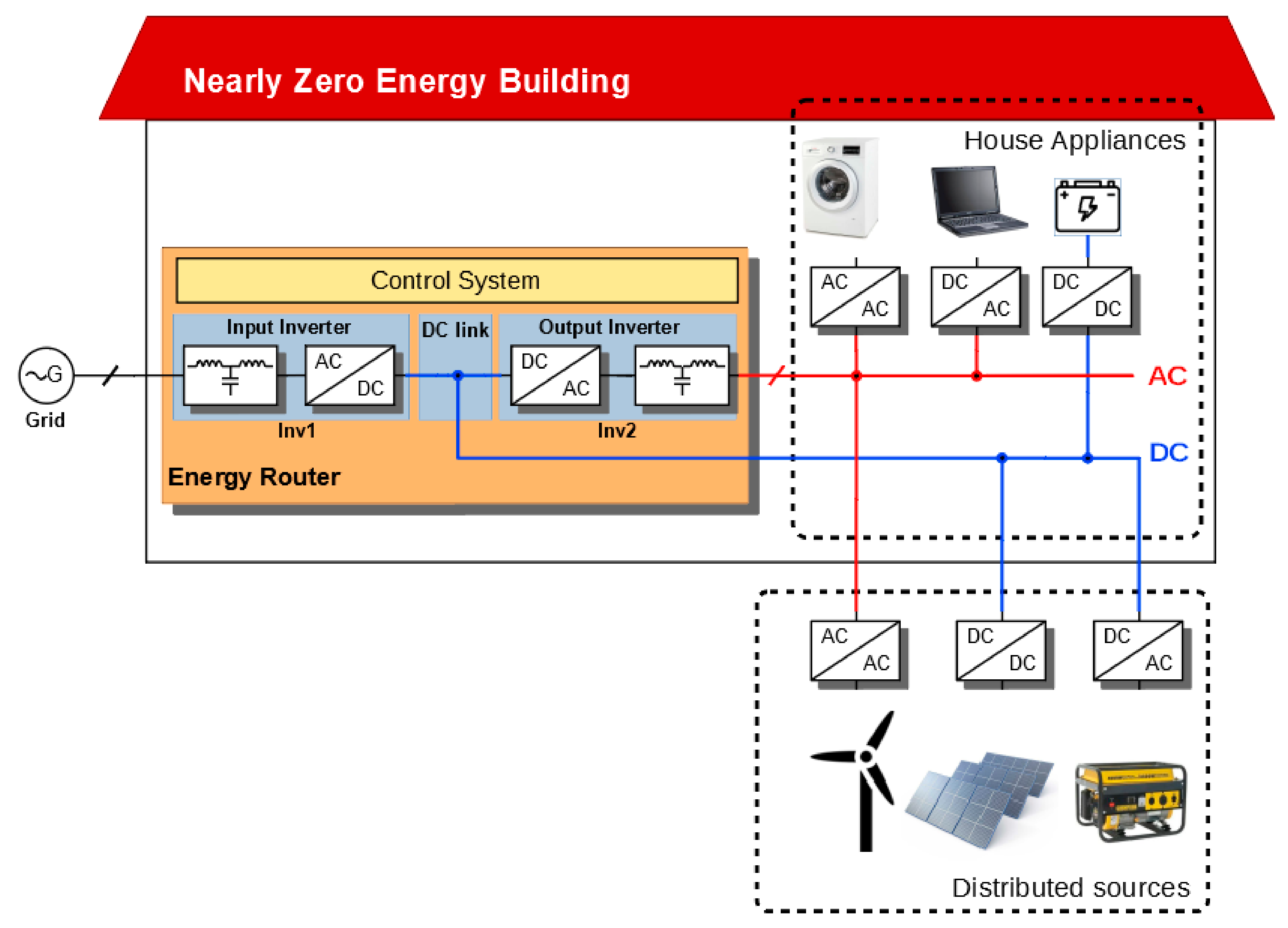
Figure 2.
Model of the energy router (ER) output inverter with LCL filter and proportional-resonant (PR) voltage regulator.
Figure 2.
Model of the energy router (ER) output inverter with LCL filter and proportional-resonant (PR) voltage regulator.
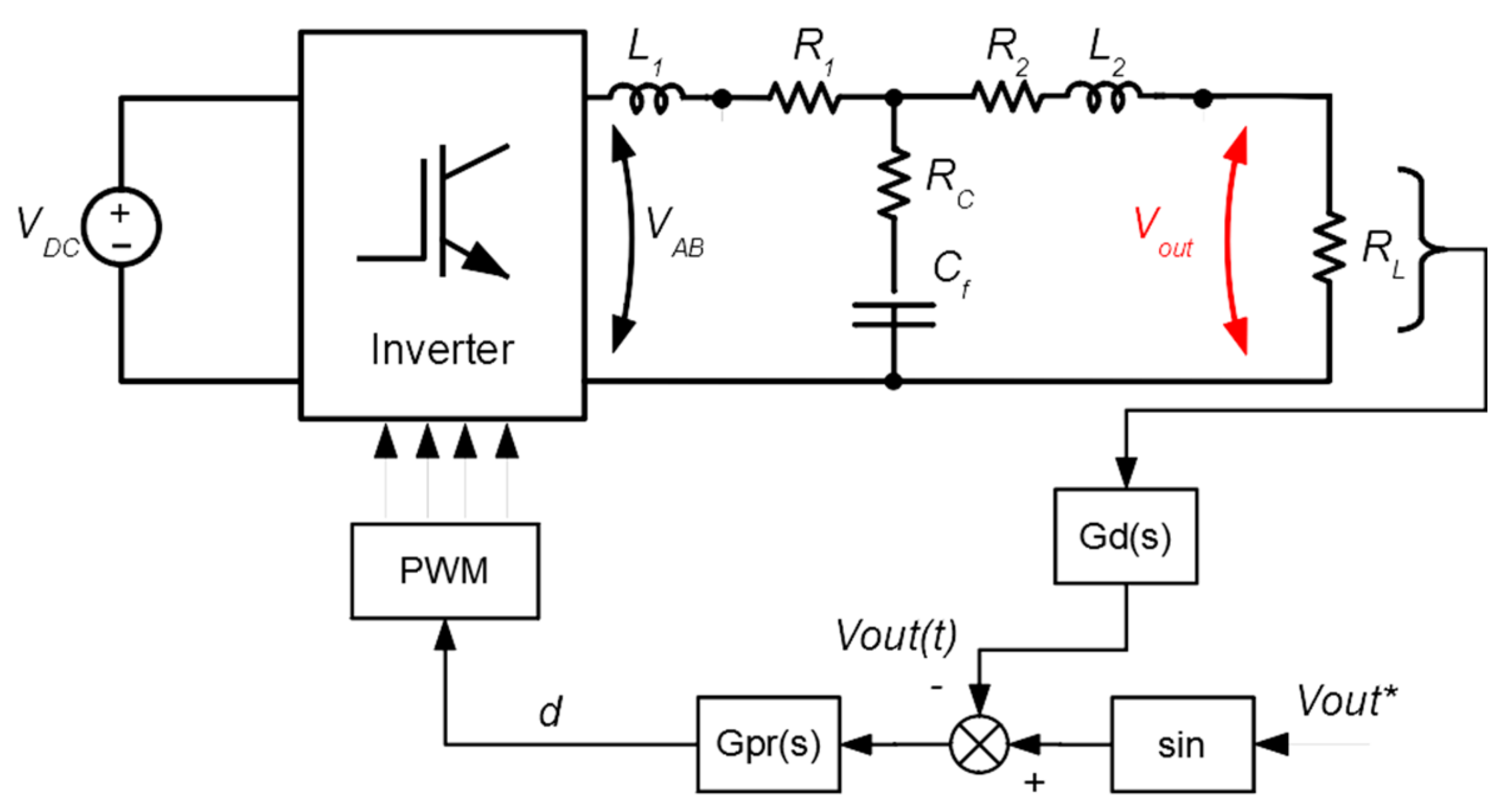
Figure 3.
Pole-zero tendency map in Z-domain for different load resistance values.
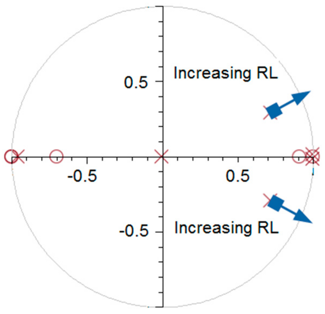
Figure 4.
Equivalent circuit of the output filter (a) along with the control system structure (b).

Figure 5.
Proposed indirect model predictive control (iMPC) approach.
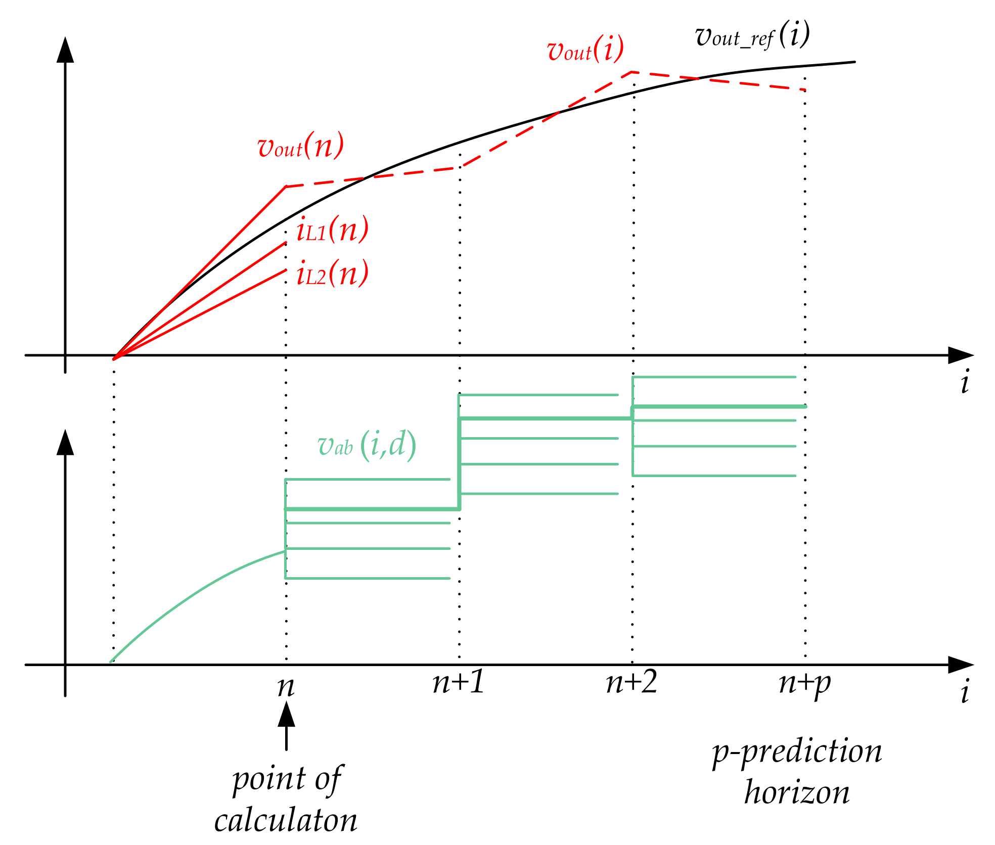
Figure 6.
Output voltage waveforms under different deviation voltage values for the horizon prediction p = 1: ∆vab_max = 40 V (a), ∆vab_max = 5 V (b).
Figure 6.
Output voltage waveforms under different deviation voltage values for the horizon prediction p = 1: ∆vab_max = 40 V (a), ∆vab_max = 5 V (b).

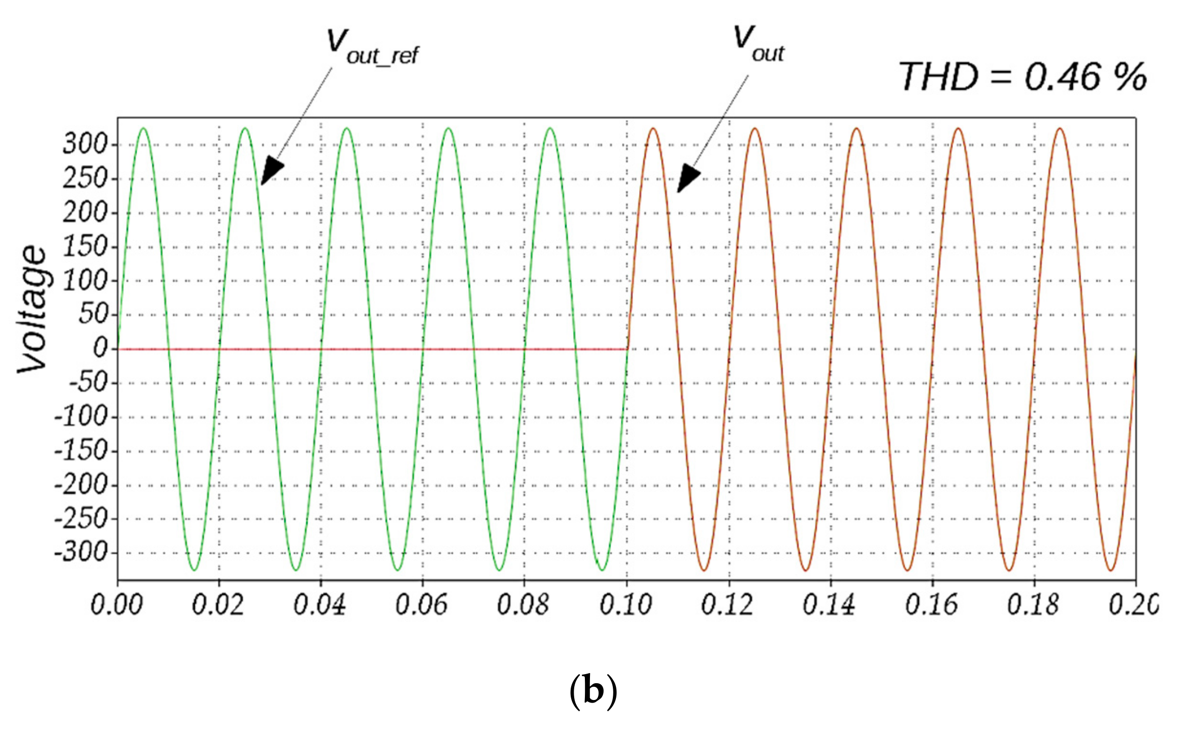
Figure 7.
Output voltage waveforms under different deviation voltage values for the horizon prediction p = 2: ∆vab_max = 40 V (a), ∆vab_max = 5 V (b).
Figure 7.
Output voltage waveforms under different deviation voltage values for the horizon prediction p = 2: ∆vab_max = 40 V (a), ∆vab_max = 5 V (b).
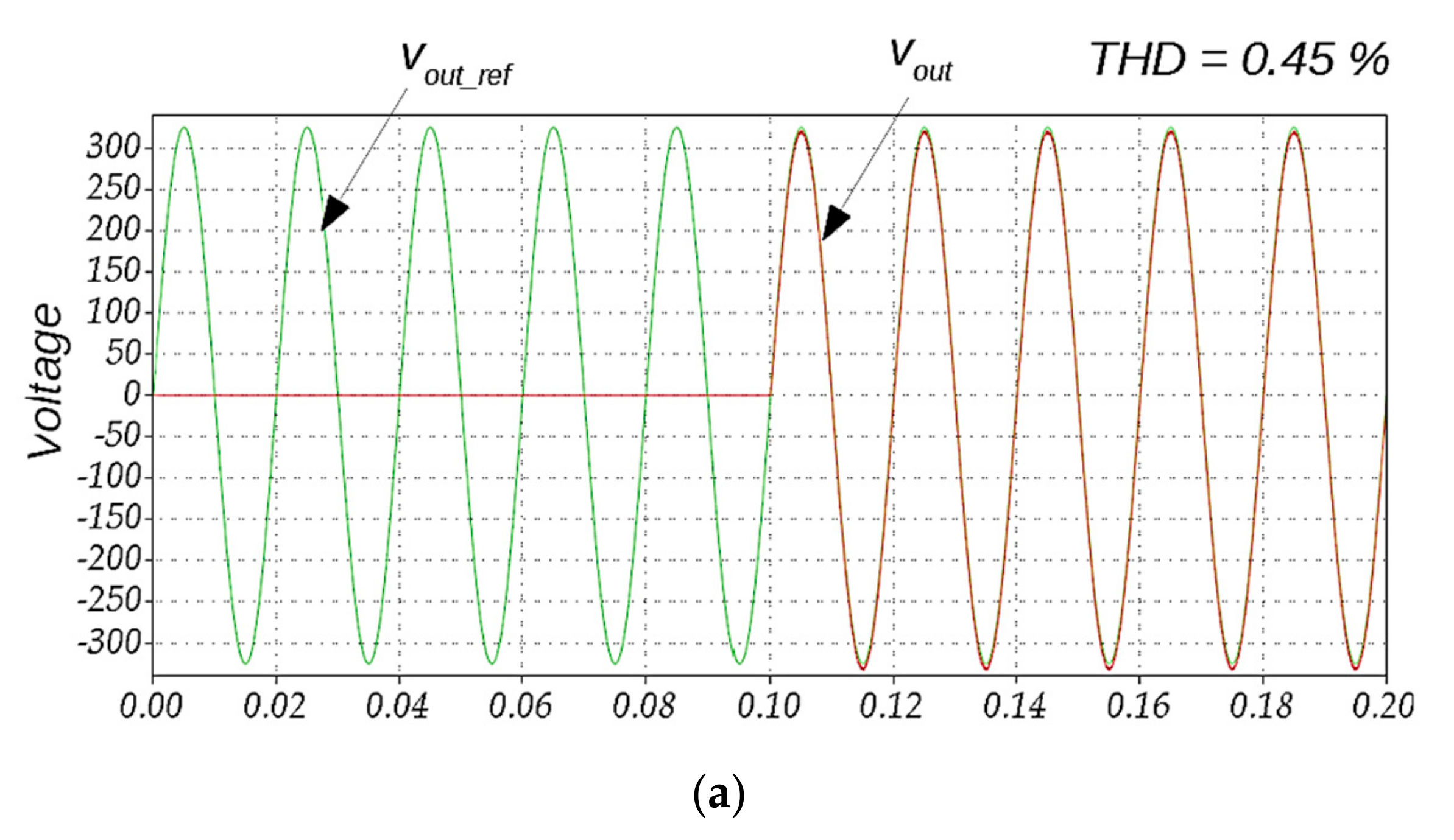

Figure 8.
Experimental prototype of the energy router.

Figure 9.
Unstable operation of the PR regulator in the idle mode.

Figure 10.
ER output voltage in idle operation mode.
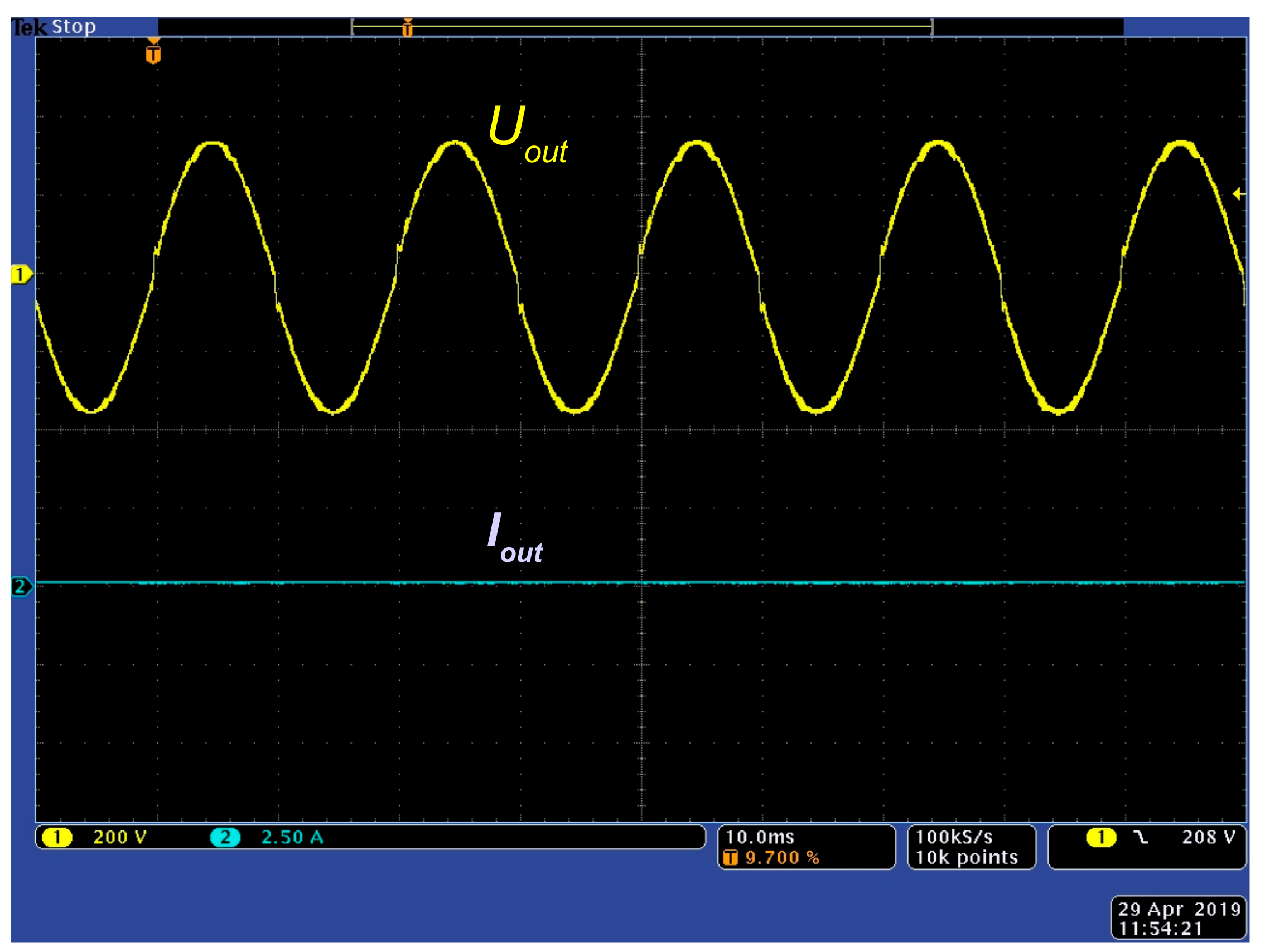
Figure 11.
Inverter output voltage and current at the power step from 0 to 700 W.

Table 1.
Components and parameters of the inverter used for simulation and experiments.
| Parameter | Value |
|---|---|
| Power step in experiments | 0–700 W |
| Input DC voltage VIN | 400 V |
| Output AC RMS voltage VOUT | 230 V |
| Inverter side inductor L1 | 1.44 mH |
| Resistance of L1 windings R1 | 0.05 Ω |
| Output side inductor L2 | 0.6 mH |
| Resistance of L2 windings R2 | 0.03 Ω |
| Filter capacitor Cf | 9.6 µF |
| Resistance of Cf RC | 0.5 Ω |
| Sampling frequency fS | 20 kHz |
| Switching frequency fSW | 20 kHz |
© 2019 by the authors. Licensee MDPI, Basel, Switzerland. This article is an open access article distributed under the terms and conditions of the Creative Commons Attribution (CC BY) license (http://creativecommons.org/licenses/by/4.0/).
Share and Cite
MDPI and ACS Style
Roasto, I.; Husev, O.; Najafzadeh, M.; Jalakas, T.; Rodriguez, J. Voltage Source Operation of the Energy-Router Based on Model Predictive Control. Energies 2019, 12, 1892. https://doi.org/10.3390/en12101892
AMA Style
Roasto I, Husev O, Najafzadeh M, Jalakas T, Rodriguez J. Voltage Source Operation of the Energy-Router Based on Model Predictive Control. Energies. 2019; 12(10):1892. https://doi.org/10.3390/en12101892
Chicago/Turabian StyleRoasto, Indrek, Oleksandr Husev, Mahdiyyeh Najafzadeh, Tanel Jalakas, and Jose Rodriguez. 2019. "Voltage Source Operation of the Energy-Router Based on Model Predictive Control" Energies 12, no. 10: 1892. https://doi.org/10.3390/en12101892
Note that from the first issue of 2016, this journal uses article numbers instead of page numbers. See further details here.