Article

Spherical Shaped ( A g − F e 3 O 4 / H 2 O ) Hybrid Nanofluid Flow Squeezed between Two Riga Plates with Nonlinear Thermal Radiation and Chemical Reaction Effects

1
Department of Mathematics, Faculty of Sciences, HITEC University, Taxila Cantt 47080, Pakistan
2
Department of Mathematics and Statistics, Hazara University, Mansehra 21300, Pakistan
3
Faculty of Mathematics and Statistics, Ton Duc Thang University, Ho Chi Minh City 736464, Vietnam
4
Department of Mechatronics and System Engineering, College of Engineering, Majmaah University, Majmaah 11952, Kingdom of Saudi Arabia
5
Department of Mathematics, Taibah University, Universities Road, P.O. Box 344 Medina, Kingdom of Saudi Arabia
*
Author to whom correspondence should be addressed.
Energies 2019, 12(1), 76; https://doi.org/10.3390/en12010076
Submission received: 17 November 2018 / Revised: 13 December 2018 / Accepted: 20 December 2018 / Published: 27 December 2018
(This article belongs to the Special Issue Fluid Flow and Heat Transfer)

Abstract

:
The main concern is to explore an electro-magneto hydrodynamic (EMHD) squeezing flow of ( A g F e 3 O 4 / H 2 O ) hybrid nanofluid between stretchable parallel Riga plates. The benefits of the use of hybrid nanofluids, and the parameters associated to it, have been analyzed mathematically. This particular problem has a lot of importance in several branches of engineering and industry. Heat and mass transfer along with nonlinear thermal radiation and chemical reaction effects have also been incorporated while carrying out the study. An appropriate selection of dimensionless variables have enabled us to develop a mathematical model for the present flow situation. The resulting mathematical method have been solved by a numerical scheme named as the method of moment. The accuracy of the scheme has been ensured by comparing the present result to some already existing results of the same problem, but for a limited case. To back our results further we have also obtained the solution by anther recipe known as the Runge-Kutta-Fehlberg method combined with the shooting technique. The error analysis in a tabulated form have also been presented to validate the acquired results. Furthermore, with the graphical assistance, the variation in the behavior of the velocity, temperature and concentration profile have been inspected under the action of various ingrained parameters. The expressions for skin friction coefficient, local Nusselt number and local Sherwood number, in case of ( A g F e 3 O 4 / H 2 O ) hybrid nanofluid, have been derived and the influence of various parameters have also been discussed.

1. Introduction

An unprecedented and staggering development in the field of microfluidics, microelectronics, optical devices, chemical synthesis, transportation, high power engines and microsystems, including mechanical and electrical components, transforms the underpinnings of human life. These expansions further demand efficient cooling techniques, in order to manage the thermal performance, reliability and long-term operational devices. The primitive thermal management techniques (like cooling through liquids) seem to be deficient, in order to meet the challenges of thermal efficiency. Later on, this issue has been resolved by dispersing nano-meter sized structures, within the host fluid, which certainly influences its thermo-mechanical properties. In this regard, Choi [1,2] was considered as the pioneer, who gave this concept and calls it ‘Nanofluid’. Many researchers have proposed various theoretical models for thermal conductivity, by following his footsteps. Maxwell [3] worked on a model for the thermal conductivity which is suitable only for the spherical shaped nanoparticles. Further studies in this area lead us to a variety of models, containing the impact of, particle–particle interactions (i.e., Bruggeman model, 1935) [4], particles shapes (i.e., Hamilton and crosser model 1962) [5] and particles distribution (i.e., Suzuki et al. 1969) [6]. Furthermore, researchers have found a number of articles in the literature that covers the different aspects of the nanofluid. Some of them can be found in the references [7,8,9,10,11,12].
In recent past years, a new class of nanofluids, entitled “Hybrid nanofluid”, have come into existence that bears high thermal conductivity as compared to that of mono nanofluid. They have brought a revolution in various heat transfer applications like nuclear system cooling, generator cooling, electronic cooling, automobile radiators, coolant in machining, lubrication, welding, solar heating, thermal storage, heating and cooling in buildings, biomedical, drug reduction, refrigeration, and defense etc. In the case of a regular nanofluid, the critical issue is either they possess a good thermal conductive network or display a better rheological properties. The nanocomposites (single handedly) do not possess all the possible features which are required for a certain application. Therefore, by an appropriate selection of two or more nanoparticles, hybrid nanofluid can lead us to a homogeneous mixture, which possesses all physicochemical properties of various substances that can hardly be found in an individual substance [13,14].
The distinctive features of hybrid nanofluid have gained the attention of worldwide researchers and therefore a number of research articles have been published over the past few years. By employing a new material design concept, Niihara [15] discussed that the mechanical and thermal properties of the host fluid can be greatly enhanced, by the inclusion of nanocomposites.. Jana et al. [16] examined the thermal efficiency of the host fluid, by incorporating single and hybrid nanoparticles. Suresh et al. [17] takes into account a two-step method in order to synthesize water-based ( A I 2 O 3 C u ) hybrid nanofluid. Their experimental results reveal an improvement in the viscosity and thermal properties of the prepared hybrid nanofluid. In their next study [18], the effects of ( A I 2 O 3 C u ) hybrid nanofluid on the rate of heat transfer have been investigated. Momin [19], in 2013, conducted an experiment to study the impact of mixed convection on the laminar flow of hybrid nanofluid inside an inclined tube. By employing a numerical scheme, Devi and Devi [20] investigated the influence of magneto hydrodynamic flow of H 2 O based ( C u A I 2 O 3 ) hybrid nanofluid, over a porous dilating surface. With the aid of entropy generation, the magneto hydrodynamic flow of water based ( C u A I 2 O 3 ) hybrid nanofluid, inside a permeable channel, has been discussed by Das et al. [21]. Chamkha et al. [22], numerically analyzed, the time dependent conjugate natural convection of water based hybrid nanofluid, within a semicircular cavity The Blasius flow of hybrid nanofluid with water, taken as a base fluid over a convectively heated surface, has been examined by Olatundun and Makinde [23]. Besides, in [24], Hayat and Nadeem incorporated the silver ( A g ) and copper oxide ( C u O ) as nanoparticles within the water, to enhance the rate of heat transfer, over the linearly stretching surface.
These days, researchers have been attracted, to analyze the squeezing flows in various geometries. Due to their significance, they have been involved in many practical and industrial situations, like biomechanics, food processing, and chemical and mechanical engineering. They have also been utilized, in order to examine the formation of lubrication, polymer processing, automotive engines, bearings, injection, gear, appliances etc. These flow phenomena have been observed in different hydro dynamical machines and devices, where the normal velocities are enforced by the moving walls of the channel. Stefan [25] was the pioneer behind this concept. Later on, Shahmohamadi et al. [26] employed an analytical technique, to examine the time-dependent axisymmetric flow of a squeezed nature. Recently, the effects of squeezing flow on nanofluid, confined between parallel plates, have been investigated by M. Sheikholeslami et al. [27]. They also utilized the Adomian’s decomposition method to find the solution of the respective flow model. Khan et al. [28] have taken into account, the viscous dissipation effects along with slip condition, to analyze the two-dimensional squeezing flow of copper-water based nanofluid. For solution methodology, they have employed a variation of the parameters method. In 2017, the squeezing effects on the magneto hydrodynamic flow of Casson fluid (inside a channel) have been thoroughly inspected by Ahmed et al. [29]. They have modelled the respective flow problem and then solved it both numerically (Runge-Kutta scheme of fourth order) and analytically (Variation of parameters method).
Gallites and Lilausis [30] came up with the idea of an electromagnetic actuator device, in order to set up the crossed magnetic and electric fields, that appropriately provoked the wall’s parallel Lorentz forces. The purpose of that device was to control the flow characteristics, which usually have a span wise arrangement of alternating and invariable magnets that specifically mounted a plane surface. The device, sometimes indicated as Riga plate [31], provided an aid to reduce the pressure drag, as well as the friction of submarines, that can be achieved by reducing the turbulence production and a boundary layer separation. A number of research articles have been published, in order to explore the distinctive features of the laminar flow of a fluid due to Riga plate. By assuming the least electrical conductivity effects, Pantokratoras and Magyari [32] investigated the flow behavior along with free convection. 1n 2011, Pantokratoras [33] reported the performance of Blasius flow, enforced by the Riga plate. He also encounterd the Sakiadis flow in his study. Later on, Magyari and Pantokratoras [34] took into account the Blasius flow of the liquid, which at the same time is electrically conducting, induced by Riga surface. The electro magneto hydrodynamic flow of nanofluid, induced by Riga plate along with the slip consequences, have been examined by Ayub et al. [35]. In 2017, Hayat et al. [36], discussed the squeezing flow of a fluid between two parallel Riga plates, together with convective heat transfer. The thermal radiative effects accompanied by chemical reaction, were also a part of their study. Moreover, Hayat et al. [37] investigated the electro magneto squeezing flow of carbon nanotube’s suspended nanofluid between two parallel rotatory Riga plates along with viscous dissipation effects. They have considered the melting heat transfer condition, which basically revealed that the heat conducting process to the solid surface, involved the combine effects of both sensible and melting heat, which significantly enhances the temperature of the solid surface to its melting temperature.
The thermal radiation is a significant mode of heat transfer [38,39], which seems to be dominant, in order to transfer the net amount of heat, even in the existence of free or forced convection. The transfer of heat via radiation have been significantly found in many engineering and industrial applications, including airplanes, space vehicles, satellites, and atomic-force plant. In this context, many researchers have comprehensively discussed the radiative heat transfer phenomena. Some of the most relevant have been found in [40,41,42,43,44].
The literature survey revealed the fact that no single step has been taken in order to analyze the salient features of ( A g F e 3 O 4 / H 2 O ) hybrid nanofluid, between two parallel Riga plates. This article encounters the influential behavior of the viscid flow of ( A g F e 3 O 4 / H 2 O ) hybrid nanofluid between two parallel Riga plates, where the lower plate experiences a stretching velocity, while the upper plate enforces a squeezing flow. The transfer of heat and mass along with nonlinear thermal radiative and chemical reaction effects would also be a part of this study. By employing the suitable similarity transforms, a mathematical model for the present flow situation have been accomplished. Method of moment along with Runge-Kutta-Fehlberg method have been considered to find the solution of the model. Tables have been provided which presents the validity of the acquired results. Furthermore, the graphical aid has been provided, to demonstrate the influence of various ingrained entities, on the velocity and temperature along with concentration profiles. The expressions related to the coefficient of skin friction, local Nusselt number and local Sherwood number have also been developed and discussed with the help of graphs.

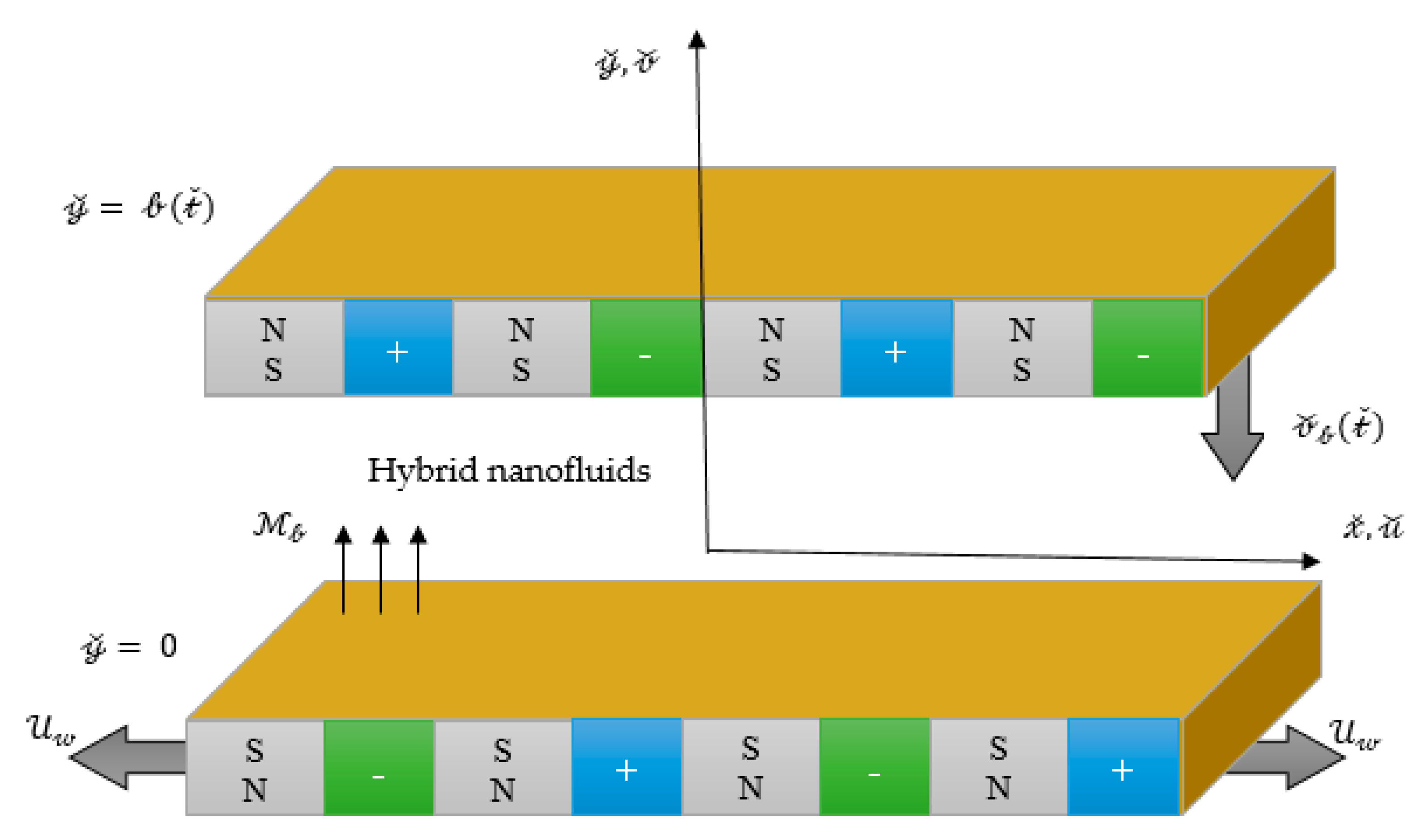
2. Formulation of the Governing Equations

Two parallel Riga plates have been under consideration, among which an electro-magneto hydrodynamic (EMHD) flow of ( A g F e 3 O 4 / H 2 O ) hybrid nanofluid has been flowing. The flow is also time dependent and incompressible. Cartesian coordinates have been chosen in such away, that the 𝓍 ˇ axis coincides with the horizontal direction, whereas the 𝓎 ˇ axis is placed normal to it. The lower plate positioned at 𝓎 ˇ   =   0 , experiences a stretching velocity U 𝓌 ( 𝓍 ˇ ) = 𝒶 𝓍 ˇ / ( 1 λ 𝓉 ˇ ) . Besides, the upper Riga plate, owing the place at 𝓎 ˇ   =   𝒷 ( 𝓉 ˇ ) = λ 2 ( 𝒶 / υ f ( 1 λ 𝓉 ˇ ) ) 0.5 . It is further assumed that the flow of ( A g F e 3 O 4 / H 2 O ) hybrid nanofluid is a squeezing flow, having the velocity 𝓋 ˇ 𝒷 = 𝒹 𝒷 / 𝒹 𝓉 ˇ . Moreover, the nonlinear thermal radiation and chemical reaction effects are also considered. Figure 1 displays the configuration of the flow model.
The Navier-Stokes equations, suitable for the present flow situation, are given as [36]:
𝓋 ˇ 𝓎 ˇ + 𝓊 ˇ 𝓍 ˇ = 0 ,
𝓅 ˇ 𝓍 ˇ + ρ ˇ h n f ( 𝓊 ˇ 𝓉 ˇ + 𝓊 ˇ 𝓍 ˇ 𝓊 ˇ + 𝓊 ˇ 𝓎 ˇ 𝓋 ˇ ) = μ h n f ( 2 𝓊 ˇ 𝓎 ˇ 2 + 2 𝓊 ˇ 𝓍 ˇ 2 ) + E x p ( π 𝓎 ˇ / ) 8 ( π 𝒿 0 0 ) 1 ,
𝓅 ˇ 𝓎 ˇ + ρ ˇ h n f ( 𝓋 ˇ 𝓉 ˇ + 𝓋 ˇ 𝓍 ˇ 𝓊 ˇ + 𝓋 ˇ 𝓎 ˇ 𝓋 ˇ ) = μ h n f ( 2 𝓋 ˇ 𝓎 ˇ 2 + 2 𝓋 ˇ 𝓍 ˇ 2 ) ,
Τ ˇ 𝓉 ˇ + Τ ˇ 𝓍 ˇ 𝓊 ˇ + Τ ˇ 𝓎 ˇ 𝓋 ˇ = 𝓀 h n f ( ρ ^ C p ) h n f ( 2 Τ ˇ 𝓎 ˇ 2 + 2 Τ ˇ 𝓍 ˇ 2 ) 1 ( ρ ˇ C p ) h n f ( q ˇ r 𝓎 ˇ + q ˇ r 𝓍 ˇ ) ,
ˇ 𝓉 ˇ + ˇ 𝓍 ˇ 𝓊 ˇ + ˇ 𝓎 ˇ 𝓋 ˇ = D h n f ( 2 ˇ 𝓎 ˇ 2 + 2 ˇ 𝓍 ˇ 2 ) 𝒸 1 ( ˇ ˇ 𝒷 ) ,
where, 𝓊 ˇ , signifies the horizontal component of velocity, while the vertical one is symbolized by 𝓋 ˇ . The dimensional pressure, temperature and concentration, are respectively shown by 𝓅 ˇ , Τ ˇ and ˇ . Furthermore, denotes the width between magnets and electrodes. 0 ( T e s l a ) represents the magnetization of the permanent magnets, while, 𝒿 0 ( m 2 A ) is the applied current density in the electrodes. The first order coefficient for a chemical reaction, is presented by 𝒸 1 . In addition, q ˇ r symbolizes the rate of heat flux. The expression for the thermal radiative term has been successively proposed by Rosseland [38], which is given as:
q ˇ r = 16 σ ˇ Τ ˇ 3 3 k ˇ Τ ˇ 𝓎 ˇ ,
where, the coefficient for mean absorption is given by k ˇ , while σ ˇ stands for Stefan-Boltzmann constant. Therefore, after incorporating the Equation (6) in Equation (5), the energy equation can be generalized as follows:
Τ ˇ 𝓉 ˇ + Τ ˇ 𝓍 ˇ 𝓊 ˇ + Τ ˇ 𝓎 ˇ 𝓋 ˇ = 𝓀 h n f ( ρ ^ C p ) h n f ( 2 Τ ˇ 𝓎 ˇ 2 + 2 Τ ˇ 𝓍 ˇ 2 ) + 1 ( ρ ˇ C p ) h n f 16 σ ˇ 3 k ˇ 𝓎 ˇ ( Τ ˇ 3 Τ ˇ 𝓎 ˇ ) .
The auxiliary conditions, specifying the current flow situation, are given as:
𝓊 ˇ = U 𝓌 ( 𝓍 ˇ ) = 𝒶 𝓍 ˇ / ( 1 λ 𝓉 ˇ ) , 𝓋 ˇ = 0 , ( Τ ˇ Τ ˇ 0 ) = 0 , (   ˇ ˇ 0 ) = 0 at 𝓎 ˇ = 0 ,
𝓋 ˇ = 𝒹 𝒷 𝒹 𝓉 ˇ = λ 2 ( 𝒶 ( 1 λ 𝓉 ˇ ) υ f ) 0.5 , 𝓊 ˇ = 0 , ( Τ ˇ Τ ˇ 𝒷 ) = 0 , ( ˇ ˇ 𝒷 ) = 0 at 𝓎 ˇ   =   𝒷 ( 𝓉 ˇ ) ,
where, Τ ˇ 0 and Τ ˇ 𝒷 simultaneously, indicates the temperatures of the plates situated at 𝓎 ˇ = 0 and 𝓎 ˇ   =   𝒷 ( 𝓉 ˇ ) . The concentration of nanoparticles at the bottom plate is denoted by ˇ 0 , while, ˇ 𝒷 is the nanoparticles concentration at the top wall. Moreover, the rate, with which the lower surface is being stretched is 𝒶 , while, λ represents the constant characteristics parameter.
In the aforementioned equations, υ f = μ f / ρ ˇ f denotes the effective kinematic viscosity. Furthermore, μ h n f and μ f simultaneously represents the effective dynamic viscosities of the hybrid nanofluid and mono nanofluid that significantly influence the flow behavior of the host fluid. Brinkman [45], in 1952, proposed a model for the effective dynamic viscosity ( μ n f ) of a mono nanofluid which is given below:
μ n f = μ f ( 1 φ ) 5 / 2 ,
where, φ denotes the nanoparticle volume fraction. Thus, in the case of hybrid nanofluid, the effective dynamic viscosity ( μ h n f ) is defined as [22]:
μ h n f = μ f ( 1 φ h ) 5 / 2 ,
where, φ h = φ 1 + φ 2 (in case of hybrid nanofluid) is a net volume fraction of distinct nanoparticles.
The effective density ( ρ ˇ n f ) presented by Pak and Cho [46] and the heat capacity ( ρ ˇ C p ) n f [47] of mono nanofluid, can be respectively given by:
ρ ˇ n f = ρ ˇ f + φ ( ρ ˇ p ρ ˇ f ) ,
( ρ ˇ C p ) n f = ( ρ ˇ C p ) f + φ ( ( ρ ˇ C p ) p ( ρ ˇ C p ) f ) .
By following the rules of mixture principle, the effective density ( ρ ˇ h n f ) [22,48] and heat capacity ( ρ ˇ C p ) h n f [22,48] of hybrid nanofluid, can be estimated via Equations (14) and (15).
ρ ˇ h n f = φ 1 ρ ˇ p 1 + φ 2 ρ ˇ p 2 + ( 1 φ h ) ρ ˇ f ,
( ρ ˇ C p ) h n f = φ 1 ( ρ ˇ C p ) p 1 + φ 2 ( ρ ˇ C p ) p 2 + ( 1 φ h ) ( ρ ˇ C p ) f .
The thermal conductivity ( 𝓀 n f ) is the fundamental property, defining the heat transfer characteristics of the mono nanofluid. Maxwell suggested a correlation [3], for the mono nanofluid, by considering the spherical shaped nanoparticles, whose mathematical expression is given by:
𝓀 n f = 𝓀 f 𝓀 p ( 1 + 2 φ ) + 2 𝓀 f ( 1 φ ) 𝓀 p ( 1 φ ) + 𝓀 f ( 2 + φ ) .
In the case of hybrid nanofluid, the thermal conductivity ratio can be accomplished by modifying the Maxwell correlation [22] as:
𝓀 h n f 𝓀 f = φ 1 𝓀 p 1 + φ 2 𝓀 p 2 φ h + 2 𝓀 f + 2 ( φ 1 𝓀 p 1 + φ 2 𝓀 p 2 ) 2 φ h 𝓀 f φ 1 𝓀 p 1 + φ 2 𝓀 p 2 φ h + 2 𝓀 f ( φ 1 𝓀 p 1 + φ 2 𝓀 p 2 ) + φ h 𝓀 f .
In 1935, another correlation, for spherical nanoparticles, has been introduced by Bruggeman [4], which usually considers the impact of nano clusters on the thermal conductivity. By mixture principle, this model can be extended for the estimation of thermal conductivity ratio of the hybrid nanofluid and is given by:
𝓀 h n f 𝓀 f = 1 4 [ ( 3 φ h 1 ) ( φ 1 𝓀 p 1 + φ 2 𝓀 p 2 φ h 𝓀 f ) + ( 2 3 φ h ) + ( Δ ) 1 / 2 ] ,
where,
Δ = [ ( 3 φ h 1 ) 2 ( φ 1 𝓀 p 1 + φ 2 𝓀 p 2 φ h 𝓀 f ) 2 + ( 2 3 φ h ) 2 + 2 ( 2 + 9 φ h 9 φ h 2 ) ( φ 1 𝓀 p 1 + φ 2 𝓀 p 2 φ h 𝓀 f ) ] .
The molecular diffusivity [22,49,50,51], of the species concentration, for mono nanofluid and hybrid nanofluid are simultaneously defined as:
D n f = ( 1 φ ) D f ,
D h n f = ( 1 φ h ) D f .
In all the above expressions, φ 1 and φ 2 simultaneously, represents the volume concentration of magnetite ( F e 3 O 4 ) and silver ( A g ) nanoparticles in hybrid nanofluids. The viscosity, density and specific heat of host fluid are respectively denoted by μ f ,   ρ ˇ f and ( C p ) f . At constant pressure, ( C p ) p 1 and ( C p ) p 2 respectively, denotes the specific heat of magnetite and silver nanoparticles. The densities, of magnetite and silver nanoparticles, are specified by ρ ˇ p 1 and ρ ˇ p 2 respectively. 𝓀 f and D f represents the thermal conductivity and mass diffusivity of the water ( H 2 O ) . The thermal conductivities of magnetite and silver nanocomposites, are respectively symbolized by 𝓀 p 1 and 𝓀 p 2 .
The prescribed form of similarity transforms, which deals with the process of conversion of Equations (1)–(3) and (7) into a nonlinear set of ordinary differential equations (ODE), are given as:
Ψ = ( ( 1 λ 𝓉 ˇ ) 𝒶 υ f ) 0.5 𝓍 ˇ Ϝ ˇ ( χ ) , χ = 𝓎 ˇ ( 𝒷 ( 𝓉 ˇ ) ) 1 ,    𝓊 ˇ = 𝓎 ˇ ( Ψ ) = U 𝓌 Ϝ ˇ ( χ ) , 𝓋 ^ = 𝓍 ˇ ( Ψ ) = ( ( 1 λ 𝓉 ˇ ) 𝒶 υ f ) 0.5 Ϝ ˇ ( χ ) , T ˇ ( χ ) = Τ ˇ Τ ˇ 𝒷 Τ ˇ 0 Τ ˇ 𝒷 ,    C ˇ ( χ ) = ˇ ˇ 𝒷 ˇ 0 ˇ 𝒷 .
where, the superscript stands for d / d χ . Thus, by opting Brinkman (11) and Bruggeman (18) models, the dimensionless mode of a system of nonlinear ordinary differential equations, for ( A g F e 3 O 4 / H 2 O ) hybrid nanofluid, along with radiation and chemical reaction parameters has been accomplished that can be written as:
Ϝ ˇ i v + Υ ˇ 1 [ Ϝ ˇ Ϝ ˇ Ϝ ˇ Ϝ ˇ γ 2 ( 3 Ϝ ˇ + χ Ϝ ˇ ) ] ( 1 φ h ) 5 / 2 M 𝒷 𝒫 e 𝒫 χ = 0 ,
( ( 𝓀 h n f 𝓀 f + R d ( ( 1 T ˇ ) + T ˇ θ 𝓌 ) 3 ) T ˇ ) + P r Υ ˇ 2 ( Ϝ ˇ γ 2 χ ) T ˇ = 0 .
Θ ˇ + Sc ( 1 φ h ) ( Ϝ ˇ γ 2 χ ) Θ ˇ Sc ( 1 φ h ) 𝒸 Θ ˇ = 0 .
where, Ϝ ˇ , T ˇ and Θ ˇ , all are the dependent functions of dimensionless variable χ . Furthermore, the dimensionless auxiliary conditions, supporting the present flow situation, are therefore suggested as:
Ϝ ˇ ( 0 ) = 0 , Ϝ ˇ ( 1 ) = γ 2 , Ϝ ˇ ( 0 ) 1 = 0 , Ϝ ˇ ( 1 ) = 0 ,
T ˇ ( 0 ) 1 = 0 , T ˇ ( 1 ) = 0 ,
Θ ˇ ( 0 ) 1 = 0 , Θ ˇ ( 1 ) = 0 .
In the above-mentioned system of Equations (23) and (25), γ = λ / 𝒶 represents a dimensionless squeeze number, while, 𝒷 = π 𝒿 0 0 𝓍 ˇ / 8 ρ ˇ f U 𝓌 2 is the modified Hartman number and 𝒫 = π 𝒷 ( 𝓉 ˇ ) / is the dimensionless parameter. Moreover, the radiation parameter is denoted by R d = 16 σ ˇ Τ ˇ 𝒷 3 / 3 k ˇ   𝓀 f . Prandtl number is symbolized by P r = ( 𝓀 f / ( ρ ˇ C p ) f υ f ) 1 . Besides, S c = υ f / D f signifies, the Schmidt number. The chemical reaction is indicated by 𝒸 = 𝒸 1 ( 1 λ 𝓉 ˇ ) / 𝒶 .
Moreover, the constants Υ ˇ 1 and Υ ˇ 2 , embroiled in the governing dimensionless model, can be mathematically stated as:
Υ ˇ 1 = 𝜐 f 𝜐 h n f = ( 1 φ h + φ 1 ρ ˇ p 1 ρ ˇ f + φ 2 ρ ˇ p 2 ρ ˇ f ) ( 1 φ h ) 5 / 2 , Υ ˇ 2 = ( ρ ˇ C p ) h n f ( ρ ˇ C p ) f = 1 φ h + φ 1 ( ρ ˇ C p ) p 1 ( ρ ˇ C p ) f + φ 2 ( ρ ˇ C p ) p 2 ( ρ ˇ C p ) f . }
The coefficient of skin friction, local heat transferal rate (i.e., local Nusselt number) and local Sherwood number, for the present flow situation, opt the following dimensionless expressions:
C ^ f 𝓍 ˇ = τ 𝓌 ρ ˇ h n f U 𝓌 2 ,      N u 𝓍 ˇ = 𝒷 𝓀 f 1 ( Τ ˇ 0 Τ ˇ 𝒷 ) ( q ˇ 𝓌 + q ˇ r )      and      S h 𝓍 ˇ = 𝒷 D f 1 ( ˇ 0 ˇ 𝒷 ) q ˇ 𝓂 ,
where, τ 𝓌 indicates the shear stress, while, the heat and mass fluxes, at both of the walls, are simultaneously signifies by q ˇ 𝓌 and q ˇ 𝓂 . They are respectively defined as:
τ 𝓌 = μ h n f ( 𝓊 ˇ 𝓎 ˇ ) 𝓎 ˇ   =   { 0    𝒷 ( 𝓉 ˇ ) ,      q ˇ 𝓌 = 𝓀 h n f ( Τ ˇ 𝓎 ˇ ) 𝓎 ˇ   =   { 0    𝒷 ( 𝓉 ˇ ) ,      q ˇ 𝓂 = D h n f ( ˇ 𝓎 ˇ ) 𝓎 ˇ   =   { 0    𝒷 ( 𝓉 ˇ )
Subsequently, by incorporating Equations (6) and (31) into Equation (30), we finally achieved the dimensionless forms of skin friction, the Nusselt number, and the Sherwood number, both at the top and bottom walls, which can be expressed as:
R e 𝓍 ˇ 0.5 C ^ l o w e r = 1 Υ ˇ 1 Ϝ ˇ ( 0 ) ,         R e 𝓍 ˇ 0.5 C ^ u p p e r = 1 Υ ˇ 1 Ϝ ˇ ( 1 ) ,
( 1 λ 𝓉 ˇ ) 0.5 R e 𝓍 ˇ 0.5 N u l o w e r = ( 𝓀 h n f 𝓀 f + R d ( θ 𝓌 ) 3 ) T ˇ ( 0 ) , ( 1 λ 𝓉 ˇ ) 0.5 R e 𝓍 ˇ 0.5 N u u p p e r = ( 𝓀 h n f 𝓀 f + R d ) T ˇ ( 1 ) ,
and
R e 𝓍 ˇ 0.5 S h l o w e r = ( 1 φ h ) Θ ˇ ( 0 ) ,        R e 𝓍 ˇ 0.5 S h u p p e r = ( 1 φ h ) Θ ˇ ( 1 ) ,
where, R e 𝓍 ˇ = 𝓍 ˇ U 𝓌 / υ f denotes the local Reynolds number.

3. Solution Procedure

Method of moments (MM), one of the sub-class of the method of weighted residual (MWR), has been considered, in order to tackle the system of differential equations coupled with boundary conditions. From an accuracy point of view, a comparison has also been made, between the results achieved by Method of moments (MM) and Runge-Kutta-Fehlberg method (RKF). For this purpose, a mathematical software Maple 16 has been used.

Method of Moments

Let D , an arbitrary differential operator, acting upon Ϝ ˇ ( χ ) generate a function   ( χ ) , which is given as:
D ( Ϝ ˇ ( χ ) ) = ( χ ) .
In order to approximate the solution of the above-mentioned problem, a trial solution has been defined, which is in the form of a linear combination of base function. These basis functions, also hold the property of linearly independence. Mathematically, it can be expressed as:
Ϝ ˇ ( χ ) Ϝ ˜ ( χ ) = ψ 0 + i = 1 n 𝒸 i ψ i ,
where, the essential boundary conditions are usually incorporated in ψ 0 . By substituting back Equation (36) in Equation (35), one can acquired an exact solution, in the form of the trial solution that satisfies the given problem (35), which is an extremely rare situation. More often, it does not satisfies the given problem and therefore, left an expression that represents the error or the residual as under:
˜ ( χ ) = D ( Ϝ ˇ ( χ ) ) ( χ ) 0 .
The proper selection of weights enabled us to construct weighted residual error. The values of unknown constants 𝒸 i ’s have been accomplished after the minimization procedure, that is:
χ ˜ ( χ )   W i ( χ ) d χ = 0 ,     i = 1 , 2 , , n .
The above equation generate a system of algebraic equations, whose solution finally lead us to determine the unknown constants   𝒸 i ’s, and thus, a numerical solution has been obtained after plugging them back into the trial solution.
It is pertinent to mention that the weight functions involved in the method of moments (MM), are defined as:
W i ( χ ) = 𝒸 j 𝒸 j χ j ,     j = 0 , 1 , , n 1 .
For the present flow problem, the system of the trial solution, under consideration, are defined as:
Ϝ ˇ ( χ ) = 4 5 χ 3 17 10 χ 2 + χ + i = 1 5 𝒸 i χ ( χ 1 ) i ,
T ˇ ( χ ) = 1 χ + i = 1 5 d i χ ( χ 1 ) i ,
Θ ˇ ( χ ) = 1 χ + i = 1 5 e i χ ( χ 1 ) i .
By following the procedure as suggested above, the numerical solution has been achieved by substituting the above set of trial solutions into the governing dimensionless system of equations, which are nonlinear in nature. Thus, by assigning some specific values to the parameters, the approximate solution for the velocity and temperature along with concentration profiles are as under:
Ϝ ˇ ( χ ) Ϝ ˜ ( χ ) = 0.0387970586596651373 χ 6 0.135831460629211753 χ 5 + 0.150915945544620123 χ 4 + 0.750688356622255526 χ 3 1.70467856655171612 χ 2 + 1.00010866635438700 χ ,
T ˇ ( χ ) T ˜ ( χ ) = 0.0866389688520037421 χ 6 + 0.500946012785362327 χ 5 1.06954770759623097 χ 4 + 0.911080929453323640 χ 3 0.0448789189043188319 χ 2 1.21096134688613266 χ + 1.0 ,
Θ ˇ ( χ ) Θ ˜ ( χ ) = 0.00281815275323297988 χ 6 + 0.0301378227343711141 χ 5 0.0834665005070162475 χ 4 + 0.0635487269722848497 χ 3 + 0.0509906671544004958 χ 2 1.05839256360080736 χ + 1.0 .
The above solutions are obtained for certain values of parameters, which are given as:
𝛾 = 𝒸 = R d = 0 . 2 , Sc = 0 . 5 , 𝜃 𝓌 = 1 . 1 , 𝒷 = 1 . 5 , 𝒫 = 10 , 𝜑 1 = 𝜑 2 = 0 . 01 .
Table 1 displays some important thermal and physical properties of carrier fluid ( H 2 O ) [52] and the nanoparticles. These values play a key role in order to obtain the above solutions.
The subsequent Table 2, Table 3 and Table 4 respectively, provide a comparison between the results obtained via MM and RKF, for velocity, temperature, and concentration profiles. The values, as suggested above, remains the same for ingrained parameters. From these tables, one can clearly visualize the validity of the acquired results. Furthermore, for the tabulated values, the significant digit is set to 4.
The reliability of the obtained results have been further checked by reproducing the results for Skin friction coefficient, which were previously presented by Hayat et al. [36]. The results were obtained for the regular fluid ( φ 1 = φ 2 = 0 ) . Table 5 has been prepared to check the validity of the obtained results. It has been observed that the results obtained via Method of Moments are in good agreement with the previously existing results. Moreover, Method of Moments offers less computational complexity as compared to Homotopy analysis method. From the table, it has also been detected that the skin friction coefficient displays a decline with the increasing squeezing parameter ( γ ) . However, a reversed behavior has been observed for increasing values of Modified Hartmann number 𝒷 .

4. Results and Discussions

The goal is to graphically elucidate the influential behavior of velocity, temperature and concentration profiles, due to the various ingrained entities. A pictorial view, from Figure 2, Figure 3, Figure 4, Figure 5, Figure 6, Figure 7, Figure 8, Figure 9, Figure 10, Figure 11, Figure 12, Figure 13, Figure 14, Figure 15, Figure 16, Figure 17, Figure 18, Figure 19 and Figure 20, has been presented for the above-mentioned purpose. Figure 2, Figure 3 and Figure 4 displays the performance of velocity profile, under the action of the squeezing parameter, Modified Hartmann number and solid volume fraction. The variations in velocity component Ϝ ˇ ( χ ) , due to squeezing parameter γ , have been depicted in Figure 2a. For γ > 0 , i.e., when the upper plate moves in the downward direction, the fluid nearby the upper wall experiences a force, which in turn enhances the fluid velocity in that region. As γ increases sufficiently, the velocity component Ϝ ˇ ( χ ) also increases and gradually depreciates the reversal behavior of the flow. The velocity component Ϝ ˇ ( χ ) also experiences an increment in the region, adjacent to the upper wall, which is mainly due to the squeezing behavior of the upper plate and this phenomena has been clearly observed through Figure 2b. Figure 3 demonstrates the impact of Modified Hartmann number 𝒷 on the axial and normal components of the velocity distribution. Since the magnetic field experiences an exponential decline, therefore velocity component Ϝ ˇ ( χ ) seems to be increased in the lower region of the channel. The fact behind is that the application of magnetic field generates the Lorentz forces, which in turn opposes the fluid flow. But in the present situation, the magnetic field decreases, so the Lorentz forces decreases and consequently, an increment in velocity has been perceived in the region close to the lower Riga plate. Besides, in the upper half, the velocity displays an opposite behavior as compared to the lower half of the channel, which may be due to the downward squeezing motion of the upper plate. Figure 3b exhibits an increment in the normal component of velocity Ϝ ˇ ( χ ) with the increasing Modified Hartmann number, which is primarily be due to the decreasing effects of Lorentz force. It can be detected from Figure 4a that the axial velocity decreases in the lower region with the increasing nanoparticles concentration, while an opposite behavior has been perceived in the upper portion of the channel. The reason behind is that the nanoparticle’s concentration resists the fluid to move and therefore decreases the fluid velocity. Figure 4b depicts a decline in the normal component of the velocity Ϝ ˇ ( χ ) with increasing nanoparticle’s concentration, which opposes the fluid motion. Moreover, the inset pictures reveal the fact that the velocity for the ( F e 3 O 4 / H 2 O ) nanofluid mostly attains the higher values as compared to the ( A g F e 3 O 4 / H 2 O ) hybrid nanofluid.
The upcoming figures give a pictorial description of the variations in temperature distribution, for various embedded parameters. 
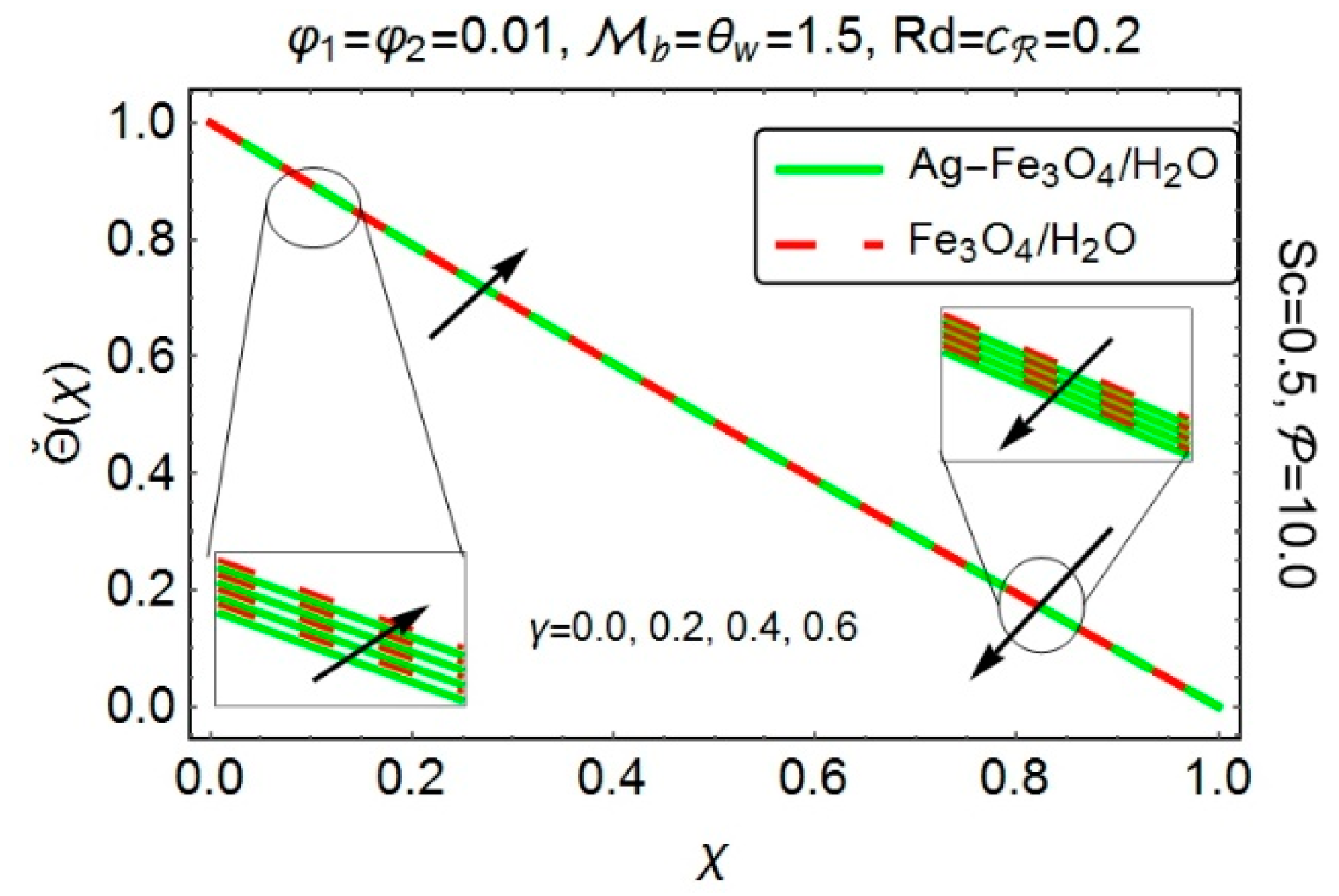
Figure 5 displays the impact of squeezing parameter γ on temperature profile. When the upper plate squeezed down, i.e., γ > 0 
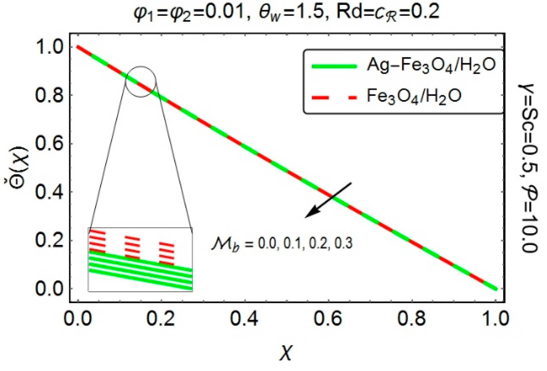
, it exerts a force on the nearby fluid and enhances its velocity, but since the temperature seems to be dominant at the lower wall therefore the fluid in the adjacent region experiences the higher temperature values as compared to the region nearby the channel’s upper wall. To demonstrate the impact of Modified Hartmann number 𝒷 on temperature distribution, Figure 6 has been plotted. It has been found that temperature reveals lower values, as 𝒷 increases. As the impact of Lorentz force on velocity profile produce a friction on the flow, which mainly be responsible to produce more heat energy. In the present flow situation, since the magnetic field exponentially decreases, so the Lorentz force decreases which in turn generates less friction force and consequently, decreases the heat energy and therefore decreases the fluid’s temperature as well as the thermal boundary layer thickness. From Figure 7, one can clearly observe an increment in temperature profile with increasing nanoparticles concentration. The fact behind is that, the inclusion of nanoparticles with different volume fractions augments the thermal properties of the host fluid and therefore increases its temperature. It has also been observed that the temperature of ( A g F e 3 O 4 / H 2 O ) hybrid nanofluid shows its supremacy over the ( F e 3 O 4 / H 2 O ) nanofluid, which definitely be due to the rising values of the thermal conductivity for ( A g F e 3 O 4 / H 2 O ) hybrid nanofluid.
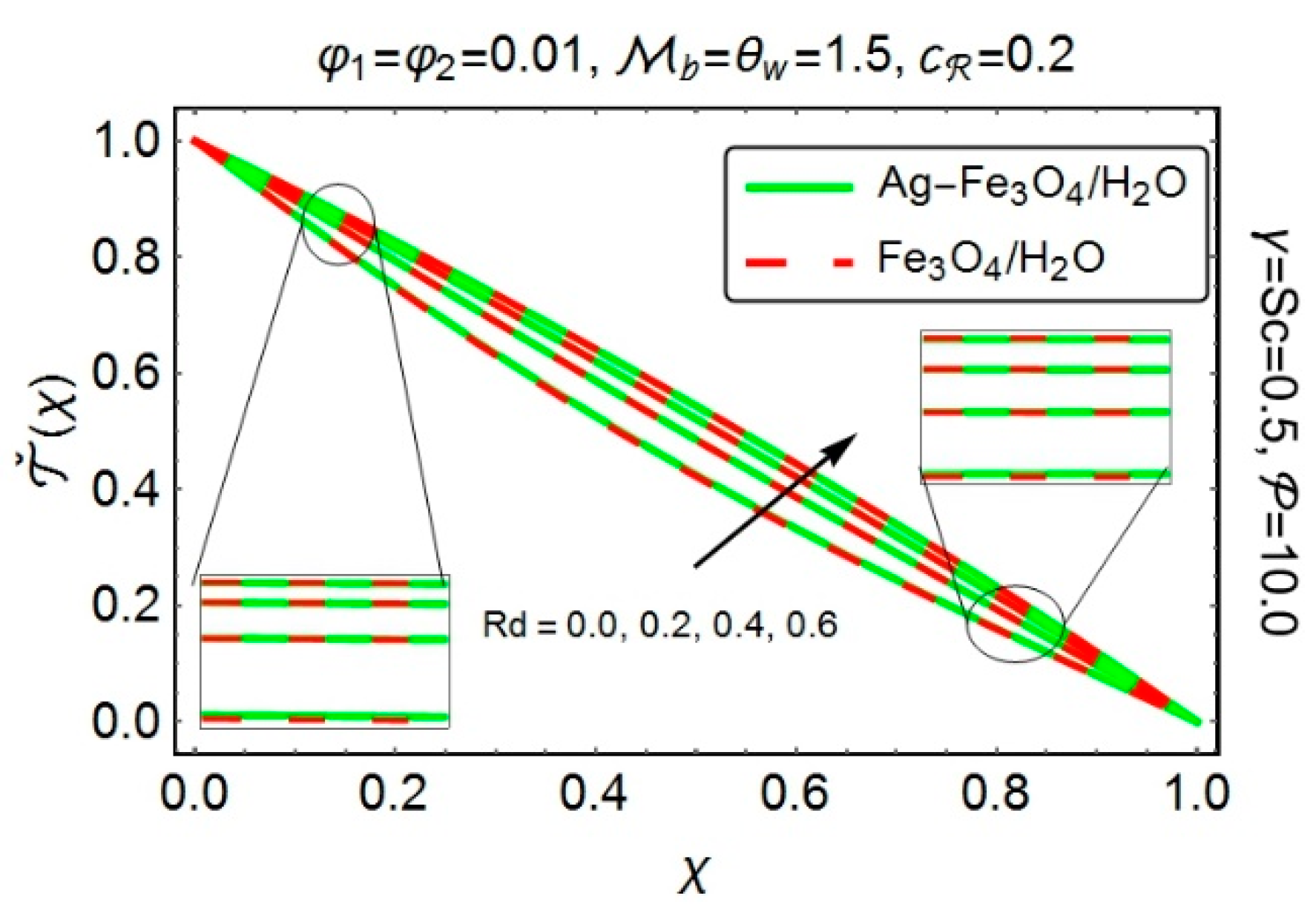
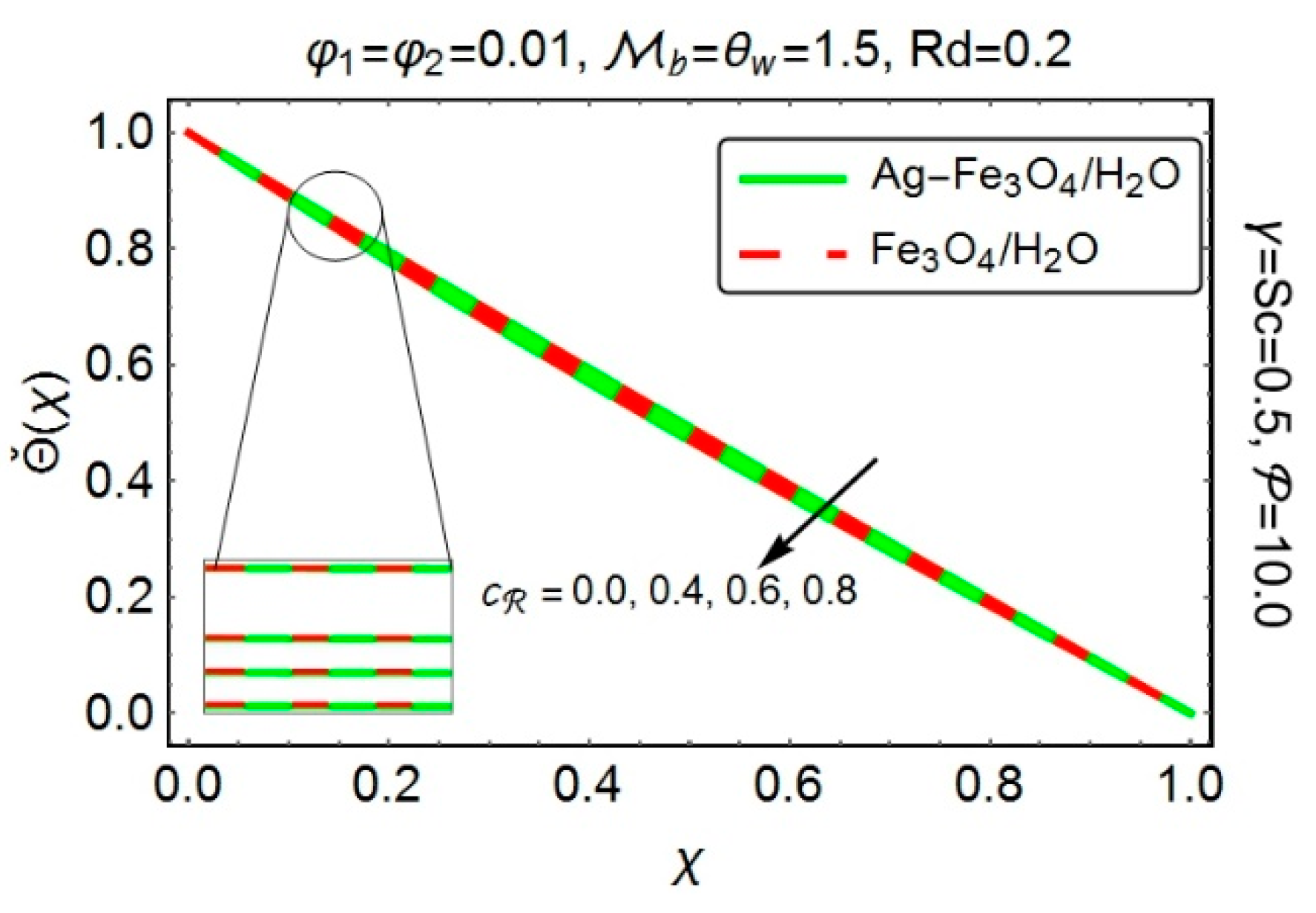
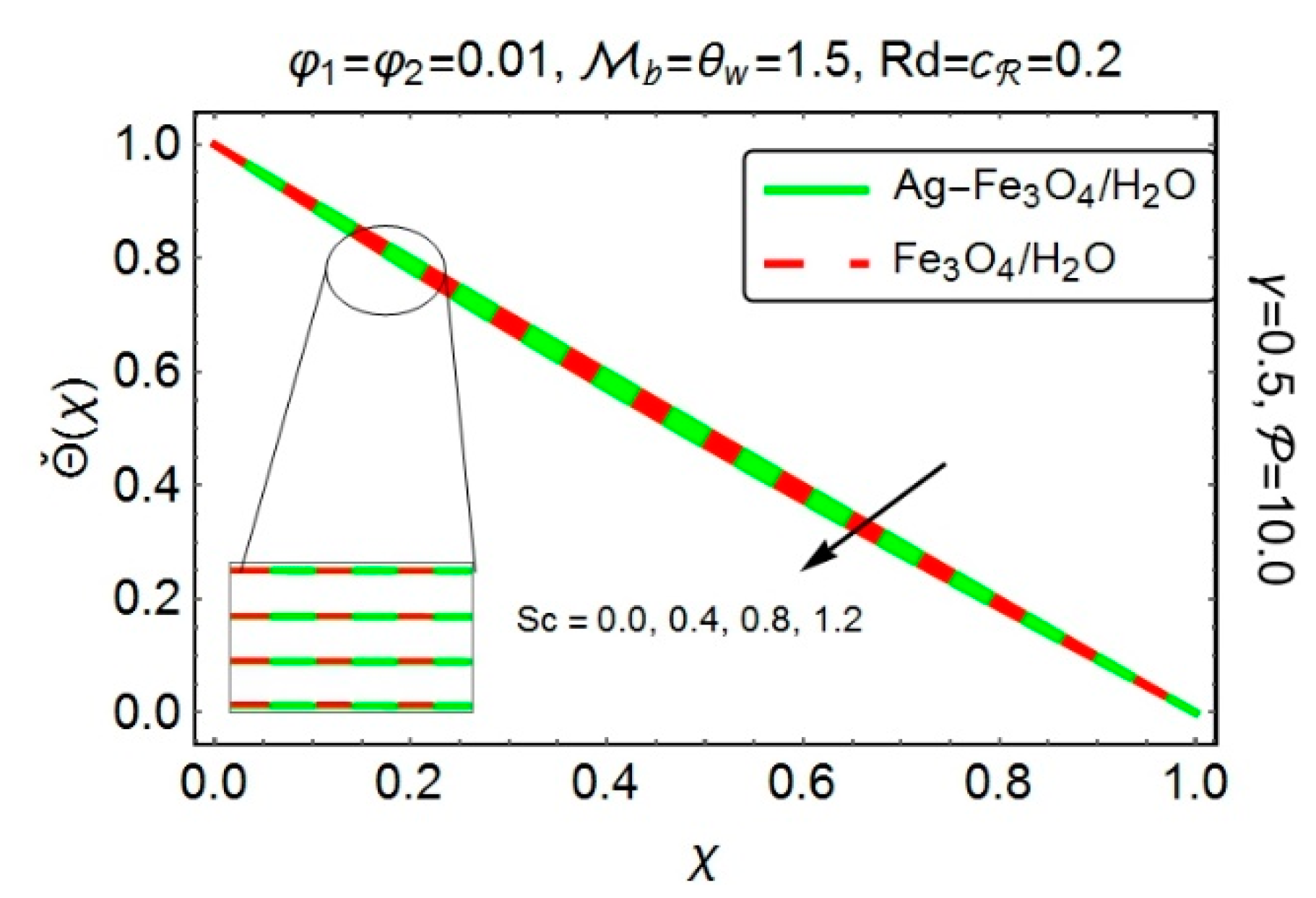
Figure 8 has been sketched, to highlight the temperature behavior under the influence of radiation parameter R d . An upsurge has been encountered in temperature, for increasing R d . The fact behind is that, the increasing R d corresponds to the decrement in mean absorption coefficient, which in turn raises the fluid temperature. The temperature also depicts a rising behavior with increasing θ 𝓌 (see Figure 9). The increasing θ 𝓌 
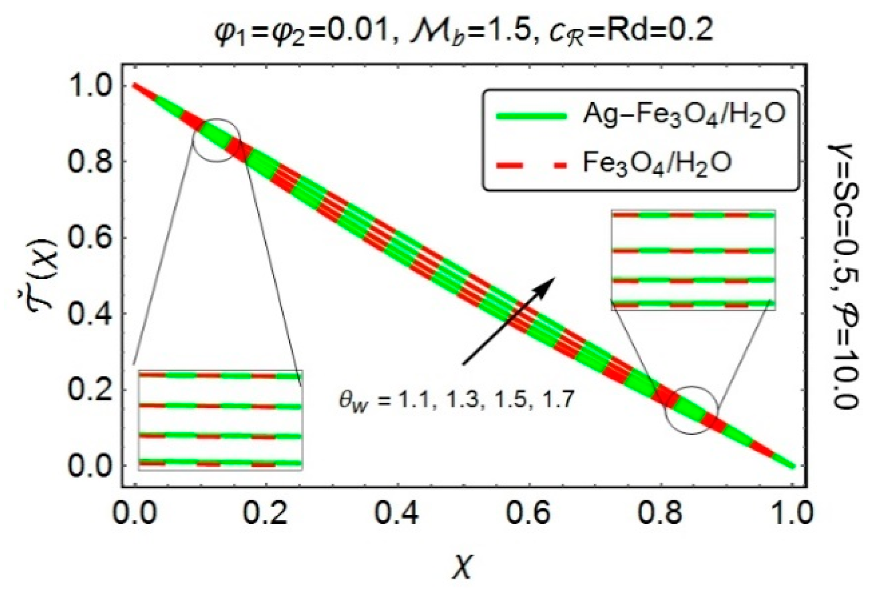
implies that the temperature differences between the lower and upper walls significantly rises and subsequently, an increment in temperature has been recorded.
The next set of figures provide us an aid, to visualize the deviations, in concentration profile, caused by various embedded parameters. Figure 10 demonstrates the influence of squeezing parameter γ on the concentration profile. When the upper plate moves vertically downward, i.e., γ > 0 , it suppresses the adjacent fluid layers and enhances its velocity, but since the concentration shows its supremacy at the lower wall, therefore the concentration profile shows its dominancy in the region, close to the lower wall, as compared to the region adjacent to the upper wall. To demonstrate the impact of Modified Hartmann number 𝒷 on concentration profile, Figure 11 has been painted. As explained earlier that the Lorentz forces, in present flow situation, experience a decline, which as a result generate less friction force and therefore, decrease the concentration profile along with concentration boundary layer thickness. From Figure 12, one can clearly detect a decline in concentration profile, as nanoparticle fraction increases. Moreover, it has been noticed that the concentration profile for ( A g F e 3 O 4 / H 2 O ) hybrid nanofluid possesses lower values as compared to the ( F e 3 O 4 / H 2 O ) nanofluid.
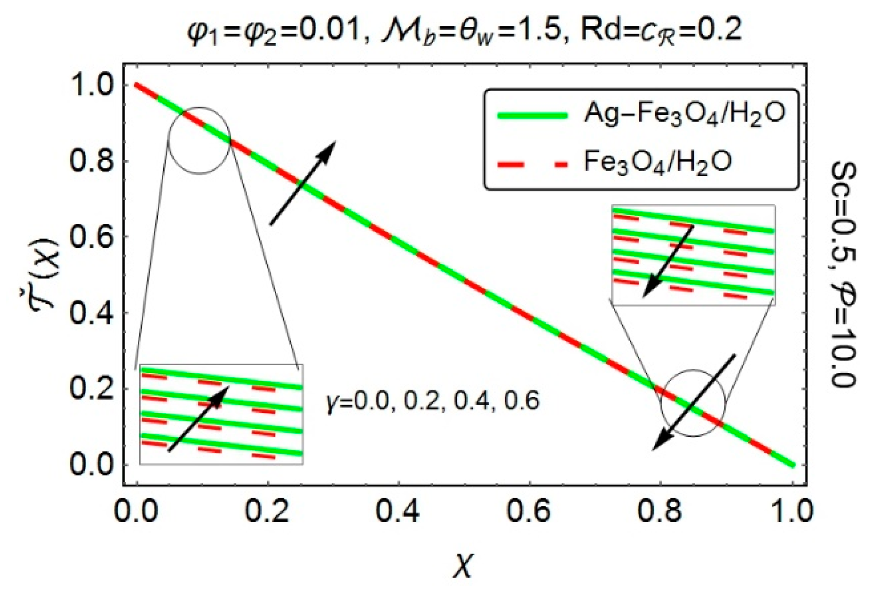
Figure 13 portrays the influence of chemical reaction parameter 𝒸 on concentration profile. A clear decline has been perceived in the concentration of species with the growing values of chemical reaction parameter 𝒸 . Since the chemical reaction, in the present flow analysis, is due to the consumption of the chemicals, therefore, the concentration profile experiences a decline with the increasing values of 𝒸 . The variations in concentration profile, under the action of Schmidt number S c , has been presented in Figure 14. It has been observed that the increasing values of Schmidt number S c causes a decline in the concentration of the species. Since the Schmidt number is the ratio of momentum diffusivity to mass diffusivity. Therefore, the increment in Schmidt number consequently implies a decline in mass diffusivity, which in turn decreases the concentration profile.
Figure 15 and Figure 16 display the impact of various ingrained parameters on the skin friction coefficient, both at the upper and lower Riga surfaces. It has been detected from Figure 15 that increasing the nanoparticles concentration certainly enhances the coefficient of skin friction drag at the lower Riga plate. However, at the upper plate, an opposite behavior has been clearly visible. As far as squeezing parameter γ is concerned, the skin friction coefficient exhibits an increasing behavior, in the region adjacent to the lower plate. However, a decline has been perceived at the upper wall. From Figure 16, one can clearly observes an increment in skin friction coefficient, with the increasing 𝒷 , both at the upper and lower Riga plates. Moreover, the skin friction coefficient for ( A g F e 3 O 4 / H 2 O ) hybrid nanofluid possesses higher values, at the bottom of the channel, as compared to the ( F e 3 O 4 / H 2 O ) nanofluid.
Figure 17 and Figure 18 have been plotted, to assess the consequences of various embedded entities on the local rate of heat transfer i.e., Nusselt number. From Figure 17, one can clearly detect an increment in heat transfer, with increasing nanoparticle volume fraction, at both of the plates. Since the nanoparticle’s inclusion, in the base fluid, is responsible for rising its temperature, therefore an augmentation in the heat transfer rate is quite obvious. By varying the squeezing number γ horizontally, the local Nusselt number at the upper as well as on the lower plates, indicate a decreasing behavior. Figure 18 depicts the variations in heat transfer rate, with growing values of radiation parameter R d and temperature difference parameter θ 𝓌 . Since both the parameters ( R d and θ 𝓌 ) significantly amplifies the temperature of the fluid, therefore, they play a key role in enhancing the local Nusselt number, both at the upper and lower Riga plates. Besides, it has been observed from both the figures that the ( A g F e 3 O 4 / H 2 O ) hybrid nanofluid shows its supremacy in transferring the heat, both at the upper and lower Riga plates.
Figure 19 and Figure 20 depict the variations in the rate of mass transfer, i.e., Sherwood number under the action of various involved parameters. Figure 19 reveals a decline in the Sherwood number with increasing nanoparticle concentration, both at the upper and lower Riga plates. Since the increasing nanoparticle’s volume fraction certainly opposes the fluid motion, therefore a decrement in Sherwood number is quite obvious. The rate, with which mass flows, also shows a decreasing behavior when the squeezing parameter γ increases horizontally. From Figure 20, one can observes a clear enhancement in the rate of mass flow in the region nearby the lower plate, when the chemical reaction parameter 𝒸 increases curve wise and Schmidt number S c varies along the horizontal axis. On the other hand, a reverse behavior has been perceived at the upper plate. Moreover, ( F e 3 O 4 / H 2 O ) nanofluid remains dominant in transferring the mass, both at the upper and lower Riga plates.
Hybrid nanofluids, being advanced version of nanofluids, considerably influences the thermo-mechanical properties of the working fluid, particularly the thermal conductivity. For the said purpose, Table 6 and Table 7 have been designed, to see the deviations in thermo-mechanical properties of the ( A g F e 3 O 4 / H 2 O ) hybrid nanofluid and ( F e 3 O 4 / H 2 O ) nanofluid. It has been detected that the density of ( A g F e 3 O 4 / H 2 O ) hybrid nanofluid depicts an increment, as compared to ( F e 3 O 4 / H 2 O ) nanofluid. While, the specific heat clearly experiences a decline with the increasing nanoparticles fraction. As far as thermal conductivity is concerned, ( A g F e 3 O 4 / H 2 O ) hybrid nanofluid shows a dominant behavior against the ( F e 3 O 4 / H 2 O ) nanofluid. Besides, the Bruggeman model (18), for thermal conductivity shows its proficiency over the Maxwell’s model (17). The reason is that, the Bruggeman model is more focused on the maximum interactions between randomly dispersed particles. It usually involves the spherical shaped particles, with no limitation on the particles concentration. On the other hand, the Maxwell’s model depends on the nanoparticle’s volume fraction and the thermal conductivity of the base fluid and the spherical shaped particles.

5. Conclusions

This article discloses the salient features of nonlinear thermal radiation, in the squeezing flow of ( A g F e 3 O 4 / H 2 O ) hybrid nanofluid, between two Riga plates along with a chemical reaction. Method of moment has been employed for the solution point of view. The obtained results are then compared with the numerical results (obtained via Runge-Kutta-Fehlberg algorithm). Both the methods depict an excellent agreement between the results.
Further investigations are as follows:
  • Velocity profile seems to be an increasing function of both squeezing parameter γ and modified Hartmann number 𝒷 .
  • A decrement in the velocity behavior has been perceived, with increasing nanoparticle concentration.
  • The velocity profile for ( A g F e 3 O 4 / H 2 O ) hybrid nanofluid mostly remains on the lower side.
  • The amplification in temperature has been recorded for increasing squeezed number γ and nanoparticle concentration, while a reversed behavior has been noticed for increasing modified Hartman number 𝒷 .
  • The temperature behaves in an increasing manner with the rising R d and θ 𝓌 . Besides, the temperature profile possesses a dominant behavior for ( A g F e 3 O 4 / H 2 O ) hybrid nanofluid.
  • The concentration profile demonstrates a decreasing behavior, with increasing modified Hartman number 𝒷 and nanoparticle volume fraction.
  • The increment in chemical reaction parameter 𝒸 and Schmidt number S c depicts a clear decline in the concentration profile.
  • Skin friction coefficient for ( A g F e 3 O 4 / H 2 O ) hybrid nanofluid displays an increasing behavior, in the region adjacent to the lower Riga plate, against the varying squeezing parameter γ , modified Hartman number 𝒷 and the nanoparticle concentration.
  • The local heat transfer rate, for ( A g F e 3 O 4 / H 2 O ) hybrid nanofluid, shows its proficiency for varying nanoparticle concentration, radiation parameter R d and temperature difference parameter θ 𝓌 and this phenomena has been detected at both the plates.
  • The augmentation of Schmidt number S c and chemical reaction parameter 𝒸 enhances the Sherwood number, at the lower plate, while a reversed phenomenon has been observed at the upper plate.

Author Contributions

All the authors equally contributed to the paper. Final draft has been read and approved by all the authors.

Funding

This research received no external funding.

Acknowledgments

We are thankful to the anonymous reviewers for their valuable comments which really improved the quality of presented work.

Conflicts of Interest

The authors declare no conflict of interest.

Nomenclature

Width between magnets and electrodes
0 Magnetization of the permanent magnets, T e s l a
𝒿 0 Applied current density in the electrodes, m 2 A
𝒸 1 First order chemical reaction coefficient
D Molecular diffusivity
𝓀 Thermal conductivity, W / m K
𝓅 ˇ Pressure
C p Specific heat at constant pressure,   J / k g . K
𝓊 ˇ   Axial velocity component, m / s
𝓋 ˇ Normal velocity component, m / s
k ˇ Coefficient for mean absorption
𝒷 Modified Hartman number
𝒶 Rate of stretching
𝒸 Chemical reaction parameter
P r Prandtl number
R d Radiation parameter
N u Nusselt number
S c Schmidt number
R e Reynolds number
S h Sherwood number
A g Silver nanoparticles
H 2 O Water
F e 3 O 4 Magnetite nanoparticles
EMHD Electro-magneto hydrodynamic

Greek Symbols

φ Solid volume fraction
μ Dynamic viscosity,   N . s / m 2
ρ ˇ Density, k g / m 3
υ Kinematic viscosity,   m 2 / s
χ Similarity variable
σ ˇ Stefan-Boltzmann constant
λ Constant characteristics parameter
γ Dimensionless squeeze number
θ 𝓌 Temperature difference parameter
ρ ˇ C p Heat capacitance

Subscripts

h n f Hybrid Nanofluid
n f Nanofluid
f Base fluid
p 1 Solid nanoparticles of   F e 3 O 4
p 2 Solid nanoparticles of   A g

References

  1. Choi, S.U.S. Enhancing thermal conductivity of fluids with nanoparticles. In Developments and Applications of Non-Newtonian Flows; Siginer, D.A., Wang, H.P., Eds.; ASME: New York, NY, USA, 1995; Volume 231, pp. 99–105. [Google Scholar]
  2. Choi, S.U.S.; Zhang, Z.G.; Yu, W.; Lockwood, F.E.; Grulke, E.A. Anomalous thermal conductivity enhancement in nanotube suspensions. Appl. Phys. Lett. 2001, 79, 2252–2254. [Google Scholar] [CrossRef]
  3. Maxwell, J.C. A Treatise on Electricity and Magnetism, 3rd ed.; Clarendon; Oxford University Press: Oxford, UK, 1904. [Google Scholar]
  4. Bruggeman, D.A.G. Berechnzcrrg verschCedcner physikalducher Eonstanten von heterogenew Yuhstan.xen 1. Ann. Phys. 1935, 416, 636–664. [Google Scholar] [CrossRef]
  5. Hamilton, R.L.; Crosser, O.K. Thermal conductivity of heterogeneous two-component systems. Ind. Eng. Chem. Fundam. 1962, 1, 187–191. [Google Scholar] [CrossRef]
  6. Suzuki, A.; Ho, N.F.H.; Higuchi, W.I. Predictions of the particle size distribution changes in emulsions and suspensions by digital computation. J. Colloid Interface Sci. 1969, 29, 552–564. [Google Scholar] [CrossRef]
  7. Buongiorno, J. Convective transport in nanofluids. J. Heat Transf. 2006, 128, 240–250. [Google Scholar] [CrossRef]
  8. Xue, Q.Z. Model for thermal conductivity of carbon nanotube-based composites. Phys. B Condens. Matter. 2005, 368, 302–307. [Google Scholar] [CrossRef]
  9. Iijima, S. Helical microtubules of graphitic carbon. Nature 1991, 354, 56–58. [Google Scholar] [CrossRef]
  10. Timofeeva, E.V.; Gavrilov, A.N.; McCloskey, J.M.; Tolmachev, Y.V.; Sprunt, S.; Lopatina, L.M.; Selinger, J.V. Thermal conductivity and particle agglomeration in alumina nanofluids: Experiment and theory. Phys. Rev. E 2007, 76, 061203. [Google Scholar] [CrossRef]
  11. Masoumi, N.; Sohrabi, N.; Behzadmehr, A. A new model for calculating the effective viscosity of nanofluids. J. Phys. D Appl. Phys. 2009, 42, 055501. [Google Scholar] [CrossRef]
  12. Thurgood, P.; Baratchi, S.; Szydzik, C.; Mitchell, A.; Khoshmanesh, K. Porous PDMS structures for the storage and release of aqueous solutions into fluidic environments. Lab Chip 2017, 17, 2517–2527. [Google Scholar] [CrossRef]
  13. Sarkar, J.; Ghosh, P.; Adil, A. A review on hybrid nanofluids: Recent research, development and applications. Renew. Sustain. Energy Rev. 2015, 43, 164–177. [Google Scholar] [CrossRef]
  14. Ranga Babu, J.A.; Kumar, K.K.; Srinivasa Rao, S. State-of-art review on hybrid nanofluids. Renew. Sustain. Energy Rev. 2017, 77, 551–565. [Google Scholar] [CrossRef]
  15. Niihara, K. New Design Concept of Structural Ceramics. J. Ceram. Soc. Jpn. 1991, 99, 974–982. [Google Scholar] [CrossRef]
  16. Jana, S.; Salehi-Khojin, A.; Zhong, W.H. Enhancement of fluid thermal conductivity by the addition of single and hybrid nano-additives. Thermochim. Acta 2007, 462, 45–55. [Google Scholar] [CrossRef]
  17. Suresh, S.; Venkitaraj, K.P.; Selvakumar, P.; Chandrasekar, M. Synthesis of Al2O3-Cu/water hybrid nanofluids using two step method and its thermo physical properties. Colloids Surf. A Physicochem. Eng. Asp. 2011, 388, 41–48. [Google Scholar] [CrossRef]
  18. Suresh, S.; Venkitaraj, K.P.; Selvakumar, P.; Chandrasekar, M. Effect of Al2O3–Cu/water hybrid nanofluid in heat transfer. Exp. Therm. Fluid Sci. 2012, 38, 54–60. [Google Scholar] [CrossRef]
  19. Momin, G.G. Experimental investigation of mixed convection with water-Al2O3 & hybrid nanofluid in inclined tube for laminar flow. Int. J. Sci. Technol. Res. 2013, 2, 195–202. [Google Scholar]
  20. Devi, S.P.A.; Devi, S.S.U. Numerical investigation of hydromagnetic hybrid Cu-Al2O3/water nanofluid flow over a permeable stretching sheet with suction. Int. J. Nonlinear Sci. Numer. 2016, 17, 249–257. [Google Scholar] [CrossRef]
  21. Das, S.; Jana, R.N.; Makinde, O.D. MHD Flow of Cu-Al2O3/Water Hybrid Nanofluid in Porous Channel: Analysis of Entropy Generation. Defect Diffus. Forum 2017, 377, 42–61. [Google Scholar] [CrossRef]
  22. Chamkha, A.J.; Miroshnichenko, I.V.; Sheremet, M.A. Numerical analysis of unsteady conjugate natural convection of hybrid water-based nanofluid in a semi-circular cavity. J. Therm. Sci. Eng. Appl. 2017, 9, 1–9. [Google Scholar] [CrossRef]
  23. Olatundun, A.T.; Makinde, O.D. Analysis of Blasius flow of hybrid nanofluids over a convectively heated surface. Defect Diffus. Forum 2017, 377, 29–41. [Google Scholar] [CrossRef]
  24. Hayat, T.; Nadeem, S. Heat transfer enhancement with Ag–CuO/water hybrid nanofluid. Results Phys. 2017, 7, 2317–2324. [Google Scholar] [CrossRef]
  25. Stefan, M.J. Versuch Uber die Scheinbare Adhasion, sitzungsber. Abt. II, Osterr. Akad. Wiss., MathNaturwiss.kl. 1874, 69, 713–721. [Google Scholar]
  26. Shahmohamadi, H.; Rashidi, M.M.; Dinarvand, S. Analytic approximate solutions for unsteady two-dimensional and axisymmetric squeezing flows between parallel plates. Math. Probl. Eng. 2008, 2008, 1–13. [Google Scholar] [CrossRef]
  27. Sheikholeslami, M.; Ganji, D.D.; Ashorynejad, H.R. Investigation of squeezing unsteady nanofluid flow using ADM. Powder Technol. 2013, 239, 259–265. [Google Scholar] [CrossRef]
  28. Khan, U.; Ahmed, N.; Asadullah, M.; Mohyud-Din, S.T. Effects of viscous dissipation and slip velocity on two-dimensional and axisymmetric squeezing flow of Cu-water and Cu-kerosene nanofluids. Propul. Power Res. 2015, 4, 40–49. [Google Scholar] [CrossRef]
  29. Ahmed, N.; Khan, U.; Khan, S.I.; Bano, S.; Mohyud-Din, S.T. Effects on magnetic field in squeezing flow of a Casson fluid between parallel plates. J. King Saud Univ. Sci. 2017, 29, 119–125. [Google Scholar] [CrossRef]
  30. Gailitis, A.; Lielausis, O. On a possibility to reduce the hydrodynamic resistance of a plate in an electrolyte. Appl. Magnetohydrodyn. 1961, 12, 143–146. [Google Scholar]
  31. Avilov, V.V. Electric and Magnetic Fields for the Riga Plate; Technical Report; FRZ: Rossendorf, Germany, 1998. [Google Scholar]
  32. Pantokratoras, A.; Magyari, E. EMHD free-convection boundary-layer flow from a Riga-plate. J. Eng. Math. 2009, 64, 303–315. [Google Scholar] [CrossRef]
  33. Pantokratoras, A. The Blasius and Sakiadis flow along a Riga-plate. Prog. Comput. Fluid Dyn. Int. J. 2011, 11, 329–333. [Google Scholar] [CrossRef]
  34. Magyari, E.; Pantokratoras, A. Aiding and opposing mixed convection flows over the Riga-plate. Commun. Nonlinear Sci. Numer. Simul. 2011, 16, 3158–3167. [Google Scholar] [CrossRef]
  35. Ayub, M.; Abbas, T.; Bhatti, M.M. Inspiration of slip effects on electromagnetohydrodynamics (EMHD) nanofluid flow through a horizontal Riga plate. Eur. Phys. J. Plus 2016, 131, 193. [Google Scholar] [CrossRef]
  36. Hayat, T.; Khan, M.; Imtiaz, M.; Alsaedi, A. Squeezing flow past a Riga plate with chemical reaction and convective conditions. J. Mol. Liq. 2017, 225, 569–576. [Google Scholar] [CrossRef]
  37. Hayat, T.; Khan, M.; Khan, M.I.; Alsaedi, A.; Ayub, M. Electromagneto squeezing rotational flow of Carbon (C)-Water (H2O) kerosene oil nanofluid past a Riga plate: A numerical study. PLoS ONE 2017, 12, e0180976. [Google Scholar] [CrossRef] [PubMed]
  38. Rosseland, S. Astrophysik und Atom-Theoretische Grundlagen; Springer-Verlag: Berlin, Germany, 1931. [Google Scholar]
  39. Magyari, E.; Pantokratoras, A. Note on the effect of thermal radiation in the linearized Rosseland approximation on the heat transfer characteristics of various boundary layer flows. Int. J. Heat Mass Transf. 2011, 38, 554–556. [Google Scholar] [CrossRef]
  40. Rashidi, M.M.; Mohimanian pour, S.A.; Abbasbandy, S. Analytic approximate solutions for heat transfer of a micropolar fluid through a porous medium with radiation. Commun. Nonlinear Sci. Numer. Simul. 2011, 16, 1874–1889. [Google Scholar] [CrossRef]
  41. Noor, N.F.M.; Abbasbandy, S.; Hashim, I. Heat and mass transfer of thermophoretic MHD flow over an inclined radiate isothermal permeable surface in the presence of heat source/sink. Int. J. Heat Mass Transf. 2012, 55, 2122–2128. [Google Scholar] [CrossRef]
  42. Mohyud-Din, S.T.; Khan, S.I. Nonlinear radiation effects on squeezing flow of a Casson fluid between parallel disks. Aerosp. Sci. Technol. 2016, 48, 186–192. [Google Scholar] [CrossRef]
  43. Khan, U.; Ahmed, N.; Mohyud-Din, S.T.; Bin-Mohsin, B. Nonlinear radiation effects on MHD flow of nanofluid over a nonlinearly stretching/shrinking wedge. Neural Comput. Appl. 2017, 28, 2041–2050. [Google Scholar] [CrossRef]
  44. Saba, F.; Ahmed, N.; Hussain, S.; Khan, U.; Mohyud-Din, S.T.; Darus, M. Thermal Analysis of Nanofluid Flow over a Curved Stretching Surface Suspended by Carbon Nanotubes with Internal Heat Generation. Appl. Sci. 2018, 8, 395. [Google Scholar] [CrossRef]
  45. Brinkman, H.C. The viscosity of concentrated suspensions and solutions. J. Chem. Phys. 1952, 20, 571. [Google Scholar] [CrossRef]
  46. Pak, B.C.; Cho, Y.I. Hydrodynamic and heat transfer study of dispersed fluids with submicron metallic oxide particles. Exp. Heat Transf. 1998, 11, 151–170. [Google Scholar] [CrossRef]
  47. Xuan, Y.; Roetzel, W. Conceptions for heat transfer correlation of nanofluids. Int. J. Heat Mass Transf. 2000, 43, 3701–3707. [Google Scholar] [CrossRef]
  48. Ho, C.J.; Huang, J.B.; Tsai, P.S.; Yang, Y.M. Preparation and properties of hybrid water-based suspension of Al2O3 nanoparticles and MEPCM particles as functional forced convection fluid. Int. J. Heat Mass Transf. 2010, 37, 490–494. [Google Scholar] [CrossRef]
  49. Mamut, E. Characterization of heat and mass transfer properties of nanofluids. Rom. J. Phys. 2006, 51, 5–12. [Google Scholar]
  50. Singh, P.; Kumar, M. Mass transfer in MHD flow of alumina water nanofluid over a flat plate under slip conditions. Alexandria Eng. J. 2015, 54, 383–387. [Google Scholar] [CrossRef]
  51. Reddy, N.; Murugesan, K. Numerical Investigations on the Advantage of Nanofluids under DDMC in a Lid-Driven Cavity. Heat Tran. Asian Res. 2017, 46, 1065–1086. [Google Scholar] [CrossRef]
  52. Bergman, T.L.; Lavine, A.S.; Incropera, F.P.; Dewitt, D.P. Fundamentals of Heat and Mass Transfer, 4th ed.; John Wiley & Sons: New York, NY, USA, 2002. [Google Scholar]
  53. Sheikholeslami, M.; Ganji, D.D. Free convection of Fe3O4-water nanofluid under the influence of an external magnetic source. J. Mol. Liq. 2017, 229, 530–540. [Google Scholar] [CrossRef]
Figure 1. Physical model of the present flow situation.
Energies 12 00076 g001
Figure 2. Impact of particular values of γ on (a) Ϝ ˇ ( χ ) and (b) Ϝ ˇ ( χ ) .
Energies 12 00076 g002
Figure 3. Impact of particular values of 𝒷 on (a) Ϝ ˇ ( χ ) and (b) Ϝ ˇ ( χ ) .
Energies 12 00076 g003
Figure 4. Impact of particular values of φ 1 and φ 2 on (a) Ϝ ˇ ( χ ) and (b) Ϝ ˇ ( χ ) .
Energies 12 00076 g004
Figure 5. Impact of particular values of   γ on T ˇ ( χ ) .
Energies 12 00076 g005
Figure 6. Impact of particular values of 𝒷 on T ˇ ( χ ) .
Energies 12 00076 g006
Figure 7. Impact of particular values of φ 1 and φ 2 on T ˇ ( χ ) .
Energies 12 00076 g007
Figure 8. Impact of particular values of   R d on T ˇ ( χ ) .
Energies 12 00076 g008
Figure 9. Impact of particular values of   θ 𝓌 on T ˇ ( χ ) .
Energies 12 00076 g009
Figure 10. Impact of particular values of   γ on Θ ˇ ( χ ) .
Energies 12 00076 g010
Figure 11. Impact of particular values of 𝒷 on Θ ˇ ( χ ) .
Energies 12 00076 g011
Figure 12. Impact of particular values of φ 1 and φ 2 on   Θ ˇ ( χ ) .
Energies 12 00076 g012
Figure 13. Impact of particular values of 𝒸 on Θ ˇ ( χ ) .
Energies 12 00076 g013
Figure 14. Impact of particular values of S c on Θ ˇ ( χ ) .
Energies 12 00076 g014
Figure 15. Coefficient of skin friction drag for particular values of φ 1 and φ 2 .
Energies 12 00076 g015
Figure 16. Coefficient of skin friction drag for particular values of 𝒷 .
Energies 12 00076 g016
Figure 17. Local Nusselt number for particular values of φ 1 and φ 2 .
Energies 12 00076 g017
Figure 18. Local Nusselt number for particular values of θ 𝓌 .
Energies 12 00076 g018
Figure 19. Sherwood number for particular values of φ 1 and φ 2 .
Energies 12 00076 g019
Figure 20. Sherwood number for particular values of 𝒸 .
Energies 12 00076 g020
Table 1. Thermo-mechanical properties of H 2 O , F e 3 O 4 and   A g nanoparticles [51,52,53].
H 2 O ( f ) F e 3 O 4   ( φ 1 ) A g   ( φ 2 )
ρ ˇ   ( k g   m 3 ) 997.1518010,500
C p   ( J   k g 1 K 1 ) 4179670235
𝓀   ( W m 1 K 1 ) 0.6139.7429
P r 6.2
Table 2. Comparison of the results obtained for Ϝ ˇ ( χ ) for ( A g F e 3 O 4 / H 2 O ) hybrid nanofluid with ( φ 1 = 0.01 ) .
χ NMMMAbs Error
0.0000
0.10.083619710550.08372854140.0001.088308511
0.20.13776018970.13804057990.0002803901712
0.30.16745226690.16780074630.0003484793851
0.40.17769811930.17797039750.0002722782048
0.50.17340322580.17351445360.000111227772
0.60.15937839770.15933616860.00000422290531
0.70.14035928850.14023983530.0001194532992
0.80.1210273840.12092142350.0001059605161
0.90.10602979950.10598715310.0000042646395
1.00.10.10.0000000000000
Table 3. Comparison of the results obtained for T ˇ ( χ ) for ( A g F e 3 O 4 / H 2 O ) hybrid nanofluid with ( φ 1 = 0.01 ) .
χ NMMMAbs Error
0.0110.0000000000000
0.10.87930889550.87926412510.0000044770436
0.20.76180507230.76174470280.0000060369490
0.30.64983287280.64976248090.0000070391950
0.40.54422018030.54413840630.0000081773904
0.50.44471536840.44463881030.0000076558102
0.60.35040844690.35035821310.0000050233744
0.70.26006114570.26003974940.0000213962680
0.80.17234227610.17233321290.0000090632458
0.90.085998501370.085990720950.0000007780414
1.0000.0000000000000
Table 4. Comparison of the results obtained for Θ ˇ ( χ ) for ( A g F e 3 O 4 / H 2 O ) hybrid nanofluid with ( φ 1 = 0.01 ) .
χ NMMMAbs err
0.0110.0000000000000
0.10.89472979170.89472615090.0000003640704
0.20.79075196560.79074542110.0000006544490
0.30.6881905260.68818230840.0000008217550
0.40.58703718380.58702892560.0000008258260
0.50.48718283470.48717609290.0000006741763
0.60.38844684820.38844240190.0000004446265
0.70.29060368970.290601250.0000002439726
0.80.19340715280.19340584560.0000001307163
0.90.096612879320.096612185160.0000000694153
1.000.00000000000000.0000000000000
Table 5. Comparison of the results obtained for Skin friction coefficient with ( φ 1 = φ 2 = 0 ) .
𝒷 γ NM [36]HAM [36]MM
1.50.50.4675110.4675110.467511
1.0-0.4523950.4523950.452395
0.0-0.4221590.4221590.422159
1.50.31.085431.085431.08543
-0.11.696351.696341.69634
Table 6. Variation in thermo-physical properties of ( A g F e 3 O 4 / H 2 O ) hybrid nanofluid with ( φ 1 = 0.01 ) .
φ 2 ρ ˇ ρ ˇ C p × 10 6 𝓀 h n f   ( 14 ) 𝓀 h n f   ( 13 )
0.001038.9294.1599180910.6286401570.628422974
0.021228.9874.1259304730.673177430.6695051201
0.041419.0454.0919428550.720423060.7092486827
0.061609.1034.0579552370.774747780.7506805172
0.081799.1614.0239676190.837879310.7939214931
0.101989.2193.9899800010.912137070.8390950667
Table 7. Variation in Thermo-physical properties of ( F e 3 O 4 / H 2 O ) nanofluid with ( φ 2 = 0 ) .
φ 1 ρ ˇ ρ ˇ C p × 10 6 𝓀 n f   ( 14 ) 𝓀 n f   ( 13 )
0.00997.14.16688090.6130.613
0.021080.7584.1529552820.6449987530.6441068291
0.041164.4164.1390296640.6800474290.6762841143
0.061248.0744.1251040460.7185276140.7095880769
0.081331.7324.1111784280.7608707990.7440789486
0.101415.394.097252810.807562180.779821329

