Leveraging Energy Storage in a Solar-Tower and Combined Cycle Hybrid Power Plant

Department of Chemical Engineering, University of Utah, Salt Lake City, UT 84112-9203, USA
*
Author to whom correspondence should be addressed.
Energies 2019, 12(1), 40; https://doi.org/10.3390/en12010040
Submission received: 29 November 2018
/
Revised: 14 December 2018
/
Accepted: 19 December 2018
/
Published: 24 December 2018
(This article belongs to the Special Issue Alternative Sources of Energy Modeling and Automation)
Abstract
:A method is presented to enhance solar penetration of a hybrid solar-combined cycle power plant integrated with a packed-bed thermal energy storage system. The hybrid plant is modeled using Simulink and employs systems-level automation. Feedback control regulates net power, collector temperature, and turbine firing temperature. A base-case plant is presented, and plant design is systematically modified to improve solar energy utilization. A novel recycling configuration enables robust control of collector temperature and net power during times of high solar activity. Recycling allows for improved solar energy utilization and a yearly solar fraction over 30%, while maintaining power control. During significant solar activity, excessive collector temperature and power setpoint mismatch are still observed with the proposed recycling configuration. A storage bypass is integrated with recycling, to lower storage charging rate. This operation results in diverting only a fraction of air flow to storage, which lowers the storage charging rate and improves solar energy utilization. Recycling with a storage bypass can handle larger solar inputs and a solar fraction over 70% occurs when following a drastic peaking power load. The novel plant configuration is estimated to reduce levelized cost of the plant by over 4% compared to the base-case plant.
1. Introduction
Concentrated solar power (CSP) offers a potential path towards reducing carbon emissions from centralized power plants. Unlike photovoltaics, which convert solar energy directly to electricity, CSP utilizes the available solar thermal energy to drive conventional power cycles, such as the steam Rankine cycle [1]. CSP can be easily integrated with thermal energy storage (TES), which is advantageous compared to other energy systems that are limited to battery storage [2,3]. Because of these aspects, research and development of CSP has received a lot of attention in recent years.
Like battery storage with solar photovoltaics, TES allows for the solar energy to be stored for dispatch at a later time, generally when demand is higher [1,2,4]. TES is far less expensive than battery storage typically used to offset transient photovoltaics or other intermittent sources. Considerable work has been carried out to investigate TES integration into CSP plants [5,6,7,8] and there is widespread literature on the benefits and types of TES used in CSP plants [9,10,11]. Such work has been carried out with a goal of improving design and performance of TES systems such as enhancement of heat transfer when TES is charged and discharged in various configurations. Example works involve simulations of storage systems, exergy and economic analysis of their charging cycles, and validating these models with physical systems [12,13]. The configurations of CSP and TES systems can vary considerably. Currently, a two-tank storage system integrated into a parabolic trough collector (PTC) CSP plant is the most common configuration, both in physical and modeled systems [8]. However, novel configurations are still being developed even in PTC plants, and in recent years packed-bed storage has seen an increase in focus due to feasible integration into gas-driven Brayton cycles [14,15].
CSP can be easily hybridized with other energy sources, such as fossil fuels, due to equipment commonality. Through fossil fuel hybridization, the two energy sources operate in a synergistic way to produce power. This translates to more reliable operation of solar thermal plants, as well as increasing dispatchability of the converted energy to the grid during times of intermittent solar energy. Literature involving hybridization of CSP systems with natural gas is also quite abundant [6,16,17,18]. Hybridization offers an additional path forward to enhance solar energy utilization in CSP systems, as it has been shown to increase solar-to-electric efficiency (STE) relative to solar-only plants. STE is the marginal efficiency of converting available solar energy to electricity [19,20]. For a solar-only plant, plant operation may lower heat transfer and working fluid flow rates at times of lower solar activity so that the design temperatures can be met. Lower flow rates result in off-design operation and can lead to stagnation and dips in overall plant efficiency. For air turbine plants where air acts as both the heat transfer and working fluid, hybridization sustains turbine firing temperatures without having to lower the flow rate of the heat transfer fluid during hours of lower sunlight [19,21]. The sustained flow rates mitigate thermal losses in the solar collector and result in higher STE versus plants operating via only solar energy. Additionally, hybridization continuously maintains design temperatures during hours of intermittent solar activity or during delays caused by storage discharge. This steady temperature control further contributes to overall system performance and solar energy utilization [22]. A solar-tower, hybrid combined cycle plant has been proposed in literature [23,24,25] and a more common solar-tower Brayton plant has been developed at the pilot level [26,27,28] and modeled extensively [5,18,29]. Studies involving tower-driven plants have seen an increase in interest due to their high concentration ratios, which can realize the high operating temperatures needed to drive the Brayton cycle and combined cycle plants [14]. Both systems require temperatures greater than what PTC plants can realize, unless the integrated solar combined cycle (ISCC) is considered. Within ISCC systems, CSP compliments operation of the bottoming Rankine cycle, which can be realized using a PTC system [30,31].
While physical improvement of TES and hybrid design is vital for development, operation and automation of CSP plants represent substantial efforts for studies involving TES integration and hybridization. Advanced process control (APC) has been applied to common CSP equipment to improve operation [21,32,33]. In all CSP systems, the collector exit temperature is a primary control variable [34]. Camacho et al. have worked extensively to apply several APC methods, such as model predictive control, to regulate exit temperatures in trough collectors [35]. Similarly, cascade control has also been used to control the exit temperature of such collectors [36]. In recent years, many APC has been applied to automate heliostat field operation for central tower receivers, with such studies focused on controlling solar flux distribution at the receiver and maximizing energy collected by the tower receiver [34]. These control schemes typically involve manipulation of heliostat orientation to maintain solar flux on the receiver to regulate the collector exit temperature. If the temperature becomes too high, mirror orientations are modified to direct irradiance away from the receiver. In tower systems, these control schemes monitor the position of the sun and shifting of the heliostats to distribute high solar fluxes to the collector surface, where a heat transfer fluid absorbs the solar irradiance [37].
While significant work has focused on component-level operation of CSP plants, such as control of collection temperature, there remains much opportunity to improve CSP performance by focusing on systems-level control and operation. Such holistic methods can help to improve solar penetration by employing sophisticated control algorithms to leverage TES integration and hybrid operation [38]. Of interest in this work is to employ holistic automation to realize a high solar fraction in a hybrid power plant. The inclusion of the aforementioned storage is not enough to realize higher solar fractions. Smart, holistic automation must be utilized to achieve this goal [6,21,39]. This is done by designing plant configurations and developing control algorithms that can direct excess solar energy to heat sinks, such as the packed-bed TES considered in this study, to better harness excess solar energy without having to direct it away from the collector. In the system presented herein, a recycling configuration is proposed as an alternative means to control receiver exit temperature by increasing thermal capacity of the heat transfer fluid during periods with high solar activity. The recycle stream can redirect excess energy to the packed bed storage system to be dispatched at a later time. This study would be the first to develop such an operation of a hybrid solar-combined cycle power plant with energy storage with a goal to increase solar fraction under a peaking power production schedule. This is achieved by systematically changing the plant configuration as well as the control schemes and analyzing the advantages and disadvantages of each configuration. This work demonstrates that by employing systems-level automation, the solar fraction can be significantly boosted while maintaining collection temperature control. The proposed control schemes also demonstrate tight power control, while diversion of solar energy away from the heliostats, as proposed by previous research, is avoided altogether.
From here on the paper is organized as follows. Section 2 describes the various plant configurations developed and studied: a base-case configuration, a configuration utilizing a recycle stream to control receiver temperature, a configuration utilizing the recycle stream and storage bypass to enhance stored energy dispatch. Examples of system dynamics are also presented here with context to the control scheme of the recycling configuration. The model equations for these configurations are then presented in Section 3. Section 4 discusses the dynamics of each scheme with regards to robust control and solar energy utilization. This section highlights a study to maximize the solar fraction of the plant and test the plant’s ability to handle large amounts of solar input. Additionally, an economic analysis of the final plant configuration is presented in comparison to the base-case power plant. Finally, Section 5 presents the conclusion of the study.
2. Overview of Plant Configurations
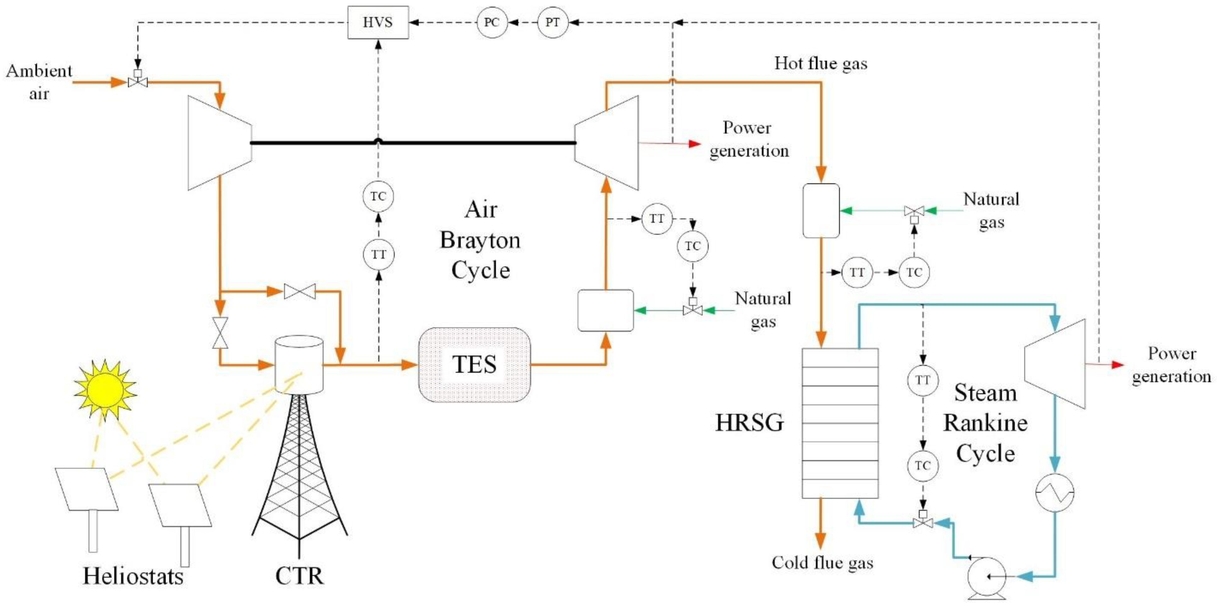
The hybrid solar-combined cycle plant has a capacity of roughly 200 MW between Brayton and Rankine cycles. Three configurations for plant operation are presented here (Figure 1, Figure 2 and Figure 3). The control scheme shown in Figure 1 is used as a basis for the plant. Ambient air is compressed and passed along to a central tower receiver (CTR) where a heliostat field directs concentrated sunlight to heat flowing air during hours of sunlight. When there is no solar activity, the air bypasses the receiver. Downstream of the collector, air passes through a packed-bed storage system. Then, the air passes through a combustion chamber and the hot flue gas is then directed to a gas turbine to produce power. The turbine firing temperature is controlled continuously by manipulating the natural gas flow into the combustion chamber. The net power of the plant is controlled by manipulating the inlet guide vane (IGV) angle of the compressor, which dictates air flow through the system on a volumetric basis. The IGV angle also controls the exit temperature of the CTR. Because the IGV controls both the receiver exit temperature and net power, a high-value selector (HVS) control is employed. The HVS continuously selects the highest IGV angle input between the power and CTR temperature control loops. The primary objective of the HVS controller is to maintain the power setpoint but it can override that setpoint, so collector temperature does not exceed design values.
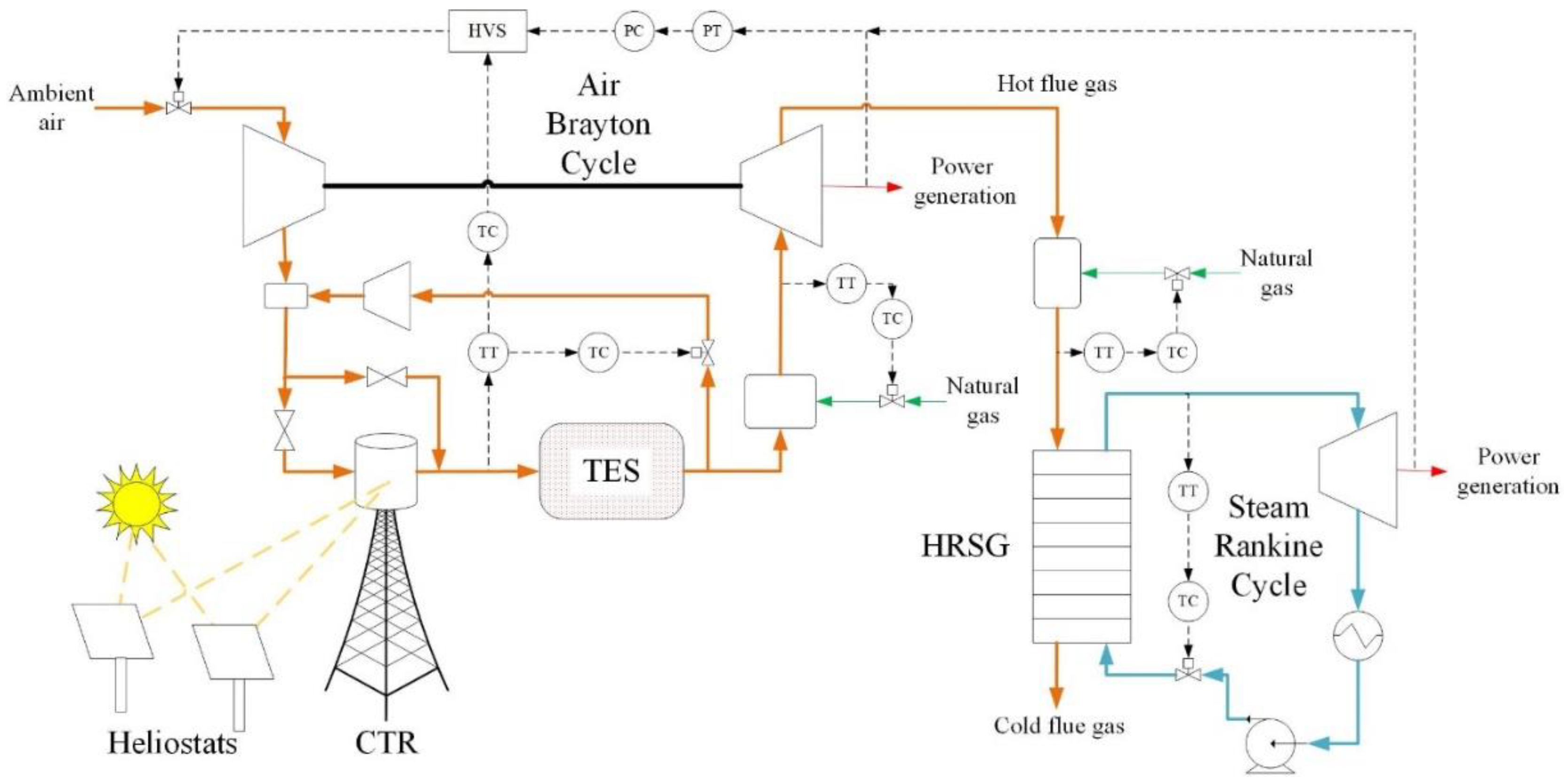
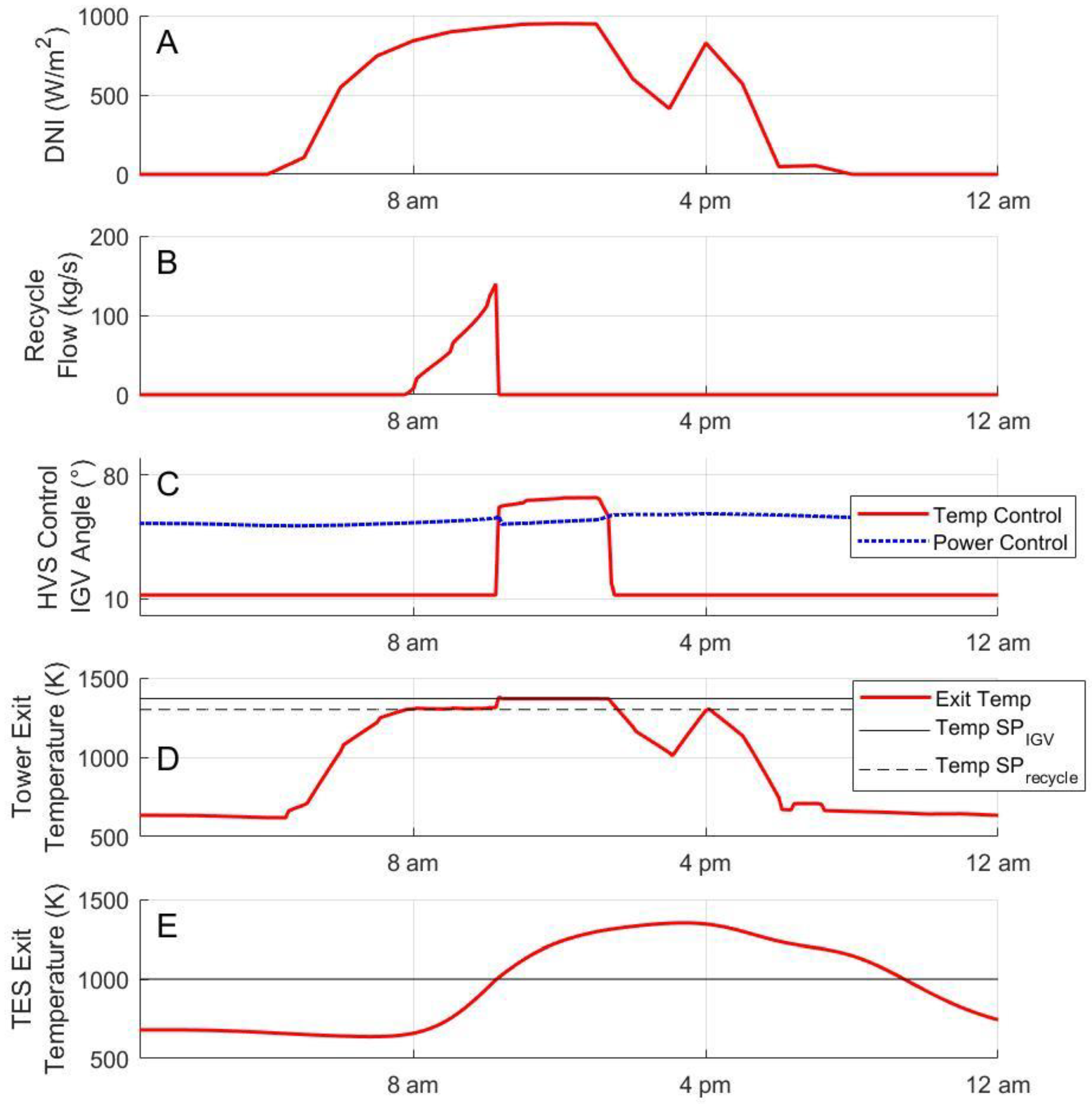
The operation of the base-case plant allows for some flexibility in plant operation, but at some point, the amount of solar energy input exceeds the thermal capacity of the air heat transfer fluid. This results in off-design temperatures within the receiver even with the HVS override. To mitigate this and to harness the excess solar energy utilizing the physical sinks in the system, a recycling configuration is proposed, as shown in Figure 2. Recycling increases the air flow and thus the thermal capacity of the heat transfer fluid in the receiver. This configuration presents a possible means to control CTR exit temperature as an alternative to redirecting excess solar energy to ambient heat (essentially losing solar energy). This solution to temperature control developed in this study is similar to previous research focusing on temperature control in parabolic trough systems through fluid flow manipulation [40]. Figure 4 shows the dynamics of the HVS-recycle control scheme for the recycling configuration. Initially, as direct normal irradiance (DNI) increases throughout the day (Figure 4A), the recycle stream (Figure 4B) turns on to control the receiver exit temperatures (Figure 4D) by increasing mass flow through the tower. Once the recycling temperature, or storage exit temperature, reaches 1000 K (Figure 4E), the recycle stream turns off. When the recycle loop turns off, the temperature control of the HVS may override the power control (Figure 4C) if the solar energy still available would result in temperatures higher than design conditions. The temperature setpoint of the recycle and HVS control loops, shown in Figure 4D, must be offset so that they do not interfere with one another; that is, the setpoint of the temperature from recycling is lower than the HVS control so that the HVS does not control collector temperature while recycling occurs.
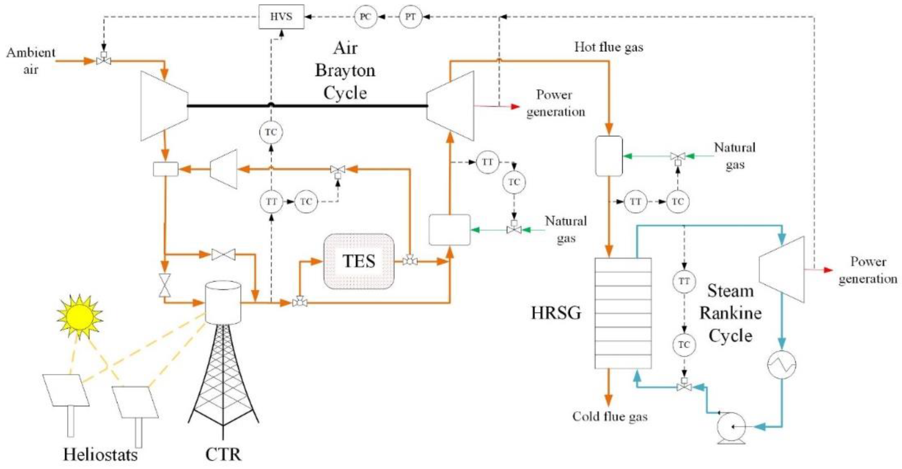
With the increased thermal capacity of the flowing air, an increase in field size or an increase in solar activity results in an increased solar fraction while also maintaining power and temperature of the system. Without a recycle stream, the base-case configuration is not capable of maintaining both power and collector temperature. However, at some point of incrementally increasing field size, the introduced solar energy begins to exceed the thermal capacity of airflow even with the additional recycling capacity. Thus, excessive temperatures are realized in the collector. While there is still substantial solar activity left in the day, the recycle stream is no longer active, as the temperature of the recycle stream has reached its limit of 1000 K. Additionally, as the storage charges, recycle stream steadily increases in temperature at the TES exit, which in turn elevates the temperature entering the tower, making it harder for additional flow to maintain the temperature setpoint. To mitigate the rate at which the recycling temperature rises, a bypass of the TES is implemented in conjunction with recycling. This plant configuration is seen in Figure 3. The bypass operates using on/off control logic tied to the recycle stream:
If the recycle loop is active to keep receiver temperature at 1300 K, the bypass stream is active. The air flow due to IGV angle bypasses the storage and the recycle stream charges the storage.
If the recycle loop is inactive, the bypass stream is inactive as well. The intake air (which represents the total air flow when not recycling) passes through the TES to discharge any stored energy. Otherwise, if there is no stored energy, the storage is bypassed. The recycle loop turns off in one of two ways:
- The temperature of the recycle loop (storage exit temperature) reaches 1000 K. This prevents already heated air from entering the receiver. If this is the case and there is still solar activity which would result in excess temperatures, the HVS operates in temperature control.
- The receiver operates below the 1300 K setpoint and temperature control is not needed.
The bypass allows for only a fraction of the air flow to charge the TES while the recycle stream is active, which results in a lower TES charging rate and rise of TES exit temperature. This results in a longer period that the recycle stream can be active to control temperature and absorb excess solar energy. Without the bypass, the flow from both recycle and inlet charge the TES and the elevated exit temperature is realized far more quickly.
In all plant configurations, the operation of the bottoming steam cycle is identical: the steam cycle operates by controlling the temperature of the steam leaving the heat recovery steam generator (HRSG). The power from the Rankine cycle is not directly controlled but is estimated from the flow needed to maintain a temperature setpoint of steam at the HRSG outlet. Prior to the steam cycle, the flue gas undergoes auxiliary firing to reach an operating temperature of 820 K [41].
To observe the benefits of TES within the system and to more realistically represent variable grid demand where the load is higher during evenings, a peaking power operation is proposed and used as a basis for this study. Under this schedule, the power is set at 100 MW from 11 p.m. to 11 a.m. At 11 a.m., the on-peak power setpoint is set at 175 MW for the next 12 h. The 175 MW is not quite at capacity so that there is room for the IGV angle to increase and control temperature control if needed.
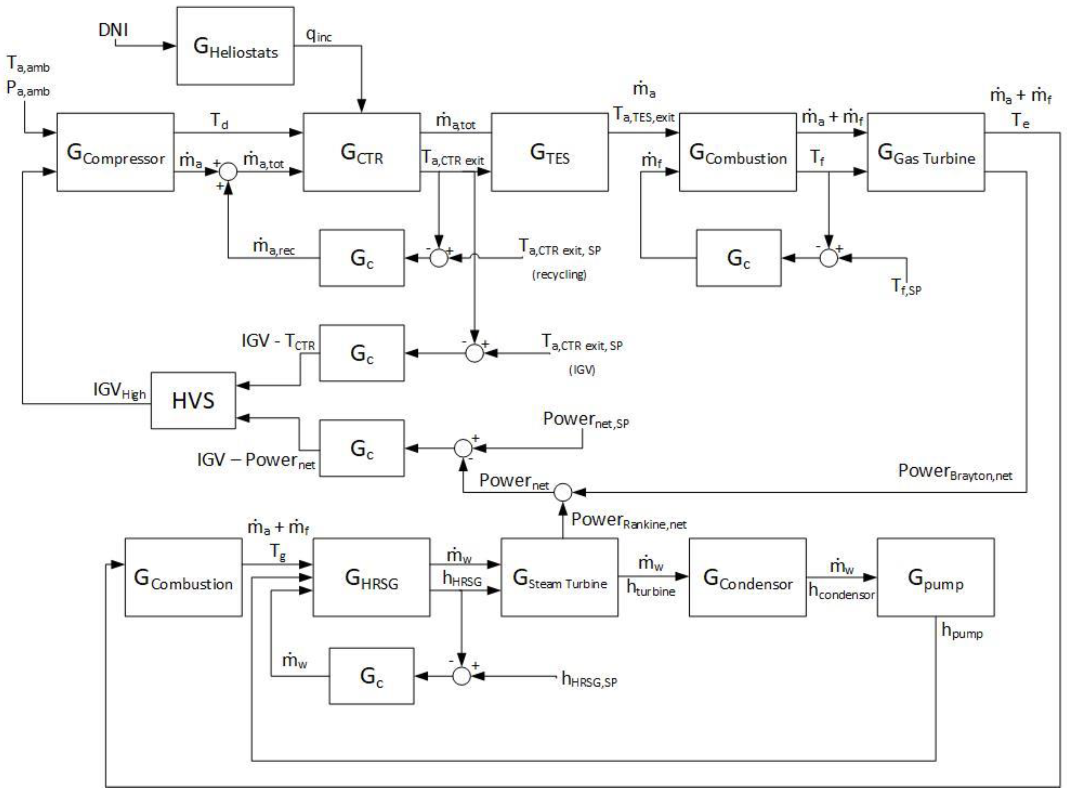
For the recycling configuration, a block diagram of the power plant is seen in Figure 5. This diagram shows the feedback control loops implemented in the recycling plant and is meant to show the flow of information within the control algorithm. The diagram omits the receiver and TES bypass streams for simplicity purposes.
3. Modeling and Methodology
The hybrid plant model is developed in Simulink using first principles [42,43,44,45]. This section presents a general overview of the plant model.
3.1. Gas Turbine Components
The models of the Brayton cycle components are assumed to be relatively fast compared to the transient solar components and steady-state, thermodynamic models are used for Brayton cycle components. These gas turbine components are:
3.1.1. Compressor
The compressor model simulates the inlet air flow rate and compressor exit temperature:
where is the mass flow rate of air dictated by the IGV angle , is the compressor exit temperature, is the compressor inlet temperature or ambient temperature, is the compressor efficiency, is the compression ratio, is the nominal intake air flow rate, and is the cold end ratio specific heats. is the atmospheric pressure, is the reference ambient pressure, is the reference ambient temperature, is the minimum IGV angle, and is the maximum IGV angle.
3.1.2. Combustion Chamber
The exit temperature of the combustion chamber or the turbine firing temperature, , is calculated from the following equation:
where is the efficiency of combustion, is the lower heating value of natural gas, is the specific heat of the exhaust gas flow, and is the fuel (natural gas) flow rate.
where is the compression ratio of the turbine, is the turbine efficiency, is the nominal fuel flow, and is the hot end ratio of the specific heats. From the gas turbine, the hot flue gas is used to power a steam cycle [44].
3.2. Central Tower Receiver
Upstream from the natural gas firing, the CTR heats the compressed air. The tubular gas receiver model consists of energy balances to simulate temperature profiles of flowing air, carrier pipes (tubes), and glass casing, which vacuum-seals the fluid pipes from atmospheric conditions. Dynamic energy models are presented for the three components using control volume energy balances, considering convective and radiative heat transfer. The models assume uniform radial temperature profiles and neglect conductive heat transfer. The energy models are discretized to simulate the axial temperature profile along the length of the tower collector system using integrator function blocks within Simulink. The energy models proposed are:
Air (a):
Pipes (p):
Glass case (c):
where represents the change in temperature of flowing air through the discretized shell volume. The terms , , , and are the density, heat capacity, internal flow transfer coefficient between the air and piping, and external heat transfer coefficient between ambient air and the glass casing, respectively. Temperature dependency of these terms is considered. The heat transfer coefficients are estimated from correlations given by [46] under internal turbulent flow regimes and flow over a flat plate (external flow across the receiver panels). Additionally, , , , , represent the shell volume, shell temperature, heat transfer area, time, and axial position in the tube, respectively, while emissivity, transmissivity, and absorptivity for component are represented by , , and . The Stefan-Boltzmann constant is also shown by and is the solar irradiance incident on the receiver, which is simulated using typical meteorological yearly data and a heliostat field model developed in previous work [47].
3.3. Thermal Energy Storage
A thermal energy storage model simulates the temperature of the working fluid air and stone medium:
Air (a):
3.4. Steam Cycle
The HRSG is modeled as a heat exchanger using the Number of Heat Transfer Units (NTU)-effectiveness method [46,49] The NTU-effectiveness method approximates heat transfer based upon the maximum possible heat transfer rate. The maximum heat transfer rate is defined as:
where is the minimum heat capacity rate of the two fluids involved, which are in this case, the hot flue gas and water/steam. is the hot flue gas inlet temperature, is the inlet temperature of saturated water. The minimum heat capacity rate limits the maximum amount of transferable energy between the participating mediums. The heat capacity rate of a species is its mass flow rate multiplied by its heat capacity. Because one of the mediums undergoes a phase change (steam), the heat capacity rate of the single-phase medium (flue gas) limits the heat transfer and so . The energy transferred in the HRSG is found and used to determine the change in temperature of the flue gas and the production rate of steam assuming a constant evaporation enthalpy:
where is the effectiveness, is the water flow rate, is the enthalpy change of water as it converts to steam, is the change in temperature of the flue gas. The effectiveness of the heat exchanger is assumed to be 0.8. The HRSG is assumed to be isobaric and operating at 75 bar on the water side. Using interpolation of steam table data [50], the outlet enthalpy, temperature, and entropy of steam are found at outlet conditions based upon Equation (13).
The turbine and pump were both assumed to be isentropic, and outlet conditions are estimated at the inlet entropy values. Similarly, the outlet conditions of the condenser are found assuming ideal phase change over a constant pressure. The work of the pump and turbine, along with the rejected heat of the condenser are all found using enthalpy energy models similar to the one used in the HRSG model:
The exit enthalpies for each component were approximated based upon the process conditions and simulated using steam table data. The turbine and pump are both assumed isentropic and the outlet conditions, now at different pressures from the inlet, correspond to the inlet entropy conditions. The condenser, like the HRSG, is isobaric and exit enthalpy is found assuming constant pressure from inlet conditions.
3.5. System Power
The net power generated is the combined net power from the air-gas turbine and steam turbine where compression work is accounted for:
Depending on the system configuration, the net power will change. For the base-case plant seen in Figure 1, the net power is:
For the systems utilizing a recycle stream, the recycle compressor needs to be accounted for in net power production:
where is the heat capacity of the turbine exhaust gas [43].
3.6. System Performance Parameters
To evaluate the performance of each configuration, certain metrics are defined. The overall plant efficiency is defined as the net energy produced relative to the available energy from both solar and natural gas. The available solar energy is based upon the field collector area () and direct normal irradiance. The available natural gas energy is based upon the mass flow and the of natural gas. The overall efficiency is:
The solar performance is evaluated using the solar fraction () and The solar fraction is the amount of generated energy that comes directly from solar energy utilization:
is the marginal energy production from solar relative to the total available solar energy and is calculated using:
4. Results and Discussions
The results are presented as follows. First, the performance of the recycle configuration is compared to that of the base-case configuration. The advantages of recycling are shown by highlighting robust control and improved solar energy utilization. Second, the introduction of a TES bypass with recycling is shown to further improve solar energy utilization without losing system control. Third, the scheme with bypass and recycle streams is further tested using a peaking power load. Lastly, an economic analysis is presented to show the improved levelized cost due to the final plant configuration. For all plots showing system dynamics, the day of June 24th was decided upon as it represents a day with substantial and dynamic solar activity for the location of Las Vegas [51].
4.1. Recycle vs. Base-Sase
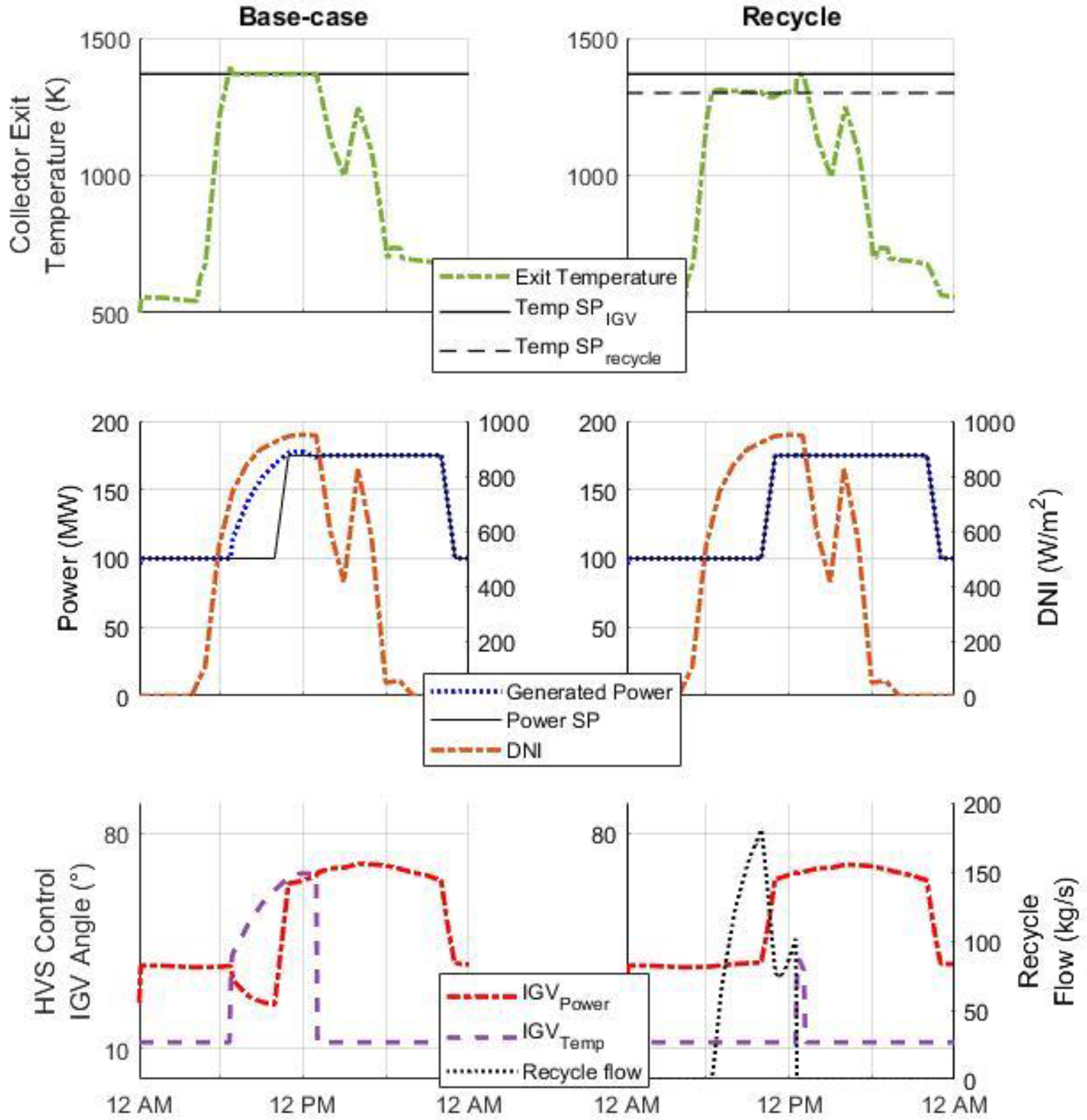
A major goal for this work is to develop an operation scheme with the associated control loops to maximize the solar fraction of the plant. This is achieved by employing systems-level control to reliably dispatch energy through hybridization and storage integration. As mentioned, previous work in the literature has focused on mirror orientation to maintain collector temperatures but through manipulation of air flow and leveraging the packed-bed TES, excess solar energy can be harnessed without having to direct solar energy away from the collector. The obvious means to increase solar fraction is to increase the heliostat field size and storage in accordance with the field. However, under the base-case configuration seen in Figure 1, during days of high solar activity, excess temperatures are sometimes realized even with the HVS override. In other words, the thermal capacity of the heat transfer fluid has been saturated relative to the amount of solar energy available, and the operating temperature exceeds the design specification. Figure 6 compares the dynamics of the base-case and the recycling configurations with respect to net power and temperature control. The plot also shows the manipulated variables for each control scheme and solar activity as a reference. As observed from Figure 6, the base-case configuration is able to maintain the temperature of the air leaving the tower using the HVS controller. However, because the IGV angle must increase to mitigate excessive temperatures during times of high solar activity, the power control is overridden, and the net power output increases accordingly, not allowing the plant to maintain power control.
Air recycling enables independent control of the collector exit temperature and net power production, so long as recycling is viable. Recycling is an option so long as the TES exit temperature is lower than designated recycling threshold. This decoupling of control mitigates excessive temperatures within the tower collector without losing robust power control, as can also be seen in Figure 6. Without recycling, the HVS control would otherwise have to override power control. This improved control enhances solar energy utilization and offers flexibility to increase collector field size to improve solar fraction.
Table 1 shows the yearly performance comparison of the base-case to the recycling configuration. Both plants follow the proposed peaking schedule, utilize a heliostat field size at 550,000 m2 and contain a TES sized at 5700 m3 or roughly 6 h [31]. Use of the recycle results in a slight decrease in overall plant efficiency and STE when compared to the base-case plant which is likely due to an increase in receiver inlet temperature during active solar hours. The increase in inlet temperature results in larger fractional thermal losses due to radiation. However, the recycle-loop plant does perform better in terms of the solar fraction. Because the base-case plant must further open IGV’s to maintain receiver temperature, the total amount of energy (from both solar and gas) produced is larger than the total energy produced from the recycle-controlled plant, despite the same input of solar energy. Therefore, it is logical that the recycling configuration exhibits a larger solar fraction compared to the base-case as the solar input is identical for both plants. This finding further highlights the ability to continuous control plant power when recycling without having to go off setpoint to maintain collector temperatures.
4.2. Recycle + Bypass vs. Recycle Only
Even with a recycle stream, attempting to increase solar fraction by increasing field size has limitations in plant performance similar to the base-case plant. As the storage charges, the increasing storage exit temperature has a heightened effect on the inlet temperature of the receiver as the recycling temperature increases the temperature entering the receiver. The rising exit temperature requires more flow to be recycled to keep receiver temperatures at design specifications. Therefore, a configuration utilizing a storage bypass in conjunction with the recycle loop (Figure 3) is proposed. Under this configuration, only the recycle flow passes through the TES while recycling is active. This operation means that the storage is charged at a significantly lower rate. The plant utilizing only a recycle loop (Figure 2) charges the storage using both the recycle and the air flow rate from the IGVs. This lower charging rate when bypassing TES translates to mitigation of excessively high recycle temperatures, which allows the recycle stream to be active for a longer time when temperature control is needed. This translates to even greater flexibility to harness excess solar energy while maintaining power control.
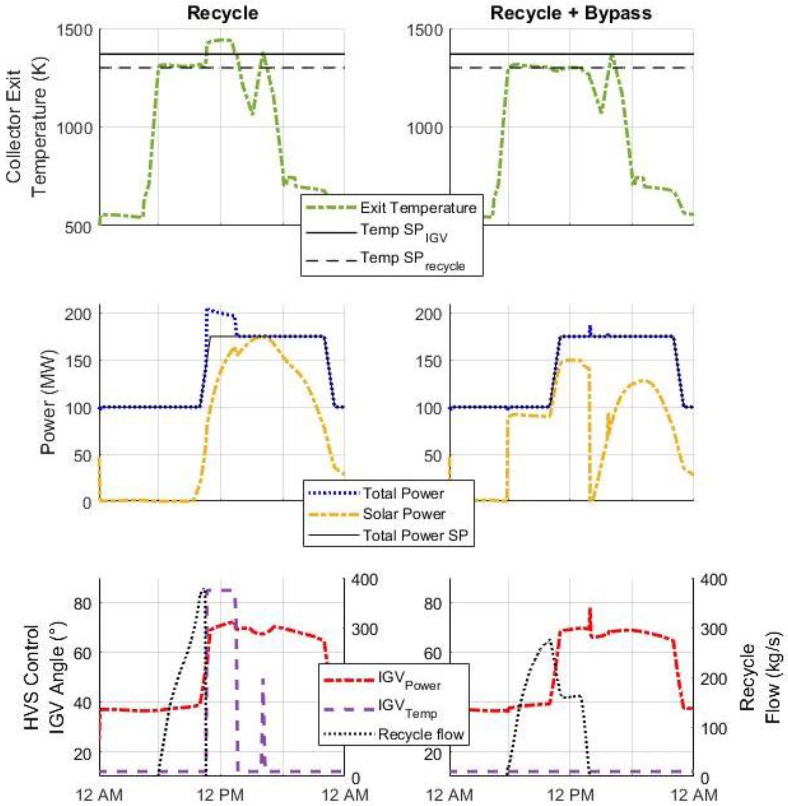
The dynamics of the plant utilizing a fractional bypass are shown in Figure 7 compared to the dynamics of the plant with only a recycle stream. The plots show the dynamics for both plants employing a field sized at 680,000 m2, which is roughly a 24% increase in size from the aforementioned comparison of the base-case vs. recycling configurations. The increase in field size is used in lieu of cases where a significant amount of solar energy is available.
Similar to the base-case plant, the recycle-only configuration struggles to maintain the power setpoint when a larger field is deployed. The storage charges quickly and the HVS selector control overrides the power control of the system in favor of temperature control. However, even at the maximum IGV angle, the thermal capacity of the working fluid is too small for solar energy being introduced to the system. For the bypass system, the slower rate of charging is evident by the longer period that the recycling stream is active. Without bypass, the temperature of the recycle stream rises quickly and forces the recycle stream to shut off under the recycle-only operation. With the bypass, the power setpoint is maintained throughout the day as the HVS control is not needed to control the temperature. Once the recycle/bypass control is turned off, the total air flow (inlet) of the plant passes through the storage, charging the storage if there is still a positive difference between the receiver and storage temperature, and finally discharging the storage once inlet temperatures are lower than storage temperatures.
As can be seen in Figure 7, the solar power produced occurs in two distinct phases when the storage bypass is employed. The first phase follows a pattern similar to the overall power production. During this time, a fraction of the absorbed solar energy, which is due to recycling flow, is dispatched to storage for later use. The remainder (due to IGV) is dispatched directly to the combustion chamber and turbine, which results in a similar pattern as the overall power production. The storage discharging cycle can be examined during the second phase of solar power production, starting around 2 pm. Prior to the second phase, a dip in solar production occurs, which is a result of the temperature gradient in the storage and the time needed for the elevated temperatures at the beginning of the storage to propagate through the bed via advection. Ideally, a hybrid plant would need to be developed so that it can eventually operate primarily through solar usage and continually maintain power without seeing dips in solar production as seen here. The dip in temperature additionally showcases the importance of having hybridized fuel usage so that design temperatures can be maintained while delayed dispatch from the storage is limiting the temperature profile downstream from TES. It exemplifies the reliability seen in a hybrid plant that can dispatch energy quickly when necessary. Furthermore, having to deal with energy propagation through the packed-bed storage poses a potential issue for a plant to operate with consistent solar energy production. This phenomenon gives an opportunity to investigate possible apply advanced control methods to overcome this advective delay that can cause the dip in solar energy generation. Otherwise, a switching system is needed where the directional flow of charging and discharging is opposite, which has been presented by [6]. However, having a switching method would need additional equipment resulting in increased capital cost. Approaching this dip from a process control perspective may allow for consistent operation while mitigating some of the cost of equipment and storage design.
Table 2 shows the yearly performance comparison of the plant operating via recycle and bypass versus operation under recycle-only. Interestingly, the plant using a bypass operates at a slightly lower overall efficiency, while maintaining STE. This is explained by the increased solar fraction that the bypass system exhibits. Within hybrid CSP systems, there exists a tradeoff between solar fraction and overall efficiency. As solar fraction increases, the overall efficiency decreases [52], and findings here further exemplify that tradeoff. However, despite a dip in overall efficiency, the STE of the configuration with both recycle and bypass is similar to the recycle-only plant. Overall, the addition of storage bypass allows for substantial improvements in solar harnessing with respect to the solar fraction. While the use of only a recycle stream to control receiver temperature is valid, utilization of a bypass stream represents an additional means for flexible plant operation while maintaining power load.
4.3. Solar Fraction Enhancement
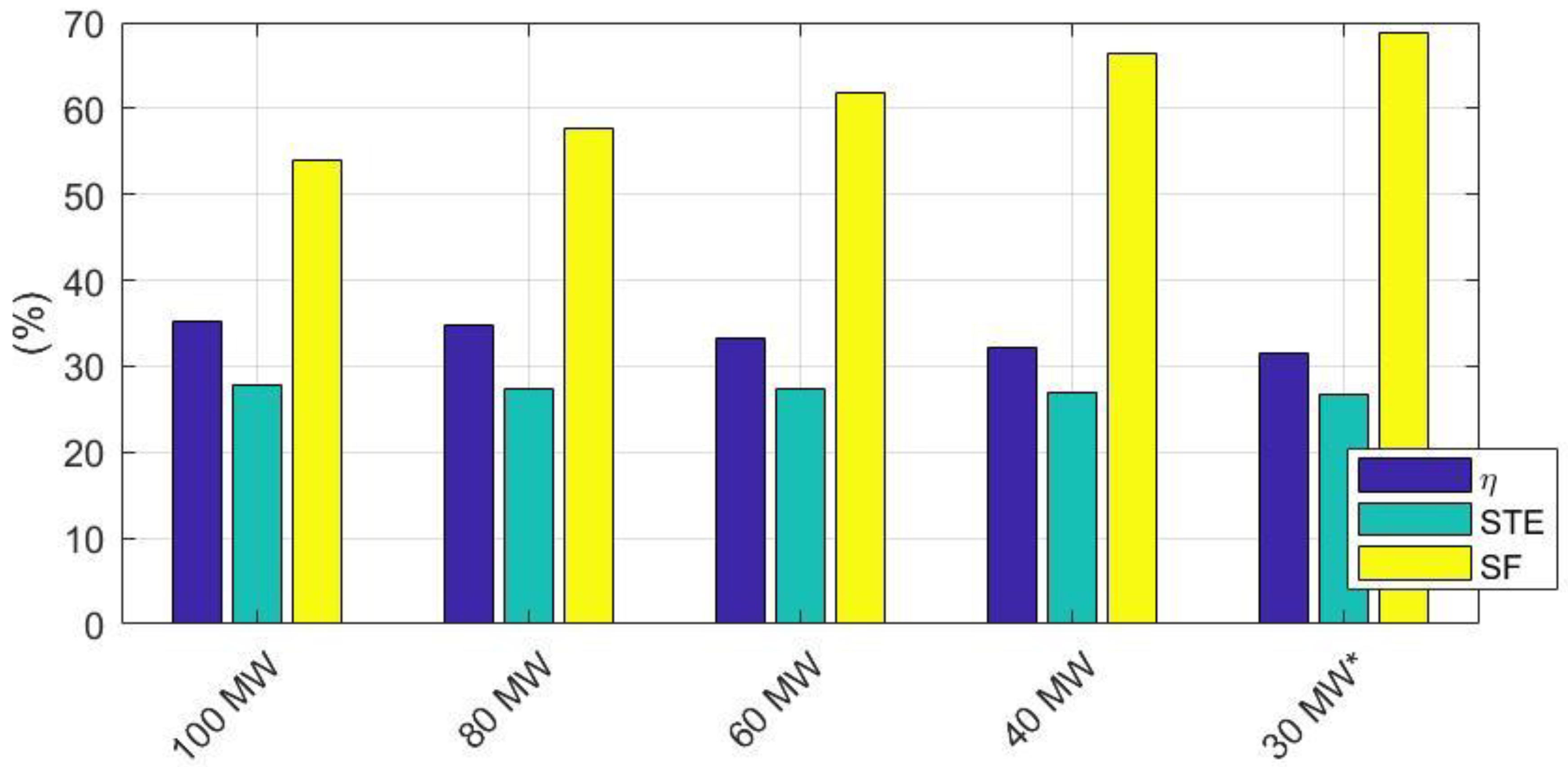
More drastic peaking schedules are also tested to potentially observe very high solar fractions. These scenarios are carried out via a parametric study at incrementally lower power sets point during non-peak hours following the peaking schedule, as previously mentioned. Initially, simulations ran with a field sized at 680,000 m2 and a 6-h TES. This size of field and storage corresponds to the same size of the components studied in Section 4.2. The off-peak power setpoint is decreased incrementally with values beginning at 100 MW and simulations are run at each of those power schedules for the day of June 24th. Lowering of the off-peak setpoint is continued until the plant was unable to maintain the power load due to the HVS-control scheme favoring temperature control over power. The plant performances are summarized in Figure 8.
As seen in Figure 8, lowering the power setpoint during non-peak hours can significantly improve the solar fraction of the plant. Here, the plant exhibits a daily solar fraction greater than 65% when power is ramped down to 40 MW during non-peak hours. At a lower setpoint of 30 MW, the system could not maintain power setpoints and the HVS override was initiated. The setpoint of 30 MW is about as low as possible for modern-day power systems, which have been developed to operate at as low as 15% of capacity [53]. The results of that simulation still show a solar fraction approaching 70%, but at the expense of power control.
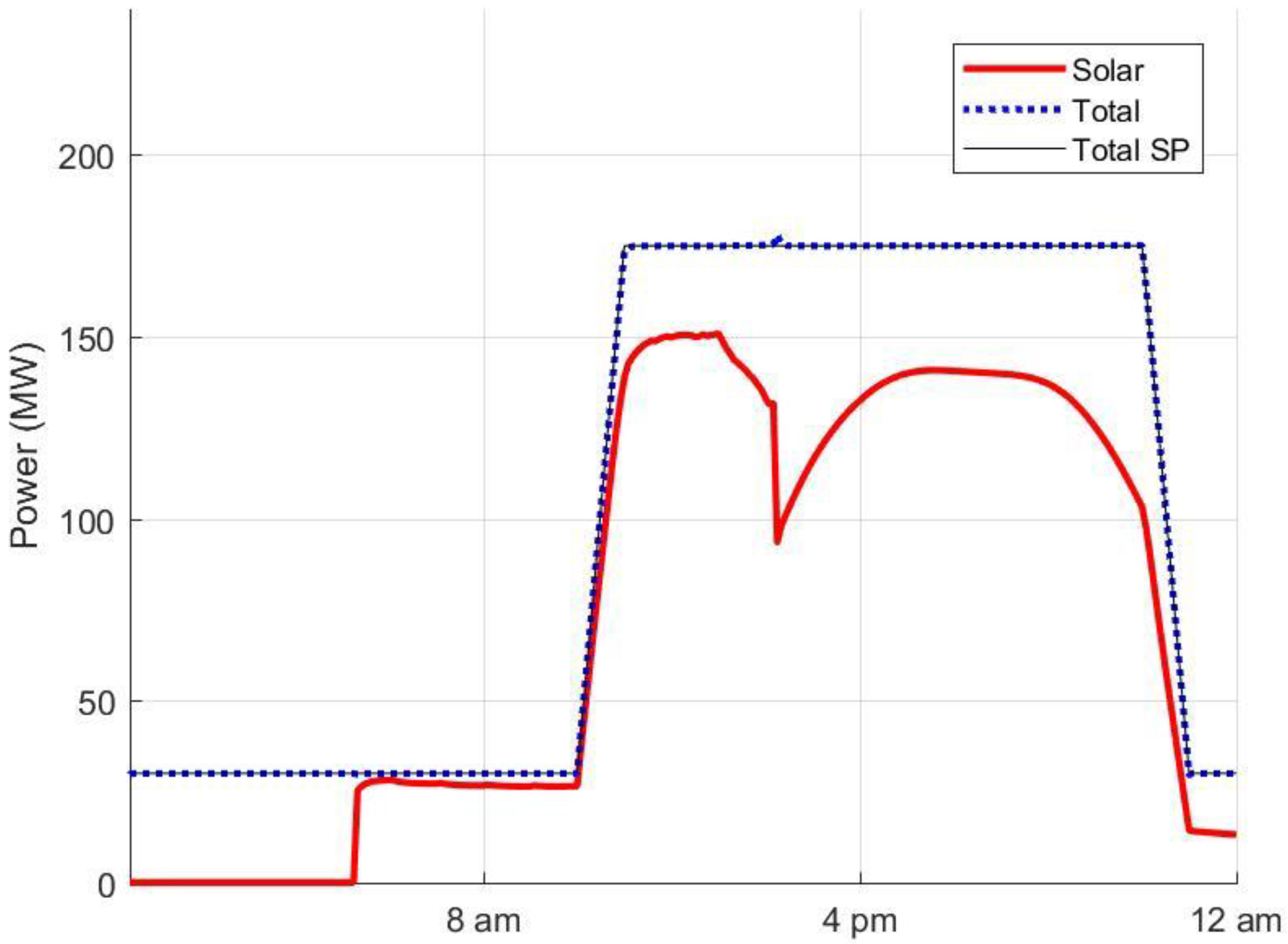
Further tests are carried out by adjusting the size of the storage and the field size to improve solar fraction while maintaining a power schedule with 30 MW as the off-peak setpoint. The tests follow a trial and error method where the TES and field are altered in size and the plant is tested in its ability to maintain power while achieving high solar fraction. This procedure is carried out until a solar fraction of 70% or more was realized with robust power control. First, the storage is increased in size to 8 h. This first test results in an operation that could maintain the drastic peaking schedule with the 30 MW setpoint and exhibits a solar fraction of 68%, slightly below the designated target. The field size is then increased to 740,000 m2. This configuration results in a solar fraction of approximately 71%, while maintaining power control. The power production of June 24th can be seen in Figure 9 for a plant with a field size of 740,000 m2 and 8-h storage. As can be seen, the marginal solar production of the plant is high when a drastic peaking schedule is implemented with TES large enough to handle excess solar energy from the larger collection field. Additionally, by increasing storage size, issues with stored energy dispatch appear to be alleviated somewhat, as can be seen by the less drastic dip between solar power production phases, which is likely due to longer periods of recycling at larger field sizes. At larger field sizes, the increased time of high incidence on the receiver results in recycling being active for a longer duration in the day. Thus, more time is used to charge the TES, which results in an increased exit temperature of the storage but one that remains under the maximum allowable recycling temperature. At smaller field sizes, the recycling does not occur as long, and that shorter time of charging cannot elevate the storage exit temperature.
4.4. Economic Evaluation of Recycling + Bypass Configuration
For the final plant configuration (recycle + bypass), an economic analysis gives insight to its viability compared to the base-case plant. To compare the two plants, the levelized cost of electricity (LCOE) is found following the peaking power schedule between 100 MW and 175 MW. The levelized cost of a power plant is the total cost over the plant’s lifetime relative to the total amount of energy produced over that lifetime. When considering the yearly capital cost and yearly operating cost , the LCOE of a plant is:
where is the year, is the lifetime for the plant, is the discount rate for the plant over its lifetime and is the yearly energy production for year . The yearly capital cost is found by converting the net present value of the total capital cost to annuity. Cost inflation is considered to estimate equipment costs for the year 2018 and for future yearly operation costs. The assumed parameters of the economic analysis are summarized in Table 3.
NREL’s (National Renewable Emery Laboratory) cost model is used to estimate the cost of the plants’ solar equipment, land, and general operation [54]. For any additional information needed, costs for the packed-bed TES and combined cycle equipment are approximated from literature [56,57]. A summary of capital and operating costs can be seen in Table 4 with the calculated LCOE for the base-case and recycle + bypass power plants.
The base-case and recycle + bypass plants exhibit a LCOE of $172.9/MWh and $165.0/MWh respectively, or roughly 4.6% reduction from the base-case to the recycle + bypass configuration. Despite having a larger field in the final configuration which leads to increased capital costs, that configuration is able to generate a larger portion of energy from solar activity. This higher solar fraction results in a reduction in natural gas usage and by extension reduced operation cost relative to the base-case plant. As a reference, the United States’ Energy Information Administration (EIA) reports that as of 2018 the estimated LCOE for solar thermal plants is $165.1/MWh prior to tax credit [58]. This reported LCOE should be noted for solar thermal plants exhibiting an average capacity factor around 25%. For the plant presented, the capacity of the power plant is approximately 68.8% based upon the peaking schedule and 200 MW overall capacity. The capacity of reported solar-only CSP plants is restricted due to the limited amount of available solar energy and storage size. The hybrid plant proposed herein is able to leverage the hybrid operation to enhance the capacity and result in an LCOE similar to current CSP systems. Further LCOE reduction could be achieved by operating the plant at baseload throughout its lifetime, but high solar fractions would be sacrificed. Reduction of capital cost represents the major challenge in reducing the LCOE of CSP systems, with solar components representing 42% of overall capital cost for the final plant configuration. Cost reduction of these components may result in hybrid solar-combined cycle power plants being competitive with other power generation systems. However, the study presented herein shows that, through holistic design and operation, the LCOE of a hybrid CSP plant can be reduced for plants exhibiting very large solar fractions.
5. Conclusions
Investigation of a CSP-hybrid plant design and operation is undertaken to achieve very high solar fractions. A first-principles model of a tower-driven CSP hybridized with a combined cycle power plant is developed in Matlab/Simulink. The hybrid plant contains packed-bed thermal energy storage. The study presents a systematic approach where modifications are made to the configuration of the plant and the performance of each configuration is discussed in depth. Such an approach to achieve a high solar fraction has not been applied in CSP literature. Proposed plant configurations operate using a novel recycling configuration to control receiver exit temperature. Receiver exit temperature and power control are system performance metrics of particular interest. A base-case plant is shown to maintain power control and mitigation of temperatures at smaller field sizes. In cases with excessive solar energy available, represented here by increasing the field size in lieu of increased solar irradiance, the base-case cannot maintain a power setpoint, as the HVS-override must increase flow to maintain receiver temperature. The recycling operation is implemented to control temperature independently, resulting in greater reliability in power control. Additional flexibility observed in the proposed recycle scheme results in a yearly solar fraction over 30% when employing a peaking power load. This results in a 4.9% improvement in solar fraction relative to the base-case plant. At subsequently larger field sizes, the recycle control faces issues with inability to simultaneously control collector exit temperature and net power. Therefore, a bypass of storage is implemented to reduce storage charging rate and allow for longer recycle times. Introduction of a bypass allows for flexibility to install larger heliostat fields, which results in a higher solar fraction, tight control, and improved solar-to-electric efficiency. The system utilizing a bypass exhibits a 6% improvement in solar fraction when compared to the plant lacking a TES bypass. By implementing a drastic peaking power load schedule, solar fractions as high as 70% are realized for the final plant configuration. Lastly, an economic analysis shows that by implementing a recycling and TES bypass operation, the LCOE of such a power plant can be reduced by over 4% despite an increase in overall capital cost of the plant. To improve LCOE, further reduction of capital cost is necessary, specifically the capital cost of solar collection equipment. Operation of the plant at baseload can also lead to further reduced LCOE for the hybrid plant.
Author Contributions
Conceptualization, K.E. and K.P.; Methodology, K.E., K.R., and K.P.; Software, K.E. and K.P.; Validation, K.E. and K.P.; Formal Analysis, K.E., S.M.S., and K.R.; Investigation, K.E.; Resources, K.P.; Data Curation, K.E. and K.R.; Writing-Original Draft Preparation, K.E.; Writing-Review & Editing, K.E., S.M.S., and K.P.; Visualization, K.E., S.M.S., and K.P.; Supervision, K.P.; Project Administration, K.P.; Funding Acquisition, K.P.
Funding
This work is funded by United States’ Department of Energy (DOE) under the DE-EE0007712 grant, which is affiliated with the DOE Industrial Assessment Center as well as further funding from the University of Utah Chemical Engineering Department.
Conflicts of Interest
The authors declare no conflict of interest.
Nomenclature
| Acronym | Description |
| CSP | Concentrated solar power |
| CTR | Central tower receiver |
| DNI | Direct normal irradiance |
| STE | Solar-to-electric efficiency |
| SF | Solar fraction |
| ISCC | Integrate solar combined cycle |
| IGV | Inlet guide vane |
| NTU | Number of Heat Transfer Units |
| NREL | National Renewable Energy Laboratory |
| PTC | Parabolic trough collector |
| APC | Advanced process control |
| TES | Thermal energy storage |
| HVS | High-value selector |
| HRSG | Heat recovery steam generator |
| LCOE | Levelized cost of electricity |
| Symbol | Description | Value | Units |
| Nominal baseload air flow rate | 537 | kg/s | |
| Air-flow rate | - | kg/s | |
| Nominal baseload fuel flow rate | 10.2 | kg/s | |
| Fuel flow rate | - | kg/s | |
| Internal air flow heat transfer coefficient for CTR | - | kW/m2·K | |
| External air flow heat transfer coefficient for CTR | - | kW/m2·K | |
| Internal air flow heat transfer coefficient for TES | - | kW/m2·K | |
| Heat transfer area glass | 300 | m2 | |
| Heat transfer area receiver pipe (per pipe) | 3.73 | m2 | |
| Heat transfer area of the stone medium in TES | - | m2 | |
| Ambient atmospheric reference pressure | 1 | atm | |
| Ambient atmospheric pressure | - | atm | |
| Temperature of air | - | K | |
| Ambient atmospheric reference temperature | 288.15 | K | |
| Ambient atmospheric temperature | - | K | |
| Temperature of receiver glass | - | K | |
| Compressor outlet temperature | - | K | |
| Turbine exhaust temperature | - | K | |
| Turbine firing temperature setpoint | 1396 | K | |
| Temperature change of flue gas in HRSG | - | K | |
| Temperature of receiver pipe | - | K | |
| Shell volume of flowing air | - | m3 | |
| Shell volume of receiver glass | - | m3 | |
| Shell volume of receiver pipe | - | m3 | |
| Specific heat of combustion exhaust gas | 1.157 | kJ/kg·K | |
| Heat capacity of air | - | kJ/kg·K | |
| Heat capacity of receiver glass | 840 | kJ/kg·K | |
| Heat capacity of receiver pipe | 0.574 | kJ/kg·K | |
| Heat capacity of TES | - | kJ/kg·K | |
| Incident concentrated solar irradiance | - | kW/m2 | |
| Hot end ratio of specific heats | 1.33 | - | |
| Cold end ratio of specific heats | 1.4 | - | |
| Emissivity of receiver glass | 0.9 | - | |
| Emissivity of receiver pipe | 0.25 | - | |
| Compressor efficiency | 86 | % | |
| Combustion efficiency | 99 | % | |
| Nominal fuel to electric efficiency | - | % | |
| Overall plant efficiency | - | % | |
| IGV angle | - | ° | |
| Maximum IGV angle | 85.0 | ° | |
| Minimum IGV angle | 11.6 | ° | |
| Absorptivity of receiver pipe | 0.97 | - | |
| Density of air | - | kg/m3 | |
| Density of receiver glass | 2400 | kg/m3 | |
| Density of receiver pipe | 7850 | kg/m3 | |
| Density of TES medium | 1933 | kg/m3 | |
| Transmissivity of receiver glass | 0.96 | - | |
| Lower heating value of fuel | 46,000 | kJ/kg | |
| Compression ratio of compressor | 15.4 | - | |
| Compression ratio of turbine | 15.4 | - | |
| Solar fraction | - | % | |
| Solar-to-electric efficiency | - | % | |
| Stefan-Boltzmann constant | 5.67 × 10⁻⁸ | W/m2·K4 | |
| Effectiveness of HRSG | 0.80 | - | |
| Minimum heat capacity rate | - | kW/K | |
| Temperature drop of flue gas of HRSG | - | K | |
| Enthalpy change of steam/water across unit j | - | kJ/kg | |
| Flow rate of steam/water | - | kg/s | |
| Heat rate of component i (HRSG or condenser) | - | kW | |
| Work of component i (steam turbine or pump) | - | kW | |
| Net plant power production | - | MW | |
| Heliostat field total incident area | - | m2 |
References
- Zhang, H.L.; Baeyens, J.; Eve, J.D.; Eres, G.C. Concentrated solar power plants: Review and design methodology. Renew. Sustain. Energy Rev. 2013, 22, 466–481. [Google Scholar] [CrossRef]
- Kuravi, S.; Trahan, J.; Goswami, D.Y.; Rahman, M.M.; Stefanakos, E.K. Thermal energy storage technologies and systems for concentrating solar power plants. Prog. Energy Combust. Sci. 2013, 39, 285–319. [Google Scholar] [CrossRef]
- Madaeni, S.H.; Member, S.; Sioshansi, R.; Denholm, P. How Thermal Energy Storage Enhances the Economic Viability of Concentrating Solar Power. Proc. IEEE 2012, 10, 335–347. [Google Scholar] [CrossRef]
- Singh, H.; Saini, R.P.; Saini, J.S. A review on packed bed solar energy storage systems. Renew. Sustain. Energy Rev. 2010, 14, 1059–1069. [Google Scholar] [CrossRef]
- Grange, B.; Dalet, C.; Falcoz, Q.; Siros, F.; Ferrière, A. Simulation of a Hybrid Solar Gas-turbine Cycle with Storage Integration. Energy Procedia 2014, 49, 1147–1156. [Google Scholar] [CrossRef]
- Grange, B.; Dalet, C.; Falcoz, Q.; Ferriere, A.; Flamant, G. Impact of thermal energy storage integration on the performance of a hybrid solar gas-turbine power plant. Appl. Therm. Eng. 2016, 105, 266–275. [Google Scholar] [CrossRef]
- Kalogirou, S. Solar Energy Engineering Processes and Systems; Academic Press: Cambridge, MA, USA, 2009. [Google Scholar]
- Powell, K.M.; Edgar, T.F. Modeling and control of a solar thermal power plant with thermal energy storage. Chem. Eng. Sci. 2012, 71, 138–145. [Google Scholar] [CrossRef]
- Alva, G.; Lin, Y.; Fang, G. An overview of thermal energy storage systems. Energy 2018, 144, 341–378. [Google Scholar] [CrossRef]
- Barlev, D.; Vidu, R.; Stroeve, P. Innovation in concentrated solar power. Sol. Energy Mater. Sol. Cells 2011, 95, 2703–2725. [Google Scholar] [CrossRef]
- Pelay, U.; Luo, L.; Fan, Y.; Stitou, D.; Rood, M. Thermal energy storage systems for concentrated solar power plants. Renew. Sustain. Energy Rev. 2017, 79, 82–100. [Google Scholar] [CrossRef]
- Johnson, E.; Bates, L.; Dower, A.; Bueno, P.C.; Anderson, R. Thermal energy storage with supercritical carbon dioxide in a packed bed: Modeling charge-discharge cycles. J. Supercrit. Fluids 2018, 137, 57–65. [Google Scholar] [CrossRef]
- Klein, P.; Roos, T.; Sheer, T. Parametric analysis of a high temperature packed bed thermal storage design for a solar gas turbine. Sol. Energy 2015, 118, 59–73. [Google Scholar] [CrossRef]
- Tian, Y.; Zhao, C.Y. A review of solar collectors and thermal energy storage in solar thermal applications. Appl. Energy 2013, 104, 538–553. [Google Scholar] [CrossRef] [Green Version]
- Ju, X.; Wei, G.; Du, X.; Yang, Y. A novel hybrid storage system integrating a packed-bed thermocline tank and a two-tank storage system for concentrating solar power (CSP) plants. Appl. Therm. Eng. 2016, 92, 24–31. [Google Scholar] [CrossRef]
- Barigozzi, G.; Bonetti, G.; Franchini, G.; Perdichizzi, A.; Ravelli, S. Thermal performance prediction of a solar hybrid gas turbine. Sol. Energy 2012, 86, 2116–2127. [Google Scholar] [CrossRef]
- Peterseim, J.H.; Tadros, A.; White, S.; Hellwig, U.; Landler, J.; Galang, K. Solar Tower-biomass Hybrid Plants—Maximizing Plant Performance. Energy Procedia 2014, 49, 1197–1206. [Google Scholar] [CrossRef]
- Santos, M.J.; Merchán, R.P.; Medina, A.; Hernández, A.C. Seasonal thermodynamic prediction of the performance of a hybrid solar gas-turbine power plant. Energy Convers. Manag. 2016, 115, 89–102. [Google Scholar] [CrossRef]
- Powell, K.M.; Rashid, K.; Ellingwood, K.; Tuttle, J.; Iverson, B.D. Hybrid concentrated solar thermal power systems: A review. Renew. Sustain. Energy Rev. 2017, 80, 215–237. [Google Scholar] [CrossRef]
- Rashid, K.; Safdarnejad, S.M.; Powell, K.M. Dynamic simulation, control, and performance evaluation of a synergistic solar and natural gas hybrid power plant. Energy Convers. Manag. 2019, 179, 270–285. [Google Scholar] [CrossRef]
- Powell, K.; Hedengren, J.; Hedengren, J.D.; Edgar, T.F. Dynamic Optimization of a Solar Thermal Energy Storage System over a 24 Hour Period using Weather Forecasts. In Proceedings of the 2013 American Control Conference, Washington, DC, USA, 17–19 June 2013. [Google Scholar]
- Çengel, Y.A.; Boles, M.A. Thermodynamics: An Engineering Approach; McGraw-Hill Education: New York, NY, USA, 2014. [Google Scholar]
- Bonadies, M.F.; Mohagheghi, M.; Ricklick, M.; Kapat, J.S. Solar retrofit to combined cycle power plant with thermal energy storage. In Proceedings of the ASME Turbo Expo, Glasgow, UK, 14–18 June 2010; pp. 921–931. [Google Scholar]
- Kribus, A.; Zaibel, R.; Carey, D.; Segal, A.; Karni, J. A solar-driven combined cycle power plant. Sol. Energy 1998, 62, 121–129. [Google Scholar] [CrossRef] [Green Version]
- Spelling, J.; Favrat, D.; Martin, A.; Augsburger, G. Thermoeconomic optimization of a combined-cycle solar tower power plant. Energy 2012, 41, 113–120. [Google Scholar] [CrossRef]
- Heller, P.; Pfaender, M.; Denk, T. Test and evaluation of a solar gas turbine system. Sol. Energy 2006, 80, 1225–1230. [Google Scholar] [CrossRef]
- Korzynietz, R.; Brioso, J.A.; Del Río, A.; Quero, M.; Gallas, M.; Uhlig, R.; Ebert, M.; Buck, R.; Teraji, D. Solugas—Comprehensive analysis of the solar hybrid Brayton plant. Sol. Energy 2016, 135, 578–589. [Google Scholar] [CrossRef]
- Quero, M.; Korzynietz, R.; Ebert, M.; Jiménez, A.A.; del Río, A.; Brioso, J.A. Solugas—Operation experience of the first solar hybrid gas turbine system at MW scale. Energy Procedia 2013, 49, 1820–1830. [Google Scholar] [CrossRef]
- Olivenza-León, D.; Medina, A.; Hernández, A.C. Thermodynamic modeling of a hybrid solar gas-turbine power plant. Energy Convers. Manag. 2015, 93, 435–447. [Google Scholar] [CrossRef]
- Behar, O.; Khellaf, A.; Mohammedi, K. A review of studies on central receiver solar thermal power plants. Renew. Sustain. Energy Rev. 2013, 23, 12–39. [Google Scholar] [CrossRef]
- Okoroigwe, E.; Madhlopa, A. An integrated combined cycle system driven by a solar tower: A review. Renew. Sustain. Energy Rev. 2016, 57, 337–350. [Google Scholar] [CrossRef]
- Camacho, E.F.; Gallego, A.J. Optimal operation in solar trough plants: A case study. Sol. Energy 2013, 95, 106–117. [Google Scholar] [CrossRef]
- Pasamontes, M.; Álvarez, J.D.; Guzmán, J.L.; Lemos, J.M.; Berenguel, M. A switching control strategy applied to a solar collector field. Control Eng. Pract. 2011, 19, 135–145. [Google Scholar] [CrossRef]
- Camacho, E.F.; Berenguel, M.; Gallego, A.J. Control of thermal solar energy plants. J. Process Control 2014, 24, 332–340. [Google Scholar] [CrossRef]
- Camacho, E.F.; Gallego, A.J. Model Predictive Control In Solar Trough Plants: A Review. IFAC-PapersOnLine 2015, 48, 278–285. [Google Scholar] [CrossRef]
- Silva, R.N.; Rato, L.M.; Lemos, J.M.; Coito, F. Cascade control of a distributed collector solar field. J. Process Control 1997, 7, 111–117. [Google Scholar] [CrossRef]
- Camacho, E.F.; Berenguel, M.; Alvarado, I.; Limon, D. Control of Solar Power Systems: A survey. IFAC Proc. Vol. 2010, 43, 817–822. [Google Scholar] [CrossRef]
- Camacho, E.F.; Berenguel, M. Control of Solar Energy Systems. IFAC Proc. Vol. 2012, 45, 848–855. [Google Scholar] [CrossRef]
- Powell, K.M.; Edgar, T.F. Control of a large scale solar thermal energy storage system. In Proceedings of the 2011 American Control Conference, San Francisco, CA, USA, 29 June–1 July 2011; pp. 1530–1535. [Google Scholar]
- Juuso, E.K.; Yebra, L.J. Smart adaptive control of a solar collector field. IFAC Proc. Vol. 2014, 47, 2564–2569. [Google Scholar] [CrossRef]
- Valdés, M.; Rapún, J.L. Optimization of heat recovery steam generators for combined cycle gas turbine power plants. Appl. Therm. Eng. 2001, 21, 1149–1159. [Google Scholar] [CrossRef]
- Beasley, D.E.; Clark, J.A. Transient response of a packed bed for thermal energy storage. Int. J. Heat Mass Transf. 1984, 21, 1659–1669. [Google Scholar] [CrossRef]
- Ellingwood, K.; Tuttle, J.; Powell, K. Leveraging storage and hybridization to maximize renewable utilization. In Proceedings of the AIChE Annual Meeting, San Francisco, CA, USA, 13–18 November 2016. [Google Scholar]
- Kim, J.S.; Powell, K.M.; Edgar, T.F. Nonlinear model predictive control for a heavy-duty gas turbine power plant. In Proceedings of the 2013 American Control Conference, Washington, DC, USA, 17–19 June 2013; pp. 2952–2957. [Google Scholar]
- MathWorks Inc. MATLAB and Statistics Toolbox Release 2017a; MathWorks Inc.: Natick, MA, USA, 2017. [Google Scholar]
- Cengel, Y.; Cimbala, J.; Turner, R. Fundementals of Thermal-Fluid Sciences, 4th ed.; McGraw-Hill: New York, NY, USA, 2012. [Google Scholar]
- Ramsey, J.; Kuehn, T. Appendix D: Solar Radiation. 2018. Available online: http://www.me.umn.edu/courses/me4131/LabManual/AppDSolarRadiation.pdf (accessed on 1 May 2017).
- Wilkes, J.O. Fluid Mechanics for Chemical Engineers, 2nd ed.; Pearson Education, Inc.: London, UK, 2006. [Google Scholar]
- Incropera, F.P.; Dewitt, D.P.; Bergman, T.L.; Lavine, A.S. Fundamentals of Heat and Mass Transfer; John Wiley: Hoboken, NJ, USA, 2007. [Google Scholar]
- Spirax Sarco. Pages—Steam Tables. 2018. Available online: http://www.spiraxsarco.com/Resources/Pages/steam-tables.aspx (accessed on 9 February 2018).
- NREL. NSRDB Update—TMY3: Alphabetical List by State and City. Available online: http://rredc.nrel.gov/solar/old_data/nsrdb/1991-2005/tmy3/by_state_and_city.html (accessed on 10 May 2017).
- Peng, S.; Wang, Z.; Hong, H.; Xu, D.; Jin, H. Exergy evaluation of a typical 330 MW solar-hybrid coal-fired power plant in China. Energy Convers. Manag. 2014, 85, 848–855. [Google Scholar] [CrossRef]
- Ansolda Energia. Innovation Based on Proven Technology; Ansolda Energia: Genova, Italy, 2018. [Google Scholar]
- Turchi, C.S.; Heath, G.A. Molten Salt Power Tower Cost Model for the System Advisor Model (SAM); National Renewable Energy Lab: Golden, CO, USA, 2013. [Google Scholar]
- Mansouri, M.T.; Ahmadi, P.; Kaviri, A.G.; Jaafar, M.N.M. Exergetic and economic evaluation of the effect of HRSG configurations on the performance of combined cycle power plants. Energy Convers. Manag. 2012, 58, 47–58. [Google Scholar] [CrossRef]
- Allen, K.; von Backström, T.; Joubert, E.; Gauché, P. Rock bed thermal storage: Concepts and costs. AIP Conf. Proc. 2016, 1734, 50003. [Google Scholar] [Green Version]
- EIA. Capital Cost Estimates for Utility Scale Electricity Generating Plants; EIA: Washington, DC, USA, 2016. [Google Scholar]
- EIA. Levelized Cost and Levelized Avoided Cost of New Generation Resources in the Annual Energy Outlook 2018; EIA: Washington, DC, USA, 2018. [Google Scholar]
Figure 1.
Schematic of the base-case configuration of the power plant.

Figure 2.
Schematic of the recycling configuration of the power plant.

Figure 3.
Schematic of the recycling with thermal energy storage (TES) bypass configuration of the power plant.
Figure 3.
Schematic of the recycling with thermal energy storage (TES) bypass configuration of the power plant.

Figure 4.
Dynamics of high-value selector (HVS)-recycle control for a plant set at 150 MW load and utilizing only a recycle control (no storage bypass). From top to bottom: (A) direct normal irradiance (DNI) for June 24th; (B) recycle loop flow rate; (C) inlet guide vane (IGV) angle dictated by power/temperature HVS controller; (D) exit temperature of central tower receiver (CTR), (E) storage exit temperature along with 1000 K limit for recycling temperature. SP = setpoint.

Figure 5.
Block diagram of the power plant employing a recycling configuration. The variables of the diagram are described in Nomenclature.
Figure 5.
Block diagram of the power plant employing a recycling configuration. The variables of the diagram are described in Nomenclature.

Figure 6.
Temperature and power control for the base-case and recycling plants for June 24th (SP = setpoint).
Figure 6.
Temperature and power control for the base-case and recycling plants for June 24th (SP = setpoint).

Figure 7.
Comparison of plant control with and without TES bypass for June 24th.

Figure 8.
Summary of the parametric study of sequential decreases in off-peak power setpoint for peaking scenario. * The plant could not maintain power load at a 30 MW lower setpoint.
Figure 8.
Summary of the parametric study of sequential decreases in off-peak power setpoint for peaking scenario. * The plant could not maintain power load at a 30 MW lower setpoint.

Figure 9.
Power production of plant operating with storage bypass, extreme power peaking, and increased storage size to enhance solar fraction. The load is shown for June 24th.
Figure 9.
Power production of plant operating with storage bypass, extreme power peaking, and increased storage size to enhance solar fraction. The load is shown for June 24th.


Table 1.
Yearly performance comparison for the base plant vs. plant with recycle stream.
| Metric | Base-Case (%) | Recycle (%) | Change Relative to Base-Case (%) |
|---|---|---|---|
| 37.8 | 36.3 | −3.9% | |
| 22.4 | 22.2 | −0.8% | |
| 29.9 | 31.4 | +4.9% |
Table 2.
Yearly performance comparison for recycle-only plant vs. recycle plant with bypass.
| Metric | Recycle-Only (%) | Recycle + Bypass (%) | Change Relative to Recycle Only (%) |
|---|---|---|---|
| 36.5 | 35.9 | −1.8 | |
| 23.6 | 23.6 | +0.0 | |
| 36.6 | 39.1 | +6.6 |
Table 3.
Assumptions of the economic analysis.
| Parameter | Value |
|---|---|
| Plant lifetime | 25 years [54] |
| Inflation rate | 4.5% [55] |
| Discount rate | 5.5% [20] |
| Natural gas price | $6/MMBTU [54] |
Table 4.
Economic analysis summary.
| Description | Base-Case | Recycle + Bypass | Basis/Comments |
|---|---|---|---|
| Direct Capital Costs | |||
| Heliostat field | $206,931,600 | $255,824,700 | $180/m2 [54] |
| Tower + receiver | $71,890,300 | $71,890,300 | $105/kWt [54] |
| Packed bed TES | $14,310,200 | $19,080,300 | $10/kWht [56] |
| Combined cycle | $220,800,000 | $220,800,000 | $1104/kW [57] |
| Other Costs | $142,417,200 | $146,174,900 | Site improvements, plant balance, contingency [54] |
| Indirect Capital Costs | |||
| EPC and Owner Cost | $74,350,700 | $80,665,000 | 11% of direct capital costs [54] |
| Land Cost | $19,530,000 | $19,530,000 | $1953 acres at $10,000/acre [54] |
| Yearly Operating Costs | |||
| Natural Gas | $34,441,900 | $28,384,500 | $6/MMBTU |
| Variable Operation | $3,526,700 | $3,526,700 | $4 MWh [54] |
| Fixed Operation | $11,122,200 | $11,122,200 | $51/kW-yr [54] |
| Total Lifetime Cost | $5,206,671,000 | $4,899,579,700 | |
| Yearly Energy Production | 1,204,500 MWh | 1,187,700 MWh | |
| LCOE | $172.9/MWh | $165.0/MWh |
© 2018 by the authors. Licensee MDPI, Basel, Switzerland. This article is an open access article distributed under the terms and conditions of the Creative Commons Attribution (CC BY) license (http://creativecommons.org/licenses/by/4.0/).
Share and Cite
MDPI and ACS Style
Ellingwood, K.; Safdarnejad, S.M.; Rashid, K.; Powell, K. Leveraging Energy Storage in a Solar-Tower and Combined Cycle Hybrid Power Plant. Energies 2019, 12, 40. https://doi.org/10.3390/en12010040
AMA Style
Ellingwood K, Safdarnejad SM, Rashid K, Powell K. Leveraging Energy Storage in a Solar-Tower and Combined Cycle Hybrid Power Plant. Energies. 2019; 12(1):40. https://doi.org/10.3390/en12010040
Chicago/Turabian StyleEllingwood, Kevin, Seyed Mostafa Safdarnejad, Khalid Rashid, and Kody Powell. 2019. "Leveraging Energy Storage in a Solar-Tower and Combined Cycle Hybrid Power Plant" Energies 12, no. 1: 40. https://doi.org/10.3390/en12010040
Note that from the first issue of 2016, this journal uses article numbers instead of page numbers. See further details here.