Influence of the Applied Working Fluid and the Arrangement of the Steering Edges on Multi-Vane Expander Performance in Micro ORC System


Department of Thermodynamics, Theory of Machines and Thermal Systems, Faculty of Mechanical and Power Engineering, Wrocław University of Science and Technology, Wybrzeże Wyspiańskiego 27, Wrocław 50-370, Poland
*
Author to whom correspondence should be addressed.
Energies 2018, 11(4), 892; https://doi.org/10.3390/en11040892
Submission received: 22 March 2018
/
Revised: 30 March 2018
/
Accepted: 10 April 2018
/
Published: 11 April 2018
(This article belongs to the Special Issue Alternative Sources of Energy Modeling and Automation)
Abstract
:Micro-power domestic organic Rankine cycle (ORC) systems are nowadays of great interest. These systems are considered for combined heat and power (CHP) generation in domestic and distributed applications. The main issues of ORC systems design is selection of the expander and the working fluid. Thanks to their positive features, multi-vane expanders are especially promising for application in micro-power ORC systems. These expanders are very simple in design, small in dimensions, inexpensive and feature low gas flow capacity and expansion ratio. The application of multi-vane expanders in ORC systems is innovative and currently limited to prototype applications. However, a literature review indicates the growing interest in these machines and the potential for practical implementation. For this reason, it is necessary to conduct detailed studies on the multi-vane expanders operation in ORC systems. In this paper the results of experimental and numerical investigations on the influence of the applied working fluid and the arrangement of the steering edges on multi-vane expander performance in micro ORC system are reported. The experiments were performed using the specially designed lab test-stand, i.e. the domestic ORC system. Numerical simulations were proceeded in ANSYS CFX software (ANSYS, Inc., Canonsburg, PA, USA) and were focused on determining the expander performance under various flow conditions of different working fluids. Detailed numerical analysis of the arrangement of the machine steering edges showed existence of optimal mutual position of the inlet and outlet port for which the multi-vane expander achieves maximum internal work and internal efficiency.
1. Introduction
The operation principle of organic Rankine cycle systems (ORCs) is the same as classic Clausius-Rankine (CR) steam power plants. However, the design of these systems is different. ORCs are usually featuring smaller overall dimensions and system power. In ORC systems, heat exchangers of special design (i.e., hermetically sealed evaporator and condenser) are applied instead of steam boiler and condenser. Classically applied steam turbine does not meet the requirements of low-boiling gas, thus it has to be replaced with a specially designed turbine or volumetric expander. ORCs are mainly powered by the heat harvested from renewable (e.g., solar, geothermal) and waste sources (e.g., industrial waste heat). Using ORC system, this energy can be then converted into electricity, heating, and cooling. Different temperature level of the heat carrier can be applied. Due to their large share, low (40–250 °C) and medium temperature (250–500 °C) carriers are especially promising for powering ORC systems. Different features can be taken into account to classify ORC systems. When the power of system is considered, ORCs can be classified into high power (500 kW or more), medium power (100–500 kW), small power (10–100 kW), and micro power (0.5–10 kW) systems. ORCs can be powered by high-, medium-, and low temperature heat sources [1,2]. Turbines and volumetric expanders can be adopted as the expansion machine. The modern energy market is characterized by the diversification of the energy supply. Reliable and safe small- and micro-power ORC systems (e.g., for domestic applications) are fitting well to the concept of dispersed energy generation and thus are currently intensively developed in a number of R&D and scientific institutions around the world. Despite intensive studies these systems are still not fully developed and there are no commercially viable solutions currently available. The majority of these systems are at the level of lab-prototypes. The operating conditions of domestic, small- and micro-power ORC systems depend on the heat source’s nature, i.e., its thermal power (which in the case of domestic systems is often low), output and temperature characteristics (which are often floating). Moreover, the heat carrier is often featuring low temperature. These changing conditions of the heat supply may negatively influence the ORC system operation. By the technical configuration domestic ORC systems can be classified into power plants and CHPs. In domestic ORCs micro turbines or volumetric machines can be applied as the expander. The main research topics on domestic ORCs are the selection of working fluid and the optimization of design of heat exchangers, pumps and expanders. Domestic ORCs should be simple design, cheap, safe and reliable. The external dimensions of such systems should also be minimized. The ORC system cost mostly depend on the price of heat exchangers and the expander. When the features of expander are analysed it can be pointed out that micro turbine requires a high and stable level of the working fluid flow in order to provide high efficiency and optimum operating conditions. Such flow conditions are obtained when high-output and high-power pumps are applied, what stays in contrary with the desired simplicity of the domestic ORCs. Moreover, small external dimensions of the micro turbine result in very high rotational speeds of the rotor leading to complications in the connection of the expander and electrical generator. The high precision workmanship is required in micro turbine design what directly translates into the high price of such machines. Currently, micro turbines dedicated to domestic ORC systems are still under research and development.
Research programs on ORC-dedicated micro turbines were conducted, i.a., at the Institute of Fluid Flow Machinery, Polish Academy of Sciences, Gdansk, Poland. Subsequently, such research was proceeded at the Mechanical Faculty of Gdansk University of Technology. These comprehensive studies included theoretical, experimental, and numerical modelling of fluid flow, thermodynamic phenomena, and mechanical strength in ORC-dedicated micro turbines. The prototypes of axial-flow and radial-flow micro turbines were designed, developed and successfully tested. The results of these surveys were presented in a number of books [3,4,5,6,7,8] and papers [9,10,11,12,13,14,15,16,17,18]. However, despite the successful experimental investigations, currently there are no commercially viable ORC-dedicated micro turbines yet available.
Compared to micro turbines, volumetric expanders feature a lower range of operating pressure and lower gas flow capacity. One of the criteria of selecting the volumetric expander to ORC system is the expansion ratio, i.e., the ratio of the working fluid pressure at the inlet and at the outlet of the expander. The different types of volumetric expanders are featuring different achievable expansion ratios. It is worth noting that the value of the highest and the lowest working fluid pressure in the ORC system depends on different factors. Apart from the heat source and the heat sink temperature the type of selected working fluid also influences the level of pressures achievable inside the system. Thus, different types of expanders may achieve different level of power while different working fluids are considered. In the prototypes of ORC systems (featuring small and micro-power) mostly volumetric expanders are adopted (e.g., scroll and piston). Each of the mentioned expander has different features. Scroll expanders are often used. However, they are complex in design (the maintaining of high quality of scroll workmanship is needed). Thus, their manufacturing requires advanced engineering facilities, which directly translates into a high price for such machines. The benefits are connected with the lack of valves and smooth operation resulting from existence of many working chambers in one period of time. Prototypes of scroll expanders adopted in ORC systems are, in most of the cases, reversed scroll compressors manufactured as oil-free versions. The achievable expansion (pressure) ratio in case of scroll expander is lower than 11 [19]. The field of application of scroll expander in micro ORC systems is still being investigated. The issues related to the application of scroll expanders in micro ORC systems were comprehensively treated in [19,20,21,22,23,24,25,26]. The piston expander has a much simpler design than a spiral one, but requires lubrication, valve timing; and as a result of its cyclical operation, pressure pulsations, noise, and vibrations are generated. The experimental results related to piston expanders were presented in [19,27,28]. On the other hand, some research results [29] indicate that rotary lobe expanders are promising for application in small-scale power systems. However, these expanders are still in the very early stage of development.
In turn, the multi-vane expander design is very simple, which translates into low production costs. The multi-vane volumetric machines are currently manufactured in a number of factories worldwide, and they are successfully applied in different branches of the industry as e.g., pneumatic motors, compressors, and vacuum or liquid pumps. The design of the multi-vane machine together with the principle of its operation was comprehensively described in [30].
The design of multi-vane expander shows many positive features indicating that it can be promising alternative to other volumetric expanders and micro turbines applied in ORCs. This includes an advantageous ratio of the power output to the external dimensions, a lower gas flow capacity and lower expansion ratios compared to the other types of volumetric machines and micro turbines. When special construction materials are applied the need for lubrication can be eliminated. The multi-vane expander can be also easily hermetically sealed, which is one of the key issues when the safety of the system is considered. Multi-vane machines can expand the gas–liquid mixture without serious problems. The achievable power output of multi-vane expanders (several hundred W to approximately 5 kW) fits well to the desired power ranges of domestic power systems. The low pressure ranges (maximum gas pressure on the inlet to machine of ca. 10 bar) and low rotational speeds (of ca. 3000 rev/min) are also advantageous.
The above-mentioned positive features of the multi-vane expanders enable application of these machines in small- and micro- power domestic ORC systems powered by different heat sources, such as biomass, solar, waste, or geothermal heat.
The literature review shows that research in the field of application of multi-vane machines to micro ORC systems is growing and it is devoted to different topics. The first one includes the design issues and experimental works [2,30,31,32,33,34]. Second is the numerical analysis of the expanders operation and optimization of their design [35,36,37,38,39,40]. Some works are dedicated to the design of multi-vane pumps that can be applied in ORC systems [41]. Issues that are still insufficiently recognized and scientifically described are related to different topics. Firstly, the operating of multi-vane expander with different low-boiling working fluids should be comprehensively investigated. Modelling works should be proceeded also on limiting the effect of internal leakages of working fluid in expanders’ working chambers as well as on the lowering the expanders’ internal friction. The optimization of the arrangement and the design of the inlet and outlet ports together with works on the optimization of the expander geometry are also necessary. At last, a modelling of gas–liquid mixture expansion should be investigated in more details. The solutions for the raised problems require comprehensive theoretical study and experimental analysis. Thus, the authors decided to carry out the experimental and numerical study on the influence of the applied working fluid and the influence of the arrangement of the steering edges on operating conditions of multi-vane expander in micro ORC system.
In the following sections, the experimental results together with the description of the multi-vane expander and test-stand are presented, followed by results of numerical analysis.
Initially, the numerical model of the expander was established. Then, the model was validated using experimental data. This way its suitability was proved. Obtained model was then applied for testing modifications to machine design and finding the optimum working parameters, working fluid, and steering edges arrangement. Different working fluids were considered during the numerical analysis and the expander operation was modelled for a range of pressure and temperature parameters. The differences in the multi-vane expander operation for these working media were comprehensively investigated. Basing on the numerically obtained results, the optimal working point for the organic Rankine cycle was found. Moreover, the numerically obtained results gave the insight in the flow phenomena in the expanders’ working chambers. The differences in these phenomena for analysed working fluids were investigated. Furthermore, the numerical analysis indicated the imperfections of the expanders’ design. It was found that the sharp edges of the inlet and outlet ports are causing working medium turbulence and the internal leakages are reducing expanders’ output power.
2. Experimental Results and Numerical Model
2.1. Description of the Experimental Test-Stand, the Multi-Vane Expander, and the Experiment Results
The experimental investigations were carried out using a prototype of domestic combined heat and power (CHP) ORC system utilizing the multi-vane expander and featuring the thermal power of 18 kW and electric power of 300 W.
The test-stand is adopting an air motor (featuring the maximal power of 300 W) as the expander. The air motor was adapted for low-boiling working fluid. Namely stainless steel bearings, PTFE seals, and graphite vanes were applied. Figure 1 shows a general view of the disassembled expander and its main components i.e., the cylinder (1), the rotor (2), vanes (3), two end covers (4), rolling bearings (5) and vane guiding rings (6). The cylinder has the inner diameter of 37.5 mm and the length of 22.0 mm. The rotor which is mounted eccentrically in the cylinder (eccentricity is equal to 1.75 mm) has the outer diameter of 34.0 mm. The rotor has milled perpendicular slots in which the vanes are moving. Vanes are guided with help of the rings. The rotor is supported by rolling bearing which are mounted in the end covers. The expander is fed with the gas through the inlet port. After the expansion the gas exits the machine thorough the outlet port. The inner diameter of the inlet and the outlet port is equal to 8.5 mm.
The experimental series were performed in order to obtain the data needed for validation of expanders’ numerical model. Therefore, varied measurement conditions were applied on the test-stand. The values of the heat source temperature were varied between 55 °C and 85 °C and the working fluid pressure was varied between 2.0 bar and 5.2 bar. The experimental results showed that the expander internal work (where hin and hout is the enthalpy of the working fluid at the inlet and at the outlet of the expander) varies in the range of 0.96–4.18 kJ/kg while its internal efficiency (where houts is the enthalpy of the working fluid at the outlet of the expander when the isentropic expansion process is considered) varies in the range of 17.2–58.3% depending on the experimental conditions.
The expanders’ numerical model (see Section 2.2) was built based on the measurements of the expander dimensions used during laboratory tests. The obtained numerical model was then validated using the experimental data. The results from the experiment were found to be in good agreement with the numerical predictions. Thus, it was concluded that the numerical model is validated for a given range of temperature and pressure parameters.
2.2. Description of the Numerical Model
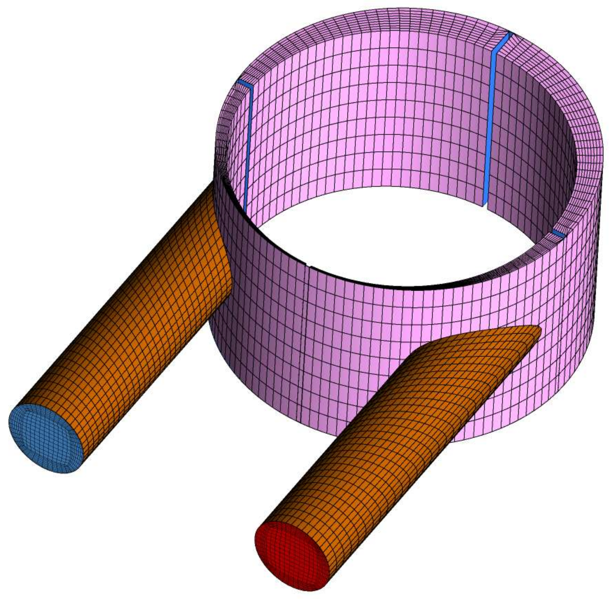
The movement of the multi-vane expander is inherently transient and its modelling required special treatment via transient boundary conditions. The model takes into account the rotational motion of the rotor and the vanes. For each time step the vanes radial position change hence the new topology of the numerical mesh is calculated and updated based on the equations of motion of the multi-vane expander. This allows for solution of the pressure, velocity and temperature fields inside a working chamber and provides precise information on the thermo-flow phenomena in a multi-vane expander, such as the internal leakages. The inlet and the outlet pipes remain stationary and they are connected with the rotor domain through the interface (see Figure 2). In each time step, the mesh was moved according to the following algorithm:
- An angular position of a vane defined by θ angle is calculated.
- A vane is rotated by an angle −θ to be aligned with X axis in the initial position of the mesh (see Figure 2).
- Nodes of a vane except the vane tip are elongated or shortened in the X direction. The nodes of the vane tip are just translated in the X direction.
- A vane is rotated back by an angle θ to its actual location.
- Nodes that lay on the rotor and cylinder surface are rotated by an angle β per time step. In the present work, β = 0.1° was used.
- The position of the internal nodes is calculated according to the following diffusion equationwhere δ is the displacement of boundary nodes relative to the previous mesh locations and Γdisp is the mesh stiffness, which determines the degree to which regions of nodes move together. For the present calculations, Γdisp = 1 was used.
Parameters at the inlet to the expander were selected to be temperature and pressure. For each working fluid, the inlet temperature was varied in a range of 40–90 °C with step of 10 degrees. The inlet pressure was taken as a saturation pressure of the working fluid at the inlet temperature. All calculations have been performed for a fixed cold source temperature (condenser temperature) equal to 20 °C.
The rotor rotational speed was assumed constant at a nominal value of 3000 rpm for all considered cases. The temperature at the outlet of the discharge socket was assumed 20 °C for all the cases and the pressure was set to the saturation pressure given by the medium properties.
3. Results and Discussion
3.1. Analysis of the Influence of the Applied Working Fluid
Figure 3 shows pressure distribution in a working chamber versus crank angle φ for different working fluids and different inlet temperatures. Due to the saturation pressure differs for each working fluid the p-φ curves are different however they follow the same shape. With increasing the inlet temperature, the inlet pressure (i.e., saturation pressure) increases and the area under the curve in the p-φ diagram increases. The highest inlet pressure occurred for propane and the lowest for acetone. Variation of the curves is known from typical volumetric expanders except the strange recompression effect which is visible in the vicinity of φ = 200°. This behavior stems from the improper construction of the expander and it was described in detail in [3]. This effect is more visible for working fluids with a higher saturation pressure and it results in decrease of efficiency of the expander. What is more, the arrangement of control edges in the analyzed machine is chosen improperly, which is visible in pressure distributions depicted in Figure 3. The working fluid is held in the working chamber for too long a time, which results in the occurrence of recompression and negative pressure fluctuations.
For the sake of better understanding of how a working fluid influences the expander’s performance, internal work was calculated as a difference between the inlet and the outlet enthalpy. The results of internal work are presented in Figure 4 in terms of pressure ratio (i.e., the ratio of the pressure at the inlet to the expander to the pressure at its outlet σ = pin/pout) for all working fluids used. Except the curve for acetone, all curves look similar in shape i.e., in the first phase they steeply increase and achieve a maximum in the range of σ = 3–4 (only propane for σ ≈ 2). Next, with increasing σ gradual decrease of internal work is observed. However, in the case of acetone, the characteristic behaves contrarily and the minimum is visible for σ ≈ 7. The results indicate that optimal pressure ratio for the rotary vane expander falls in the range of σ = 3–4. On the other side, the highest achievable internal work is obtained with propane for σ ≈ 2. However, it could be better understand via Figure 5 where the internal efficiency of the expander versus pressure ratio is plotted. It is obvious now that using propane as a working fluid in the expander analyzed is very ineffective and features very low efficiency of the order of 5%. However, Figure 5 also confirms that the optimal pressure ratio is located in the range of σ = 3–4 for which the efficiency is in the range of 12–35%. The highest efficiency can be achieved for the acetone, however the pressure ratio has to be increased to about σ ≈ 5.
3.2. Analysis of the Influence of the Arrangement of the Steering Edges
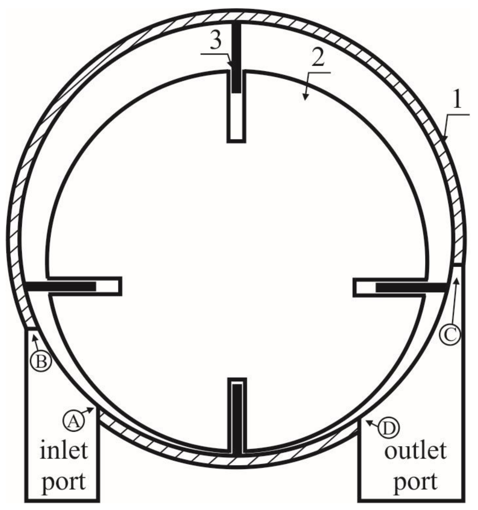
Figure 6 shows the cross section of a multi-vane expander with marked main subassemblies and edges (referred to as machine steering edges) of the inlet (A, B) and the outlet port (C, D).
Steering edges act as valves that control the timing of the machine, therefore their mutual arrangement has an influence on the hydraulic losses, thermodynamic phenomena occurring in the working chambers of the machine and its performance [30,42]. Reference [42] provides the general guidelines for the proper selection of the mutual arrangement of the steering edges. According to these guidelines, the cylinder should be manufactured in such a way that edge B of the inlet port should be placed in the area where the working chamber reaches its maximum volume. Edge A of the inlet port should be placed in the area where the pressure of the working fluid contained in the working chamber before filling is equal to the pressure of the working fluid in the suction line. Edge C of the outlet port should be placed in the area where the pressure of the working fluid contained in the working chamber after expansion is equal to the pressure of the working fluid in the discharge line. Edge D of the outlet port should be placed in the area where the working chamber reaches its minimum volume.
The indicator diagram valid for the ideal multi-vane expander with the properly arranged steering edges is shown in Figure 7. It corresponds to a 1-2-3-4 broken curve. The visualization of the improper arrangement of the steering edges is also presented on this Figure, i.e., 1a and 1b visualize the process of the late start of suction; 1c and 1d visualize the process of early start of suction; 3a and 3b visualize early start of evacuation; and 3c and 3d visualize late start of evacuation. Improper construction of steering edges results in pressure fluctuations and decline in internal work. Consequently, thermal efficiency of a multi-vane expander decreases.
In the following paragraph, numerical analysis of the influence of arrangement of the steering edges is performed and the results of the numerical modelling are presented.
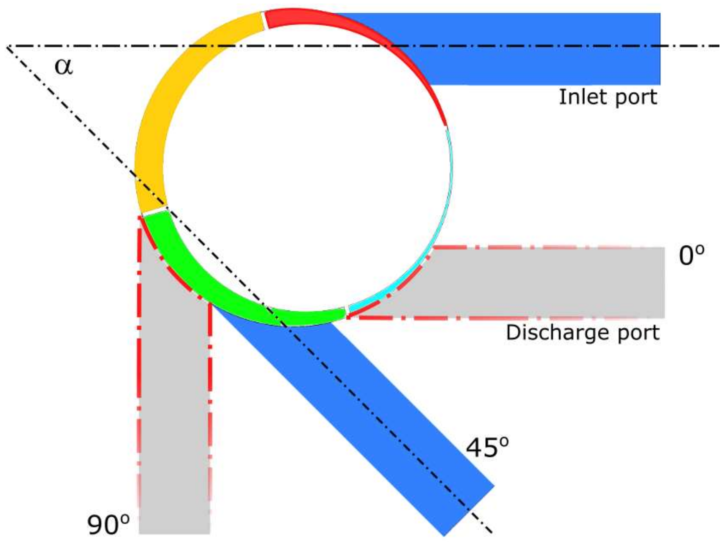
In order to numerically investigate the influence of machine steering edges on the expanders thermodynamic performance, modifications in the initial construction (referred to as 0° case) have been done. Figure 8 presents modified expander construction cases where machine steering edges are located in different places. Modification consisted in moving only the outlet port by a specified α angle while the inlet port remained in its initial position. The angle was varied by 22.5° and 0° corresponds to the initial position of the outlet port. The angles used were: 22.5°, 45°, 67.5°, and 90°. For these analysis purposes only, three working fluids were chosen, namely R123, R245fa, and R365mfc. Boundary conditions for each working fluid were set as stated in Table 2.
The choice of R245fa and R365mfc working fluids is dictated by previous analysis which showed that from all analysed working fluids these two allows one to achieve the highest efficiency (see Figure 5). Additionally, R123 was analyzed as a reference working fluid.
Figure 9 shows an exemplary variation of the pressure inside the working chamber against crank angle for the case of R365mfc and five different angles of the outlet port position. As one can observe the crank angle that corresponds to onset of expansion is independent of the position angle α of the outlet port and remains close to φ ≈ 90°. For the initial case, i.e., α = 0°, one can see the recompression effect that was mentioned earlier. When the position angle α of the outlet port increases, the recompression of the working fluid reduces and eventually ceases for α ≥ 67.5°. Simultaneously, the crank shaft angle at which working fluid is being evacuated from the working chamber decreases and the area under the curve in the p–V diagram increases, as is shown in Figure 10. Additionally, the pressure fluctuations described in previous paragraph resulted from improper location of the machine steering edges are lowered and eventually eliminated for α ≥ 67.5°.
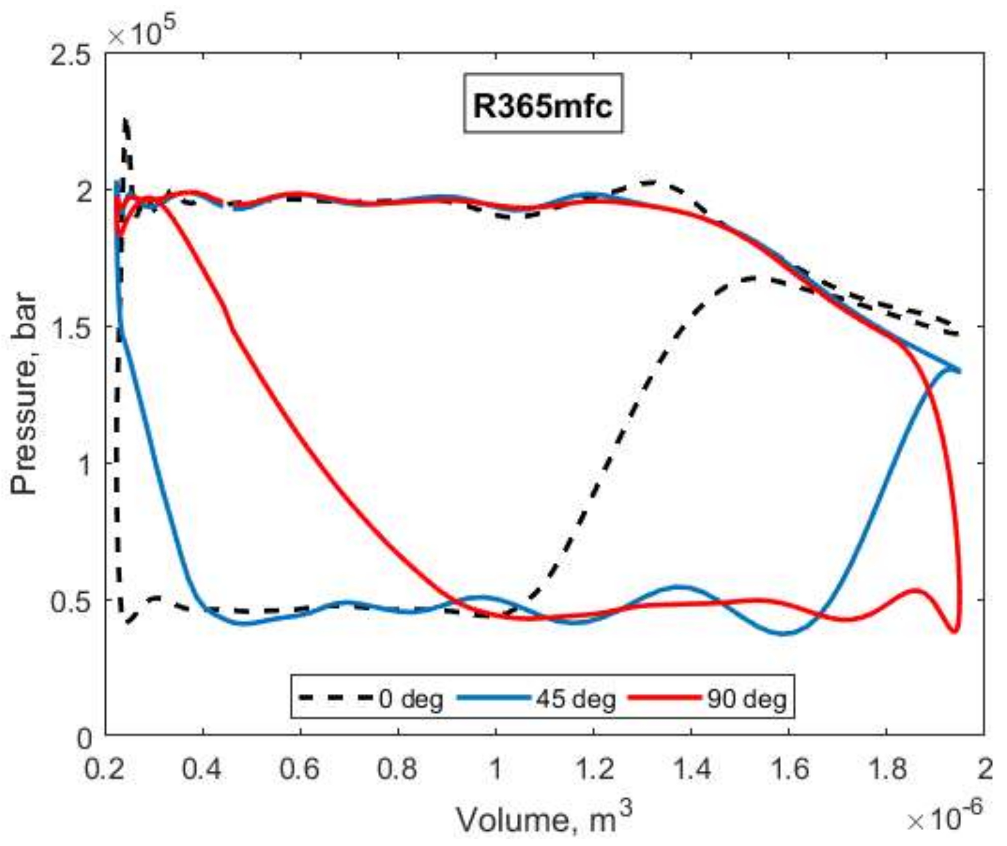
Elimination of the recompression effect and pressure fluctuations caused by improper design of the machine steering edges should result in better working conditions of the expander. To investigate this feature better, Figure 10 shows the p–V diagram of the expander for R365mfc as a working fluid and different location of the outlet port. For the initial case, i.e., α = 0° the recompression effect significantly decreases the area under p–V curve and the resulting internal work is also decreased. For the case of α = 45° the area under p–V curve is much bigger due to reduction of the recompression. However, it is also observed that moving the outlet port by α angle results in displacement of point 4 (see Figure 7) towards larger volumes. This results in displacement of the onset of compression stage in the expander which now starts for higher volumes in p–V diagram and the evacuation stage is decreased. This behavior could be better presented in Figure 11, where the working fluid mass m0 inside a working chamber is shown. It is visible that increasing α—i.e., moving the outlet port towards the inlet port—results in reducing the time of residence of the working fluid in the working chamber. Shorter time of residence of the working medium in the chamber advantageously limits the impact of the working fluid leakages between the adjacent working chambers. The mass flow into the chamber is distinctly higher for α < 45° due to adverse pressure difference between adjacent chambers. The high pressure at the chamber–outlet port interface caused by recompression results in increased leakage at the initial stage of expansion compared to the designs with α ≥ 45°. Also with increasing α angle, the mass of the working fluid inside the chamber before the filling phase is increased so the volumetric efficiency is lower. An earlier start of the evacuation also limits the energy losses related to recompression of the working fluid. On the other side, the area under p–V diagram is decreased and smaller internal work can be obtained. Nonetheless, according to Figure 10, for α = 45° net gain of the internal work is still positive. However, for the case of α = 90° the point 4 moves considerably on the right and the loss of the internal work is in this case larger than gain of the internal work due to elimination of the recompression phenomenon. It suggests the existence of an optimal steering edges arrangement for which the internal work is maximized.
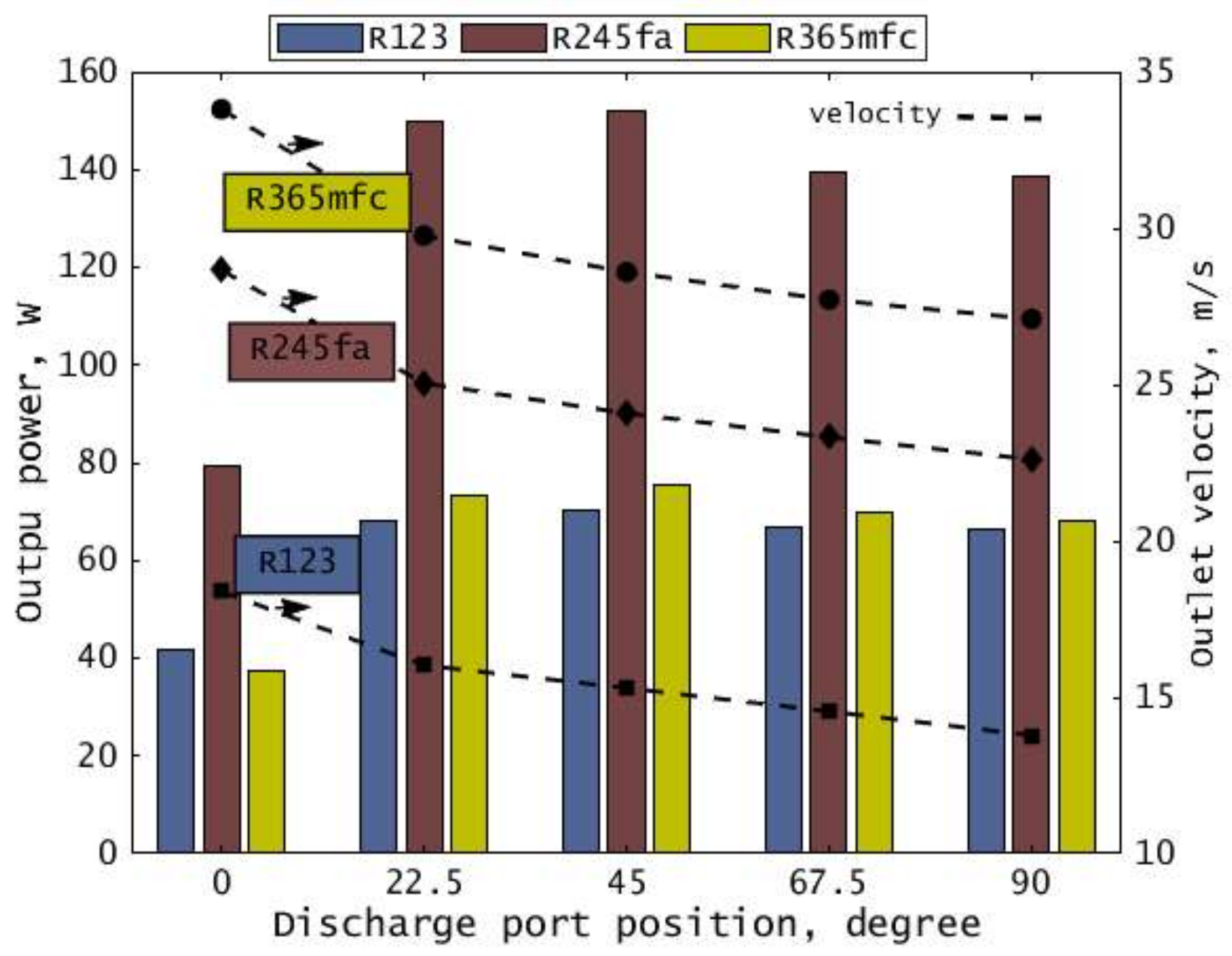
From the above considerations, one can infer that some optimal α angle should exist for which internal work and efficiency are the highest. To analyze it better, we calculated the output power and internal efficiency of the expander which are plotted in Figure 12 and Figure 13, respectively. Figure 12 shows values of output power (bars) and outlet velocity (dashed lines) for all working fluids used and different discharge port positions. The highest output power is always obtained for R245fa working fluid. The displacement of the discharge port position results in almost double increase of power output and outlet velocity for R245fa, compared to R123 and R365mfc working fluids. It is also observed that in the range of α = 22.5–67.5° the maximum of output power exists. This feature is reflected in Figure 13 where thermal efficiency of the expander is plotted. The optimal parameters occur for α ≈ 46°. For R245fa and R365mfc working fluids, the maximum thermal efficiencies are 45% and 47%, respectively. On the other hand, for R123 the maximum reaches more than 55%. These results show that modification of the initial construction of the expander via applying proper machine steering edges position can significantly increase the thermal efficiency.
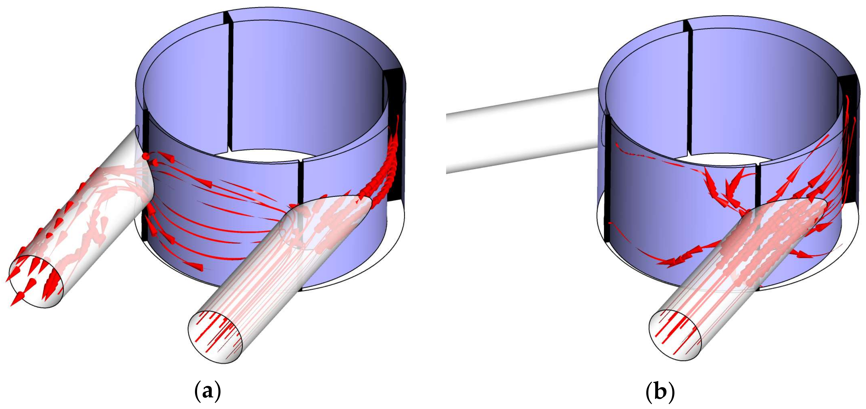
Such high improvement of the expander’s performance results from the proper arrangement of the machine steering edges which eliminates recompression and reduces pressure fluctuations. Additionally, the leakages between neighboring working chambers are limited as well. To understand it more precisely, Figure 14 shows the comparison of the size of the leakage from the inlet to the outlet port of the expander. For the initial construction of the expander (left figure) one can see that, for presented position of the vanes, the inlet and the outlet line are connected through the common working chamber. In this place, the highest pressure difference occurs and consequently it results in a large leaking mass flow. On the other side, for the improved construction (right figure) it is clearly visible that replacement of the outlet port positioning and thus change of the steering edges arrangement positively limits the impact of this phenomenon.
4. Summary and Conclusions
Three dimensional numerical analysis of a multi-vane expander was performed. The goal was to study the influence of the working fluid on the expander’s performance. Additionally, an influence of machine steering edges arrangement on thermo-flow phenomena occurring in the expander was thoroughly studied. The numerical model was validated against the experiments that were carried out using a prototype of domestic ORC system equipped with a small multi-vane expander featuring a power of 300 W and utilizing R123 as a working fluid. The main aim of experimental investigations was to gather the input data needed for creating a numerical model of the expander and analysis of its operating conditions with a variety of working fluids.
The geometry of the expander used during the experiments was created and next divided into small elements that comprised numerical mesh. Governing equations of continuity, momentum, and energy together with equations of motion of the expander’s elements were solved using commercial CFD tool. In order to analyze the influence of a working fluid on the expander’s performance, different working fluids were selected and used i.e., R1234yf, R1234ze, R134a, R245fa, R236fa, R365mfc, acetone, and propane. During the numerical simulations, the value of temperature on the expander’s inlet was varied similarly as during the experiments. It was found that for the expander analyzed and working fluids used, the optimal pressure ratio is in the range of σ = 3–4. Corresponding efficiency is in the range of 12–35% depending on working fluid. The numerical analysis showed that the best results were achieved for R245fa and R365mfc working fluids which featured the highest thermal efficiency.
On this basis R245fa, R365mfc, and R123 as a reference working fluid were used in the further step which was an attempt to optimize the expanders design in terms of efficiency. Based on calculated p–V diagrams, the influence of steering edges arrangement was recognized as a principal factor. The numerical model has been modified to include variable discharge port position relative to the rotors eccentricity allowing to control the timing of working fluid evacuation. It was found that an optimal position of the machine steering edges exists for which the internal work and the thermal efficiency are maximum. For the analyzed expander’s construction, the optimal position angle was α ≈ 46°. The obtained results show that the proper arrangement of the steering edges is crucial factor influencing the multi-vane expander performance and operating conditions.
Acknowledgments
Calculations have been carried out using resources provided by Wroclaw Center for Networking and Supercomputing (http://wcss.pl).
Author Contributions
Piotr Kolasiński conceived and designed the test stand and the experiments; Przemysław Błasiak and Józef Rak conceived and designed the numerical model; Piotr Kolasiński, Przemysław Błasiak and Józef Rak performed the experiments; Piotr Kolasiński, Przemysław Błasiak and Józef Rak analyzed the data; Piotr Kolasiński, Przemysław Błasiak and Józef Rak wrote the paper.
Conflicts of Interest
The authors declare no conflict of interest.
References
- Hung, T.C.; Shai, T.Y.; Wang, S.K. A review of Organic Rankine Cycles (ORCs) for the Recovery of Low-Grade Waste Heat. Energy 1997, 22, 661–667. [Google Scholar] [CrossRef]
- Kolasiński, P. The Influence of the Heat Source Temperature on the Multivane Expander Output Power in an Organic Rankine Cycle (ORC) System. Energies 2015, 8, 3351–3369. [Google Scholar] [CrossRef]
- Mikielewicz, J.; Mikielewicz, D.; Ihnatowicz, E.; Kaczmarczyk, T.; Wajs, J.; Matysko, R.; Bykuć, S.; Rybiński, W. Obiegi Termodynamiczne ORC Mikrosiłowni Domowej; Institute of Fluid-flow Machinery Publishing: Gdańsk, Poland, 2014; ISBN 978-83-88237-19-5. [Google Scholar]
- Stępień, R. Wybrane Zagadnienia Projektowania Wielostopniowych Mikroturbin Osiowych; Institute of Fluid-flow Machinery Publishing: Gdańsk, Poland, 2013; ISBN 978-83-88237-13-3. [Google Scholar]
- Kozanecki, Z.; Kozanecka, D.; Klonowicz, P.; Łagodziński, J.; Gizelska, M.; Tkacz, E.; Miazga, M.; Kaczmarek, A. Oil-Less Small Power Turbo-Machines (Bezolejowe Maszyny Przepływowe Małej Mocy); Institute of Fluid-flow Machinery Publishing: Gdańsk, Poland, 2014; ISBN 978-83-88237-27-0. [Google Scholar]
- Mikielewicz, D.; Mikielewicz, J.; Ihnatowicz, E.; Muszyński, T.; Wajs, J.; Rybiński, W. Wybrane Aspekty Projektowania i Badań Wymienników Ciepła Dla Obiegu ORC Mikrosiłowni Domowej; Institute of Fluid-flow Machinery Publishing: Gdańsk, Poland, 2013. [Google Scholar]
- Kaniecki, M.; Henke, A.; Krzemianowski, Z. Agregaty Pompowe w Zastosowaniu do Obiegów ORC Mikrosiłowni Kogeneracyjnych na Czynnik Niskowrzący; Institute of Fluid-flow Machinery Publishing: Gdańsk, Poland, 2013; ISBN 978-83-88237-14-0. [Google Scholar]
- Kiciński, J.; Żywica, G. Dynamika Mikroturbin Parowych; Institute of Fluid-flow Machinery Publishing: Gdańsk, Poland, 2014. [Google Scholar]
- Breńkacz, Ł.; Żywica, G.; Bogulicz, M. Selection of the Bearing System for a 1 kW ORC Microturbine. In Proceedings of the 31st Workshop on Turbomachinery, Dresden, Germany, 4–6 October 2017. [Google Scholar]
- Żywica, G.; Kaczmarczyk, T.; Ihnatowicz, E.; Turzyński, T. Experimental investigation of the domestic CHP ORC system in transient operating conditions. Energy Procedia 2017, 129, 637–643. [Google Scholar] [CrossRef]
- Kaczmarczyk, T.; Żywica, G.; Ihnatowicz, E. The impact of changes in the geometry of a radial microturbine stage on the efficiency of the micro CHP plant based on ORC. Energy 2017, 137, 530–543. [Google Scholar] [CrossRef]
- Kaczmarczyk, T.; Żywica, G.; Ihnatowicz, E. Vibroacoustic diagnostics of a radial microturbine and a scroll expander operating in the organic Rankine cycle installation. J. Vibroeng. 2016, 18, 4130–4147. [Google Scholar] [CrossRef]
- Kaczmarczyk, T.; Żywica, G.; Ihnatowicz, E. The Experimental Investigation of the Biomass-Fired ORC System with a Radial Microturbine. Appl. Mech. Mater. 2016, 831, 235–244. [Google Scholar] [CrossRef]
- Kaczmarczyk, T.; Żywica, G.; Kiciński, J.; Ihnatowicz, E.; Turzyński, T.; Bykuć, S. Prototype of the Domestic CHP ORC System: Construction and Experimental Research. In Proceedings of the 3rd International Seminar on ORC Power Systems, Brussels, Belgium, 12–14 October 2015. [Google Scholar]
- Kaczmarczyk, T.; Żywica, G.; Ihnatowicz, E. Experimental Investigation of a Radial Microturbine in Organic Rankine Cycle System with HFE7100 as Working Fluid. In Proceedings of the 3rd International Seminar on ORC Power Systems, Brussels, Belgium, 12–14 October 2015. [Google Scholar]
- Klonowicz, P.; Witanowski, Ł.; Jędrzejewski, Ł.; Suchocki, T.; Lampart, P. A turbine based domestic micro ORC system. Energy Procedia 2017, 129, 923–930. [Google Scholar] [CrossRef]
- Klonowicz, P.; Borsukiewicz-Gozdur, A.; Hanausek, P.; Kryłłowicz, W.; Brüggemann, D. Design and performance measurements of an organic vapour turbine. Appl. Therm. Eng. 2014, 63, 297–303. [Google Scholar] [CrossRef]
- Klonowicz, P.; Heberle, F.; Preißinger, M.; Brüggemann, D. Significance of loss correlations in performance prediction of small scale, highly loaded turbine stages working in Organic Rankine Cycles. Appl. Therm. Eng. 2014, 72, 322–330. [Google Scholar] [CrossRef]
- Lemort, V.; Giullaume, L.; Legros, A.; Declaye, S.; Quoilin, S. A Comparison of Piston, Screw and Scroll Expanders for Small Scale Rankine Cycle Systems. In Proceedings of the 3rd International Conference on Microgeneration and Related Technologies, Naples, Italy, 15–17 April 2013. [Google Scholar]
- Song, P.P.; Zhuge, W.L.; Zhang, Y.J.; Zhang, L.; Duan, H. Unsteady Leakage Flow Through Axial Clearance of an ORC Scroll Expander. Energy Procedia 2017, 129, 355–362. [Google Scholar] [CrossRef]
- Kosmadakis, G.; Mousmoulis, G.; Manolakos, D.; Anagnostopoulos, I.; Papadakis, G.; Papantonis, D. Development of Open-Drive Scroll Expander for an Organic Rankine Cycle (ORC) Engine and First Test Results. Energy Procedia 2017, 129, 371–378. [Google Scholar] [CrossRef]
- Garg, P.; Karthik, G.M.; Kumar, P.; Kumar, P. Development of a generic tool to design scroll expanders for ORC applications. Appl. Therm. Eng. 2016, 109, 878–888. [Google Scholar] [CrossRef]
- Gao, P.; Jiang, L.; Wang, L.W.; Wang, R.Z.; Song, F.P. Simulation and experiments on an ORC system with different scroll expanders based on energy and exergy analysis. Appl. Therm. Eng. 2015, 75, 880–888. [Google Scholar] [CrossRef]
- Cao, Z.; Su, J.C.; Liu, Y.L.; Guo, B.; Chen, J.F. System Efficiency Comparison of Single-stage ORC with Twin-stage ORC Using Scroll Expanders. In Proceedings of the International Conference on Energy and Environment Engineering (ICEEE 2015), Nanjing, China, 11–12 April 2015. [Google Scholar]
- Declaye, S.; Quoilin, S.; Guillaume, L.; Lemort, V. Experimental study on an open-drive scroll expander integrated into an ORC (Organic Rankine Cycle) system with R245fa as working fluid. Energy 2013, 55, 173–183. [Google Scholar] [CrossRef]
- Kaczmarczyk, T.; Ihnatowicz, E.; Żywica, G.; Kiciński, J. Experimental investigation of the ORC system in a cogenerative domestic power plant with a scroll expanders. Open Eng. 2015, 5, 411–420. [Google Scholar] [CrossRef]
- Fiaschi, D.; Secchi, R.; Galoppi, G.; Tempesti, D.; Ferrara, G.; Ferrari, L.; Karellas, S. Piston Expanders Technology as a Way to Recover Energy from the Expansion of Highly Wet Organic Refrigerants. In Proceedings of the ASME 9th International Conference on Energy Sustainability, San Diego, CA, USA, 28 June–02 July 2015. [Google Scholar]
- Oudkerk, J.F.; Dickes, R.; Dumont, O.; Lemort, V. Experimental Performance of a Piston Expander in a Small-Scale Organic Rankine Cycle. In Proceedings of the 9th International Conference on Compressors and Their Systems, London, UK, 5–9 September 2015. [Google Scholar]
- Norwood, Z.; Kammen, D.; Dibble, R. Testing of the Katrix rotary lobe expander for distributed concentrating solar combined heat and power systems. Energy Sci. Eng. 2014, 2, 61–76. [Google Scholar] [CrossRef]
- Gnutek, Z.; Kolasiński, P. The application of rotary vane expanders in organic Rankine cycle systems—Thermodynamic description and experimental results. J. Eng. Gas Turbines Power 2013, 135, 61901. [Google Scholar] [CrossRef]
- Kolasiński, P.; Błasiak, P.; Rak, J. Experimental investigation on multi-vane expander operating conditions in domestic CHP ORC system. Energy Procedia 2017, 129, 323–330. [Google Scholar] [CrossRef]
- Murgia, S.; Valenti, G.; Colletta, D.; Costanzo, I.; Contaldi, G. Experimental investigation into an ORC-based low-grade energy recovery system equipped with sliding-vane expander using hot oil from an air compressor as thermal source. Energy Procedia 2017, 129, 339–346. [Google Scholar] [CrossRef]
- Cipollone, R.; Contaldi, G.; Bianchi, G.; Murgia, S. Energy Recovery Using Sliding Vane Rotary Expanders. In Proceedings of the 8th International Conference on Compressors and Their Systems, London, UK, 9–10 September 2013. [Google Scholar]
- Cipollone, R.; Bianchi, G.; Di Battista, D.; Contaldi, G.; Murgia, S. Mechanical energy recovery from low grade thermal energy sources. Energy Procedia 2014, 45, 121–130. [Google Scholar] [CrossRef]
- Cipollone, R.; Bianchi, G.; Gualtieri, A.; Di Battista, D.; Mauriello, M.; Fatigati, F. Development of an Organic Rankine Cycle system for exhaust energy recovery in internal combustion engines. J. Phys. Conf. Ser. 2015, 655, 12015. [Google Scholar] [CrossRef]
- Montenegro, G.; Della Torre, A.; Fiocco, M.; Onorati, A.; Benatzky, C.; Schlager, G. Evaluating the Performance of a Rotary Vane Expander for Small Scale Organic Rankine Cycles using CFD tools. In Proceedings of the ATI 2013—68th Conference of the Italian Thermal Machines Engineering Association, Bologna, Italy, 11–13 September 2013. [Google Scholar]
- Kolasiński, P.; Błasiak, P.; Rak, J. Experimental and Numerical Analyses on the Rotary Vane Expander Operating Conditions in a Micro Organic Rankine Cycle System. Energies 2016, 9, 606. [Google Scholar] [CrossRef]
- Vodicka, V.; Novotny, V.; Mascuch, J.; Kolovratnik, M. Impact of major leakages on characteristics of a rotary vane expander for ORC. Energy Procedia 2017, 129, 387–394. [Google Scholar] [CrossRef]
- Bianchi, G.; Rane, S.; Kovacevic, A.; Cipollone, R.; Murgia, S.; Contaldi, G. Grid Generation Methodology and CFD Simulations in Sliding Vane Compressors and Expanders. In Proceedings of the 10th International Conference on Compressors and Their Systems, London, UK, 9–13 September 2017. [Google Scholar]
- Rak, J.; Błasiak, P.; Kolasiński, P. Numerical modelling of multi-vane expander operating conditions in ORC systems. In Proceedings of the International Conference on Advances in Energy Systems And Environmental Engineering (ASEE17), Wrocław, Poland, 2–5 July 2017. [Google Scholar]
- Bianchi, G.; Fatigati, F.; Murgia, S.; Cipollone, R.; Contaldi, G. Modeling and experimental activities on a small-scale sliding vane pump for ORC-based waste heat recovery applications. Energy Procedia 2016, 101, 1240–1247. [Google Scholar] [CrossRef]
- Warczak, W. Refrigerating Compressors; WNT: Warsaw, Poland, 1987. [Google Scholar]
Figure 1.
A general view of the expander. (1) cylinder; (2) rotor; (3) vanes; (4) end covers; (5) rolling bearings; (6) rings.
Figure 1.
A general view of the expander. (1) cylinder; (2) rotor; (3) vanes; (4) end covers; (5) rolling bearings; (6) rings.
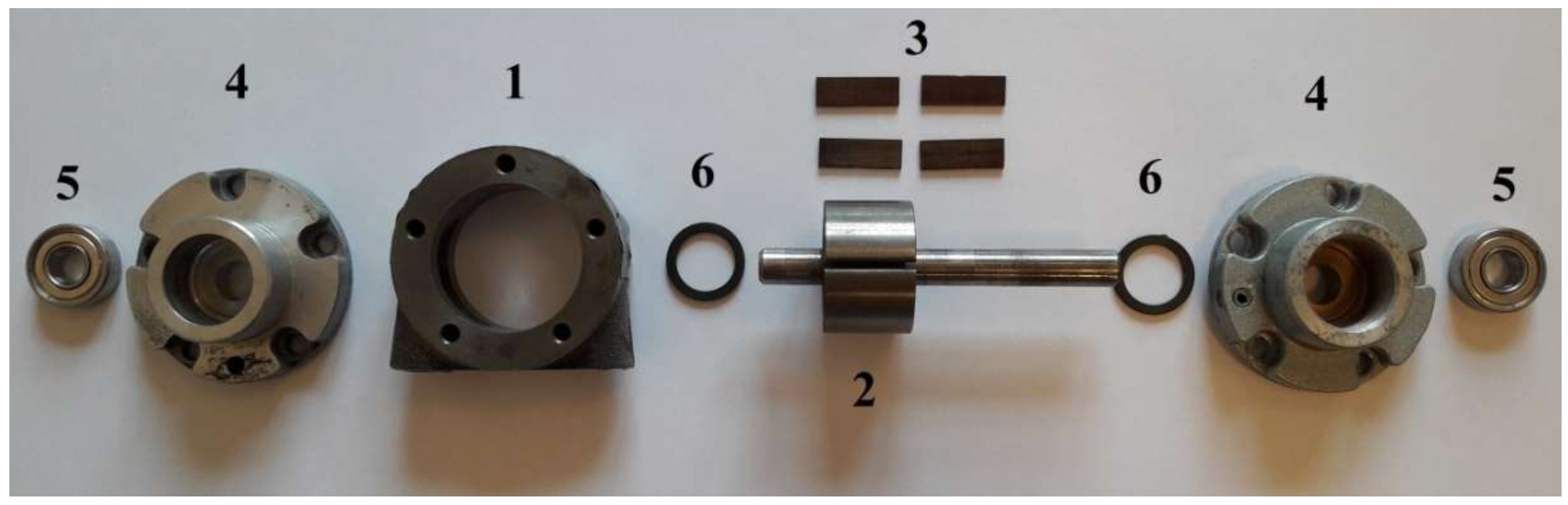
Figure 2.
The initial position of the numerical mesh of the computational model at crank angle φ = 0°. The working fluid flow was modelled as a compressible, turbulent, and single-phase Redlich–Kwong gas. The specific heat capacity of each tested medium was set as a function of temperature. The wall boundary was assumed adiabatic due to the brief time spent by a portion of the fluid inside the machine (see Table 1).

Figure 3.
Pressure distribution against crank angle for different working fluids and inlet temperatures: (a) tin = 40 °C; (b) tin = 50 °C; (c) tin = 60 °C; (d) tin = 70 °C; (e) tin = 80 °C; (f) tin = 90 °C.
Figure 3.
Pressure distribution against crank angle for different working fluids and inlet temperatures: (a) tin = 40 °C; (b) tin = 50 °C; (c) tin = 60 °C; (d) tin = 70 °C; (e) tin = 80 °C; (f) tin = 90 °C.
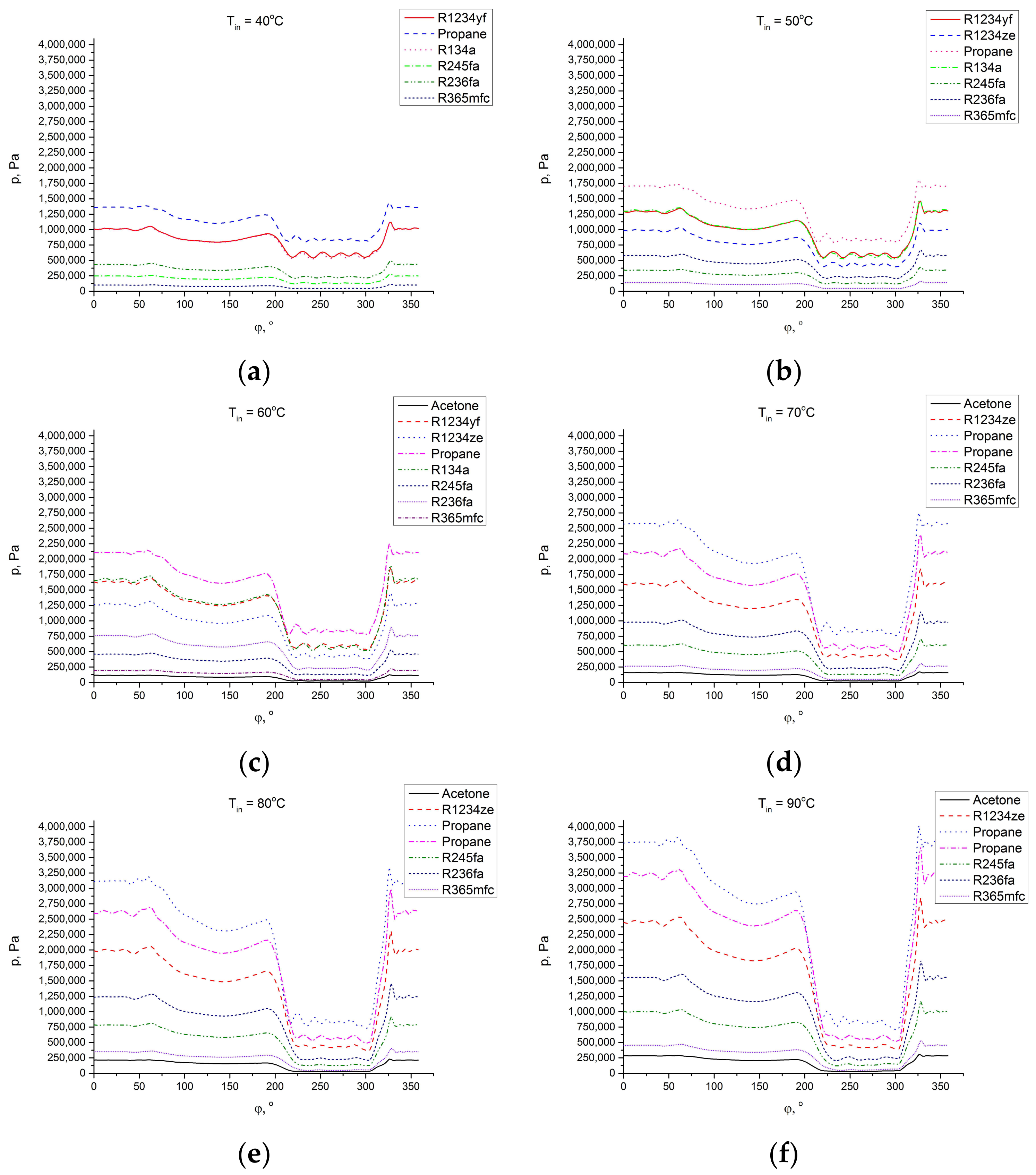
Figure 4.
Internal work against pressure ratio for different working fluids.

Figure 5.
Efficiency against pressure ratio for different working fluids.

Figure 6.
The cross section of the multi-vane expander at 0° crank angle. (1) cylinder; (2) rotor; (3) vane.
Figure 6.
The cross section of the multi-vane expander at 0° crank angle. (1) cylinder; (2) rotor; (3) vane.

Figure 7.
The multi-vane expander indicator diagram.

Figure 8.
The modified multi-vane expander’s construction with different locations of machine steering edges (α = 0°, 22.5°, 45°, 67.5°, and 90°).
Figure 8.
The modified multi-vane expander’s construction with different locations of machine steering edges (α = 0°, 22.5°, 45°, 67.5°, and 90°).

Figure 9.
Pressure variation in a working chamber for R365mfc and different outlet port locations.
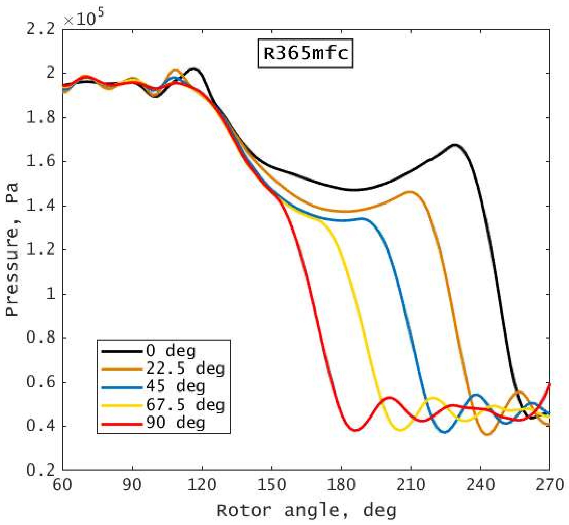
Figure 10.
P–V diagram of the expander for R365mfc and different outlet port locations.

Figure 11.
Mass of the working fluid in the working chamber of the expander versus rotor crank angle and different outlet port locations.
Figure 11.
Mass of the working fluid in the working chamber of the expander versus rotor crank angle and different outlet port locations.
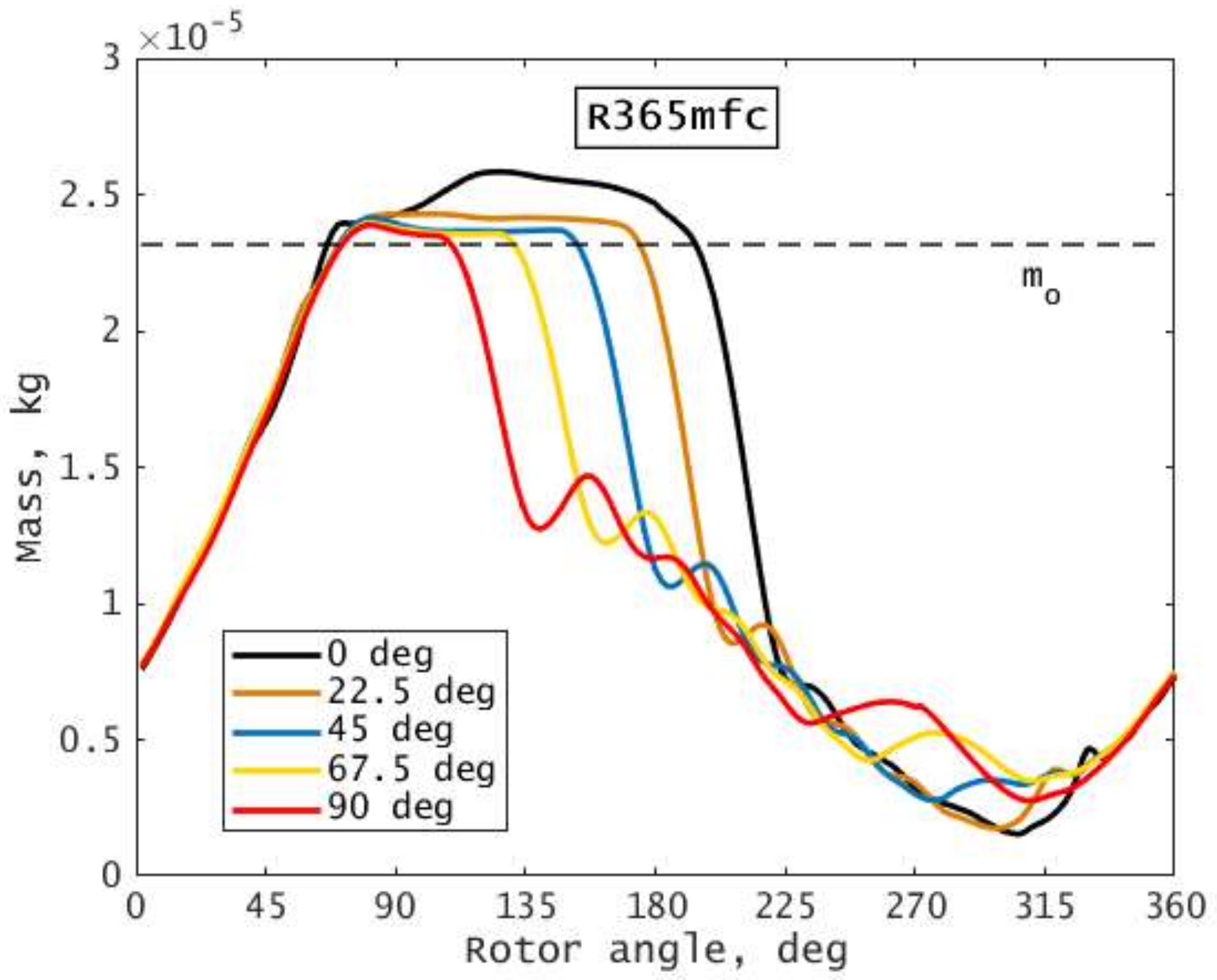
Figure 12.
Output power and outlet velocity for different working fluids and different discharge port positions.
Figure 12.
Output power and outlet velocity for different working fluids and different discharge port positions.

Figure 13.
Variation of thermal efficiency of the expander for different working fluids and different outlet port positions.
Figure 13.
Variation of thermal efficiency of the expander for different working fluids and different outlet port positions.
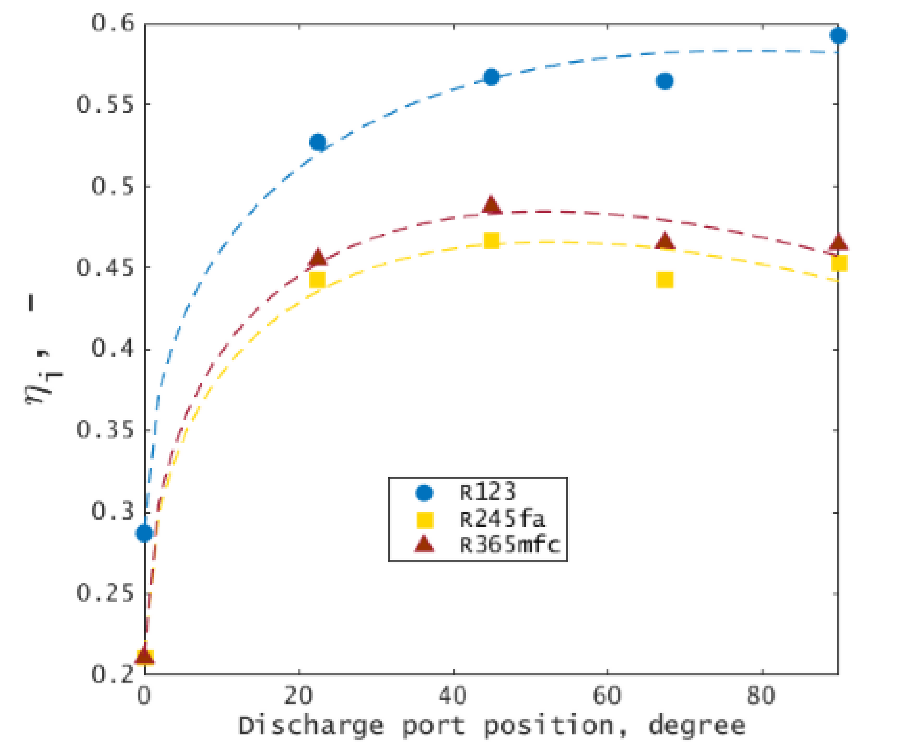
Figure 14.
The visualization of leakage from the inlet to the outlet port of the expander: (a) present design; (b) improved design.
Figure 14.
The visualization of leakage from the inlet to the outlet port of the expander: (a) present design; (b) improved design.


Table 1.
Boundary conditions and model assumptions.
| Parameter | Value | Remarks |
|---|---|---|
| Inlet temperature | 40–90 °C | With steps of 10 degrees |
| Inlet pressure | Type of the working fluid and its saturation pressure at the inlet temperature | - |
| Condenser temperature | 20 °C | - |
| Condenser pressure | Saturation pressure at 20 °C | depending on the working fluid |
| Time step | 5.5 × 10⁻⁵ s | 1 degree of revolution |
| Total time | 0.1 s | 5 full revolutions |
| Turbulence model | k-epsilon | Standard model |
| Wall heat transfer | Adiabatic | - |
| Vane-to-wall clearance | 40 μm | constant |
Table 2.
Boundary conditions and model assumptions
| Working Medium | tin | pin | σ | n |
|---|---|---|---|---|
| °C | bar | - | rpm | |
| R123 | 60 °C | 2.86 | 3.6 | 3000 |
| R245fa | 4.63 | 4.3 | ||
| R365mfc | 1.97 | 2.0 |
© 2018 by the authors. Licensee MDPI, Basel, Switzerland. This article is an open access article distributed under the terms and conditions of the Creative Commons Attribution (CC BY) license (http://creativecommons.org/licenses/by/4.0/).
Share and Cite
MDPI and ACS Style
Rak, J.; Błasiak, P.; Kolasiński, P. Influence of the Applied Working Fluid and the Arrangement of the Steering Edges on Multi-Vane Expander Performance in Micro ORC System. Energies 2018, 11, 892. https://doi.org/10.3390/en11040892
AMA Style
Rak J, Błasiak P, Kolasiński P. Influence of the Applied Working Fluid and the Arrangement of the Steering Edges on Multi-Vane Expander Performance in Micro ORC System. Energies. 2018; 11(4):892. https://doi.org/10.3390/en11040892
Chicago/Turabian StyleRak, Józef, Przemysław Błasiak, and Piotr Kolasiński. 2018. "Influence of the Applied Working Fluid and the Arrangement of the Steering Edges on Multi-Vane Expander Performance in Micro ORC System" Energies 11, no. 4: 892. https://doi.org/10.3390/en11040892
Note that from the first issue of 2016, this journal uses article numbers instead of page numbers. See further details here.