1. Introduction
With the technical requirements of lightning protection, communication, energy conservation, and DC de-icing considered, the grounding mode of optical fiber composite overhead ground wire (OPGW) usually is of the type of being grounded at a single point, being grounded at every tower, or being grounded at one tower. The type used should be determined by a comparison of technology and economy. At present, OPGW is generally grounded at every tower, yet common ground wire mainly uses graded insulation and being grounded at a single point. There is a degree of induction voltage, electrostatic induction current, and electromagnetic induction current on ground wire because of electrostatic coupling and electromagnetic induction between ground wire and the transmission line; in that case, circulating current loss happens in OPGW, which negatively affects the diminishing line loss and energy economy.
On the other hand, the difference in the grounding method between OPGW and common ground wire in the same tower increases the possibility of lightning strikes on OPGW and the problem of breaking stock [
1,
2,
3,
4]. So, it is necessary to improve the OPGW’s grounding mode. In order to reduce the electromagnetic induction current and power loss caused by the overhead ground wire being grounded at every tower, it is appropriate to adopt the grounding mode of single-point grounding. The earth point could be set on the top or the middle of the overhead ground wire.
In order to satisfy the need for DC de-icing of OPGW in winter, it is necessary to do an insulation reconstruction of the OPGW. Since the 2008 mass ice disaster, State Grid Corporation of China (SGCC) and China Southern Power Grid (CSG )have performed insulation reconstruction for the purpose of DC de-icing of the OPGW of multiple 110~500 kV AC transmission lines [
5,
6,
7]. After reconstruction, the OPGW is connected with the tower by a ground wire insulator which should be equipped with a parallel discharge gap. The choice of gap distance is key of the application of the parallel gap. However, related articles [
8,
9,
10,
11,
12,
13,
14,
15,
16,
17,
18,
19,
20] do not confirm the method of choosing or the requirements of the parameters. Electrical requirements and technical conditions of the parallel discharge gap need to be studied further in order to confirm a suitable gap distance.
With large-scale construction of UHV AC transmission lines and large-scale adoption of OPGW in this construction, ground wire loss per kilometer will be remarkable; this is bad for energy saving if the grounding mode of the OPGW is not reasonable. The lightning trip-out rate of a UHV AC transmission line has a relatively high requirement, so it must be limited to under 0.1 times per hundred kilometers per year (translating into 40 thunderstorms per day) [
21]. The growing demand for wires and ground wire de-icing is more and more important since the 2008 mass ice disaster. Therefore, according to power loss, anti-lightning performance, and de-icing demand, we should choose a suitable grounding mode for OPGW in UHV AC transmission lines [
19,
20,
21,
22,
23].
This paper first gives the electrical requirement of the parallel discharge gap for OPGW DC de-icing. At normal operation, under the DC de-icing condition, and under the condition of lightning, the OPWG’s ground insulator electrical characteristics of the parallel discharge gap are analyzed. The recommended values are given in line with the requirements of the parallel discharge gap distance. Then, taking the north Zhejiang to Fuzhou UHV AC transmission line as an example, we combine theoretical analysis and simulation computations to research the influence of AC transmission line power loss and line lightning protection performance on different grounding modes of OPGW. Finally, the optimum grounding mode of OPGW is given.
2. Common De-Icing Connection Modes and Requirements of OPGW and Common Ground Wire
2.1. De-Icing Connection Modes
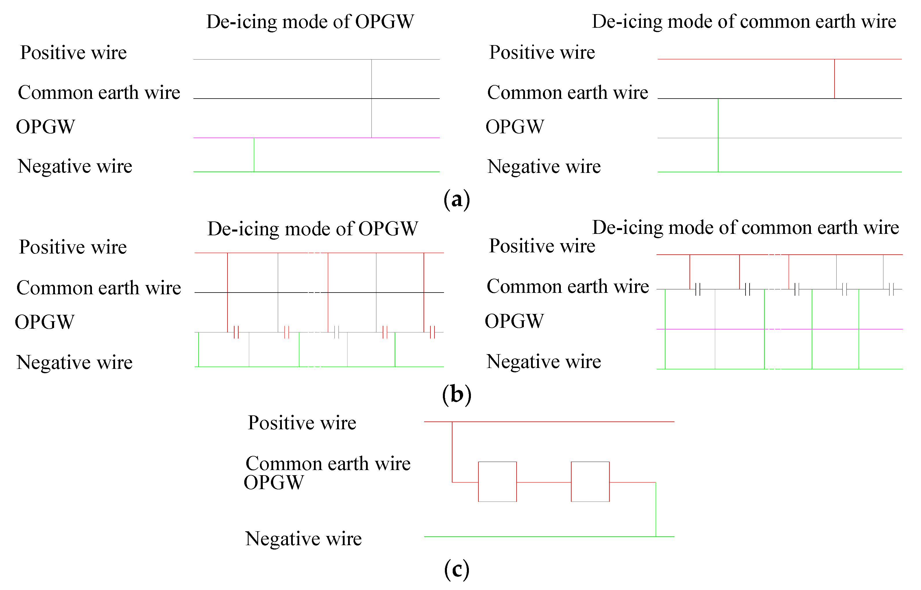
In Connection Mode 1, the de-icing mode of OPGW and common ground wire form a loop circuit by lead lines. If the two ground wires are an OPGW and a common ground wire, generally we do de-icing by Connection Mode 1. This connection mode is shown in
Figure 1a. Connection Mode 2 is a parallel multiple de-icing mode. In the parallel de-icing mode, the OPGW has been repeated parallel with the common ground wire, and forms a loop circuit by way of a quarter-phase line. This connection mode is shown in
Figure 1b. In Connection Mode 3, the OPGW has a parallel with the common ground wire and then connects in series with two circuits. This program is mainly aimed at single and double hybrid lines. This de-icing mode is shown in
Figure 1c.
2.2. De-Icing Requirements
Whether the OPGW de-icing programs use series or parallel connections, the OPGW must afford a range of de-icing voltages. The peak voltage of OPGW is generally ±20 kV, and voltage distribution on the OPWG from the power end to the grounding end is 0~±20 kV, so the grounding mode of OPGW must be changed from being grounded at every tower to single-point grounding. The earth point can be set on the top or the middle of the overhead ground wire.
3. Electrical Requirements and Gap Distance Selection for Parallel Discharge Gap on OPGW DC De-Icing Insulation Transformation
3.1. Structure of Ground Wire Insulator and Parallel Discharge Gap
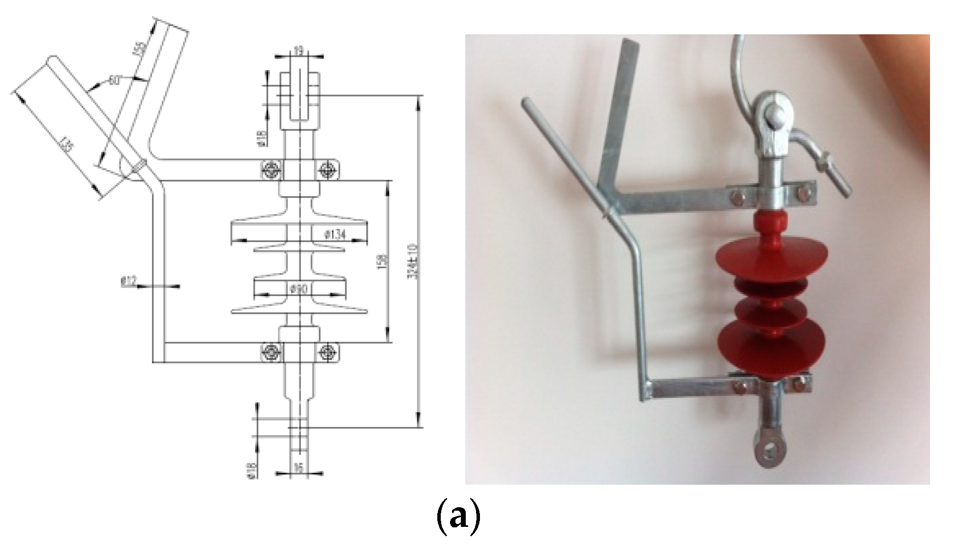
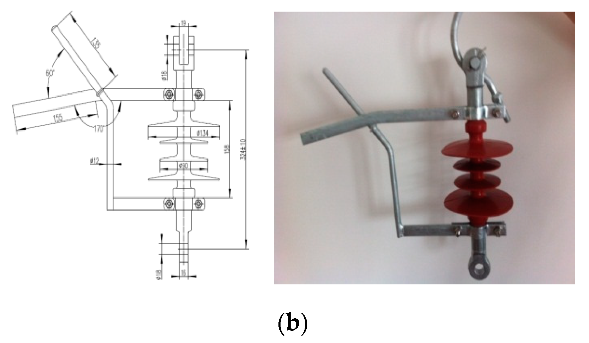
The structures of the ground wire insulator and parallel gap are shown in
Figure 2. In
Figure 2a,b are shown the pendant and tension structure charts of the ground wire insulator and parallel discharge gap, respectively. The technical parameters of the ground wire insulator are shown in
Table 1. The parallel gap is composed of two electric poles which are installed on fittings; one pole is fixed on the tower and the other is connected with the pre-twisted suspension clamp of OPGW. The distance of the electric poles can be adjusted by voltage level, and the guide arc poles which are installed on the OPGW are made of heat-resistant steel.
3.2. Electrical Requirements for Ground Wire Insulator and Parallel Discharge Gap in OPGW DC De-Icing Insulation Transformation
The electrical requirements for the OPGW DC de-icing insulation reconstruction of the ground wire insulator and parallel discharge gap are as follows:
- (1)
The ground wire insulator and parallel gap should not be broken under the influence of line-induced voltage, and power frequency discharge voltage with the parallel gap should be less than the power frequency withstand voltage without the gap.
- (2)
The ground wire insulator and parallel gap should not be broken under the influence of the DC de-icing voltage.
- (3)
The parallel gap of the ground wire insulator should break under the influence of lightning in order to protect the insulator.
3.3. Requirements of Parallel Gap Power Frequency Discharge Voltage and the Selection of Gap Distance for the Parallel Discharge Gap
(1) Requirements of Parallel Gap Power Frequency Discharge Voltage
It is known from the above calculation results that the induced voltage of the ground wire is limited to under 1 kV; that is, the maximum power frequency voltage of the ground wire insulator and parallel gap is under 1 kV. If the safety factor is 1.15, valid values of the power frequency withstand voltage between the ground wire insulator and parallel gap should be above 1.15 kV. At the same time, the parallel gap should also meet the requirements of insulation of the ground wire insulator, which means that the power frequency discharge voltage of the parallel gap should be less than the power frequency withstand voltage of the ground wire insulator without a parallel gap.
The DXF—160 CN is a pendant insulator and the DXF—100 C is a tension insulator which cannot be broken in 75 kV. The safety factor is 1.15, so the power frequency discharge voltage of the parallel gap should be under 75 kV ÷ 1.15 = 65 kV.
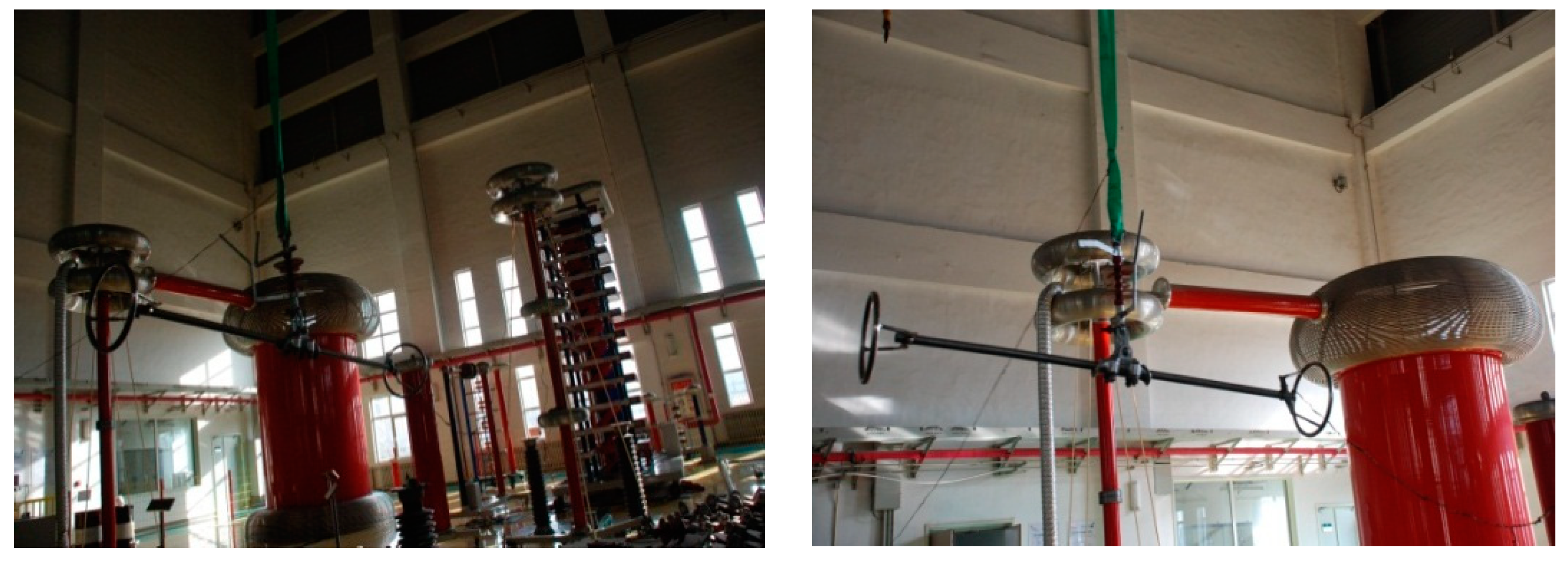
(2) Testing of Power Frequency Discharge Voltage and Withstand Voltage of the Parallel Gap
Images of the setup for power frequency discharge voltage tests of the ground wire insulator and parallel gap in the UHV DC base of SGCC are shown in
Figure 3. From such pictures, the situation of the test site can be seen, including power, transformer, and test products. The results of the tests are shown in
Table 2. As shown in
Table 2, the power frequency discharge voltages (effective values) all fall in the range of 1.15~65 kV when the distance of the parallel gap is 20~100 mm.
4. Electrical Requirement of OPGW Ground Wire Insulator and Parallel Gap in the Case of Ground Wire DC De-Icing
4.1. Requirements and Conditions of Icing Withstand Voltage Testing
The icing withstand voltage of the ground wire insulator and parallel gap should be higher than the maximum DC de-icing voltage that ground wire DC de-icing needs. Icing experiments have been made [
8,
9,
10,
11,
12,
13]. The following test conditions were formulated.
- (1)
Rated voltage was −20 kV;
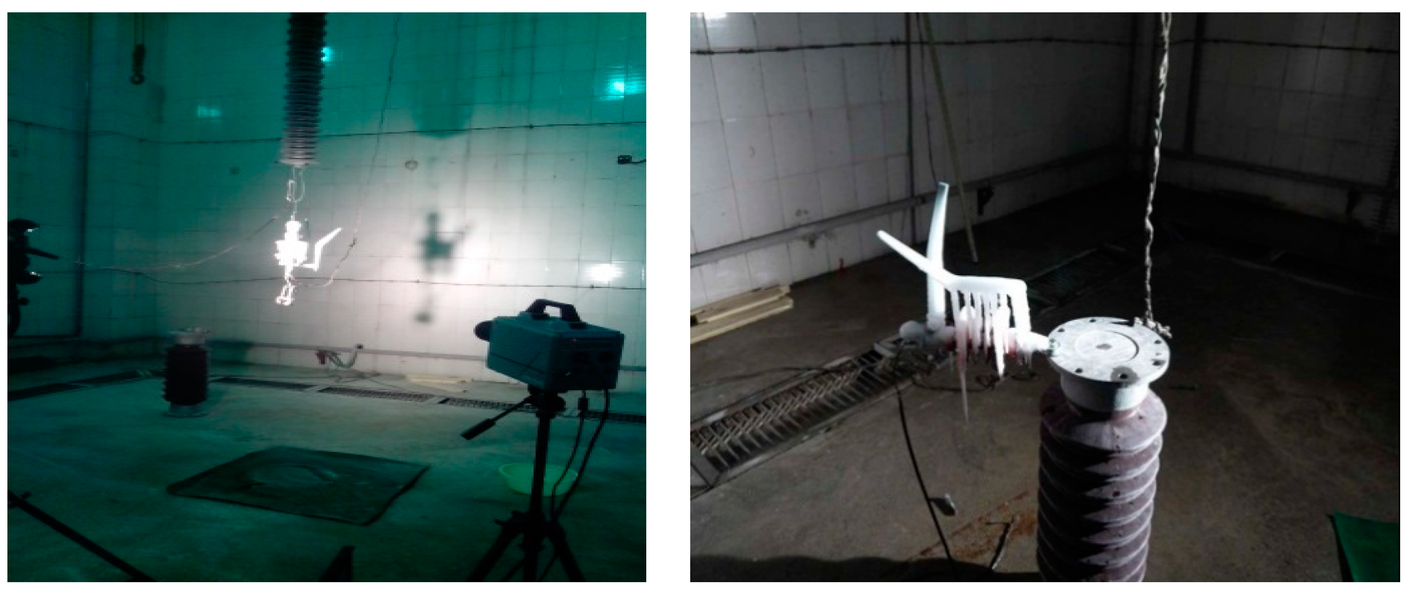
- (2)
The structure of the insulator is shown in
Figure 1. Icing withstand voltage test pictures are shown in
Figure 4. Tests were carried out in the UHV DC base of SGCC;
- (3)
The tested distances of the parallel gap were 60 mm, 80 mm, and 100 mm;
- (4)
Icing thickness tested were 20 mm and 30 mm (heavy icing area);
- (5)
Salt deposit density 0.08 mg/cm2, non-soluble deposit density 1.0 mg/cm2;
- (6)
The pressure method used was the booster method.
4.2. Test Results
The icing test results of the ground wire insulator and parallel discharge clearance are shown in
Table 3.
From
Table 3, some conclusions can be made. The DC de-icing voltage is −20 kV. In consideration of overthrow about ±10%, the highest DC de-icing voltage reached is −22 kV. The icing withstand voltage of the ground wire insulator and parallel gap should be higher than the maximum DC de-icing voltage of −22 kV that the ground wire DC de-icing needs. If the maximum icing-thickness is 30 mm, the gap distance should be above 60 mm. In consideration of the dispensability of gap discharging, the gap distance should be larger, so 70~80 mm is suggested.
5. The Influence of UHV AC Line Lightning Protection Performance on Different Grounding Modes of OPGW
5.1. The Requirement of a Ground Wire OPGW Insulator and Parallel Gap in the Case of Lightning
In the case of lightning, the lightning impact discharge voltage of the parallel gap should be less than the lightning impact withstand voltage of the ground wire insulator. That is to say, the parallel gap should be broken reliably to protect the ground wire insulator in the case of lightning. Generally, a ratio of minimal arc distance of the parallel gap and ground wire insulator between 80% and 85% can meet the requirements. When the minimal arc distance of the parallel gap is more than 158 mm and the parallel gap distance is between 126.4 mm and 134.3 mm, the parallel gap is broken before the ground wire insulator. In this paper, if the parallel gap distance is 70 mm and 80 mm, the requirement that the parallel gap is broken before the ground wire insulator can be met.
5.2. Lightning Over-Voltage Calculation of a 220 kV Ground Wire Insulator and Parallel Gap
There are two lightning over-voltages on a 220 kV ground wire insulator and parallel gap separately caused by shield failure and back striking [
14,
15,
16,
17,
18,
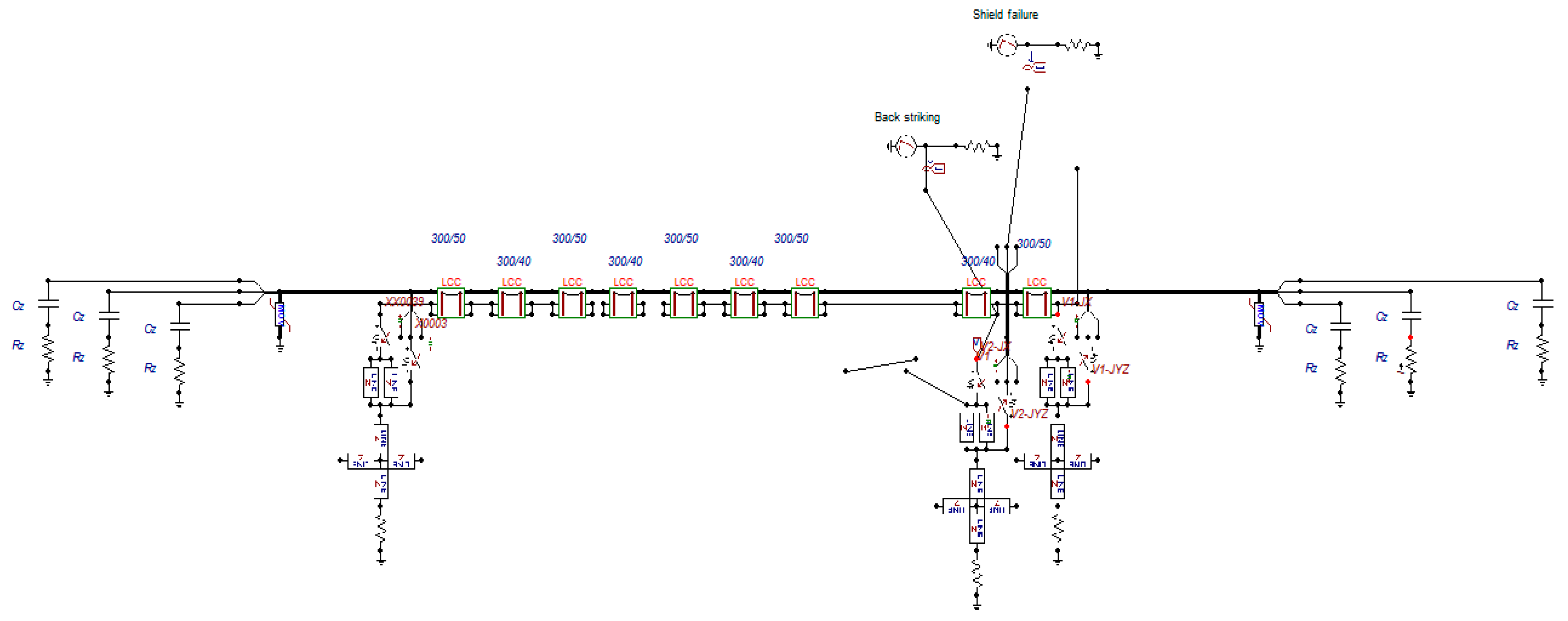
19]. These two lightning over-voltages can be calculated by the Electro-Magnetic Transient Program (EMTP). The simulation model is shown in
Figure 5.
From this simulation model, the following results were attained:
- (1)
Back striking: According to GB/T 50064-2014 [
20], the back striking lightning current of a 220 kV AC transmission line is 75~110 kA. In the simulation, if the back striking lightning current is 75 kA, then the maximum voltage on the parallel gap is 13 MV.
- (2)
Shield failure: Shield failure of the 220 kV tower is 16 kA, and the maximum voltage on the parallel gap is 885 kV in the simulation.
5.3. Lightning Over-Voltage Calculation of a 500 kV Ground Wire Insulator and Parallel Gap
There are also two lightning over-voltages on a 500 kV ground wire insulator and parallel gap separately caused by shield failure and back striking. From a simulation model similar to that in
Figure 5, the following results were obtained:
- (1)
Back striking: According to GB/T 50064-2014 [
20], the back striking lightning current of a 500 kV AC transmission line is 125~175 kA. In the simulation, if the back striking lightning current is 125 kA, the maximum voltage on the parallel gap is 15 MV.
- (2)
Shield failure: Similarly, the shield failure of a 500 kV tower is 25 kA, and the maximum voltage on the parallel gap is 1.36 MV in the simulation.
5.4. Capability Check of Parallel Gap in the Case of Lightning
In the case of lightning, the ground wire insulator and parallel gap should meet the requirements of reliable breakdown. It is known from the above calculation results that the voltage which the ground wire insulator and parallel gap can afford is 885 kV at least, even up to several MV in the case of 220 kV and 500 kV AC transmission lines suffering shield failure and back striking. The lightning impact discharge voltage of a gap distance between 70 mm and 80 mm is under 100 kV generally. Under this high lightning impulse voltage, a gap distance between 70 mm and 80 mm must be broken.
5.5. Simulation Method and Calculation Results of the Effects of Graded Insulation of OPGW on Lightning Protection Performance
This paper calculates the lightning trip-out rate of a UHV AC transmission line when OPGW uses different grounding modes and compares the results. Results are shown in
Table 4. In
Table 4, Approach 1 is OPGW being grounded at every tower, and Approach 2 is OPGW being grounded at one tower.
As shown in
Table 4, there is no effect when we change the grounding mode of OPGW, because the parallel gap of the insulator is mainly broken in the case of lightning impulse voltage.
6. The Influence of Grounding Modes of OPGW on Power Loss of a UHV AC Transmission Line
6.1. Calculation Method of Power Loss
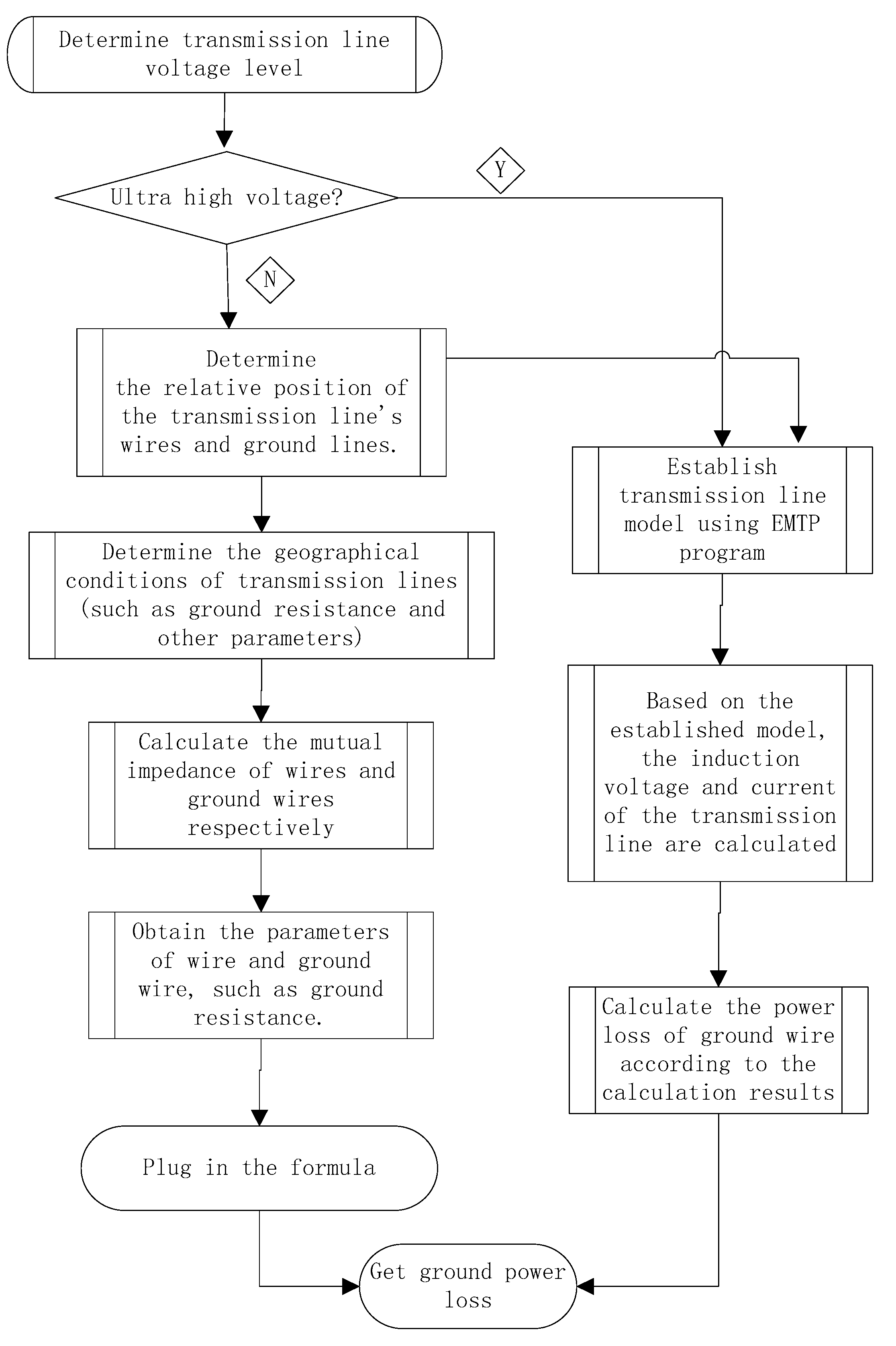
The power loss of the ground wire was calculated using the Electro-Magnetic Transient Program (EMTP) based on a simulation; the calculation method is shown in
Figure 6.
6.2. Results of Power Loss
Take the UHV AC from north Zhejiang to Fuzhou as an example. The results of induced current on the UHV AC overhead ground wire are shown in
Table 5. As shown in
Table 5, the induced current for OPGW grounded at every tower is much larger than that for OPGW with graded insulation and single-point grounding.
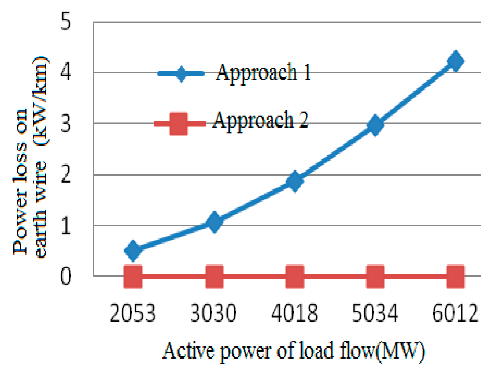
There is a relationship between the power loss of the ground wire and the transmission power of the line. Such a relationship is shown in
Table 6 and
Figure 7. When the transmission power is the same, the power loss from being grounded at every tower is much larger than that from graded insulation. When OPGW uses graded insulation, power loss can be reduced by over 99% when compared with another type as shown in
Table 6.
7. Conclusions
In order to satisfy the demands of DC de-icing of an optical fiber composite overhead ground wire (OPGW) and solve questions such as those relating to circulating current loss and the liability of suffering from lightning stroke and breaking, the grounding method of OPGW must be changed from the current commonly used method of being grounded at every tower to being grounded at one tower.
OPGW would be insulation reconstructed and be connected with the tower by a ground wire insulator, which should be equipped with a protective discharge clearance. The recommended value of this discharge clearance is from 70 to 80 mm, which was calculated and experimentally researched. The lightning impulse discharge voltage of such a 70 to 80 mm clearance is generally not more than 100 kV. However, as the transmission line is struck by lightning, over-voltage on the insulator and clearance is 885 kV at least, even up to a few MV. The clearance can be broken down reliably to ensure the safety of the insulator. Changing the grounding mode of OPGW has no effect on lightning performance.
As the grounding mode of OPGW is changed from being grounded at every tower to graded insulation and being grounded at one tower, the induced current of the ground wire can be reduced to below 1 A and power loss can be reduced to below 1 W/km, a reduction of over 99%.


