Article

Power and Voltage Control for Single-Phase Cascaded H-Bridge Multilevel Converters under Unbalanced Loads

1
College of Electrical Engineering, Guangxi University, Nanning 530004, China
2
Liuzhou Power Supply Bureau, Gxuangxi Power Grid Corporation, Liuzhou 545005, China
3
Electric Power Research Institute, Guangxi Power Grid Corporation, Nanning 530023, China
*
Author to whom correspondence should be addressed.
Energies 2018, 11(9), 2435; https://doi.org/10.3390/en11092435
Submission received: 31 August 2018 / Revised: 9 September 2018 / Accepted: 11 September 2018 / Published: 14 September 2018
(This article belongs to the Special Issue Design and Control of Power Converters 2019)

Abstract

:
The conventional control method for a single-phase cascaded H-bridge (CHB) multilevel converter is vector (dq) control; however, dq control requires complicated calculations and additional time delays. This paper presents a novel power control strategy for the CHB multilevel converter. A power-based dc-link voltage balance control is also proposed for unbalanced load conditions. The new control method is designed in a virtual αβ stationary reference frame without coordinate transformation or phase-locked loop (PLL) to avoid the potential issues related to computational complexity. Because only imaginary voltage construction is needed in the proposed control method, the time delay from conventional imaginary current construction can be eliminated. The proposed method can obtain a sinusoidal grid current waveform with unity power factor. Compared with the conventional dq control method, the power control strategy possesses the advantage of a fast dynamic response. The stability of the closed-loop system with the dc-link voltage balance controller is evaluated. Simulation and experimental results are presented to verify the accuracy of the proposed power and voltage control method.

1. Introduction

Multilevel converters have gained increasing attention as of late. Commonly used multilevel converters include cascaded H-bridge (CHB), flying capacitor, and neutral-point-clamped converters [1]. Among these, the CHB converter has advantages of simple implementation, high reliability, and low harmonics [2], hence, it has been widely researched in academia and industry, particularly in relation to static synchronous compensators [3], solid-state transformers [4], and active power filters [5].
Many control schemes have been proposed to enable the pulse width modulation (PWM) converter to achieve a high power factor and near-sinusoidal grid current [6]. These strategies can be broadly classified into two categories: direct power control (DPC) and direct current control (DCC).
DPC was originally proposed by Ohnishi [7], whose method directly controls the active and reactive power of the PWM converter using three-phase instantaneous power theory. Compared with DCC, DPC has advantages of simple structure, fast dynamic response, high efficiency, and wide applicability [8]. Currently, many advanced DPC strategies have been proposed, such as predictive DPC (P-DPC) [9], deadbeat DPC [10], and slide-mode DPC [11]. In the single-phase PWM converter system, instantaneous power estimation is more complicated than in the three-phase system, which limits the development of DPC schemes in single-phase systems [12].
DCC methods have been frequently used with the PWM converter. The most commonly used DCC method utilizes vector control theory (dq control) [13,14,15,16]. Coordination transformation is needed in dq control to change the ac signals into dc signals [17]. The grid voltage phase angle is essential in the coordinate transformation; therefore, a phase-locked loop (PLL) is employed to synchronize the output voltage with the grid voltage vector [18]. To accurately obtain the information on the grid voltage including the amplitude and phase angle, some advanced PLLs have been proposed, such as hybrid filtering technique-based PLL [19], grid sequence separator PLL [20], frequency-fixed SOGI-based PLL [21], and repetitive learning-based PLL [22]. However, the computational complexity of coordinate transformation and PLL increases the calculation burden of the embedded processor like the digital signal processor (DSP) [23]. Therefore, the development of a convenient control method without PLL or coordination transformation is appealing. Recently proposed control methods of the CHB converter are based on model-predictive control (MPC) [24,25]. However, three major problems arise in the MPC scheme used for the CHB converter. First, the calculation burden persists in the MPC method because the number of switching states increases exponentially as more H-bridges are added [26]. The second one is the MPC system sensitiveness problem like sensitive to the parameter [27]. The third problem is that under unbalanced load conditions, the MPC strategy cannot provide a proper control function [28].
It is exceedingly difficult to implement the dq control scheme in the single-phase CHB converter system; imaginary orthogonal current and voltage signals must be created for coordinate transformation (αβ to dq) because only one physical axis is accessible [29]. In dq control, the imaginary orthogonal current signal is essential in acquiring the dc current signals id and iq for the inner current loop [30]. Thus, an imaginary current construction module is required to produce the imaginary orthogonal current signal [31]. Although the performance of conventional imaginary current construction under the steady state is mostly acceptable, the time delay tends to slow down the system dynamic response and result in further distortion [32,33].
The control scheme performance of the CHB converter in the single-phase system depends on two key factors: sinusoidal grid current waveform with unity power factor and balanced dc-link voltages [34,35]. Therefore, the CHB multilevel converters need a control method to balance the dc-link voltages, especially when the dc-side loads are unbalanced. In [36,37], the dc-link voltages were controlled using individual capacitor voltage controllers. In [38], the presented voltage balance control method uses a weighting factor to adjust the dc-link voltages. In [39], two voltage-balancing techniques were presented, allowing for much more efficient regulation of dc-link voltages. However, these voltage balanced control methods are all based on ac voltage reference duty cycle regulation; a power-based dc-link voltage balance controller has not been analyzed in detail.
In the conventional dq control strategy, the current calculation is complicated and additional time delay is required. For optimization purposes, a power control method without coordinate transformation, PLL or conventional imaginary current construction is introduced and applied to control the single-phase CHB multilevel converter system. Moreover, a power-based dc-link voltage balance control scheme is presented to make the proposed power control strategy available under unbalanced load conditions. This power and voltage control method can achieve a sinusoidal grid current waveform and balanced dc-link voltages. Several experimental tests were conducted to compare dynamic responses of the presented control scheme with those of the classical dq control method. The proposed voltage balance controller is verified as well.
The remainder of this paper is organized as follows: in Section 2, principles of the proposed control scheme and dc-link voltage balance controller are discussed, and the stability of the closed-loop system with the dc-link voltage balance controller is evaluated. Section 3 presents the simulation results. Experimental results are addressed in Section 4. The proposed control method is discussed in Section 5. Finally, relevant conclusions are drawn in Section 6.

2. Control Method Principles

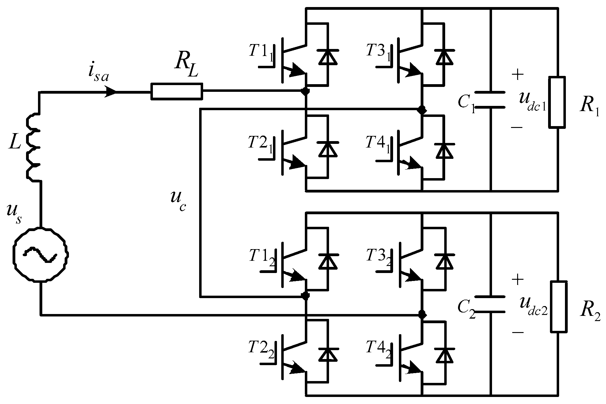
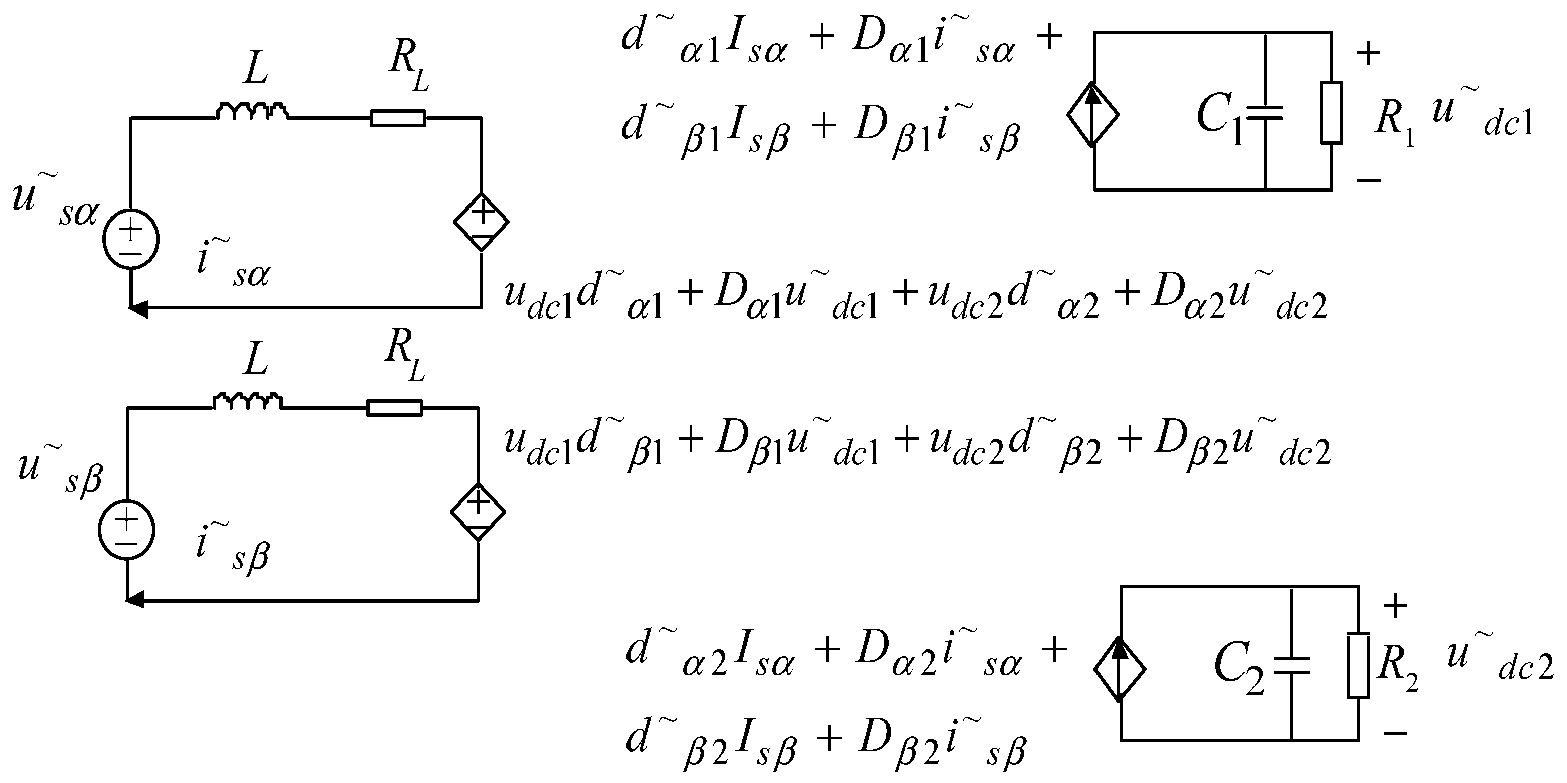
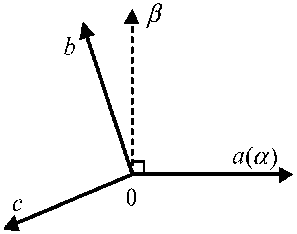
2.1. Model of the Cascaded H-Bridge Multilevel Converter

Figure 1 presents the topology of a two-cell CHB system in which us is the grid voltage, isa is the grid current, uc is the ac side voltage, L and RL denote the filter inductor and line resistance, respectively,. udc1 and udc2 represent the dc-link voltages of the first and second H-bridge, and udc_sum is the total dc-link voltage (udc1 + udc2). R1 and R2 are the resistive loads connected to the dc side of each H-bridge.
The mathematical model of the CHB converter is as follows:
{ L d i s a d t = u s u c R L i s a u d c _ s u m = u d c 1 + u d c 2
To simplify analysis of system stability, according to Equation (1), a small-signal model of the stationary reference frame (αβ frame) was built, as illustrated in Figure 2. Here, u equals us, and u is the orthogonal signal of us; u~ and u~ represent the small-signal ac variation of u and u; u~dc1 and u~dc2 denote the small-signal ac variation of udc1 and udc2; i equals isa, and i is the orthogonal signal of isa; i~ and i~ represent the small-signal ac variation of i and i; I and I stand for the quiescent operating point of i and i; Dα1, Dα2, Dβ1, and Dβ2 are the duty cycles of the first and second H-bridge; and d~α1, d~α2, d~β1, and d~β2 represent the small-signal ac variation of Dα2, Dβ1, and Dβ2.

2.2. Principle of the Proposed Power Control Method

The main function of CHB multilevel converter is to obtain active power and reactive power from the grid to satisfy load needs. For the CHB converter, the essence of controlling the grid current as well as the dc-link voltage is control of the input and output power. By rapidly and effectively controlling the active and reactive power, the converter can achieve strong dynamic and static characteristics.
In the three-phase CHB converter system, the active power p and reactive power q can be described as:
[ p q ] = [ u s α u s β u s α u s β ] [ i s α i s β ]
where u* = u, u* = −u.
Only one phase physical variable is available in the single-phase CHB converter system; a second-order generalized integrator (SOGI) block is needed to introduce the imaginary signal. The virtual αβ stationary reference frame is depicted in Figure 3, the α-axis coincides with the a-axis, and the β-axis is orthogonal to the α-axis.
In the single-phase CHB converter system, p and q can be described as follows:
[ p q ] = 1 3 [ u s α u s β u s α u s β ] [ i s α i s β ]
p* and q* are defined as the active power and reactive power reference, respectively; i* and i* represent the current reference.
Equations (4) and (5) are shown as follows according to Equation (3), and the coefficient calculation of the proposed power control is shown in Equation (6):
[ i s α i s β ] = 3 u s α u s β u s α u s β [ u s β u s β u s α u s α ] [ p q ]  
[ i s α i s β ] = [ 3 u s β u s α u s β u s α u s β p + 3 u s β u s α u s β u s α u s β q 3 u s α u s α u s β u s α u s β p + 3 u s α u s α u s β u s α u s β q ]  
{ k 1 = 3 u s β u s α u s β u s α u s β k 2 = 3 u s β u s α u s β u s α u s β  
If the grid voltage is sinusoidal, then the result of u * u* + u*sα * u* is constant; p* is controlled by the outer power loop; q* is constant because it is given directly; therefore the frequency and phase of the current references i and i are consistent with the instantaneous grid voltage, and the real-time tracking can be achieved. Notably, only i* is used as the current reference, because the CHB multilevel converter is used on a single-phase system.

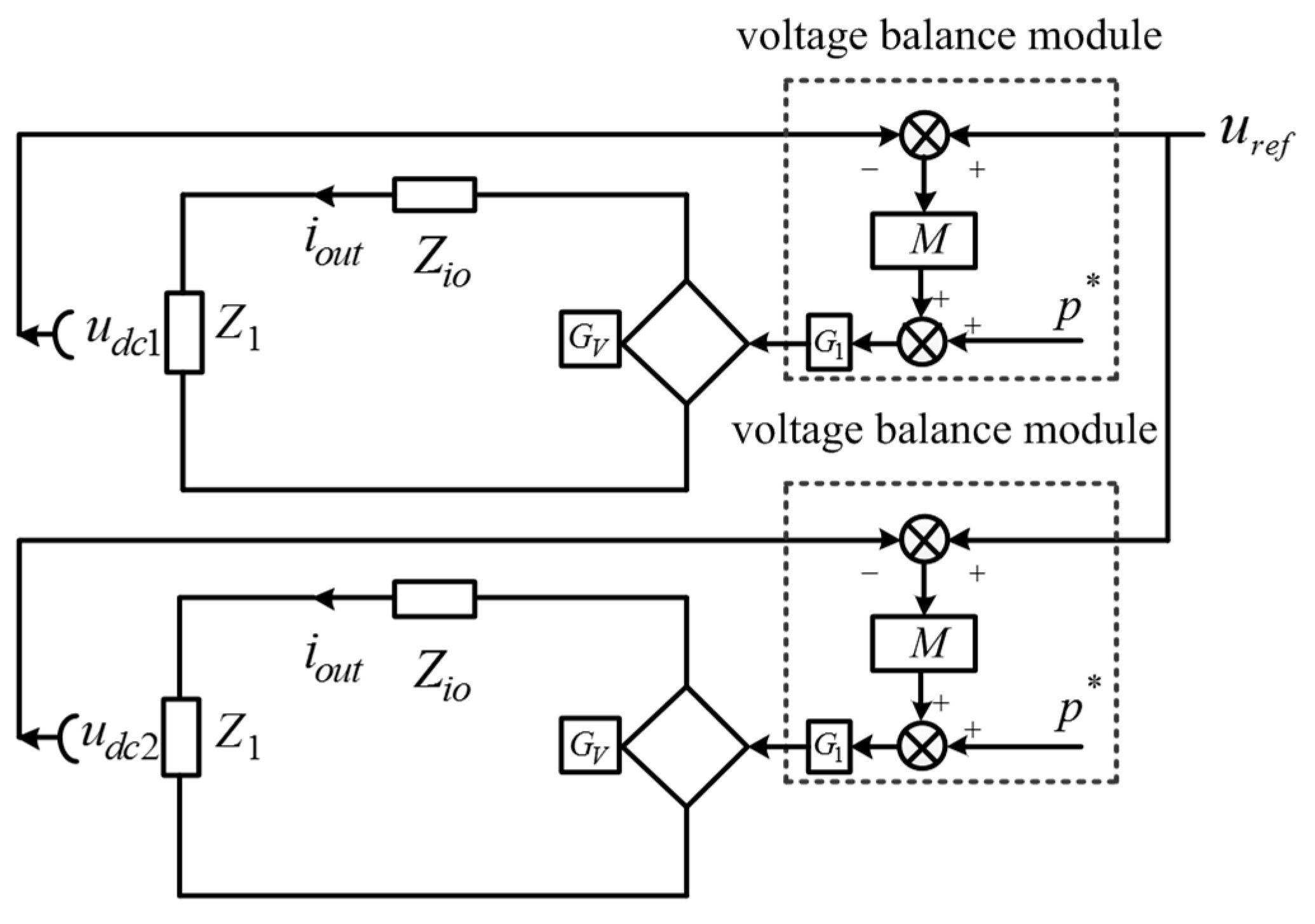
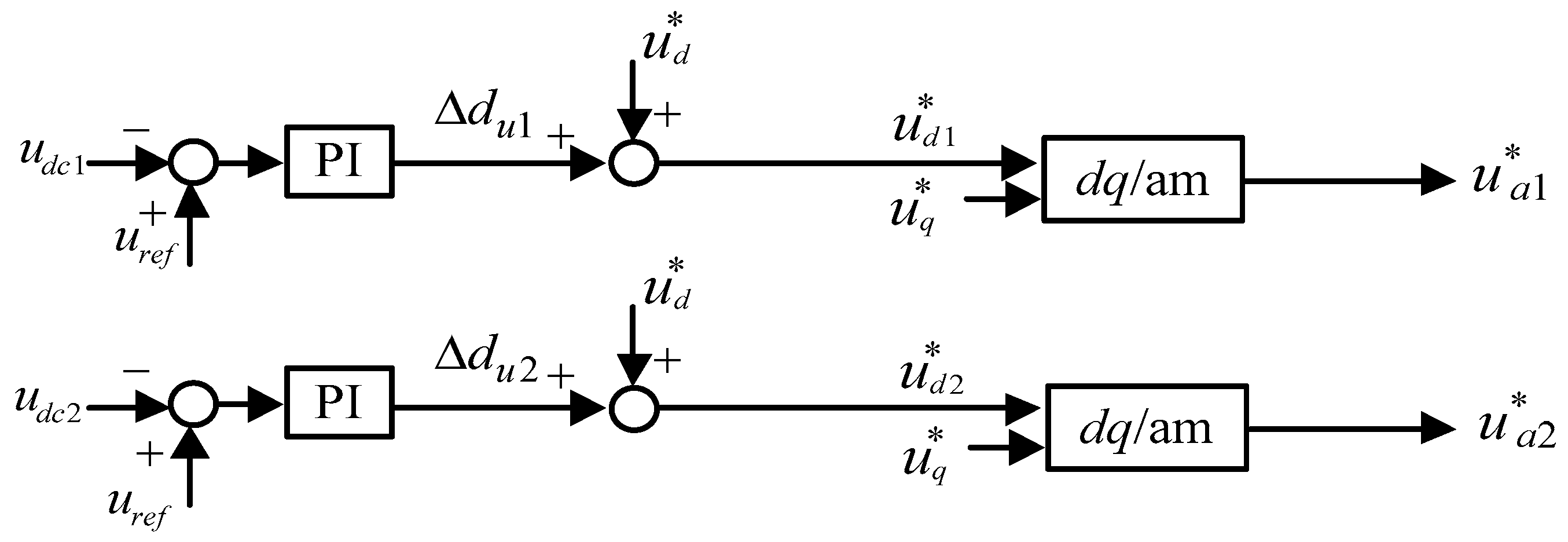
2.3. Presentation of Proposed Dc-Link Balance Controller

Figure 4 presents the conventional dc-link voltage balance controller. In this approach, the duty cycles of each ac voltage reference u*a1 and u*a2 are modified separately to keep the voltages balanced, and the scheme is suitable for the dq method. A power-based dc-link voltage balance controller adjusting the ac current reference duty cycle is introduced in this paper to regulate the individual H-bridge dc-link voltage.
If the dc-link voltage of each H-bridge is unbalanced (mainly via load imbalance), then the power of these H-bridges becomes uneven. To keep the dc-link voltage balanced, the uneven power should be extracted from the grid. ∆dp1 and ∆dp2 are used as the compensation values to eliminate uneven power. ∆dp1 and ∆dp2 are calculated by the voltage balance controller:
{ Δ d p 1 = ( K p + K i s ) ( u r e f u d c 1 ) u d c 1 Δ d p 2 = ( K p + K i s ) ( u r e f u d c 2 ) u d c 2
where Kp and Ki represent the proportional and integral coefficient of the proportional-integral (PI) controller, respectively, and uref is the voltage reference of every H-bridge cell.
The presented voltage balance controller is shown in Figure 5, which modifies the duty cycles of each ac current reference i*sa1 and i*sa2 individually to reduce the dc voltage imbalance. The current reference for each H-bridge can be calculated according to Equations (8)–(10):
{ i s α 1 = Δ d i s a 1 + i s α i s α 2 = Δ d i s a 2 + i s α
{ i s α 1 = Δ d p 1 ( k 1 + k 2 ) + p k 1 + q k 2 i s α 2 = Δ d p 2 ( k 1 + k 2 ) + p k 1 + q k 2
{ i s α 1 = k 1 ( Δ d p 1 + p ) + k 2 ( Δ d p 1 + q ) i s α 2 = k 1 ( Δ d p 2 + p ) + k 2 ( Δ d p 2 + q )

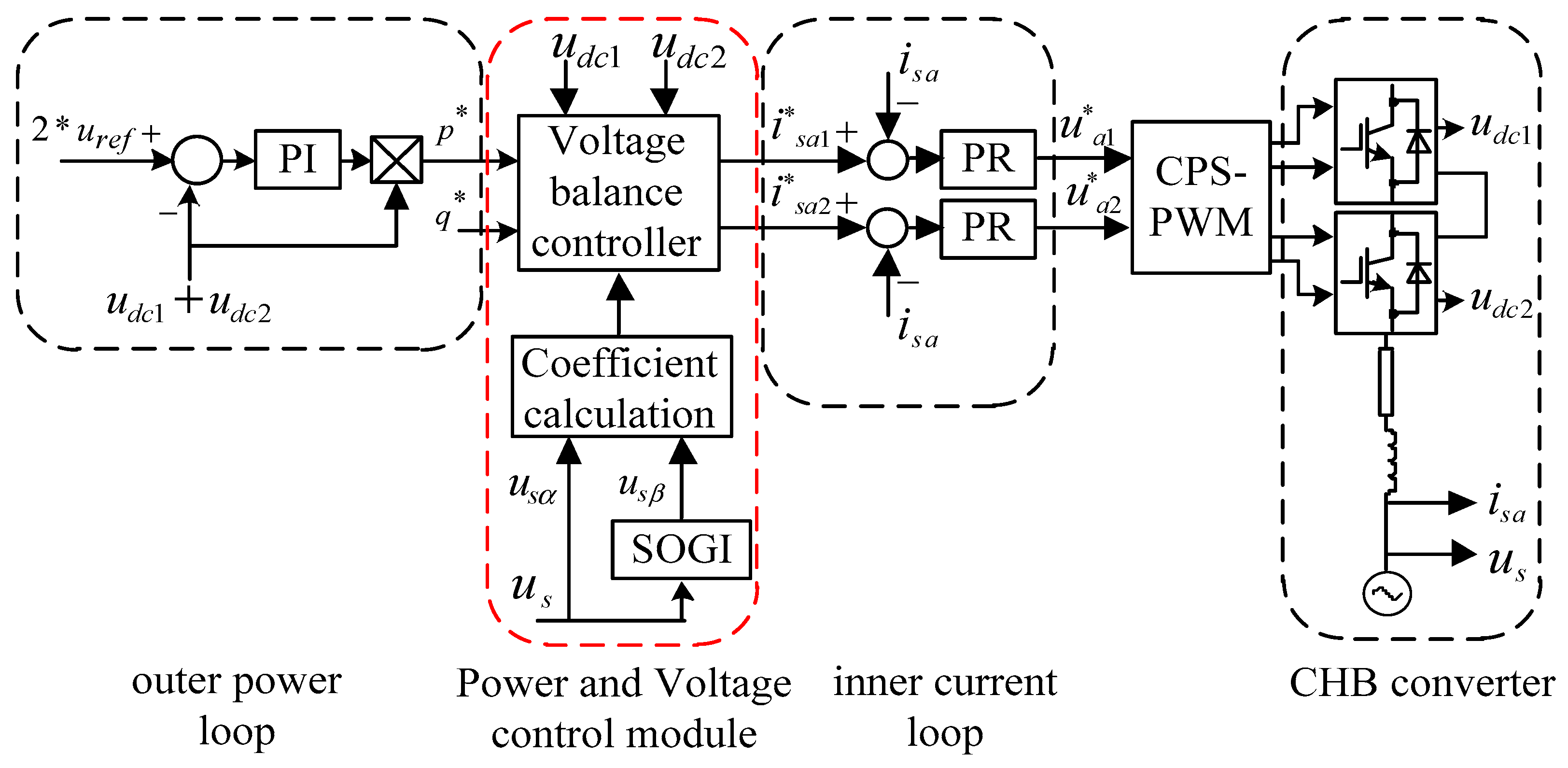
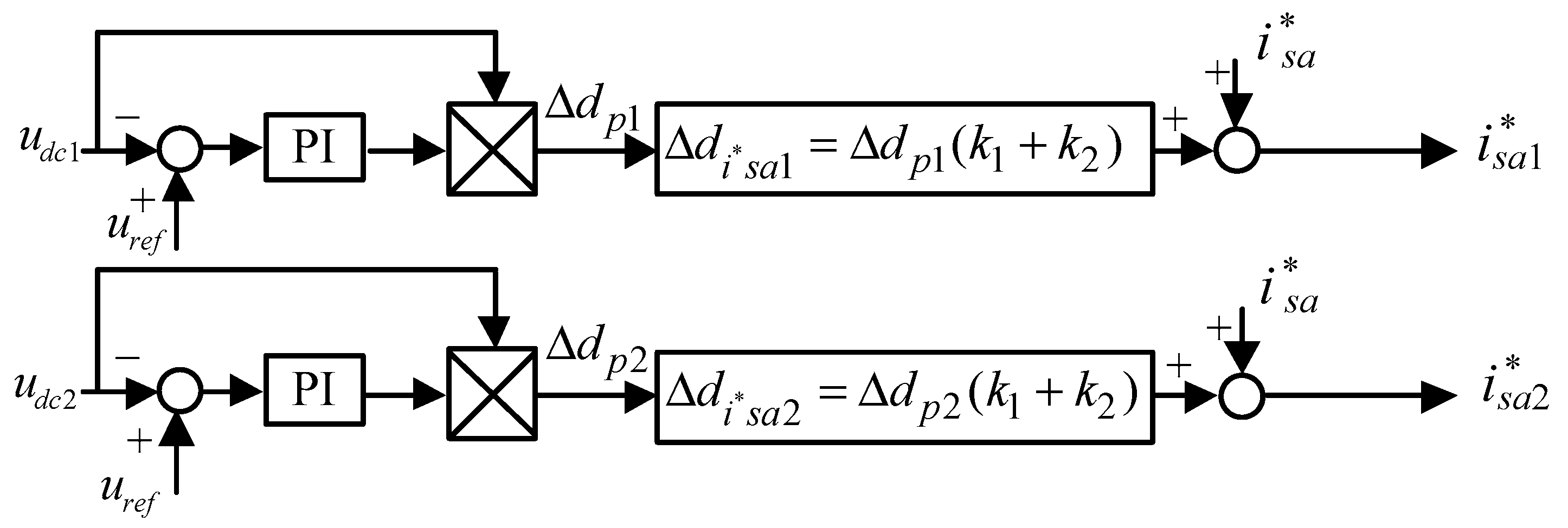
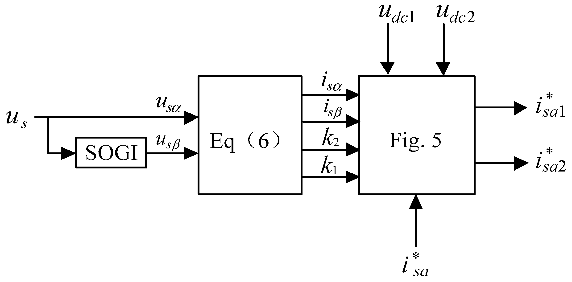
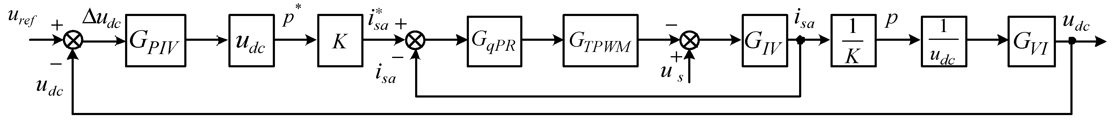
2.4. Proposed Power Control of the Cascaded H-Bridge Multilevel Converter

The overall control topology of the proposed control method is depicted in Figure 6. The main idea of the proposed control is to obtain command signals in the orthogonal αβ frame; as such, the dc-link voltages can be balanced.
The control system is formed as a double closed-loop control structure using the inner current loop and the outer power loop.
The inner current loop is implemented in the orthogonal αβ frame. Compared with classical single-phase dq schemes, the current calculation of the proposed control method is simpler because no coordinate transformation, PLL, or conventional imaginary current construction is needed. However, the current references i*sa1 and i*sa2 are ac variables. To track the current references with zero error in the stationary frame and achieve high tracking accuracy when the grid frequency fluctuates, rather than relying on conventional PI controllers or a repetitive controller [40], proportional-plus-resonant (PR) controllers are utilized in the current loop.
As for the outer power loop, a PI controller is used to adjust the total dc-link voltage udc_sum (udc1 + udc2). The active power p* is generated by multiplying the output of the PI controller by the total dc-link voltage udc_sum. Reactive power reference q* is given directly.
The detailed control topology of the power and voltage control module is shown in Figure 7. Current reference i*sa1 of the first H-bridge and i*sa2 of the second H-bridge are acquired through the dc-link voltage balance control block; these current references are controlled independently. Deviation values between the grid current isa and the current references are input into the PR regulators separately, and the modulation voltage signals u*a1 and u*a2 are generated for the first and second H-bridge. Carrier phase-shifted PWM (CPS-PWM) technology is adopted to generate five-level voltage, achieving multi-level modulation. Furthermore, if the reactive power reference q* is set to zero, then a unity power factor can be achieved.

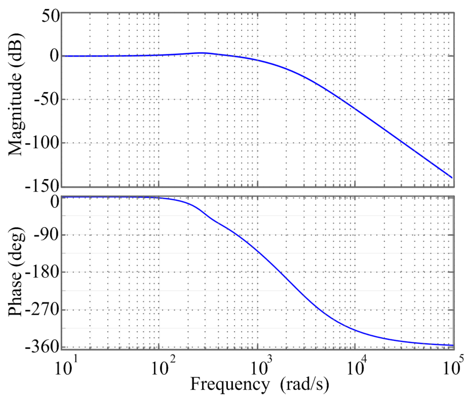
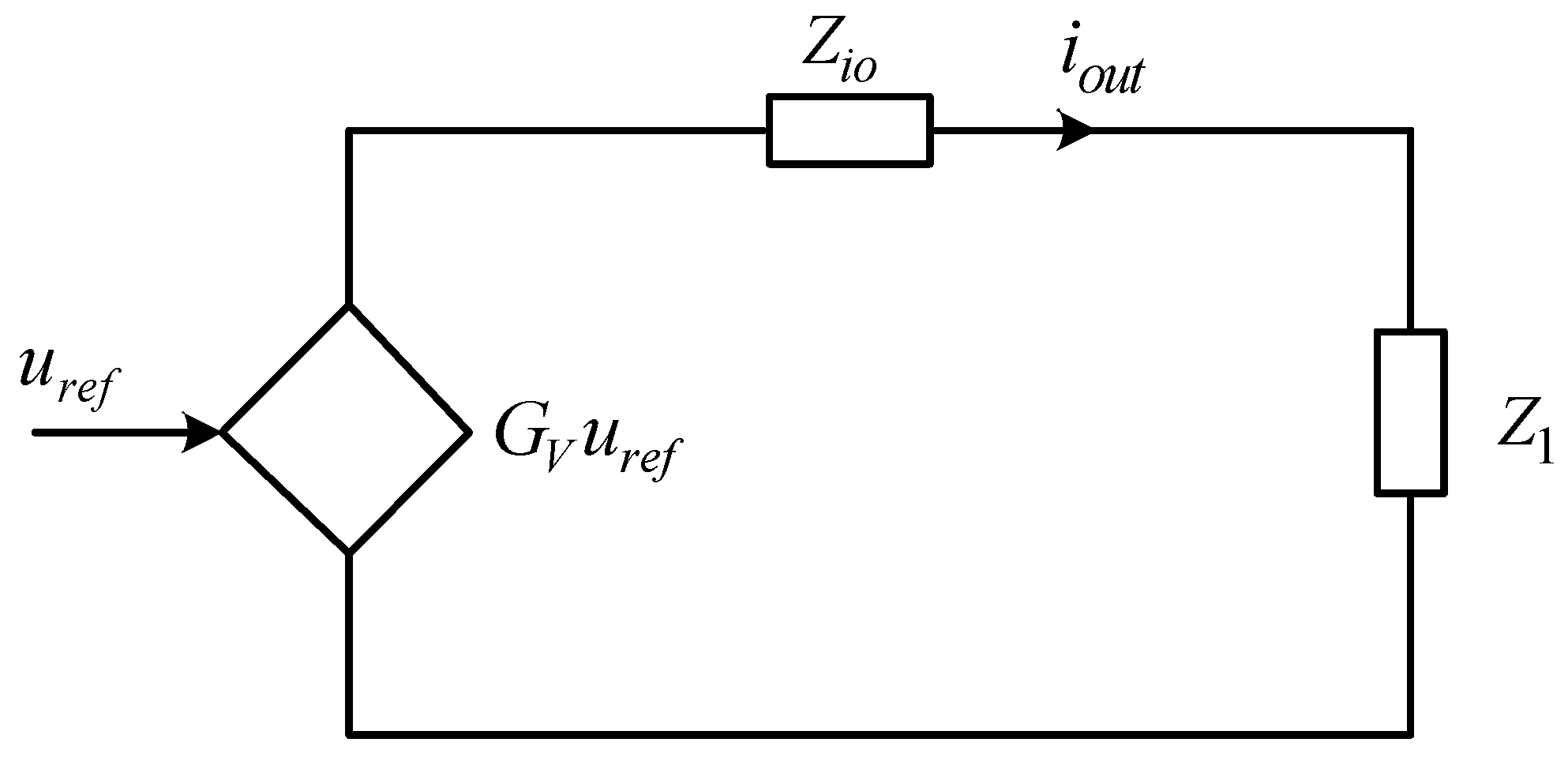
2.5. Stability Analysis of the Power and Voltage Control Scheme

Assume that the parameters of the H-bridges are identical, such that the dc-link voltage udc1 = udc2 = udc. The double-loop control diagram presented in Figure 6 can thus be transformed as illustrated in Figure 8. In Figure 8, GV is the voltage gain of CHB, GPIV is the voltage PI regulator, K is the conversion coefficient between p* and i*sa, GqPR is the current PR regulator, GTPWM is the transfer function of the PWM modulator, GIV is the transfer function of the voltage to output current i*sa, and GVI is the transfer function of the current to output voltage udc. GIV and GVI can be deduced from the small-signal model shown in Figure 2.
The closed-loop transfer function can be expressed as follows:
G V = G P I V G q P R G T P W M G I V G V I 1 + G P I V G q P R G T P W M G I V G V I
One bridge of the CHB converter can be simplified according to Figure 9 per Thevenin law. However, the dc-link voltage unbalance problem in CHB remains under the unbalanced load condition; therefore the voltage balance control module should be added. Figure 10 shows the Thevenin equivalent circuit with the dc-link voltage balance module, where Z1 is the load impedance, Zio is the impedance between the input and output of CHB, M is the gain of the voltage balance control module, G1 is the conversion coefficient of power to voltage, and iout is the output current. In this case G1 = 1/(GPIV * udc).
Taking the first H-bridge as an example:
G 1 [ p + ( u r e f u d c 1 ) M ] G V = Z i o u d c 1 Z 1 + u d c 1
u d c 1 = G V G 1 Z i o / Z 1 + 1 + G V G 1 M p + G V G 1 M Z i o / Z 1 + 1 + G V G 1 M u r e f
Because Z1 >> Zio, GG1M represents the gain in the basic double-loop controller with the dc-link voltage balance module from Equation (13); the Bode plot is shown in Figure 11. The amplitude margin is 12.7 dB, the cut-off frequency is 272 Hz, the phase margin is 105°, and the cross-over frequency is 78 Hz. All roots of (Zio/Z1 + 1 + GG1M) are on the left half-complex plane, ensuring stability of the system with the voltage balance control module.

3. Simulation Results

The CHB converter system shown in Figure 1 was modelled in the MATLAB/Simulink R2015a (MATLAB/Simulink R2015a, MathWorks, Natick, MA, USA) software environment to verify the power and voltage control scheme. The main system parameters used for simulation are shown in Table 1.

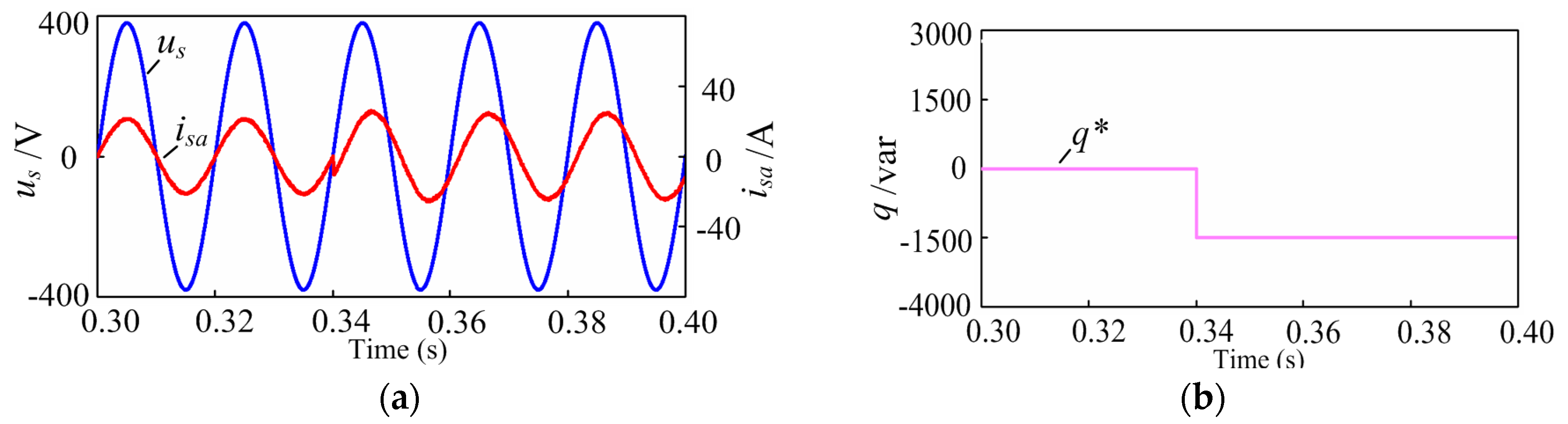
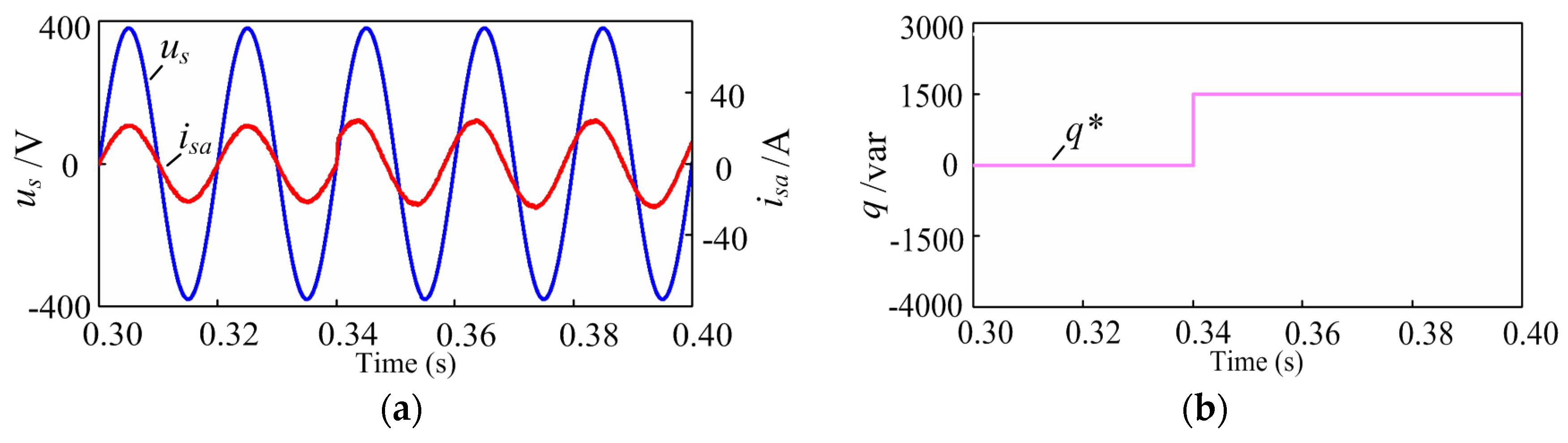
3.1. Proposed Power Control Scheme Simulation

Figure 12, Figure 13 and Figure 14 show the simulation results with unbalanced loads, where R1 = 10 Ω and R2 = 15 Ω. Figure 12a displays the grid voltage and grid current waveform in the steady state, revealing that the unity power factor was achieved.
Figure 12b shows the ac side five-level staircase voltage. Dynamic responses of the proposed method under sudden reactive power change conditions are shown in Figure 13 and Figure 14. In these, the active power reference p* is governed by the outer power loop, and the reactive power reference q* is changed from 0 to −1500 var and 0 to 1500 var at 0.34 s.

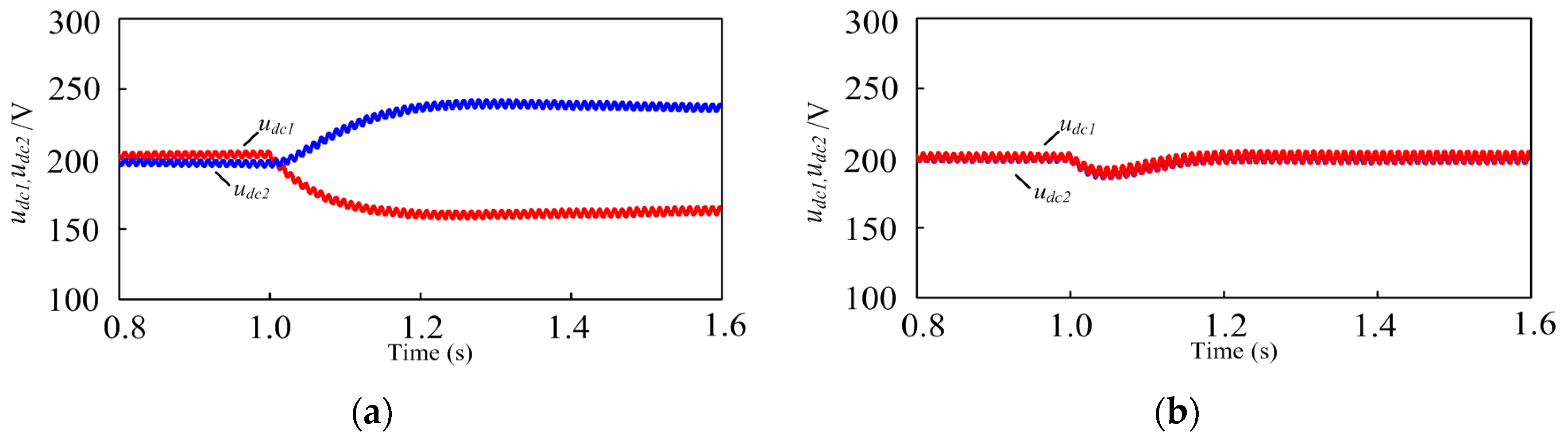
3.2. Power-Based Voltage Balance Control Simulation

In this simulation, the initial loads of two H-bridges were 15 Ω resistors. At 1.0 s, the resistor of the first H-bridge declined to 10 Ω. Two distinct cases were considered. In Figure 15a, the voltage balance control module was not utilized, and the dc-link voltages became different after the load change. The second H-bridge, whose resistor was unchanged, demonstrated higher dc-link voltage than the first H-bridge. Figure 15b shows the dc-link voltages with the voltage balance control method. Using the proposed voltage balance control module, the dc-link voltages returned to the initial value (200 V).

4. Experimental Results

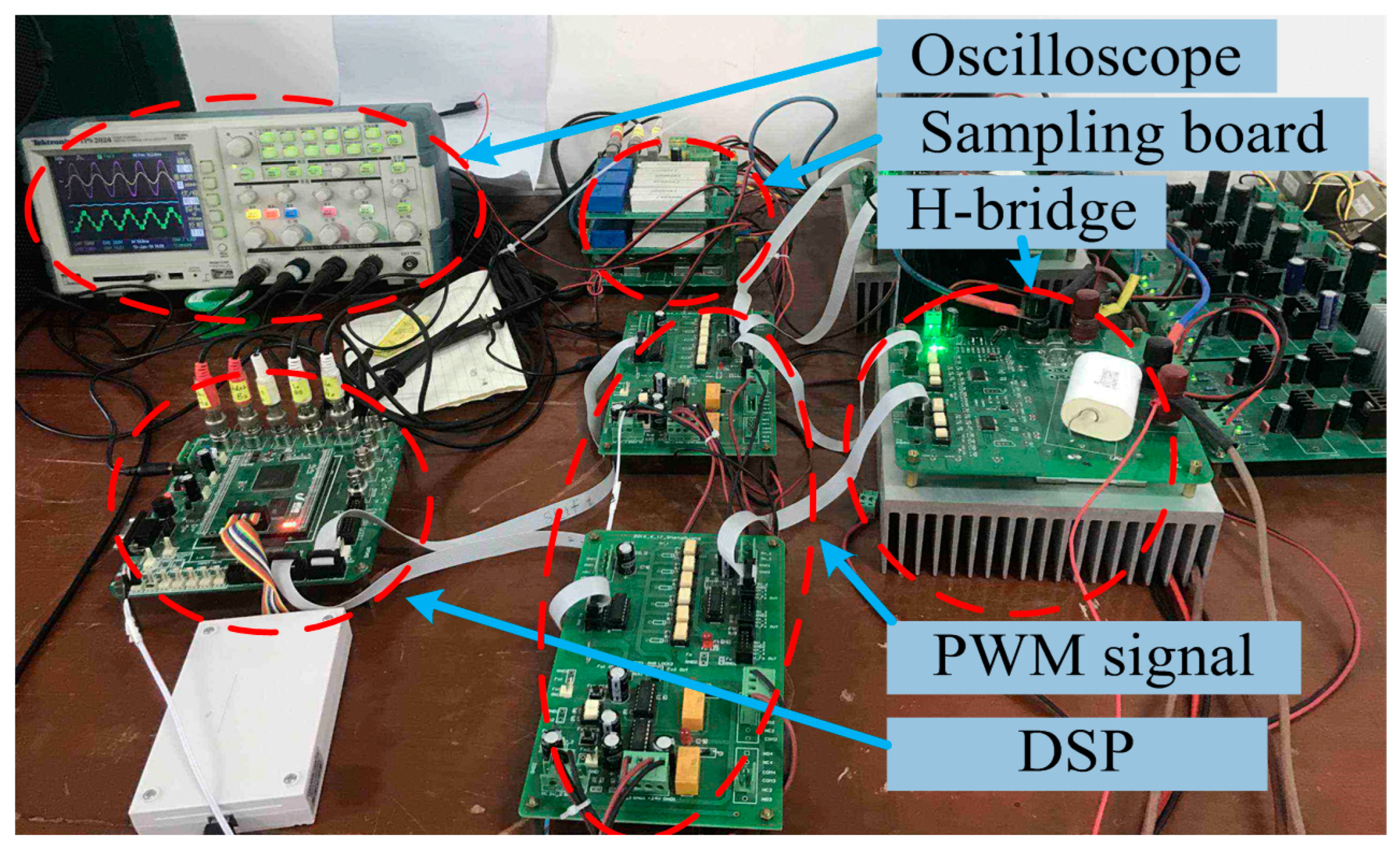
4.1. Experimental Prototype
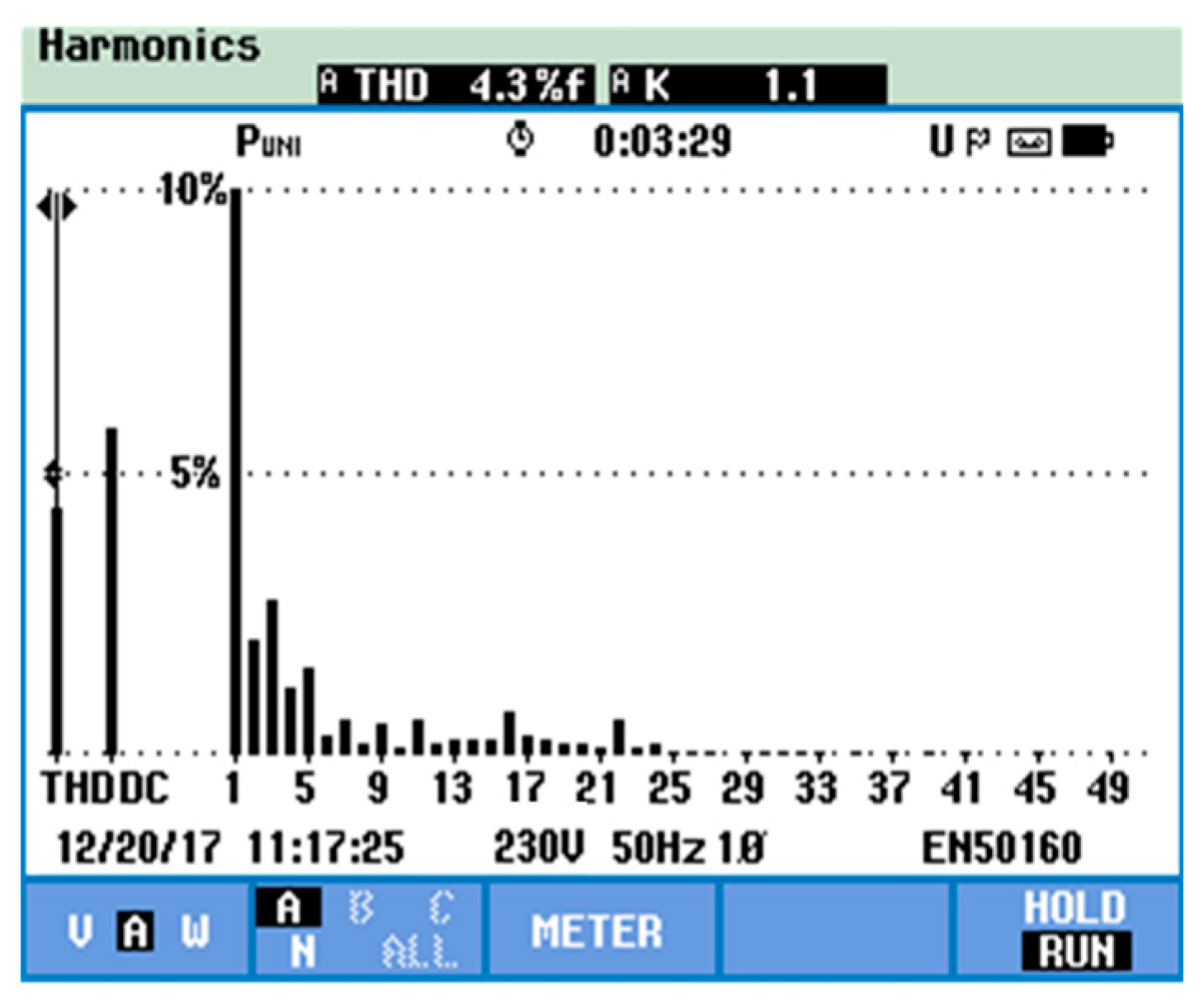
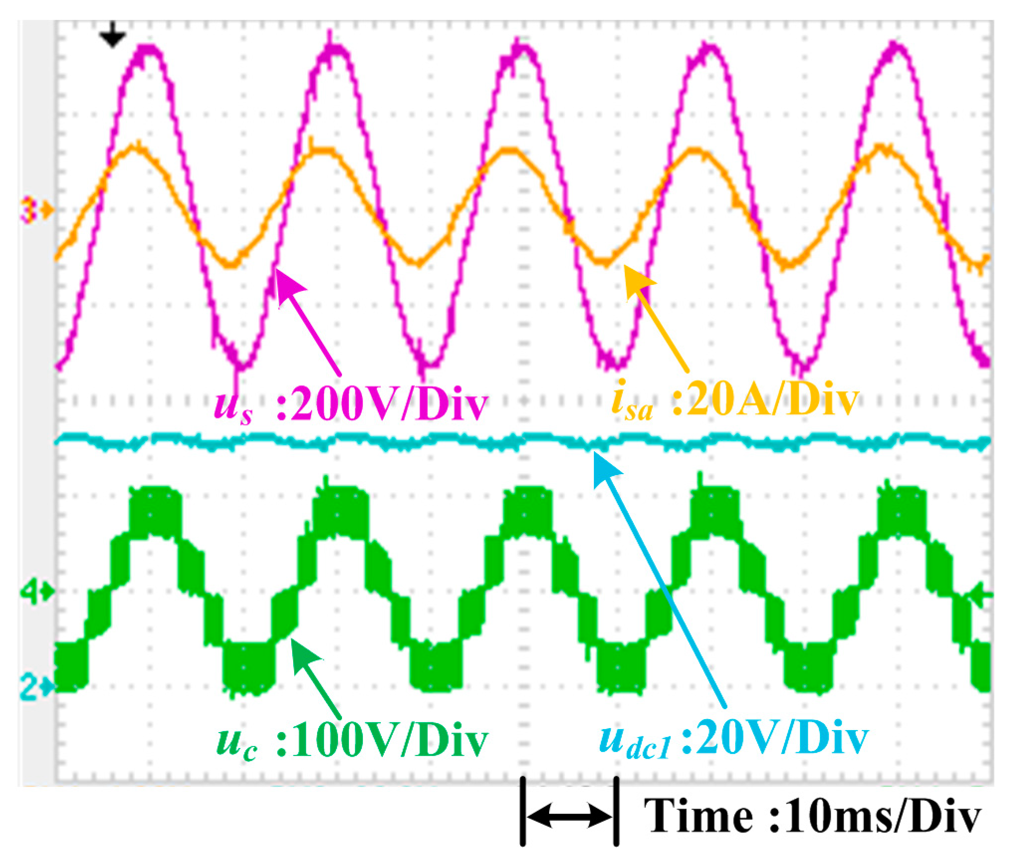
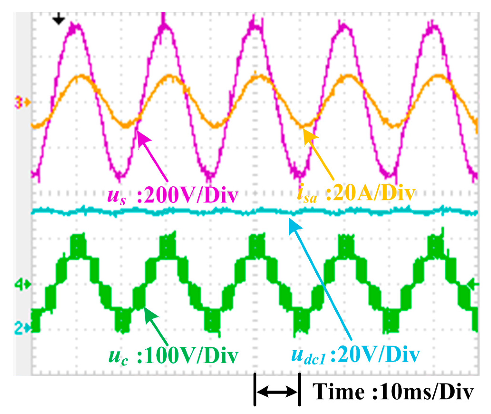
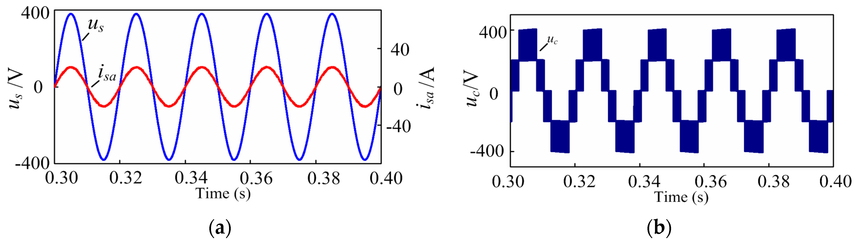
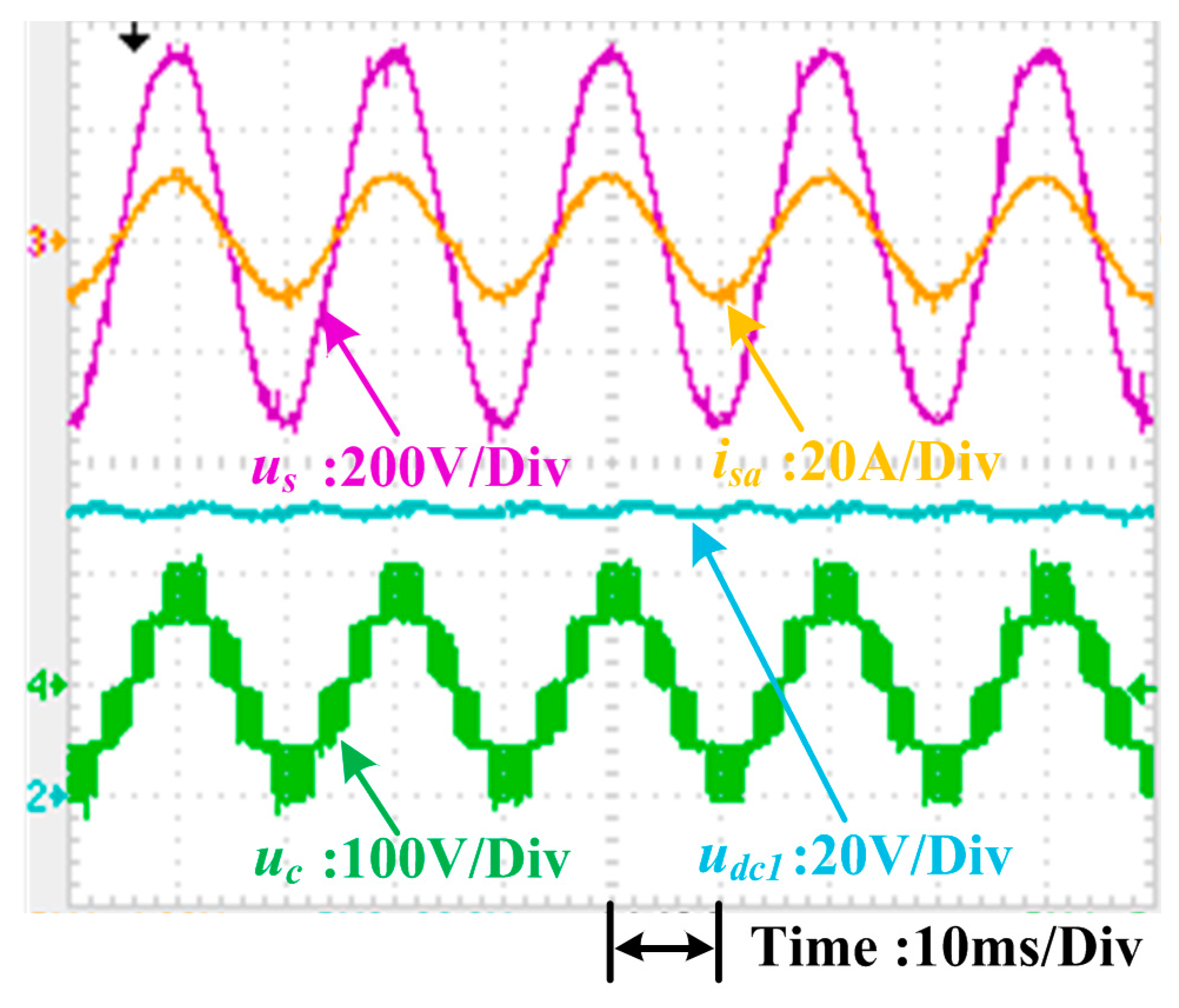
A single-phase five-level CHB converter experimental platform was adopted to validate the presented power and voltage control scheme, as shown in Figure 16.
Two H-bridge converters with serially connected inputs formed the ac side of the experimental setup. The dc output of each converter fed the loads. The converter was interfaced to the grid through a coupling transformer and a voltage regulator to ensure safety during the experiments. The secondary-side voltage of the regulator was set to 80 V (rms), while the dc-link voltage references udc1 and udc2 were set to 50 V. The grid voltage, grid current, ac side voltage, and dc-link voltages were measured using the outer high-performance hall sensors. A TMS320F28377D DSP processor board was utilized to implement the control algorithm. Measured voltage and current signals were fed back to the DSP processor board employing a built-in, 16-bit analog-digital conversion module. The power factor and total harmonic distortion (THD) of the grid current were measured via a Fluke 435 power quality analyzer.

4.2. Steady State

Figure 17 depicts the experimental waveforms of the grid voltage us (200 V/division), the grid current isa (20 A/division), the dc-link voltage of the first H-bridge udc1 (20 V/division), and the ac side voltage uc (100 V/division) for the proposed scheme in the steady state, where loads R1 and R2 in Figure 1 are 10 Ω and 15 Ω, separately. When the reactive power reference q* was set to zero, the grid current was in phase with the grid voltage, so the unity power factor was achieved. The THD of the grid current in the steady state was 4.3%, indicated in Figure 18. Moreover, this method was found to compensate for the reactive power: CHB converters can generate or absorb reactive power to the power grid when the reactive power reference is positive or negative. In Figure 19, the grid current was leading the grid voltage; thus, the CHB converter was generating reactive power to the system. In Figure 20, the grid current was lagging the voltage, and the CHB converter was absorbing reactive power from the system.

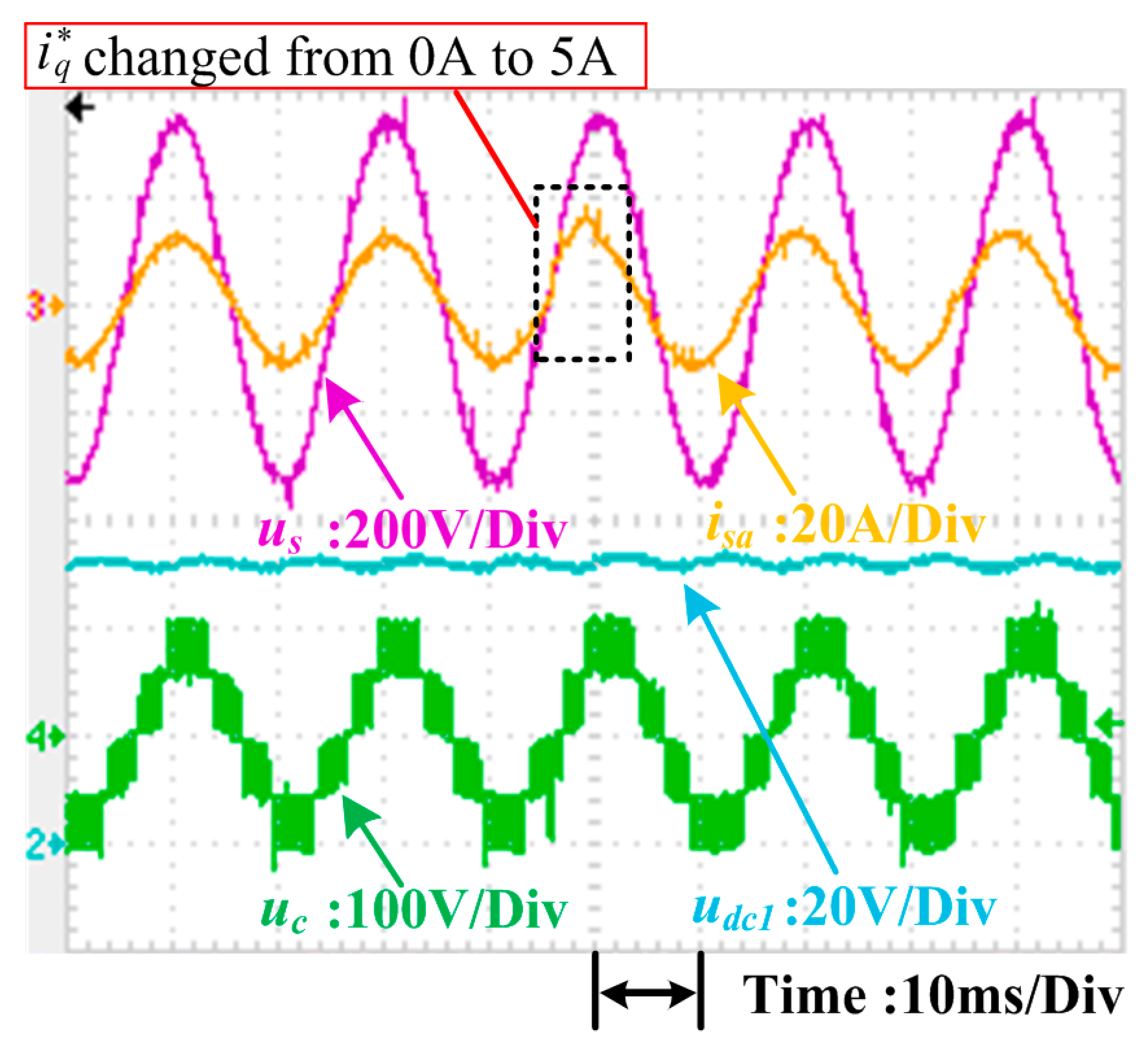
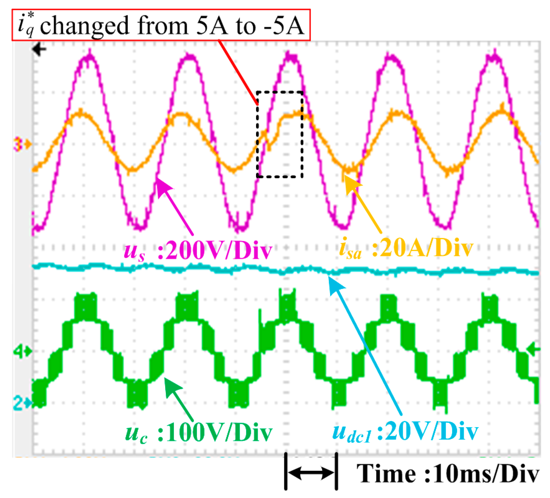
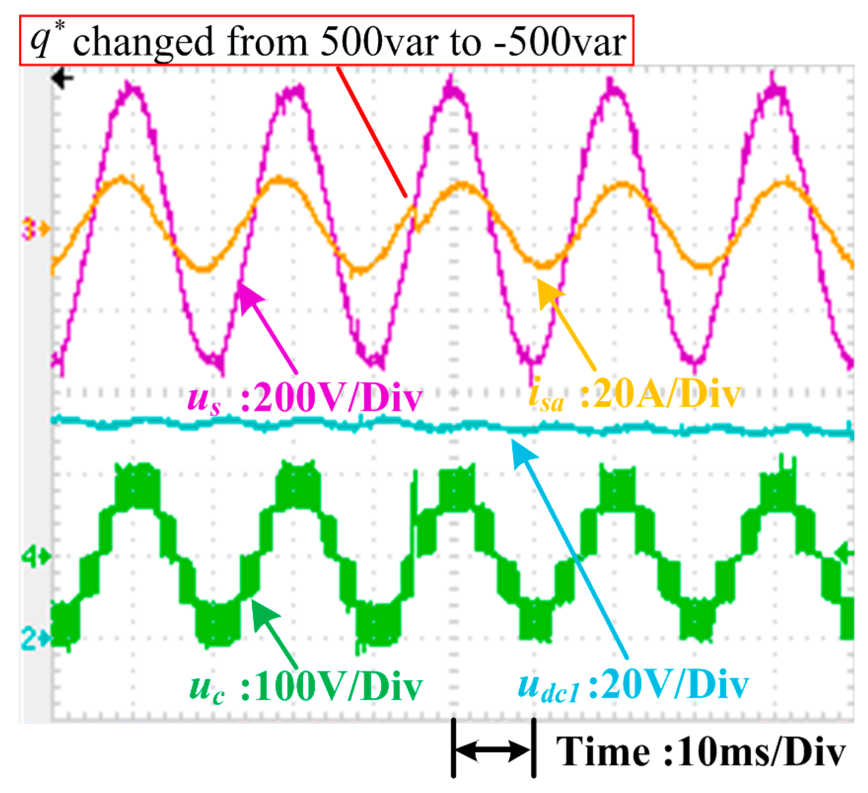
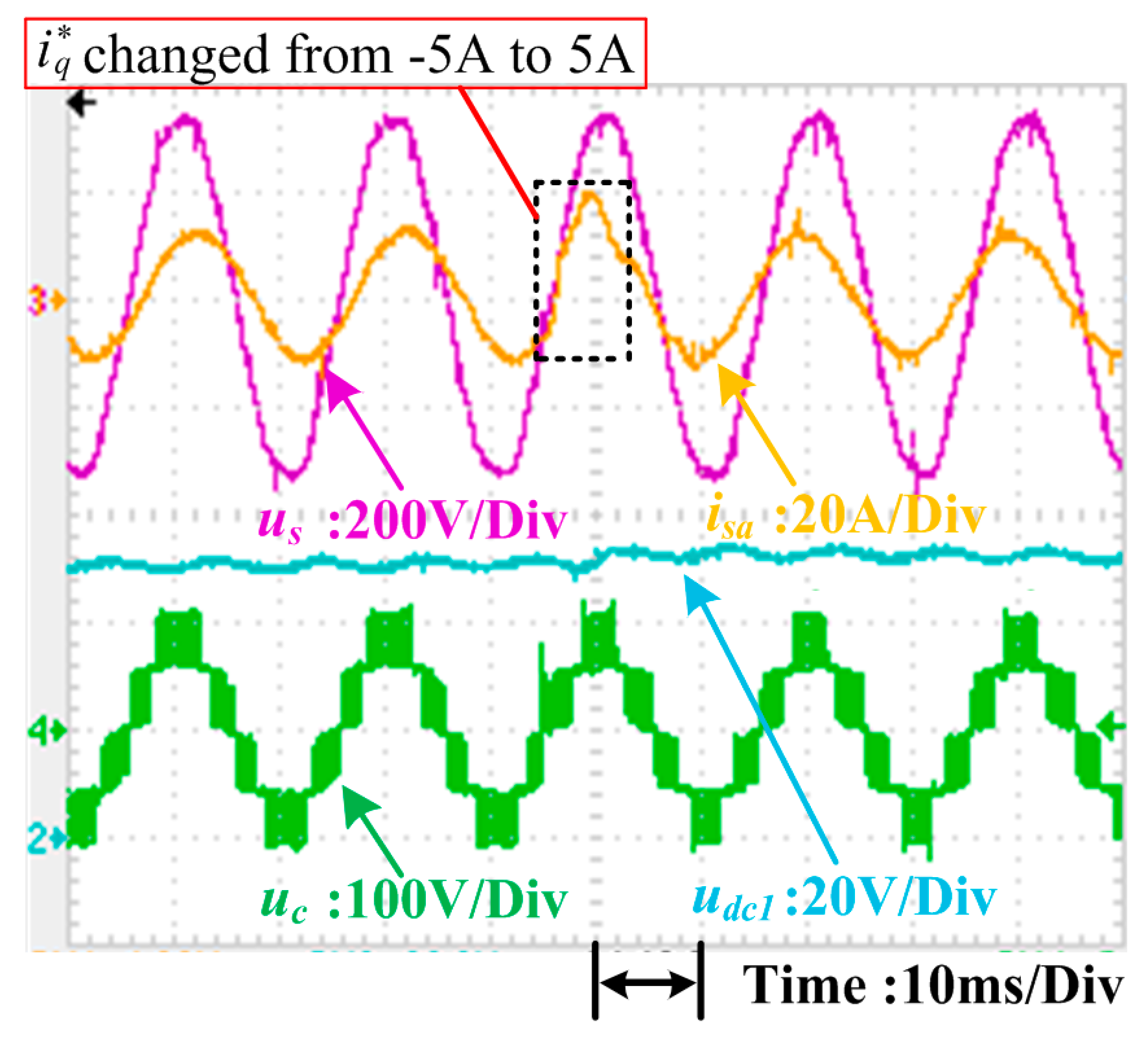
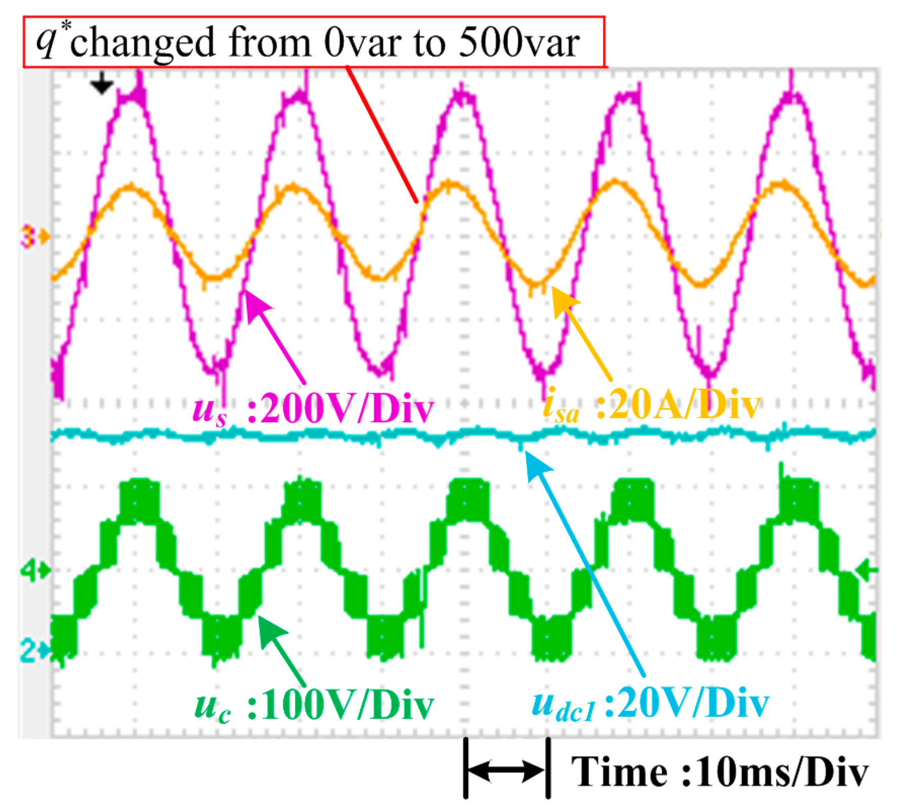
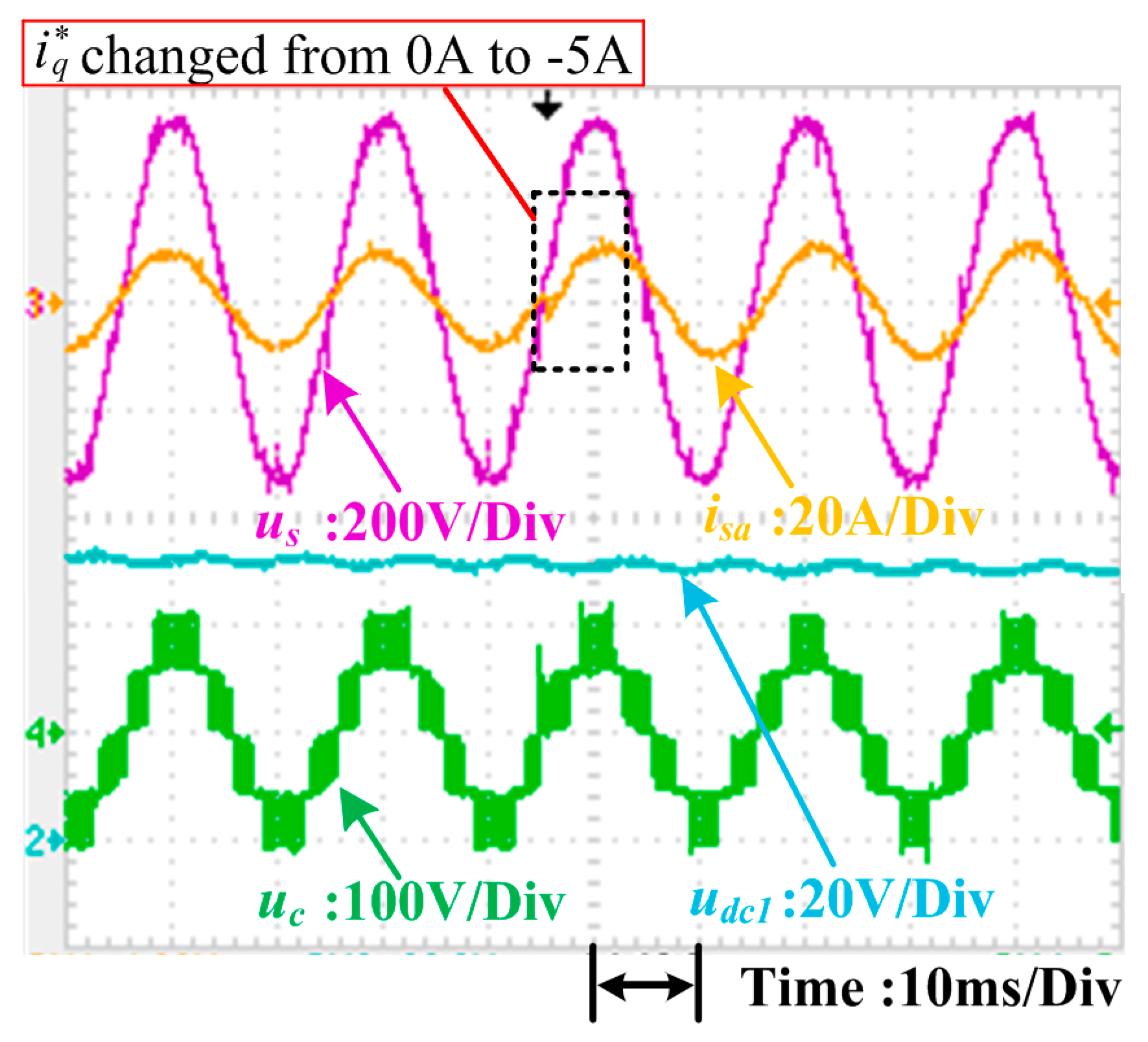
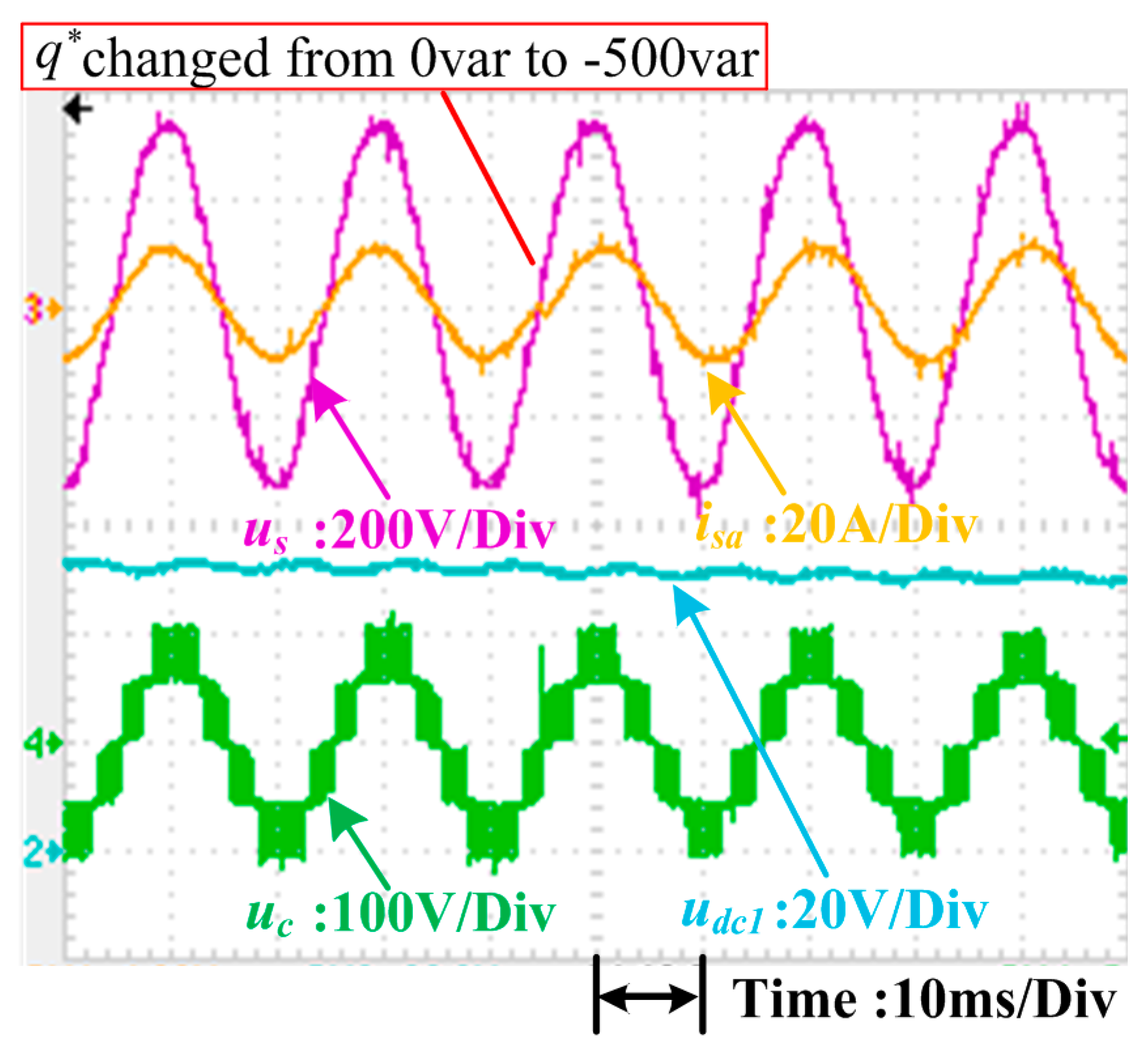
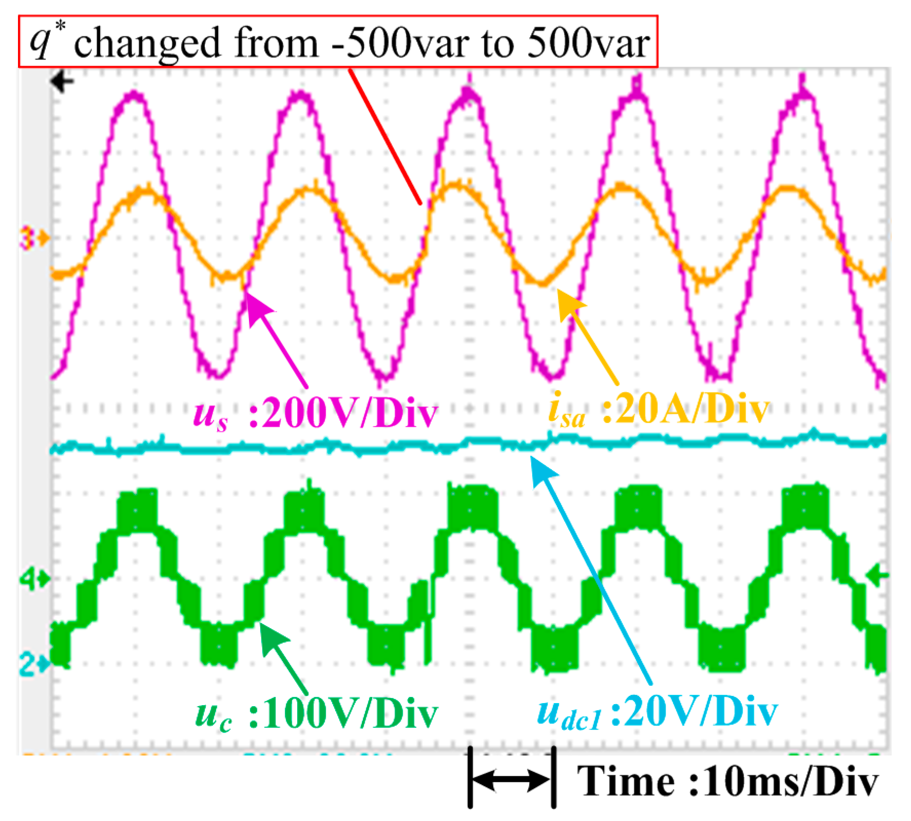
4.3. Dynamic Response Compared with dq Control

Currently, the most popular control method for the single-phase CHB converter is dq control. Several experiments were carried out to compare conventional dq control with the proposed control method. These experiments tested the dynamic responses of the systems under sudden power change conditions. In these tests, the total dc-link voltage udc_sum was kept at 100 V, and the system was connected to two resistive loads where R1 is 10 Ω and R2 is 15 Ω, respectively. The dynamic of the d-axis current i*d in the dq control was managed by the outer voltage loop, and active power p* in the proposed scheme was controlled by the outer power loop. Therefore, only step changes in the reactive current reference i*q in the dq control and reactive power reference q* in the proposed control were applied to evaluate the dynamic control performance of each. Differences in the dynamic performance of the dq control scheme and the proposed control method are illustrated in Figure 21, Figure 22, Figure 23, Figure 24, Figure 25, Figure 26, Figure 27 and Figure 28.
The total dc-link voltage udc_sum is 100 V; i*q and q* are given directly in each control method. Reactive power reference q* equals udc_sum * i*q (100 * i*q). For instance, when the step change of i*q is 5 A, the step change of q* equals 100 * i*q (500 var); when the step change of i*q is −5 A, the step change of q* equals 100 * i*q (−500 var).
As shown, the transient responses of the proposed power control method (less than 1 ms) were faster than the dq control method (more than 5 ms). In the dq control method, a time delay of 1/4 in the fundamental period arose from classical imaginary current construction.
Grid current and five-level staircase voltage continuous distortions also appeared in the dq control method due to conventional imaginary current construction.

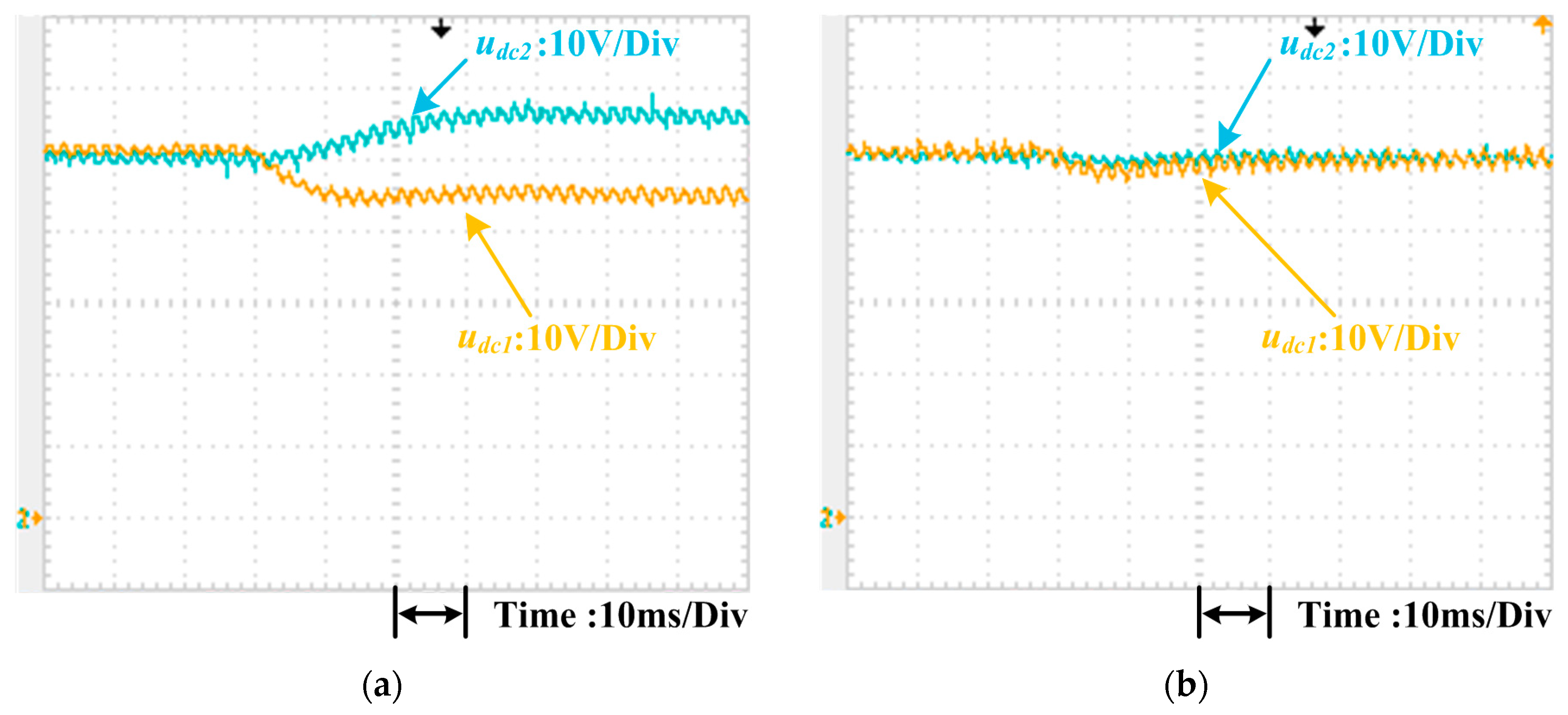
4.4. Voltage Balance Control

Besides grid current control, balance control of the dc-link voltages is another important issue. A dc-link voltage balance control method based on power was adopted to render the proposed power control strategy applicable to the CHB converter under unbalanced load conditions.
Unbalanced load experimental tests were conducted to verify the voltage-balancing performance of the presented scheme. In these experiments, the load resistor of the first H-bridge R1 was stepped from 15 Ω to 10 Ω whereas that of the second H-bridge R2 was maintained at 15 Ω. In Figure 29a, when the load resistors were changed, the dc-link voltage of the first H-bridge udc1 (10 V/division) declined from 50 V to 45 V, and that of the second H-bridge udc2 (10 V/division) increased from 50 V to 55 V. Figure 29b shows that when the voltage balance controller was adopted, the dc-link voltages could be controlled to 50 V when the load resistors were changed. Thus, the accuracy of the presented dc-link voltage balance control method was confirmed.

5. Discussion

The proposed power and voltage control method offers many advantages including no coordinate transformation, PLL, or conventional imaginary current construction. Moreover, it was found to exhibit faster transient responses and lower distortions compared with the conventional dq control method, as illustrated in Figure 21, Figure 22, Figure 23, Figure 24, Figure 25, Figure 26, Figure 27 and Figure 28.
The natural frame control scheme presented in [23] also shows the advantages of no coordinate transformation, PLL, or conventional imaginary current construction. Differ from the natural frame control scheme, the proposed scheme connects power control with current control through the instantaneous power theory. Besides, the proposed voltage balance control module is based on power, in which the power compensation values are used to eliminate the uneven power in active power p and reactive power q.
Even so, this control strategy has some limitations: First, although classical imaginary current construction is not necessary, the creation of an imaginary voltage component cannot be avoided. Therefore, an algorithm can be developed to reduce the time delay caused by imaginary voltage construction. Second, only the steady grid voltage condition was considered here, although abnormal operating states (e.g., grid voltage distortion) exist; thus, the control method should be optimized to make it applicable to such states.

6. Conclusions

A power control method is introduced for the single-phase CHB multilevel converter in this paper. A power-based dc-link voltage balance control module is also presented to eliminate the different dc-link voltages caused by the unbalanced loads.
The proposed power and voltage control method is designed in a virtual αβ stationary reference frame without coordinate transformation or phase-locked loop. So, the complicated calculation issue can be avoided. What is more, conventional imaginary current construction is not necessary. Problems like time delay can also be avoided. The inner loop current calculation is simplified compared with the conventional dq control scheme. Stability of the proposed control scheme can be guaranteed through the analysis based on small-signal model.
Simulation and experimental results were presented to verify the effectiveness of the proposed control method. In the steady state, the proposed method can obtain the sinusoidal grid current and unity power factor under unbalanced load conditions. Upon comparing the dynamic response of the presented control strategy with that of the dq control scheme, the conducted experiments indicate that the salient feature of the proposed scheme is as follows: the proposed scheme maintains a fast dynamic response advantage over the conventional dq control method. This approach has been shown to be useful for the single-phase CHB multilevel converter system. The proposed control scheme can also be utilized with other multilevel converter systems.

Author Contributions

The individual contribution of each co-author with regards to the reported research and writing of the paper is as follows. D.Y. conceived the idea, L.Y. carried out the experiments and analyzed the data, and all authors wrote the paper.

Acknowledgments

This study is partly supported by the National Nature Science Foundation of China (No. 61861003).

Conflicts of Interest

The authors declare no conflict of interest.

Nomenclature

CHBCascaded H-bridge
PWMPulse Width Modulation
DPCDirect Power Control
DCCDirect Current Control
P-DPCPredictive DPC
PLLPhase-Locked Loop
DSPDigital Signal Processor
MPCModel-Predictive Control
SOGISecond-Order Generalized Integrator
PIProportional-Integral
PRProportional-plus-Resonant
CPS-PWMCarrier, Phase-Shifted PWM
THDTotal Harmonic Distortion

References

  1. Noman, A.M.; Al-Shamma’a, A.A.; Addoweesh, K.E.; Alabduljabbar, A.A.; Alolah, A.I. Cascaded Multilevel Inverter Topology Based on Cascaded H-Bridge Multilevel Inverter. Energies 2018, 11, 895. [Google Scholar] [CrossRef]
  2. Aquila, A.D.; Liserre, M.; Monopoli, V.G.; Rotondo, P. Overview of PI-based solutions for the control of DC buses of a single-phase H-bridge multilevel active rectifier. IEEE Trans. Ind. Appl. 2008, 44, 857–866. [Google Scholar] [CrossRef]
  3. Yu, Y.; Konstantinou, G.; Townsend, C.D.; Agelidis, V.G. Comparison of zero-sequence injection methods in cascaded H-bridge multilevel converters for large-scale photovoltaic integration. IET Renew. Power Gener. 2017, 11, 603–613. [Google Scholar] [CrossRef]
  4. Wang, L.; Zhang, D.; Wang, Y.; Wu, B.; Athab, H.S. Power and voltage balance control of a novel three-phase solid-state transformer using multilevel cascaded H-bridge inverters for microgrid applications. IEEE Trans. Power Electron. 2016, 31, 3289–3310. [Google Scholar] [CrossRef]
  5. Yang, Z.; Sun, J.; Li, S.; Huang, M.; Zha, X.; Tang, Y. An adaptive carrier frequency optimization method for harmonic energy unbalance minimization in a cascaded H-bridge-based active power filter. IEEE Trans. Power Electron. 2018, 33, 1024–1037. [Google Scholar] [CrossRef]
  6. Song, W.; Ma, J.; Zhou, L.; Feng, X. Deadbeat predictive power control of single-phase three-level neutral-point-clamped converters using space-vector modulation for electric railway traction. IEEE Trans. Power Electron. 2016, 31, 721–732. [Google Scholar] [CrossRef]
  7. Ohnishi, T. Three PWM converter/inverter by means of instantaneous active and reactive power control. In Proceedings of the International Conference on Industrial Electronics, Control and Instrumentation. (IECON 1991), Kobe, Japan, 28 October–1 November 1991; pp. 819–824. [Google Scholar]
  8. Wang, X.; Sun, D. Three-vector-based low-complexity model predictive direct power control strategy for doubly fed induction generators. IEEE Trans. Power Electron. 2017, 32, 773–782. [Google Scholar] [CrossRef]
  9. Kim, I.; Chan, R.; Kwak, S. A voltage level based predictive direct power control for modular multilevel converter. IEEE Trans. Power Appl. 2017, 11, 784–792. [Google Scholar]
  10. Cheng, C.; Nian, H.; Wang, X.; Sun, D. Dead-beat predictive direct power control of voltage source inverters with optimised switching patterns. IET. Power Electron. 2017, 10, 1438–1451. [Google Scholar] [CrossRef]
  11. Ma, H.; Xie, Y.; Shi, Z. Improved direct power control for Vienna-type rectifiers based on sliding mode control. IET. Power Electron. 2016, 9, 427–434. [Google Scholar] [CrossRef]
  12. Ma, J.; Song, W.; Wang, S.; Feng, X. Model predictive direct power control for single phase three-level rectifier at low switching frequency. IEEE Trans. Power Electron. 2018, 33, 1050–1062. [Google Scholar] [CrossRef]
  13. Behrouzian, E.; Bongiorno, M. Investigation of negative-sequence injection capability of cascaded H-bridge converters in star and delta configuration. IEEE Trans. Power Electron. 2017, 32, 1675–1683. [Google Scholar] [CrossRef]
  14. Adam, G.P.; Abdelsalam, I.A.; Ahmed, K.H.; Williams, B.W. Hybrid multilevel converter with cascaded H-bridge cells for HVDC applications: Operating principle and scalability. IEEE Trans. Power Electron. 2015, 30, 65–77. [Google Scholar] [CrossRef]
  15. Wang, X.; He, Z.; Yang, J. Electric Vehicle Fast-Charging Station Unified Modeling and Stability Analysis in the dq Frame. Energies 2018, 11, 1195. [Google Scholar] [CrossRef]
  16. Liu, J.; Liu, Z. Harmonic Analyzing of the Double PWM Converter in DFIG Based on Mathematical Model. Energies 2017, 10, 2087. [Google Scholar] [CrossRef]
  17. Gu, Y.; Wang, Y.; Xiang, X.; Li, W.; He, X. Improved virtual vector control of single-phase inverter based on unified model. IEEE Trans. Energy Convers. 2014, 29, 611–618. [Google Scholar] [CrossRef]
  18. Zheng, X.; Xiao, L.; Wang, Z.; Lei, Y.; Wang, C. Control strategy without phase-locked loop based on coordinate transformation for three-phase AC/DC converter. IET. Power Electron. 2015, 8, 1701–1709. [Google Scholar] [CrossRef]
  19. Li, Y.; Yang, J.; Wang, H.; Ge, W.; Ma, Y. A Hybrid Filtering Technique-Based PLL Targeting Fast and Robust Tracking Performance under Distorted Grid Conditions. Energies 2018, 11, 973. [Google Scholar] [CrossRef]
  20. Hamed, H.A.; Abdou, A.F.; Bayoumi, E.; EL-Kholy, E.E. Effective design and implementation of GSS-PLL under voltage dip and phase interruption. IET. Power Electron. 2018, 11, 1018–1028. [Google Scholar] [CrossRef]
  21. Xiao, F.; Dong, L.; Li, L.; Liao, X. A frequency-fixed SOGI-based PLL for single-phase grid-connected converters. IEEE Trans. Power Electron. 2017, 21, 1713–1719. [Google Scholar] [CrossRef]
  22. Sahoo, S.; Prakash, S.; Mishra, S. Power quality improvement of grid-connected DC microgrids using repetitive learning-based PLL under abnormal grid conditions. IEEE Trans. Ind. Appl. 2018, 54, 82–90. [Google Scholar] [CrossRef]
  23. Yang, D.; Wu, N.; Yin, L.; Lu, Z. Natural frame control of single-phase cascaded H-bridge multilevel converter based on fictive-phases construction. IEEE Trans. Ind. Electron. 2018, 54, 3848–3857. [Google Scholar] [CrossRef]
  24. Chan, R.; Kwak, S. Improved Finite-Control-Set Model Predictive Control for Cascaded H-Bridge Inverters. Energies. 2018, 11, 355. [Google Scholar] [CrossRef]
  25. Zhang, Y.; Wu, X.; Yuan, X.; Wang, Y.; Dai, P. Fast model predictive control for multilevel cascaded H-bridge STATCOM with polynomial computation time. IEEE Trans. Ind. Electron. 2016, 63, 5231–5243. [Google Scholar] [CrossRef]
  26. Qi, C.; Chen, X.; Tu, P.; Wang, P. Deadbeat control for a single-phase cascaded H-bridge rectifier with voltage balancing modulation. IET Power Electron. 2018, 11, 610–617. [Google Scholar] [CrossRef]
  27. Song, W.; Deng, Z.; Wang, S.; Feng, X. A Simple Model Predictive Power Control Strategy for Single-Phase PWM Converters With Modulation Function Optimization. IEEE Trans. Power Electron. 2016, 31, 5279–5289. [Google Scholar] [CrossRef]
  28. Blahnik, V.; Kosan, T.; Peroutka, Z.; Talla, J. Control of a single-phase cascaded H-bridge active rectifier under unbalanced load. IEEE Trans. Power Electron. 2018, 33, 5519–5527. [Google Scholar] [CrossRef]
  29. Somkun, S.; Chunkag, V. Unified unbalanced synchronous reference frame current control for single-phase grid-connected voltage source converters. IEEE Trans. Ind. Electron. 2016, 63, 5425–5436. [Google Scholar] [CrossRef]
  30. Sha, D.; Xu, G.; Xu, Y. Utility direct interfaced charger/discharger employing unified voltage balance control for cascaded H-bridge units and decentralized control for CF-DAB modules. IEEE Trans. Ind. Electron. 2017, 64, 7831–7841. [Google Scholar] [CrossRef]
  31. Ebrahimi, M.; Khajehoddin, S.; Ghartemani, M.K. Fast and robust single-phase dq current controller for smart inverter applications. IEEE Trans. Power Electron. 2016, 31, 3968–3976. [Google Scholar] [CrossRef]
  32. Shi, J.; Gou, W.; Yuan, H.; Zhao, T.; Huang, A.Q. Research on voltage and power balance control for cascaded modular solid-state transformer. IEEE Trans. Power Electron. 2011, 26, 1154–1166. [Google Scholar] [CrossRef]
  33. Farivar, G.; Townsend, C.D.; Hredzak, B.; Pou, J.; Agelidis, V.G. Low-capacitance cascaded H-bridge multilevel STATCOM. IEEE Trans. Power Electron. 2016, 32, 1744–1754. [Google Scholar] [CrossRef]
  34. Qi, C.; Chen, X.; Tu, P.; Wang, P. Cell-by-cell-based finite-control- set model predictive control for a single-phase cascaded H-bridge rectifier. IEEE Trans. Power Electron. 2018, 33, 1654–1665. [Google Scholar] [CrossRef]
  35. Moeini, A.; Wang, S. A DC Link Sensor-Less Voltage Balancing Technique for Cascaded H-Bridge Multilevel Converters with Asymmetric Selective Harmonic Current Mitigation-PWM. IEEE Trans. Power Electron. 2018, 33, 7571–7581. [Google Scholar] [CrossRef]
  36. Farivar, G.; Hredzak, B.; Agelidis, V.G. Decoupled control system for cascaded H-bridge multilevel converter based STATCOM. IEEE Trans. Ind. Electron. 2016, 63, 322–331. [Google Scholar] [CrossRef]
  37. Zhao, T.; Wang, G.; Bhattacharya, S.; Huang, A.Q. Voltage and power balance control for a cascaded H-bridge converter-based solid-state transformer. IEEE Trans. Power Electron. 2013, 28, 1523–1532. [Google Scholar] [CrossRef]
  38. Chen, H.; Wu, P.; Lee, C.; Wang, C.; Yang, C.; Cheng, P. A flexible DC voltage balancing control based on the power flow management for star-connected cascaded H-bridge converter. IEEE Trans. Ind. Appl. 2016, 2, 4946–4954. [Google Scholar] [CrossRef]
  39. Moeini, A.; Wang, S. The state of charge balancing techniques for electrical vehicle charging stations with cascaded H-bridge multilevel converters. In Proceedings of the IEEE Applied Power Electronics Conference and Exposition—APEC, San Antonio, TX, USA, 4–8 March 2018; pp. 637–644. [Google Scholar]
  40. Yang, Y.; Zhou, K.; Wang, H.; Blaabjerg, F.; Wang, D.; Zhang, B. Frequency adaptive selective harmonic control for grid-connected inverters. IEEE Trans. Power Electron. 2015, 30, 3912–3924. [Google Scholar] [CrossRef]
Figure 1. Two-cell single-phase CHB converter.
Energies 11 02435 g001
Figure 2. Small-signal model of two-cell single-phase CHB converter in αβ frame coordination.
Energies 11 02435 g002
Figure 3. Schematic diagram of virtual αβ coordinate axis.
Energies 11 02435 g003
Figure 4. Conventional voltage balance controller [37].
Energies 11 02435 g004
Figure 5. Proposed voltage balance controller.
Energies 11 02435 g005
Figure 6. Proposed power and voltage control of CHB converter.
Energies 11 02435 g006
Figure 7. Power and voltage control module.
Energies 11 02435 g007
Figure 8. Basic double-loop controller structure diagram of the proposed power control.
Energies 11 02435 g008
Figure 9. Thevenin equivalent circuit of the basic double-loop.
Energies 11 02435 g009
Figure 10. Thevenin equivalent circuit with the voltage balance module controller.
Energies 11 02435 g010
Figure 11. Bode plot of the basic double-loop controller with the dc-link voltage balance module.
Energies 11 02435 g011
Figure 12. Simulation waveforms of CHB converter in steady state: (a) Grid voltage and grid current; (b) Five-level voltage staircase waveform.
Energies 11 02435 g012
Figure 13. q* changed from 0 var to 1500 var: (a) Dynamic response of the grid current; (b) Dynamic response of the reactive power.
Energies 11 02435 g013
Figure 14. q* changed from 0 var to −1500 var: (a) Dynamic response of the grid current; (b) Dynamic response of the reactive power.
Energies 11 02435 g014
Figure 15. Simulated response of dc-link voltages when load changed: (a) Without voltage balance control; (b) With voltage balance control.
Energies 11 02435 g015
Figure 16. Platform of the experiments.
Energies 11 02435 g016
Figure 17. Experimental waveforms of CHB converter in steady state.
Energies 11 02435 g017
Figure 18. THD of grid current in steady state.
Energies 11 02435 g018
Figure 19. Experimental grid currents of CHB capacitive mode.
Energies 11 02435 g019
Figure 20. Experimental grid currents of CHB inductive mode.
Energies 11 02435 g020
Figure 21. i*q changed from 0 A to 5 A (dq control method).
Energies 11 02435 g021
Figure 22. q* changed from 0 var to 500 var (proposed control method).
Energies 11 02435 g022
Figure 23. i*q changed from 0 A to −5 A (dq control method).
Energies 11 02435 g023
Figure 24. q* changed from 0 var to −500 var (proposed control method).
Energies 11 02435 g024
Figure 25. i*q changed from 5 A to −5 A (dq control method).
Energies 11 02435 g025
Figure 26. q* changed from 500 var to −500 var (proposed control method).
Energies 11 02435 g026
Figure 27. i*q changed from −5 A to 5 A (dq control method).
Energies 11 02435 g027
Figure 28. q* changed from −500 var to 500 var (proposed control method).
Energies 11 02435 g028
Figure 29. Experimental response of dc-link voltages when load changed: (a) Without voltage balance controller, (b) With voltage balance controller.
Energies 11 02435 g029
Table 1. Parameters Used For Simulation.
ParameterSymbolSimulation Value
Grid voltage rms valueus220 V
Grid frequencyfg50 Hz
Input inductanceL3.0 mH
dc-link total voltageUdc400 V
dc-link capacitanceC1, C24700 μF
dc-link load resistanceR1, R210 Ω, 15 Ω
Switching frequencyfsw10 kHz
Inner current loop control parametersP, R, wc0.5, 100, 6.28
Outer power loop control parametersP, I0.1, 8

